JP6636719B2 - 電線接続用端子および電線接続用端子と電線の接合方法 - Google Patents
電線接続用端子および電線接続用端子と電線の接合方法 Download PDFInfo
- Publication number
- JP6636719B2 JP6636719B2 JP2015099051A JP2015099051A JP6636719B2 JP 6636719 B2 JP6636719 B2 JP 6636719B2 JP 2015099051 A JP2015099051 A JP 2015099051A JP 2015099051 A JP2015099051 A JP 2015099051A JP 6636719 B2 JP6636719 B2 JP 6636719B2
- Authority
- JP
- Japan
- Prior art keywords
- electric wire
- connection terminal
- wire connection
- caulking
- caulking piece
- Prior art date
- Legal status (The legal status is an assumption and is not a legal conclusion. Google has not performed a legal analysis and makes no representation as to the accuracy of the status listed.)
- Expired - Fee Related
Links
Images


Classifications
-
- H—ELECTRICITY
- H01—ELECTRIC ELEMENTS
- H01R—ELECTRICALLY-CONDUCTIVE CONNECTIONS; STRUCTURAL ASSOCIATIONS OF A PLURALITY OF MUTUALLY-INSULATED ELECTRICAL CONNECTING ELEMENTS; COUPLING DEVICES; CURRENT COLLECTORS
- H01R4/00—Electrically-conductive connections between two or more conductive members in direct contact, i.e. touching one another; Means for effecting or maintaining such contact; Electrically-conductive connections having two or more spaced connecting locations for conductors and using contact members penetrating insulation
- H01R4/02—Soldered or welded connections
- H01R4/023—Soldered or welded connections between cables or wires and terminals
-
- H—ELECTRICITY
- H01—ELECTRIC ELEMENTS
- H01R—ELECTRICALLY-CONDUCTIVE CONNECTIONS; STRUCTURAL ASSOCIATIONS OF A PLURALITY OF MUTUALLY-INSULATED ELECTRICAL CONNECTING ELEMENTS; COUPLING DEVICES; CURRENT COLLECTORS
- H01R4/00—Electrically-conductive connections between two or more conductive members in direct contact, i.e. touching one another; Means for effecting or maintaining such contact; Electrically-conductive connections having two or more spaced connecting locations for conductors and using contact members penetrating insulation
- H01R4/02—Soldered or welded connections
-
- H—ELECTRICITY
- H01—ELECTRIC ELEMENTS
- H01R—ELECTRICALLY-CONDUCTIVE CONNECTIONS; STRUCTURAL ASSOCIATIONS OF A PLURALITY OF MUTUALLY-INSULATED ELECTRICAL CONNECTING ELEMENTS; COUPLING DEVICES; CURRENT COLLECTORS
- H01R11/00—Individual connecting elements providing two or more spaced connecting locations for conductive members which are, or may be, thereby interconnected, e.g. end pieces for wires or cables supported by the wire or cable and having means for facilitating electrical connection to some other wire, terminal, or conductive member, blocks of binding posts
- H01R11/11—End pieces or tapping pieces for wires, supported by the wire and for facilitating electrical connection to some other wire, terminal or conductive member
- H01R11/12—End pieces terminating in an eye, hook, or fork
-
- H—ELECTRICITY
- H01—ELECTRIC ELEMENTS
- H01R—ELECTRICALLY-CONDUCTIVE CONNECTIONS; STRUCTURAL ASSOCIATIONS OF A PLURALITY OF MUTUALLY-INSULATED ELECTRICAL CONNECTING ELEMENTS; COUPLING DEVICES; CURRENT COLLECTORS
- H01R13/00—Details of coupling devices of the kinds covered by groups H01R12/70 or H01R24/00 - H01R33/00
- H01R13/02—Contact members
- H01R13/03—Contact members characterised by the material, e.g. plating, or coating materials
-
- H—ELECTRICITY
- H01—ELECTRIC ELEMENTS
- H01R—ELECTRICALLY-CONDUCTIVE CONNECTIONS; STRUCTURAL ASSOCIATIONS OF A PLURALITY OF MUTUALLY-INSULATED ELECTRICAL CONNECTING ELEMENTS; COUPLING DEVICES; CURRENT COLLECTORS
- H01R4/00—Electrically-conductive connections between two or more conductive members in direct contact, i.e. touching one another; Means for effecting or maintaining such contact; Electrically-conductive connections having two or more spaced connecting locations for conductors and using contact members penetrating insulation
- H01R4/10—Electrically-conductive connections between two or more conductive members in direct contact, i.e. touching one another; Means for effecting or maintaining such contact; Electrically-conductive connections having two or more spaced connecting locations for conductors and using contact members penetrating insulation effected solely by twisting, wrapping, bending, crimping, or other permanent deformation
- H01R4/18—Electrically-conductive connections between two or more conductive members in direct contact, i.e. touching one another; Means for effecting or maintaining such contact; Electrically-conductive connections having two or more spaced connecting locations for conductors and using contact members penetrating insulation effected solely by twisting, wrapping, bending, crimping, or other permanent deformation by crimping
-
- H—ELECTRICITY
- H01—ELECTRIC ELEMENTS
- H01R—ELECTRICALLY-CONDUCTIVE CONNECTIONS; STRUCTURAL ASSOCIATIONS OF A PLURALITY OF MUTUALLY-INSULATED ELECTRICAL CONNECTING ELEMENTS; COUPLING DEVICES; CURRENT COLLECTORS
- H01R4/00—Electrically-conductive connections between two or more conductive members in direct contact, i.e. touching one another; Means for effecting or maintaining such contact; Electrically-conductive connections having two or more spaced connecting locations for conductors and using contact members penetrating insulation
- H01R4/10—Electrically-conductive connections between two or more conductive members in direct contact, i.e. touching one another; Means for effecting or maintaining such contact; Electrically-conductive connections having two or more spaced connecting locations for conductors and using contact members penetrating insulation effected solely by twisting, wrapping, bending, crimping, or other permanent deformation
- H01R4/18—Electrically-conductive connections between two or more conductive members in direct contact, i.e. touching one another; Means for effecting or maintaining such contact; Electrically-conductive connections having two or more spaced connecting locations for conductors and using contact members penetrating insulation effected solely by twisting, wrapping, bending, crimping, or other permanent deformation by crimping
- H01R4/183—Electrically-conductive connections between two or more conductive members in direct contact, i.e. touching one another; Means for effecting or maintaining such contact; Electrically-conductive connections having two or more spaced connecting locations for conductors and using contact members penetrating insulation effected solely by twisting, wrapping, bending, crimping, or other permanent deformation by crimping for cylindrical elongated bodies, e.g. cables having circular cross-section
- H01R4/184—Electrically-conductive connections between two or more conductive members in direct contact, i.e. touching one another; Means for effecting or maintaining such contact; Electrically-conductive connections having two or more spaced connecting locations for conductors and using contact members penetrating insulation effected solely by twisting, wrapping, bending, crimping, or other permanent deformation by crimping for cylindrical elongated bodies, e.g. cables having circular cross-section comprising a U-shaped wire-receiving portion
-
- H—ELECTRICITY
- H01—ELECTRIC ELEMENTS
- H01R—ELECTRICALLY-CONDUCTIVE CONNECTIONS; STRUCTURAL ASSOCIATIONS OF A PLURALITY OF MUTUALLY-INSULATED ELECTRICAL CONNECTING ELEMENTS; COUPLING DEVICES; CURRENT COLLECTORS
- H01R4/00—Electrically-conductive connections between two or more conductive members in direct contact, i.e. touching one another; Means for effecting or maintaining such contact; Electrically-conductive connections having two or more spaced connecting locations for conductors and using contact members penetrating insulation
- H01R4/10—Electrically-conductive connections between two or more conductive members in direct contact, i.e. touching one another; Means for effecting or maintaining such contact; Electrically-conductive connections having two or more spaced connecting locations for conductors and using contact members penetrating insulation effected solely by twisting, wrapping, bending, crimping, or other permanent deformation
- H01R4/18—Electrically-conductive connections between two or more conductive members in direct contact, i.e. touching one another; Means for effecting or maintaining such contact; Electrically-conductive connections having two or more spaced connecting locations for conductors and using contact members penetrating insulation effected solely by twisting, wrapping, bending, crimping, or other permanent deformation by crimping
- H01R4/187—Electrically-conductive connections between two or more conductive members in direct contact, i.e. touching one another; Means for effecting or maintaining such contact; Electrically-conductive connections having two or more spaced connecting locations for conductors and using contact members penetrating insulation effected solely by twisting, wrapping, bending, crimping, or other permanent deformation by crimping combined with soldering or welding
-
- H—ELECTRICITY
- H01—ELECTRIC ELEMENTS
- H01R—ELECTRICALLY-CONDUCTIVE CONNECTIONS; STRUCTURAL ASSOCIATIONS OF A PLURALITY OF MUTUALLY-INSULATED ELECTRICAL CONNECTING ELEMENTS; COUPLING DEVICES; CURRENT COLLECTORS
- H01R4/00—Electrically-conductive connections between two or more conductive members in direct contact, i.e. touching one another; Means for effecting or maintaining such contact; Electrically-conductive connections having two or more spaced connecting locations for conductors and using contact members penetrating insulation
- H01R4/58—Electrically-conductive connections between two or more conductive members in direct contact, i.e. touching one another; Means for effecting or maintaining such contact; Electrically-conductive connections having two or more spaced connecting locations for conductors and using contact members penetrating insulation characterised by the form or material of the contacting members
- H01R4/62—Connections between conductors of different materials; Connections between or with aluminium or steel-core aluminium conductors
- H01R4/625—Soldered or welded connections
-
- H—ELECTRICITY
- H01—ELECTRIC ELEMENTS
- H01R—ELECTRICALLY-CONDUCTIVE CONNECTIONS; STRUCTURAL ASSOCIATIONS OF A PLURALITY OF MUTUALLY-INSULATED ELECTRICAL CONNECTING ELEMENTS; COUPLING DEVICES; CURRENT COLLECTORS
- H01R43/00—Apparatus or processes specially adapted for manufacturing, assembling, maintaining, or repairing of line connectors or current collectors or for joining electric conductors
- H01R43/02—Apparatus or processes specially adapted for manufacturing, assembling, maintaining, or repairing of line connectors or current collectors or for joining electric conductors for soldered or welded connections
-
- H—ELECTRICITY
- H01—ELECTRIC ELEMENTS
- H01R—ELECTRICALLY-CONDUCTIVE CONNECTIONS; STRUCTURAL ASSOCIATIONS OF A PLURALITY OF MUTUALLY-INSULATED ELECTRICAL CONNECTING ELEMENTS; COUPLING DEVICES; CURRENT COLLECTORS
- H01R43/00—Apparatus or processes specially adapted for manufacturing, assembling, maintaining, or repairing of line connectors or current collectors or for joining electric conductors
- H01R43/02—Apparatus or processes specially adapted for manufacturing, assembling, maintaining, or repairing of line connectors or current collectors or for joining electric conductors for soldered or welded connections
- H01R43/0263—Apparatus or processes specially adapted for manufacturing, assembling, maintaining, or repairing of line connectors or current collectors or for joining electric conductors for soldered or welded connections for positioning or holding parts during soldering or welding process
-
- H—ELECTRICITY
- H01—ELECTRIC ELEMENTS
- H01R—ELECTRICALLY-CONDUCTIVE CONNECTIONS; STRUCTURAL ASSOCIATIONS OF A PLURALITY OF MUTUALLY-INSULATED ELECTRICAL CONNECTING ELEMENTS; COUPLING DEVICES; CURRENT COLLECTORS
- H01R43/00—Apparatus or processes specially adapted for manufacturing, assembling, maintaining, or repairing of line connectors or current collectors or for joining electric conductors
- H01R43/04—Apparatus or processes specially adapted for manufacturing, assembling, maintaining, or repairing of line connectors or current collectors or for joining electric conductors for forming connections by deformation, e.g. crimping tool
- H01R43/048—Crimping apparatus or processes
-
- H—ELECTRICITY
- H01—ELECTRIC ELEMENTS
- H01R—ELECTRICALLY-CONDUCTIVE CONNECTIONS; STRUCTURAL ASSOCIATIONS OF A PLURALITY OF MUTUALLY-INSULATED ELECTRICAL CONNECTING ELEMENTS; COUPLING DEVICES; CURRENT COLLECTORS
- H01R4/00—Electrically-conductive connections between two or more conductive members in direct contact, i.e. touching one another; Means for effecting or maintaining such contact; Electrically-conductive connections having two or more spaced connecting locations for conductors and using contact members penetrating insulation
- H01R4/58—Electrically-conductive connections between two or more conductive members in direct contact, i.e. touching one another; Means for effecting or maintaining such contact; Electrically-conductive connections having two or more spaced connecting locations for conductors and using contact members penetrating insulation characterised by the form or material of the contacting members
- H01R4/62—Connections between conductors of different materials; Connections between or with aluminium or steel-core aluminium conductors
Landscapes
- Engineering & Computer Science (AREA)
- Manufacturing & Machinery (AREA)
- Connections Effected By Soldering, Adhesion, Or Permanent Deformation (AREA)
- Manufacturing Of Electrical Connectors (AREA)
Description
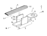
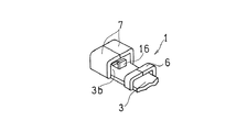
2:コネクタ部
3:電線接続部
3a:延出部分
3b:接続面
4:段差部
5:電線
6:かしめ部
61:第1のかしめ部
62:第2のかしめ部
8:第1のかしめ部の電線収納部
9:第2のかしめ部の電線収納部
10:上電極(第1の加熱電極)
11:上電極(第2の加熱電極)
12:下電極(第1の加熱電極または第2の加熱電極)
15:貫通部位
16:突出部
Claims (9)
- 電線を外部の導体に電気的に接続させる電線接続用端子であって、
前記導体に取り付けられるコネクタ部と、複数の芯線を束ねた電線が接続面に半田付けにより接続される電線接続部とを備え、
前記電線接続部は、かしめられて前記電線を保持するかしめ部を有し、さらに、
前記コネクタ部と前記かしめ部との間に、前記接続面から突出する段差部を備え、
前記電線の端部に付着している半田が前記段差部に固着している、電線接続用端子。 - 請求項1に記載の電線接続用端子であって、
さらに、
前記電線接続部は、前記かしめ部に対して前記段差部とは逆方向に延出された延出部分を備えた、電線接続用端子。 - 請求項1または2に記載の電線接続用端子であって、
前記電線がアルミニウムまたはアルミニウム合金製であり、
前記電線接続用端子が前記電線とは異なる材質である銅または銅合金製からなり、少なくとも前記接続面に電蝕回避の錫めっき処理がなされている、電線接続用端子。 - 請求項1から3のいずれか一項に記載の電線接続用端子であって、
前記かしめ部は、かしめられて前記電線を第1の外力が加わった応力下で保持する第1のかしめ片と、かしめられて前記電線を外力が加わらない無応力下で覆う第2のかしめ片とを備えて、両かしめ片が前記電線接続部の長手方向に沿って所定間隔に離間して配置されており、
前記第1のかしめ片による前記第1の外力が加わった応力下で、前記電線接続用端子と前記電線とが電気的に接合されているとともに、
前記第2のかしめ片による前記無応力下で、前記電線接続用端子と前記電線との半田付けによって、前記電線接続用端子と前記電線が機械的に接合されている、電線接続用端子。 - 請求項4に記載の電線接続用端子であって、
かしめられた前記第1および第2のかしめ片はそれぞれ電線が挿入される電線収納部を有し、前記第1のかしめ片の前記電線収納部の横断面積は、前記電線収納部外の電線の横断面積よりも小さく形成されており、前記第2のかしめ片の前記電線収納部の横断面積は、前記電線収納部外の電線の横断面積よりも大きく形成されている、電線接続用端子。 - 請求項4または5に記載の電線接続用端子であって、
前記第2のかしめ片が、前記電線と直交する方向に貫通する1つ以上の貫通部位を有する、電線接続用端子。 - 請求項4から6のいずれか一項に記載の電線接続用端子であって、
前記電線接続部は、前記接続面から突出する突出部を有する、電線接続用端子。 - 請求項4に記載の電線接続用端子に、電線を接合する方法であって、
前記第1のかしめ片をかしめることにより、前記電線を前記第1のかしめ片による前記第1の外力が加わった応力下で、前記電線接続用端子と前記電線とを電気的に接合する電気的接合工程と、
前記第2のかしめ片を電線に外力が加わらないようにかしめることで、前記第2のかしめ片を前記電線に近接させ、前記第2のかしめ片を加熱する第1の加熱電極へ通電し、前記電線を無応力下で加熱した状態で、前記第2のかしめ片と前記電線との間隙から電線にフラックスおよび半田を投入して前記電線接続用端子に前記電線を半田付けすることによって、前記電線接続用端子と前記電線を機械的に接合する機械的接合工程とを含む、電線接続用端子と電線の接合方法。 - 請求項8に記載の電線接続用端子と電線の接合方法であって、
前記機械的接合工程において、
前記第1のかしめ片と前記第2のかしめ片との間に位置する前記電線を、第2の加熱電極により第2の外力を加えながら加熱した状態とし、前記間隙に投入されて両かしめ片間の電線に流入した前記フラックスおよび前記半田によって、両かしめ片間の電線における前記芯線同士を半田付けする、電線接続用端子と電線の接合方法。
Priority Applications (6)
| Application Number | Priority Date | Filing Date | Title |
|---|---|---|---|
| JP2015099051A JP6636719B2 (ja) | 2015-05-14 | 2015-05-14 | 電線接続用端子および電線接続用端子と電線の接合方法 |
| PCT/JP2016/064512 WO2016182084A1 (ja) | 2015-05-14 | 2016-05-16 | 電線接続用端子および電線接続用端子と電線の接合方法 |
| US15/573,636 US10777911B2 (en) | 2015-05-14 | 2016-05-16 | Electric cable connecting terminal and method for connecting together electric cable connecting terminal and electric cable |
| DE112016002171.2T DE112016002171T5 (de) | 2015-05-14 | 2016-05-16 | Anschluss zur leitungsverbindung und verfahren zur verbindung des anschlusses mit der leitung |
| KR1020177033054A KR102586402B1 (ko) | 2015-05-14 | 2016-05-16 | 전선접속용 단자 및 전선접속용 단자와 전선의 접합방법 |
| CN201680026695.8A CN107615590B (zh) | 2015-05-14 | 2016-05-16 | 接线端子以及接线端子与电线的接合方法 |
Applications Claiming Priority (1)
| Application Number | Priority Date | Filing Date | Title |
|---|---|---|---|
| JP2015099051A JP6636719B2 (ja) | 2015-05-14 | 2015-05-14 | 電線接続用端子および電線接続用端子と電線の接合方法 |
Publications (2)
| Publication Number | Publication Date |
|---|---|
| JP2016219108A JP2016219108A (ja) | 2016-12-22 |
| JP6636719B2 true JP6636719B2 (ja) | 2020-01-29 |
Family
ID=57249093
Family Applications (1)
| Application Number | Title | Priority Date | Filing Date |
|---|---|---|---|
| JP2015099051A Expired - Fee Related JP6636719B2 (ja) | 2015-05-14 | 2015-05-14 | 電線接続用端子および電線接続用端子と電線の接合方法 |
Country Status (6)
| Country | Link |
|---|---|
| US (1) | US10777911B2 (ja) |
| JP (1) | JP6636719B2 (ja) |
| KR (1) | KR102586402B1 (ja) |
| CN (1) | CN107615590B (ja) |
| DE (1) | DE112016002171T5 (ja) |
| WO (1) | WO2016182084A1 (ja) |
Families Citing this family (6)
| Publication number | Priority date | Publication date | Assignee | Title |
|---|---|---|---|---|
| JP2019003869A (ja) * | 2017-06-16 | 2019-01-10 | 田淵電機株式会社 | 電線束と端子との接続構造及び接続方法 |
| CN110336171A (zh) * | 2019-06-13 | 2019-10-15 | 淮阴工学院 | 多类o型端子的转换套取装置 |
| US11264735B1 (en) * | 2020-08-28 | 2022-03-01 | TE Connectivity Services Gmbh | Electrical terminal for terminating a wide size range of magnet wires |
| CN112103744B (zh) * | 2020-09-08 | 2021-12-31 | 湖南湘联电缆有限公司 | 一种用于电缆生产的对接装置 |
| CN113017334A (zh) * | 2021-05-11 | 2021-06-25 | 青岛庆友石墨烯科技有限公司 | 石墨烯水暖床垫生产工艺 |
| KR102852199B1 (ko) * | 2023-12-27 | 2025-08-29 | 주식회사 유에이치비 | 와이어링 하네스 터미널 |
Family Cites Families (18)
| Publication number | Priority date | Publication date | Assignee | Title |
|---|---|---|---|---|
| US3777302A (en) * | 1971-11-26 | 1973-12-04 | Amp Inc | Electrical contact terminal having closed entry receptacle and connector |
| JPH0443857U (ja) * | 1990-08-14 | 1992-04-14 | ||
| JPH08241744A (ja) * | 1995-03-02 | 1996-09-17 | Sumitomo Wiring Syst Ltd | 端子金具 |
| JP3214393B2 (ja) * | 1997-04-16 | 2001-10-02 | 住友電装株式会社 | アース用端子金具 |
| JP2002298962A (ja) * | 2001-03-30 | 2002-10-11 | Jst Mfg Co Ltd | 樹脂ハンダを用いた電気接触子、電気コネクタ及びこれらのプリント配線板への接続方法 |
| DE10147908B4 (de) * | 2001-09-28 | 2004-01-29 | Gilliam, J., Dipl.-Ing. | Elektrischer Anschluss |
| JP2006286385A (ja) | 2005-03-31 | 2006-10-19 | Asahi Electric Works Ltd | 端子金具と撚り線との圧着接続構造 |
| JP5190306B2 (ja) * | 2008-06-24 | 2013-04-24 | 田淵電機株式会社 | 端子と電線の接合方法およびこれに用いられる電極 |
| EP2151892B1 (en) * | 2008-08-07 | 2017-05-03 | Sumitomo Wiring Systems, Ltd. | A terminal fitting and connecting method therefor |
| US9385449B2 (en) * | 2009-02-16 | 2016-07-05 | Carlisle Interconnect Technologies, Inc. | Terminal/connector having integral oxide breaker element |
| JP4841009B2 (ja) * | 2009-04-06 | 2011-12-21 | 株式会社タムラ製作所 | アルミ電線接続端子 |
| CN101659935B (zh) | 2009-09-01 | 2011-06-15 | 佛山市正典生物技术有限公司 | 可调式超静增氧机在球虫卵囊孢子化发育中的应用 |
| JP5393422B2 (ja) * | 2009-12-09 | 2014-01-22 | 矢崎総業株式会社 | 塗布剤の硬化方法 |
| DE102010038465A1 (de) * | 2010-07-27 | 2012-02-02 | Robert Bosch Gmbh | Elektrische Verbindung |
| JP5622314B2 (ja) * | 2010-10-12 | 2014-11-12 | 矢崎総業株式会社 | コネクタ端子の電線接続構造 |
| KR101254311B1 (ko) * | 2011-11-28 | 2013-04-12 | 한국단자공업 주식회사 | 터미널 |
| JP6074285B2 (ja) * | 2013-02-15 | 2017-02-01 | 田淵電機株式会社 | 端子と電線の接合方法および電線接続用の端子 |
| JP5369249B1 (ja) * | 2013-08-06 | 2013-12-18 | 日新製鋼株式会社 | 圧着端子および圧着端子付き電線 |
-
2015
- 2015-05-14 JP JP2015099051A patent/JP6636719B2/ja not_active Expired - Fee Related
-
2016
- 2016-05-16 WO PCT/JP2016/064512 patent/WO2016182084A1/ja not_active Ceased
- 2016-05-16 US US15/573,636 patent/US10777911B2/en not_active Expired - Fee Related
- 2016-05-16 KR KR1020177033054A patent/KR102586402B1/ko active Active
- 2016-05-16 DE DE112016002171.2T patent/DE112016002171T5/de not_active Withdrawn
- 2016-05-16 CN CN201680026695.8A patent/CN107615590B/zh not_active Expired - Fee Related
Also Published As
| Publication number | Publication date |
|---|---|
| KR102586402B1 (ko) | 2023-10-06 |
| US10777911B2 (en) | 2020-09-15 |
| WO2016182084A1 (ja) | 2016-11-17 |
| KR20180006619A (ko) | 2018-01-18 |
| CN107615590A (zh) | 2018-01-19 |
| JP2016219108A (ja) | 2016-12-22 |
| CN107615590B (zh) | 2020-07-24 |
| US20180151962A1 (en) | 2018-05-31 |
| DE112016002171T5 (de) | 2018-02-15 |
Similar Documents
| Publication | Publication Date | Title |
|---|---|---|
| KR102586402B1 (ko) | 전선접속용 단자 및 전선접속용 단자와 전선의 접합방법 | |
| WO2016017013A1 (ja) | 端子と電線の接合方法および電線接続用の端子 | |
| WO2012011394A1 (ja) | 電線付き端子金具およびその製造方法 | |
| JP2007531208A (ja) | アルミニウムから成る導電体に端子エレメントを結合する方法、及びこの方法によって製造される導電体 | |
| JP5369637B2 (ja) | 端子金具付き電線及びその製造方法 | |
| WO2011118416A1 (ja) | 端子金具付き電線及びその製造方法 | |
| JP5219913B2 (ja) | ターミナル、モータ及び電気機器 | |
| JP5460808B2 (ja) | ターミナル、モータ及び電気機器 | |
| JP5237143B2 (ja) | 電線接続用の端子、電線接続構造および電線と端子の接続方法 | |
| JP6074285B2 (ja) | 端子と電線の接合方法および電線接続用の端子 | |
| JP5116734B2 (ja) | ターミナル、モータ及び電気機器 | |
| CN108879131A (zh) | 带端子的电线 | |
| JP2017183184A (ja) | 端子部付き電線及びその製造方法 | |
| JP3019285B2 (ja) | 圧着端子、及び圧着端子と電線の接続方法 | |
| JP2017091800A (ja) | 導電部材 | |
| CN105309042B (zh) | 感应加热体及感应加热烹调器 | |
| US20160134027A1 (en) | Terminal bonding structure for wire and electrode for resistance-welding | |
| JP2019003869A (ja) | 電線束と端子との接続構造及び接続方法 | |
| JPH0982447A (ja) | 電線接続方法 | |
| JP2016046070A (ja) | 端子金具付き電線 | |
| JP5558292B2 (ja) | 導電接合端子の製造方法 | |
| JP2016051663A (ja) | 端子付電線及び端子付電線の製造方法 | |
| JP2017152094A (ja) | 端子部材 | |
| JP2013152805A (ja) | 端子付き電線およびその製造方法 | |
| KR200466961Y1 (ko) | 터미널 |
Legal Events
| Date | Code | Title | Description |
|---|---|---|---|
| A621 | Written request for application examination |
Free format text: JAPANESE INTERMEDIATE CODE: A621 Effective date: 20180509 |
|
| A131 | Notification of reasons for refusal |
Free format text: JAPANESE INTERMEDIATE CODE: A131 Effective date: 20190514 |
|
| A521 | Request for written amendment filed |
Free format text: JAPANESE INTERMEDIATE CODE: A523 Effective date: 20190712 |
|
| A131 | Notification of reasons for refusal |
Free format text: JAPANESE INTERMEDIATE CODE: A131 Effective date: 20190903 |
|
| A521 | Request for written amendment filed |
Free format text: JAPANESE INTERMEDIATE CODE: A523 Effective date: 20191101 |
|
| TRDD | Decision of grant or rejection written | ||
| A01 | Written decision to grant a patent or to grant a registration (utility model) |
Free format text: JAPANESE INTERMEDIATE CODE: A01 Effective date: 20191203 |
|
| A61 | First payment of annual fees (during grant procedure) |
Free format text: JAPANESE INTERMEDIATE CODE: A61 Effective date: 20191219 |
|
| R150 | Certificate of patent or registration of utility model |
Ref document number: 6636719 Country of ref document: JP Free format text: JAPANESE INTERMEDIATE CODE: R150 |
|
| R250 | Receipt of annual fees |
Free format text: JAPANESE INTERMEDIATE CODE: R250 |
|
| S533 | Written request for registration of change of name |
Free format text: JAPANESE INTERMEDIATE CODE: R313533 |
|
| R360 | Written notification for declining of transfer of rights |
Free format text: JAPANESE INTERMEDIATE CODE: R360 |
|
| R360 | Written notification for declining of transfer of rights |
Free format text: JAPANESE INTERMEDIATE CODE: R360 |
|
| R371 | Transfer withdrawn |
Free format text: JAPANESE INTERMEDIATE CODE: R371 |
|
| S533 | Written request for registration of change of name |
Free format text: JAPANESE INTERMEDIATE CODE: R313533 |
|
| R350 | Written notification of registration of transfer |
Free format text: JAPANESE INTERMEDIATE CODE: R350 |
|
| R250 | Receipt of annual fees |
Free format text: JAPANESE INTERMEDIATE CODE: R250 |
|
| LAPS | Cancellation because of no payment of annual fees |