JP6643143B2 - Main rope rod rotation prevention jig - Google Patents

Main rope rod rotation prevention jig Download PDF

Info

Publication number
JP6643143B2
JP6643143B2 JP2016036591A JP2016036591A JP6643143B2 JP 6643143 B2 JP6643143 B2 JP 6643143B2 JP 2016036591 A JP2016036591 A JP 2016036591A JP 2016036591 A JP2016036591 A JP 2016036591A JP 6643143 B2 JP6643143 B2 JP 6643143B2
Authority
JP
Japan
Prior art keywords
rod member
main rope
jig
weight
side rod
Prior art date
Legal status (The legal status is an assumption and is not a legal conclusion. Google has not performed a legal analysis and makes no representation as to the accuracy of the status listed.)
Active
Application number
JP2016036591A
Other languages
Japanese (ja)
Other versions
JP2017154825A (en
Inventor
政秀 硯川
政秀 硯川
孝祐 東島
孝祐 東島
Current Assignee (The listed assignees may be inaccurate. Google has not performed a legal analysis and makes no representation or warranty as to the accuracy of the list.)
Mitsubishi Electric Building Solutions Corp
Original Assignee
Mitsubishi Electric Building Techno Service Co Ltd
Priority date (The priority date is an assumption and is not a legal conclusion. Google has not performed a legal analysis and makes no representation as to the accuracy of the date listed.)
Filing date
Publication date
Application filed by Mitsubishi Electric Building Techno Service Co Ltd filed Critical Mitsubishi Electric Building Techno Service Co Ltd
Priority to JP2016036591A priority Critical patent/JP6643143B2/en
Publication of JP2017154825A publication Critical patent/JP2017154825A/en
Application granted granted Critical
Publication of JP6643143B2 publication Critical patent/JP6643143B2/en
Active legal-status Critical Current
Anticipated expiration legal-status Critical

Links

Images

Landscapes

  • Maintenance And Inspection Apparatuses For Elevators (AREA)
  • Lift-Guide Devices, And Elevator Ropes And Cables (AREA)

Description

本発明は、エレベータの複数の主ロープとカウンタウェイトとの接続部における主ロープの張力調整に用いられる主ロープロッド回転防止治具に関する。   The present invention relates to a main rope rod rotation preventing jig used for adjusting the tension of a main rope at a connection portion between a plurality of main ropes of an elevator and a counterweight.

エレベータでは、乗りかごと、カウンタウェイトとが複数の主ロープで接続され、機械室の巻き上げ機の駆動によって、乗りかごが昇降移動する。このようなエレベータでは、長期間の使用に伴って主ロープの伸びが発生する等により、主ロープの張力調整の作業が必要になる。   In an elevator, a car and a counter weight are connected by a plurality of main ropes, and the car is moved up and down by driving a hoist in a machine room. In such an elevator, the work of adjusting the tension of the main rope is required because the main rope elongates due to long-term use.

特許文献1には、2本の主ロープのカウンタウェイト側端部にソケットが取り付けられ、各ソケットの孔に両切りボルトが貫通され、両切りボルトの両端部に2つのプレートが取り付けられた構成が記載されている。2つのプレートは、2つの両切りボルトの両端部に掛け渡され、両切りボルトのうち、プレートの外側にナットが結合され、そのナットでプレートを介して2つのソケットが挟み込まれている。これにより、主ロープの張力調整の際にソケットの回り止めを行える。   Patent Literature 1 describes a configuration in which sockets are attached to ends of two main ropes on the counterweight side, double-sided bolts penetrate through holes in each socket, and two plates are attached to both ends of the double-sided bolts. Have been. The two plates are hung over both ends of the two double-headed bolts, and of the double-sided bolts, a nut is coupled to the outside of the plate, and the nut sandwiches two sockets through the plate. Thereby, the rotation of the socket can be stopped when adjusting the tension of the main rope.

特許文献2には、主ロープの端部に取り付けられたソケットの孔に挿入される挿入部と、挿入部の両側に配置され、ソケットを挿入部との間で把持可能な当接部とを有する回り止め工具を用いて、ソケットの回り止めを行うことが記載されている。   Patent Literature 2 discloses an insertion portion inserted into a hole of a socket attached to an end of a main rope, and a contact portion disposed on both sides of the insertion portion and capable of holding the socket between the insertion portion. It is described that the rotation of the socket is stopped by using a rotation stop tool having the rotation stop tool.

特許文献3には、主ロープの端末が吊り板にシンブルロッドを介して取り付けられており、1つのシンブルロッドに回り止め工具のU字形の係合部が係合される構成が記載されている。この構成では、他のシンブルロッドのおねじ部に回り止め工具の割ナット及び保持部が、割ピンを挟むように係合されている。この構成では、割ナットが係合されたシンブルロッドの回転を押さえるとされている。   Patent Literature 3 describes a configuration in which a terminal of a main rope is attached to a suspension plate via a thimble rod, and a U-shaped engagement portion of a detent tool is engaged with one thimble rod. . In this configuration, the split nut and the holding portion of the rotation preventing tool are engaged with the external thread portion of the other thimble rod so as to sandwich the split pin. In this configuration, the split nut suppresses rotation of the engaged thimble rod.

特開平7−172732号公報JP-A-7-172732 特開2001−199653号公報JP-A-2001-199653 実開平5−26973号公報Japanese Utility Model Publication No. 5-26973

ところで、エレベータでは、主ロープの端部に取り付けられたロープ側ロッド部材と、カウンタウェイトの端部に取り付けられたウェイト側ロッド部材とが折り曲げ可能に連結される場合がある。このような構成では、ロッド部材に治具を挿入したり、ロッド部材に治具をねじ係合させることなく、ロッド部材の回り止めを行うことが望まれる。特許文献1から特許文献3のいずれにも、主ロープの端部に取り付けられたロッド部材において、治具を挿入したり、治具をねじ係合させることなく、回り止めを行うことは開示されていない。   By the way, in an elevator, a rope-side rod member attached to an end of a main rope and a weight-side rod member attached to an end of a counterweight may be foldably connected. In such a configuration, it is desired to prevent the rod member from rotating without inserting the jig into the rod member or screwing the jig into the rod member. Patent Literatures 1 to 3 disclose that a rod member attached to an end of a main rope stops rotation without inserting a jig or engaging a jig with a screw. Not.

本発明の目的は、主ロープのカウンタウェイト側端部に接続されたロッド部材において、治具を挿入したり、治具をねじ係合させることなく、回り止めを行える主ロープロッド回転防止治具を実現することを目的とする。   SUMMARY OF THE INVENTION It is an object of the present invention to provide a main rope rod rotation preventing jig capable of preventing rotation without inserting a jig or screwing a jig in a rod member connected to a counterweight side end of a main rope. The purpose is to realize.

本発明に係る主ロープロッド回転防止治具は、エレベータの複数の主ロープとカウンタウェイトとの接続部における前記主ロープの張力調整に用いられる主ロープロッド回転防止治具であって、前記主ロープの前記カウンタウェイト側端部に接続されたロッド部材の外側に嵌めるU字形部であり、ベース部及び前記ベース部の両端部に結合された2つの腕部を含むU字形部と、前記ベース部に前記腕部と反対方向に突出するように固定された軸部と、前記2つの腕部の少なくとも一方の前記腕部に結合されたボルトとを備え、前記一方の腕部において、前記ボルトの先端部を前記ロッド部材側に突出させるようにねじ込むことで前記ロッド部材に突き当て可能に構成され、前記軸部は、前記ベース部に対しネジ結合により分離可能に固定されているThe main rope rod rotation preventing jig according to the present invention is a main rope rod rotation preventing jig used for adjusting tension of the main rope at a connection portion between a plurality of main ropes of an elevator and a counterweight, wherein the main rope is A U-shaped part fitted to the outside of a rod member connected to the counterweight side end of the U-shaped part, the U-shaped part including a base part and two arms coupled to both ends of the base part; A shaft fixed to project in the opposite direction to the arm, and a bolt coupled to the arm of at least one of the two arms, wherein the one arm has is configured to be butted to the rod member by screwing the tip so as to protrude the rod member, the shaft portion is detachably fixed by screws attached to the base portion There.

本発明に係る主ロープロッド回転防止治具によれば、少なくとも一方の腕部において、一方の腕部に結合されたボルトの先端部をロッド部材側に突出させるようにねじ込んでロッド部材に突き当てることにより、ロッド部材に治具を保持できる。そして、この状態で軸部が他の主ロープの端部に接続されたロッド部材に係合することで、治具が固定されたロッド部材の回り止めを行える。また、このとき、ロッド部材に治具を挿入したり、ロッド部材に治具をねじ係合させる必要がない。   ADVANTAGE OF THE INVENTION According to the main rope rod rotation prevention jig which concerns on this invention, it is screwed in at least one arm part so that the front-end | tip part of the bolt couple | bonded with one arm part may project to a rod member side, and may contact | abut on a rod member. Thus, the jig can be held by the rod member. Then, in this state, the shaft portion engages with the rod member connected to the end of the other main rope, so that the rod member to which the jig is fixed can be prevented from rotating. Also, at this time, there is no need to insert a jig into the rod member or screw the jig to the rod member.

本発明に係る実施形態の主ロープロッド回転防止治具により回転を防止する主ロープとカウンタウェイトとの接続部を示す斜視図である。It is a perspective view which shows the connection part of the main rope which prevents rotation by the main rope rod rotation prevention jig of embodiment concerning this invention, and a counterweight. 図1のA−A拡大断面図(a)と、(a)のB部を左側から右側に見た図(b)である。2A is an enlarged cross-sectional view of FIG. 1A, and FIG. 1B is a view of a portion B of FIG. 実施形態の主ロープロッド回転防止治具の斜視図である。It is a perspective view of a main rope rod rotation prevention jig of an embodiment. 図3に示す主ロープロッド回転防止治具を上方から見た図である。It is the figure which looked at the main rope rod rotation prevention jig shown in FIG. 3 from the upper direction. 図3に示す主ロープロッド回転防止治具の正面図である。It is a front view of the main rope rod rotation prevention jig shown in FIG. 図5において、軸部とU字形部とを分離して示す図である。It is a figure which shows a shaft part and a U-shaped part separately in FIG. カウンタウェイトの上部に接続された複数のロッド部材のうち、1つのロッド部材に主ロープロッド回転防止治具を固定して、そのロッド部材の回り止めを行う作業を工程順に示す図である。It is a figure which shows the operation | work which fixes the main rope rod rotation prevention jig to one rod member among the several rod members connected to the upper part of the counter weight, and stops the rod member from rotating. 本発明に係る実施形態の別例の主ロープロッド回転防止治具を構成するキャップを示す図である。It is a figure showing a cap which constitutes a main rope rod rotation prevention jig of another example of an embodiment concerning the present invention. 図8に示すキャップをロッド部材の接続ピンの端部に嵌合させて、主ロープロッド回転防止治具のボルトの先端部を接続ピンの端面に突き当てた状態を示す断面図である。FIG. 9 is a cross-sectional view illustrating a state in which the cap illustrated in FIG. 8 is fitted to an end of a connection pin of a rod member, and a tip end of a bolt of a main rope rod rotation preventing jig is abutted against an end surface of the connection pin. 図9を上方から見た図である。It is the figure which looked at FIG. 9 from the upper part. キャップの別例を、ロッド部材の接続ピンの端部に嵌合させた状態を示している図9に対応する図である。FIG. 10 is a view corresponding to FIG. 9 showing a state in which another example of the cap is fitted to an end of a connection pin of a rod member.

以下、図面を用いて本発明の実施形態を説明する。以下で説明する形状、数量、材質などは、説明のための例示であって、主ロープロッド回転防止治具を適用するエレベータの仕様により適宜変更が可能である。以下ではすべての図面において同等の要素には同一の符号を付して説明する。また、本文中の説明においては、必要に応じてそれ以前に述べた符号を用いるものとする。   Hereinafter, embodiments of the present invention will be described with reference to the drawings. The shapes, quantities, materials, and the like described below are examples for explanation, and can be appropriately changed according to the specifications of the elevator to which the main rope rod rotation preventing jig is applied. Hereinafter, the same elements will be denoted by the same reference numerals in all drawings. Further, in the description in the text, the symbols described earlier are used as necessary.

図1は、実施形態の主ロープロッド回転防止治具10(図3)により回転を防止する主ロープ50とカウンタウェイト60との接続部を示す斜視図である。図2は、図1のA−A拡大断面図(a)と、(a)のB部を左側から右側に見た図(b)である。   FIG. 1 is a perspective view showing a connecting portion between a main rope 50 and a counterweight 60 for preventing rotation by a main rope rod rotation preventing jig 10 (FIG. 3) of the embodiment. FIG. 2 is an enlarged cross-sectional view (A) of AA in FIG. 1 and a view (b) of a portion B in (a) viewed from left to right.

エレベータ40は、昇降路41内で乗りかご(図示せず)と、カウンタウェイト60とが複数の主ロープ50で接続され、機械室(図示せず)に配置された巻き上げ機(図示せず)の駆動によって主ロープ50が移動することにより、乗りかごが昇降移動する。   In the elevator 40, a car (not shown) and a counter weight 60 are connected by a plurality of main ropes 50 in a hoistway 41, and a hoist (not shown) arranged in a machine room (not shown). As the main rope 50 moves by the driving of the car, the car moves up and down.

カウンタウェイト60は、カウンタレール42によって上下方向に案内される。カウンタレール42は、カウンタウェイト60の移動を案内するガイドレールである。   The counter weight 60 is guided in the vertical direction by the counter rail 42. The counter rail 42 is a guide rail for guiding the movement of the counter weight 60.

カウンタウェイト60は、略矩形状の枠体61と、複数の錘62とを含み、枠体61と複数の錘62とが一体化されている。錘62は、直方体状であり、枠体61の内部に上下に積層される。枠体61は、鉄等の金属により形成される。錘62は、鉄等の金属、またはコンクリートにより形成される。   The counterweight 60 includes a substantially rectangular frame 61 and a plurality of weights 62, and the frame 61 and the plurality of weights 62 are integrated. The weight 62 has a rectangular parallelepiped shape, and is vertically stacked inside the frame body 61. The frame 61 is formed of a metal such as iron. The weight 62 is formed of a metal such as iron or concrete.

エレベータ40の使用状態において、カウンタウェイト60は2本のカウンタレール42の間に配置され、カウンタウェイト60の上下方向の両端部で左右方向の両端部に取り付けられたガイドシュー63によって、各カウンタレール42に昇降可能に支持される。   In the use state of the elevator 40, the counter weight 60 is disposed between the two counter rails 42, and each counter rail 60 is guided by guide shoes 63 attached to both ends of the counter weight 60 in the vertical direction at both ends in the horizontal direction. It is supported by 42 so as to be able to move up and down.

カウンタウェイト60の上端部には複数の主ロープ50の端部が、ロープ側ロッド部材51及びウェイト側ロッド部材70を介して接続される。   The ends of the plurality of main ropes 50 are connected to the upper end of the counterweight 60 via a rope-side rod member 51 and a weight-side rod member 70.

ウェイト側ロッド部材70は、下端部におねじ部72が形成されたロッド本体71と、おねじ部72に2つずつ結合されたナット73とを含む。ウェイト側ロッド部材70の上端部には幅方向(図2の紙面の表裏方向)に広がった頭部70aが形成される。また、その頭部70aにおいて、ウェイト側ロッド部材70の長手方向に対し直交する方向(図1の紙面の表裏方向、図2の左右方向)には、円柱状の接続ピン75が貫通される。   The weight-side rod member 70 includes a rod body 71 having a threaded portion 72 formed at the lower end, and a nut 73 coupled to the male threaded portion 72 by two. At the upper end of the weight-side rod member 70, a head 70a is formed which extends in the width direction (the direction of the front and back of the sheet of FIG. 2). In the head 70a, a columnar connection pin 75 is penetrated in a direction perpendicular to the longitudinal direction of the weight-side rod member 70 (the front-back direction of the paper surface of FIG. 1 and the left-right direction of FIG. 2).

主ロープ50のカウンタウェイト60側端部にはロープ端末としてロープ側ロッド部材51が接続される。ロープ側ロッド部材51は、先端部が二股に分かれて2つの腕部52が形成される。2つの腕部52の内側にはウェイト側ロッド部材70の頭部70aが配置され、その状態で、腕部52及び頭部70aに接続ピン75が貫通している。接続ピン75の両端部で、腕部52より外側に突出した部分には割ピン76が直径方向に挿入され、その両端部が接続ピン75の外周面より突出している。図2(b)に示すように、割ピン76の先端部は、二股に広げられている。これにより、接続ピン75がロープ側ロッド部材51から脱落することが割ピン76により阻止される。このため、主ロープ50にウェイト側ロッド部材70が接続される。また、ロープ側ロッド部材51には、ウェイト側ロッド部材70が折り曲げ可能に連結される。   A rope-side rod member 51 is connected to an end of the main rope 50 on the counterweight 60 side as a rope terminal. The rope-side rod member 51 has two arm portions 52 each of which has a distal end divided into two branches. The head 70a of the weight side rod member 70 is disposed inside the two arms 52, and in this state, the connection pin 75 penetrates the arm 52 and the head 70a. Split pins 76 are diametrically inserted into portions of both ends of the connection pin 75 that protrude outside the arm 52, and both ends protrude from the outer peripheral surface of the connection pin 75. As shown in FIG. 2B, the distal end of the split pin 76 is bifurcated. As a result, the split pins 76 prevent the connection pins 75 from falling off from the rope-side rod members 51. For this reason, the weight side rod member 70 is connected to the main rope 50. Further, a weight-side rod member 70 is connected to the rope-side rod member 51 so as to be bendable.

そして、カウンタウェイト60の枠体61の上端部に設けられる上端板部61aには、ウェイト側ロッド部材70の下端部が上側から下側に貫通されて上端板部61aから下側に突出した部分に2つのナット73が重ねて結合される。これにより、カウンタウェイト60の上端板部61aの上面からのウェイト側ロッド部材70の突出長さを調節することにより、カウンタウェイト60及び乗りかごの間での主ロープ50の張力の調節が可能となる。   The upper end plate portion 61a provided at the upper end portion of the frame 61 of the counter weight 60 has a lower end portion of the weight-side rod member 70 penetrating from the upper side to the lower side and projecting downward from the upper end plate portion 61a. The two nuts 73 are overlapped and connected. Thus, the tension of the main rope 50 between the counterweight 60 and the car can be adjusted by adjusting the length of the weight-side rod member 70 protruding from the upper surface of the upper end plate portion 61a of the counterweight 60. Become.

主ロープ50の張力を調整する際には、スパナ等の工具を用いて、ウェイト側ロッド部材70のおねじ部72におけるナット73の位置を調節する。例えば、複数の主ロープ50の間で張力にばらつきがあった場合に、張力の小さい主ロープ50に結合されたウェイト側ロッド部材70のナット73を締め上げる。この場合、工具でナット73を回すのみでは、ウェイト側ロッド部材70が共回りしてしまう可能性がある。これにより、張力調整作業に長時間を要する場合がある。このとき、作業者が一方の手でウェイト側ロッド部材70の回転を防止しながら、他方の手でナット73を回すことにより、ウェイト側ロッド部材70でのナット73の位置を調節することも考えられるが、作業性が悪く、作業に長時間を要する場合がある。   When adjusting the tension of the main rope 50, the position of the nut 73 in the external thread portion 72 of the weight side rod member 70 is adjusted using a tool such as a spanner. For example, when the tension varies among the plurality of main ropes 50, the nut 73 of the weight-side rod member 70 coupled to the main rope 50 having a small tension is tightened. In this case, simply turning the nut 73 with a tool may cause the weight-side rod members 70 to rotate together. This may require a long time for the tension adjustment operation. At this time, it is conceivable to adjust the position of the nut 73 on the weight-side rod member 70 by turning the nut 73 with the other hand while preventing the rotation of the weight-side rod member 70 with one hand. However, the workability is poor and the work may take a long time.

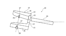
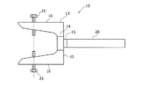
実施形態では、このような不都合を防止するために、図3から図5を用いて示す主ロープロッド回転防止治具10が用いられる。以下では、主ロープロッド回転防止治具10は、回転防止治具10と記載する。図3は、回転防止治具10の斜視図である。図4は、回転防止治具10を上方から見た図である。図5は、回転防止治具10の正面図である。図6は、図5において、軸部20とU字形部11とを分離して示す図である。   In the embodiment, in order to prevent such inconvenience, the main rope rod rotation preventing jig 10 shown in FIGS. 3 to 5 is used. Hereinafter, the main rope rod rotation preventing jig 10 is referred to as a rotation preventing jig 10. FIG. 3 is a perspective view of the rotation preventing jig 10. FIG. 4 is a view of the rotation preventing jig 10 as viewed from above. FIG. 5 is a front view of the rotation preventing jig 10. FIG. 6 is a view showing the shaft section 20 and the U-shaped section 11 separately in FIG.

回転防止治具10は、複数の主ロープ50とカウンタウェイト60との接続部における各主ロープ50の張力調整に用いられる。回転防止治具10は、U字形部11と、軸部20と、2つのボルト25とを備える。U字形部11は、主ロープ50の端部に接続されたウェイト側ロッド部材70の外側に嵌めるものである。具体的には、U字形部11は、ベース部12と、2つの略平行な腕部16とを有し、U字形に形成される。ベース部12は、2つの腕部16の間に連結される連結板部13と、連結板部13の長手方向中間部で幅方向一方側面(図3、図4の紙面の表側面、図5の上側面)から突出する突出板部14と、軸固定部15とを有する。軸固定部15は、突出板部14の一方側面(図4、図5の右側面)から突出するように形成される。軸固定部15は、先端面(図3〜図5の右側面)にネジ孔(図示せず)が形成される。例えば、軸固定部15は、突出板部14の一方側面にナットを溶接固定することにより形成される。軸固定部15は、後述する軸部20の端部をネジ結合により固定する。   The rotation preventing jig 10 is used for adjusting the tension of each of the main ropes 50 at a connection portion between the plurality of main ropes 50 and the counterweight 60. The rotation preventing jig 10 includes a U-shaped part 11, a shaft part 20, and two bolts 25. The U-shaped portion 11 fits outside the weight-side rod member 70 connected to the end of the main rope 50. Specifically, the U-shaped part 11 has a base part 12 and two substantially parallel arms 16 and is formed in a U-shape. The base portion 12 includes a connecting plate portion 13 connected between the two arm portions 16 and one side in the width direction at the middle portion in the longitudinal direction of the connecting plate portion 13 (the front side of the paper in FIGS. 3 and 4; And a shaft fixing portion 15. The shaft fixing portion 15 is formed so as to protrude from one side surface (the right side surface in FIGS. 4 and 5) of the protruding plate portion 14. The shaft fixing portion 15 has a screw hole (not shown) formed on a front end surface (the right side surface in FIGS. 3 to 5). For example, the shaft fixing portion 15 is formed by fixing a nut to one side surface of the protruding plate portion 14 by welding. The shaft fixing portion 15 fixes an end of a shaft portion 20 described later by screw connection.

2つの腕部16は、連結板部13の両端部において、軸固定部15と反対側である同方向(図3〜図5の左方向)に突出するように結合される。各腕部16は、断面が略三角形であり、先端に向かうほど幅狭となっている。また、各腕部16の長手方向中間部には、後述するボルト25をねじ結合するためのねじ孔17が形成される。2つの腕部16の間隔は、主ロープ50に結合されたウェイト側ロッド部材70の接続ピン75(図2)の全長よりも大きい。これにより、2つの腕部16の内側にはウェイト側ロッド部材70が配置可能である。また、2つの腕部16に形成されたねじ孔17は、一直線状に配置される。このため、各ねじ孔17にボルト25がねじ込まれた状態で、ボルト25の先端が対面する。図2に戻って示すように、回転防止治具10の各腕部16の内側からボルト25の先端が突出し、それらの先端がウェイト側ロッド部材70の接続ピン75の端面中心部に突き当て可能である。   The two arm portions 16 are coupled at both ends of the connecting plate portion 13 so as to protrude in the same direction (the left direction in FIGS. 3 to 5) opposite to the shaft fixing portion 15. Each of the arms 16 has a substantially triangular cross section, and becomes narrower toward the tip. A screw hole 17 for screwing a bolt 25 to be described later is formed in a longitudinally intermediate portion of each arm 16. The distance between the two arms 16 is greater than the entire length of the connection pin 75 (FIG. 2) of the weight-side rod member 70 connected to the main rope 50. Thereby, the weight side rod member 70 can be arranged inside the two arm portions 16. The screw holes 17 formed in the two arms 16 are arranged in a straight line. Therefore, in a state where the bolt 25 is screwed into each screw hole 17, the tip of the bolt 25 faces. As shown in FIG. 2, the tips of the bolts 25 project from the inside of each arm 16 of the rotation preventing jig 10, and those tips can abut the center of the end face of the connection pin 75 of the weight-side rod member 70. It is.

図3から図6に示すように、回転防止治具10の軸部20は、ベース部12において、腕部16と反対方向に突出するように固定される。具体的には、軸部20は、直線状に伸びる円柱状、または一端(図3〜図6の左端)が塞がれた円筒状である。そして、図7に示すように、軸部20の一端面には軸方向に突出するおねじ部21が形成される。そしてこのおねじ部21をU字形部11の軸固定部15にネジ結合することにより、軸部20がU字形部11に対しネジ結合により分離可能に固定される。この状態で軸部20は、ベース部12から、腕部16と反対方向に突出する。U字形部11及び軸部20は、例えば鉄等の金属により形成される。   As shown in FIGS. 3 to 6, the shaft portion 20 of the rotation preventing jig 10 is fixed to the base portion 12 so as to protrude in the direction opposite to the arm portion 16. Specifically, the shaft portion 20 has a columnar shape extending linearly or a cylindrical shape having one end (the left end in FIGS. 3 to 6) closed. Then, as shown in FIG. 7, a male screw portion 21 protruding in the axial direction is formed on one end surface of the shaft portion 20. Then, by screwing the external thread portion 21 to the shaft fixing portion 15 of the U-shaped portion 11, the shaft portion 20 is separably fixed to the U-shaped portion 11 by screw connection. In this state, the shaft portion 20 protrudes from the base portion 12 in a direction opposite to the arm portion 16. The U-shaped part 11 and the shaft part 20 are formed of a metal such as iron, for example.

2つのボルト25は、2つの腕部16のそれぞれに、外側からねじ込むように結合され、2つのボルト25の先端部は、2つの腕部16の内側であるウェイト側ロッド部材70側に突出している。そして、各ボルト25の先端部を、対応する腕部16にウェイト側ロッド部材70側に突出させるようにねじ込むことで、ウェイト側ロッド部材70の接続ピン75(図2)の端面に突き当て可能としている。   The two bolts 25 are coupled to each of the two arms 16 so as to be screwed in from the outside, and the tips of the two bolts 25 protrude toward the weight-side rod member 70 that is inside the two arms 16. I have. Then, the distal end of each bolt 25 is screwed into the corresponding arm 16 so as to protrude toward the weight-side rod member 70, so that the end face of the connection pin 75 (FIG. 2) of the weight-side rod member 70 can be abutted. And

図7は、カウンタウェイト60(図1)の上部に接続された複数のウェイト側ロッド部材70のうち、1つのウェイト側ロッド部材70に回転防止治具10を固定して、そのウェイト側ロッド部材70の回り止めを行う作業を工程順に示す図である。   FIG. 7 shows a state in which the rotation preventing jig 10 is fixed to one of the weight-side rod members 70 connected to the upper part of the counterweight 60 (FIG. 1), It is a figure which shows the operation | work which performs the rotation stop of 70 in order of process.

図7(a)に示すように、カウンタウェイト60の上側では、複数のウェイト側ロッド部材70が密集した状態で上方に突き出しており、それぞれに主ロープに接続されたロープ側ロッド部材51が結合されている。そして、図7(b)に示すように回転防止の対象である1つのウェイト側ロッド部材70の上端部には、回転防止治具10のU字形部11が、軸部20と分離した状態で結合固定される。具体的には、1つのウェイト側ロッド部材70の上端部に設けられ、ロープ側ロッド部材51の先端部から横方向に突出する接続ピン75を囲うように、U字形部11が配置される。そして、この状態で、U字形部11の各腕部16にボルト25をねじ込んで、各腕部16から内側に突出したボルト25の先端部が接続ピン75の両端面に突き当てられ、2つのボルト25が接続ピン75を両側から挟む。これにより、U字形部11がウェイト側ロッド部材70に固定される。   As shown in FIG. 7A, a plurality of weight-side rod members 70 protrude upward in a dense state above the counterweight 60, and a rope-side rod member 51 connected to the main rope is connected to each. Have been. Then, as shown in FIG. 7B, the U-shaped part 11 of the rotation preventing jig 10 is separated from the shaft part 20 at the upper end of one weight-side rod member 70 to be prevented from rotating. The connection is fixed. Specifically, the U-shaped portion 11 is provided so as to surround a connection pin 75 provided at the upper end of one weight-side rod member 70 and protruding laterally from the tip of the rope-side rod member 51. Then, in this state, a bolt 25 is screwed into each arm 16 of the U-shaped part 11, and the tip of the bolt 25 protruding inward from each arm 16 abuts against both end surfaces of the connection pin 75, and The bolt 25 sandwiches the connection pin 75 from both sides. Thereby, the U-shaped part 11 is fixed to the weight side rod member 70.

次いで、図7(c)に示すように、U字形部11に軸部20がネジ結合されることにより、U字形部11と軸部20とが固定される。この状態で、軸部20は、他の複数の主ロープ50の端部に接続された複数のウェイト側ロッド部材70またはロープ側ロッド部材51の間に配置されて横方向に伸びている。これにより、軸部20は、他の主ロープに接続されたロープ側ロッド部材51、またはこのロープ側ロッド部材51に接続されたウェイト側ロッド部材70に接触するか、または隙間を介して面している。   Next, as shown in FIG. 7C, the shaft portion 20 is screwed to the U-shaped portion 11, whereby the U-shaped portion 11 and the shaft portion 20 are fixed. In this state, the shaft portion 20 is disposed between the plurality of weight side rod members 70 or the rope side rod members 51 connected to the ends of the other plurality of main ropes 50 and extends in the lateral direction. Thereby, the shaft portion 20 comes into contact with the rope-side rod member 51 connected to another main rope or the weight-side rod member 70 connected to the rope-side rod member 51, or faces through a gap. ing.

上記のように、回転防止治具10は、腕部16にボルト25の先端部をウェイト側ロッド部材70側に突出させるようにねじ込んで、ウェイト側ロッド部材70に突き当てることにより、ウェイト側ロッド部材70に回転防止治具10を保持できる。そして、この状態で回転防止治具10の軸部20が他の主ロープ50に接続されたロープ側ロッド部材51、またはこのロープ側ロッド部材51に接続されたウェイト側ロッド部材70に係合する。これにより、回転防止治具10が固定されたウェイト側ロッド部材70及び主ロープ50の回り止めを行える。また、このとき、ウェイト側ロッド部材70に治具を挿入したり、ウェイト側ロッド部材70のねじ部に治具をねじ係合する必要がない。回転防止治具10は、軸部20を水平方向に対し傾斜させることにより、主ロープ50に接続された周囲のロープ側ロッド部材51に係合可能に配置されてもよい。   As described above, the rotation-preventing jig 10 is screwed into the arm 16 so that the tip of the bolt 25 projects toward the weight-side rod member 70, and is brought into contact with the weight-side rod member 70. The member 70 can hold the rotation preventing jig 10. Then, in this state, the shaft portion 20 of the rotation preventing jig 10 is engaged with the rope side rod member 51 connected to another main rope 50 or the weight side rod member 70 connected to this rope side rod member 51. . Thereby, the rotation of the weight side rod member 70 and the main rope 50 to which the rotation preventing jig 10 is fixed can be prevented. At this time, there is no need to insert a jig into the weight-side rod member 70 or to screw-engage the jig with the threaded portion of the weight-side rod member 70. The rotation preventing jig 10 may be disposed so as to be able to engage with the surrounding rope side rod member 51 connected to the main rope 50 by inclining the shaft portion 20 with respect to the horizontal direction.

なお、本例と異なる比較例として、ウェイト側ロッド部材70のナット73の位置を調節する際に、1つのウェイト側ロッド部材70をスパナで挟んで保持させる方法も考えられる。この方法では、スパナにおいて、挟み部とは反対側の掴み部を他のウェイト側ロッド部材70に対面させて係合可能とする。しかしながらこの場合には、スパナの挟み部とウェイト側ロッド部材70との間には比較的大きな隙間が発生するので、ウェイト側ロッド部材70にスパナを十分な固定強度で固定することは難しい。また、その固定はスパナ本来の機能ではないので固定作業に適さずスパナを痛める原因となる。実施形態では、このような不都合を防止できる。   As a comparative example different from this example, a method of holding one weight-side rod member 70 with a spanner when adjusting the position of the nut 73 of the weight-side rod member 70 is also conceivable. According to this method, in the wrench, the gripping portion opposite to the holding portion faces the other weight side rod member 70 so as to be engageable. However, in this case, since a relatively large gap is generated between the sandwiched portion of the spanner and the weight side rod member 70, it is difficult to fix the spanner to the weight side rod member 70 with sufficient fixing strength. In addition, since the fixing is not an original function of the spanner, it is not suitable for the fixing operation and causes a damage to the spanner. In the embodiment, such inconvenience can be prevented.

さらに、実施形態では、軸部20は、U字形部11に対しネジ結合により分離可能に固定されるので、上記の図7(b)に示したように、U字形部11を軸部20とは分離してウェイト側ロッド部材70に固定することができる。そして、その後で、U字形部11に軸部20を固定できる。これにより、複数のウェイト側ロッド部材70の間に回転防止治具10の全体を外側から挿入できない、または挿入しにくい場合でも、U字形部11だけを先に複数のウェイト側ロッド部材70の間に容易に配置できる。例えば、複数のウェイト側ロッド部材70が小さい間隔をあけて密集しており、軸部20とU字形部11とが一体化された状態では回転防止治具10を複数のウェイト側ロッド部材70の間に配置できない場合がある。この場合には、U字形部11を先にウェイト側ロッド部材70に固定する。そして、その後で、軸部20だけを複数のウェイト側ロッド部材70の間に横方向一方側(図7(c)の左側)等から容易に差し込んで、U字形部11に軸部20を結合することができる。これにより、回転防止治具10の固定作業の作業性を高くできる。   Further, in the embodiment, since the shaft portion 20 is fixed to the U-shaped portion 11 so as to be separable by screw connection, the U-shaped portion 11 is connected to the shaft portion 20 as shown in FIG. Can be separated and fixed to the weight side rod member 70. After that, the shaft portion 20 can be fixed to the U-shaped portion 11. Accordingly, even when the entire rotation preventing jig 10 cannot be inserted from the outside or is difficult to be inserted between the plurality of weight side rod members 70, only the U-shaped portion 11 is first inserted between the plurality of weight side rod members 70. Can be easily arranged. For example, the plurality of weight-side rod members 70 are densely spaced at small intervals, and when the shaft portion 20 and the U-shaped portion 11 are integrated, the rotation preventing jig 10 is moved to the plurality of weight-side rod members 70. It may not be possible to place them between them. In this case, the U-shaped part 11 is fixed to the weight side rod member 70 first. After that, only the shaft portion 20 is easily inserted between the plurality of weight-side rod members 70 from one side in the lateral direction (the left side in FIG. 7C) or the like, and the shaft portion 20 is coupled to the U-shaped portion 11. can do. Thereby, the workability of the fixing work of the rotation preventing jig 10 can be improved.

また、2つのボルト25は、2つの腕部16のそれぞれにねじ込むように結合され、2つのボルト25の先端部は、2つの腕部16のウェイト側ロッド部材70側に突出している。これにより、回転防止治具10をウェイト側ロッド部材70に固定する際の微調整を容易に行える。例えば2つの腕部16の内側からのボルト25の突出量を、2つのボルト25の間で変えることもできる。   Further, the two bolts 25 are coupled so as to be screwed into each of the two arm portions 16, and the tip portions of the two bolts 25 project toward the weight-side rod member 70 of the two arm portions 16. Thereby, fine adjustment when fixing the rotation preventing jig 10 to the weight side rod member 70 can be easily performed. For example, the amount of protrusion of the bolt 25 from the inside of the two arms 16 can be changed between the two bolts 25.

図8は、実施形態の別例の回転防止治具10を構成するキャップ30を示す図である。図9は、キャップ30をウェイト側ロッド部材70の接続ピン75の端部に嵌合させて、回転防止治具10のボルト25の先端部を接続ピン75の端面に突き当てた状態を示す断面図である。図10は、図9を上方から見た図である。   FIG. 8 is a diagram illustrating a cap 30 that constitutes the rotation preventing jig 10 according to another example of the embodiment. FIG. 9 is a cross-sectional view showing a state in which the cap 30 is fitted to the end of the connection pin 75 of the weight-side rod member 70 and the tip of the bolt 25 of the rotation preventing jig 10 abuts against the end face of the connection pin 75. FIG. FIG. 10 is a view of FIG. 9 as viewed from above.

図8から図10に示す別例の構成では、回転防止治具10をウェイト側ロッド部材70に固定する際に、回転防止治具10のボルト25の先端部にキャップ30を嵌合させている。図8に示すように、キャップ30は、直方体の一端が開口する略箱形であり、周壁部31を形成する2つの対面する板部32の開口端に切欠33が形成される。図8では、対面する2つの板部32のうち、1つの(図8の上側の)板部32に形成された切欠33が示されている。ウェイト側ロッド部材70に回転防止治具10が固定された状態で、切欠33の内側には、接続ピン75から突出する割ピン76(図9、図10)の端部が配置される。図8では、切欠33を半円形としているが、矩形等の別の形状でもよい。また、キャップ30を形成する底板部34の中心部には、貫通孔35が形成されている。貫通孔35の直径は、回転防止治具10のボルト25のねじ部の外径とほぼ同じである。   In the configuration of another example shown in FIGS. 8 to 10, when fixing the rotation preventing jig 10 to the weight side rod member 70, the cap 30 is fitted to the tip of the bolt 25 of the rotation preventing jig 10. . As shown in FIG. 8, the cap 30 has a substantially box shape with one end of a rectangular parallelepiped opened, and a notch 33 is formed at an opening end of two facing plate portions 32 forming the peripheral wall portion 31. FIG. 8 shows a cutout 33 formed in one (upper side in FIG. 8) plate portion 32 of the two facing plate portions 32. With the rotation preventing jig 10 fixed to the weight side rod member 70, an end of a split pin 76 (FIGS. 9 and 10) protruding from the connection pin 75 is arranged inside the notch 33. In FIG. 8, the notch 33 is semicircular, but may have another shape such as a rectangle. Further, a through hole 35 is formed in the center of the bottom plate portion 34 forming the cap 30. The diameter of the through hole 35 is substantially the same as the outer diameter of the thread portion of the bolt 25 of the rotation preventing jig 10.

図9、図10に示すように、回転防止治具10をウェイト側ロッド部材70に固定する際には、回転防止治具10の各腕部16から内側に突出するボルト25の先端部にキャップ30を嵌合させる。このとき、キャップ30の切欠33の内側には、接続ピン75に挿入された割ピン76の端部が通ってキャップ30との干渉が防止される。また、ボルト25の先端部は、底板部34の外側から貫通孔35を通ってキャップ30の内側に挿入される。そして、キャップ30の周壁部31が、ウェイト側ロッド部材70の円柱状の接続ピン75の端部に嵌合される。この状態で、切欠33を有する2つの板部32の間隔D(図9)は、接続ピン75の端部の外径とほぼ同じである。これにより、接続ピン75の端部に対し、キャップ30が直径方向にずれ動くことが抑制される。そして、キャップ30の内側に突出するボルト25の先端部を、接続ピン75の端面のほぼ中心に容易に突き当てることができる。このため、接続ピン75の軸方向両端のほぼ中心にそれぞれボルト25の先端を突き当てて締め付けることで、回転防止治具10をウェイト側ロッド部材70に、容易に安定して固定することができる。その他の構成及び作用は、図1から図7の構成と同様である。   As shown in FIGS. 9 and 10, when fixing the rotation-preventing jig 10 to the weight-side rod member 70, a cap is attached to the tip of a bolt 25 projecting inward from each arm 16 of the rotation-preventing jig 10. 30 is fitted. At this time, the end of the split pin 76 inserted into the connection pin 75 passes through the inside of the notch 33 of the cap 30 to prevent interference with the cap 30. The tip of the bolt 25 is inserted from the outside of the bottom plate portion 34 into the inside of the cap 30 through the through hole 35. Then, the peripheral wall 31 of the cap 30 is fitted to the end of the cylindrical connection pin 75 of the weight-side rod member 70. In this state, the distance D (FIG. 9) between the two plate portions 32 having the cutouts 33 is substantially the same as the outer diameter of the end of the connection pin 75. Accordingly, the cap 30 is prevented from moving in the diametrical direction with respect to the end of the connection pin 75. Then, the tip of the bolt 25 protruding inside the cap 30 can be easily butted against substantially the center of the end face of the connection pin 75. For this reason, the rotation prevention jig 10 can be easily and stably fixed to the weight side rod member 70 by abutting the tips of the bolts 25 to the centers of both ends in the axial direction of the connection pins 75 and tightening them. . Other configurations and operations are the same as those in the configurations of FIGS. 1 to 7.

図11は、キャップ30の別例を、ウェイト側ロッド部材70の接続ピン75の端部に嵌合させた状態を示している図9に対応する図である。図11に示す回転防止治具10では、図8から図10の構成において、ボルト25の周囲で、キャップ30の底板部34と腕部16との間に配置されたコイルバネ36を備える。そして、コイルバネ36の縮みによる反発力が底板部34及び腕部16に加わっている。   FIG. 11 is a view corresponding to FIG. 9, showing a state in which another example of the cap 30 is fitted to the end of the connection pin 75 of the weight side rod member 70. The rotation preventing jig 10 shown in FIG. 11 includes a coil spring 36 disposed between the bottom plate portion 34 of the cap 30 and the arm portion 16 around the bolt 25 in the configuration shown in FIGS. Then, a repulsive force due to the contraction of the coil spring 36 is applied to the bottom plate portion 34 and the arm portion 16.

上記構成によれば、コイルバネ36によって、キャップ30が腕部16に対し接続ピン75の中心軸を中心とする回転方向等にずれ動くことを抑制できる。これにより、ボルト25の先端部を接続ピン75の端面のほぼ中心に、より容易に突き当てることができる。その他の構成及び作用は、図8から図10の構成と同様である。   According to the above configuration, the coil spring 36 can suppress the cap 30 from being shifted with respect to the arm 16 in a rotational direction or the like about the center axis of the connection pin 75. Thus, the tip of the bolt 25 can be more easily brought into contact with the approximate center of the end face of the connection pin 75. Other configurations and operations are the same as the configurations in FIGS. 8 to 10.

なお、上記の各例の構成では、回転防止治具10の2つの腕部16の両方にボルト25をねじ込んだ構成を説明したが、1つの腕部16のみにボルト25がねじ込まれる構成としてもよい。このとき、ボルト25の先端部と、ボルト25がねじ込まれない他の腕部16とでウェイト側ロッド部材70が挟まれて、回転防止治具10をウェイト側ロッド部材70に固定することができる。このとき、回転防止治具10の軸部20は、2つの腕部16の一方側、例えばボルト25がねじ込まれる腕部16の側に偏った状態で、U字形部11に固定されてもよい。   In the configuration of each example described above, the configuration in which the bolt 25 is screwed into both of the two arms 16 of the rotation preventing jig 10 has been described, but the configuration in which the bolt 25 is screwed into only one arm 16 may be used. Good. At this time, the weight-side rod member 70 is sandwiched between the tip portion of the bolt 25 and the other arm portion 16 to which the bolt 25 is not screwed, and the rotation preventing jig 10 can be fixed to the weight-side rod member 70. . At this time, the shaft portion 20 of the rotation preventing jig 10 may be fixed to the U-shaped portion 11 in a state where the shaft portion 20 is biased to one side of the two arms 16, for example, the side of the arm 16 into which the bolt 25 is screwed. .

また、上記では、回転防止治具10がウェイト側ロッド部材70に固定される場合を説明したが、回転防止治具はロープ側ロッド部材51に固定される構成としてもよい。   In the above description, the case where the rotation preventing jig 10 is fixed to the weight side rod member 70 has been described, but the rotation preventing jig may be fixed to the rope side rod member 51.

10 主ロープロッド回転防止治具(回転防止治具)、11 U字形部、12 ベース部、13 連結板部、14 突出板部、15 軸固定部、16 腕部、17 ねじ孔、20 軸部、21 おねじ部、25 ボルト、30 キャップ、31 周壁部、32 板部、33 切欠、34 底板部、35 貫通孔、36 コイルバネ、40 エレベータ、41 昇降路、42 カウンタレール、50 主ロープ、51 ロープ側ロッド部材、52 腕部、60 カウンタウェイト、61 枠体、61a 上端板部、62 錘、63 ガイドシュー、70 ウェイト側ロッド部材、70a 頭部、71 ロッド本体、72 おねじ部、73 ナット、75 接続ピン、76 割ピン。   Reference Signs List 10 Main rope rod rotation prevention jig (rotation prevention jig), 11 U-shaped part, 12 base part, 13 connecting plate part, 14 projecting plate part, 15 shaft fixing part, 16 arm part, 17 screw hole, 20 shaft part , 21 male thread, 25 bolt, 30 cap, 31 peripheral wall, 32 plate, 33 notch, 34 bottom plate, 35 through hole, 36 coil spring, 40 elevator, 41 hoistway, 42 counter rail, 50 main rope, 51 Rope side rod member, 52 arms, 60 counterweight, 61 frame, 61a upper end plate, 62 weight, 63 guide shoe, 70 weight side rod member, 70a head, 71 rod body, 72 male thread, 73 nut , 75 connection pins, 76 split pins.

Claims (3)

エレベータの複数の主ロープとカウンタウェイトとの接続部における前記主ロープの張力調整に用いられる主ロープロッド回転防止治具であって、
前記主ロープの前記カウンタウェイト側端部に接続されたロッド部材の外側に嵌めるU字形部であり、ベース部及び前記ベース部の両端部に結合された2つの腕部を含むU字形部と、前記ベース部に前記腕部と反対方向に突出するように固定された軸部と、前記2つの腕部の少なくとも一方の前記腕部に結合されたボルトとを備え、
前記一方の腕部において、前記ボルトの先端部を前記ロッド部材側に突出させるようにねじ込むことで前記ロッド部材に突き当て可能に構成され、
前記軸部は、前記ベース部に対しネジ結合により分離可能に固定されている、
主ロープロッド回転防止治具。
A main rope rod rotation preventing jig used for adjusting tension of the main rope at a connection portion between a plurality of main ropes and a counter weight of an elevator,
A U-shaped portion fitted to the outside of a rod member connected to the counterweight side end portion of the main rope, the U-shaped portion including a base portion and two arms coupled to both ends of the base portion; A shaft portion fixed to the base portion so as to protrude in a direction opposite to the arm portion, and a bolt coupled to the arm portion of at least one of the two arm portions,
In the one arm portion, the distal end of the bolt is screwed so as to protrude toward the rod member, and is configured to be able to abut against the rod member ,
The shank, that are detachably fixed by a screw attached to said base portion,
Main rope rod rotation prevention jig.
請求項1に記載の主ロープロッド回転防止治具において、
前記ロッド部材に前記ボルトの先端部が突き当てられた状態で、前記軸部は、前記複数の主ロープのうち、他の前記主ロープの前記カウンタウェイト側端部に接続されたロッド部材に係合可能に接触または隙間を介して面する、主ロープロッド回転防止治具。
The jig for preventing rotation of the main rope rod according to claim 1,
In a state where the tip of the bolt is abutted against the rod member, the shaft portion is engaged with a rod member connected to the counterweight side end of another main rope of the plurality of main ropes. A main rope rod rotation prevention jig that faces through a contact or gap if possible.
請求項1または請求項2に記載の主ロープロッド回転防止治具において、
前記ボルトは、前記2つの腕部のそれぞれにねじ込むように結合された2つのボルトであり、
前記2つのボルトの先端部は、前記2つの腕部の前記ロッド部材側に突出している、主ロープロッド回転防止治具。
In the main rope rod rotation preventing jig according to claim 1 or 2 ,
The bolts are two bolts screwed into each of the two arms,
A main rope rod rotation preventing jig, wherein tips of the two bolts protrude toward the rod member of the two arms.
JP2016036591A 2016-02-29 2016-02-29 Main rope rod rotation prevention jig Active JP6643143B2 (en)

Priority Applications (1)

Application Number Priority Date Filing Date Title
JP2016036591A JP6643143B2 (en) 2016-02-29 2016-02-29 Main rope rod rotation prevention jig

Applications Claiming Priority (1)

Application Number Priority Date Filing Date Title
JP2016036591A JP6643143B2 (en) 2016-02-29 2016-02-29 Main rope rod rotation prevention jig

Publications (2)

Publication Number Publication Date
JP2017154825A JP2017154825A (en) 2017-09-07
JP6643143B2 true JP6643143B2 (en) 2020-02-12

Family

ID=59807965

Family Applications (1)

Application Number Title Priority Date Filing Date
JP2016036591A Active JP6643143B2 (en) 2016-02-29 2016-02-29 Main rope rod rotation prevention jig

Country Status (1)

Country Link
JP (1) JP6643143B2 (en)

Families Citing this family (2)

* Cited by examiner, † Cited by third party
Publication number Priority date Publication date Assignee Title
KR102414344B1 (en) 2017-08-09 2022-06-29 스미또모 덴꼬 쇼오께쯔 고오낑 가부시끼가이샤 joint parts
WO2021130887A1 (en) * 2019-12-25 2021-07-01 三菱電機ビルテクノサービス株式会社 Rotation stopper for elevator rope and method for adjusting tension in elevator rope

Family Cites Families (3)

* Cited by examiner, † Cited by third party
Publication number Priority date Publication date Assignee Title
JPS5114900U (en) * 1974-07-17 1976-02-03
JP2542833Y2 (en) * 1991-09-24 1997-07-30 株式会社日立ビルシステム Elevator rope detent tool
JPH0683233U (en) * 1993-05-14 1994-11-29 株式会社芦田製作所 Vise

Also Published As

Publication number Publication date
JP2017154825A (en) 2017-09-07

Similar Documents

Publication Publication Date Title
MX2012005605A (en) Base frame for a lifting apparatus, especially a cable traction mechanism, comprising connecting possibilities.
JP6643143B2 (en) Main rope rod rotation prevention jig
KR20160041968A (en) Anchor bolt
JP6307371B2 (en) Hole hanging clamp
JP2011063433A (en) Rail bracket for elevator
WO2015145669A1 (en) Fixing device and fixing method for elevator guide rail
EP3715304B1 (en) Rope end fastening device and rope end fastening method
JP5235380B2 (en) Elevator cab and nut screwing tool
JP5569193B2 (en) Elevator guide rail clip tightening jig
JP7296782B2 (en) Whirl-stop
JP5225872B2 (en) Hanging wire bracket
JP2018091425A (en) Mounting bracket and bird net fixture
JP3225269U (en) Hanging piece
JPWO2020240656A1 (en) Installation jig and installation method for wedge type rope terminal parts
JP5521636B2 (en) Elevator main rope terminal device
CN211073260U (en) Fixing device for rod
JP2012250821A (en) Elevator
JP5578904B2 (en) Automatic screwing machine
JP6222861B1 (en) Rail bracket and fixing method of rail bracket
JP4061182B2 (en) Sliding door suspension
JP3128814U (en) Tripod attachment for PAT connection machine
JP2015037991A (en) Workpiece hanging jig
JP2024132494A (en) Fixture for attaching a cord to a wedge-type fastening device
JP3681600B2 (en) Elevator main rope end adjustment jig
JP2002265166A (en) Adjustment jig for elevator main rope end

Legal Events

Date Code Title Description
A621 Written request for application examination

Free format text: JAPANESE INTERMEDIATE CODE: A621

Effective date: 20181116

A977 Report on retrieval

Free format text: JAPANESE INTERMEDIATE CODE: A971007

Effective date: 20190917

A131 Notification of reasons for refusal

Free format text: JAPANESE INTERMEDIATE CODE: A131

Effective date: 20190924

A521 Request for written amendment filed

Free format text: JAPANESE INTERMEDIATE CODE: A523

Effective date: 20191121

TRDD Decision of grant or rejection written
A01 Written decision to grant a patent or to grant a registration (utility model)

Free format text: JAPANESE INTERMEDIATE CODE: A01

Effective date: 20191203

A61 First payment of annual fees (during grant procedure)

Free format text: JAPANESE INTERMEDIATE CODE: A61

Effective date: 20200106

R150 Certificate of patent or registration of utility model

Ref document number: 6643143

Country of ref document: JP

Free format text: JAPANESE INTERMEDIATE CODE: R150

S533 Written request for registration of change of name

Free format text: JAPANESE INTERMEDIATE CODE: R313533

R350 Written notification of registration of transfer

Free format text: JAPANESE INTERMEDIATE CODE: R350

R250 Receipt of annual fees

Free format text: JAPANESE INTERMEDIATE CODE: R250

R250 Receipt of annual fees

Free format text: JAPANESE INTERMEDIATE CODE: R250

R250 Receipt of annual fees

Free format text: JAPANESE INTERMEDIATE CODE: R250