JP6673404B2 - 導電部材 - Google Patents
導電部材 Download PDFInfo
- Publication number
- JP6673404B2 JP6673404B2 JP2018122650A JP2018122650A JP6673404B2 JP 6673404 B2 JP6673404 B2 JP 6673404B2 JP 2018122650 A JP2018122650 A JP 2018122650A JP 2018122650 A JP2018122650 A JP 2018122650A JP 6673404 B2 JP6673404 B2 JP 6673404B2
- Authority
- JP
- Japan
- Prior art keywords
- conductor
- conductive member
- flexible conductor
- terminal
- flexible
- Prior art date
- Legal status (The legal status is an assumption and is not a legal conclusion. Google has not performed a legal analysis and makes no representation as to the accuracy of the status listed.)
- Expired - Fee Related
Links
- 239000004020 conductor Substances 0.000 title claims description 88
- 239000011248 coating agent Substances 0.000 claims description 18
- 238000000576 coating method Methods 0.000 claims description 18
- 229910052751 metal Inorganic materials 0.000 claims description 15
- 239000002184 metal Substances 0.000 claims description 15
- 230000002093 peripheral effect Effects 0.000 claims description 13
- 239000003566 sealing material Substances 0.000 claims description 8
- XLYOFNOQVPJJNP-UHFFFAOYSA-N water Substances O XLYOFNOQVPJJNP-UHFFFAOYSA-N 0.000 claims description 6
- 230000000903 blocking effect Effects 0.000 claims description 3
- 238000009413 insulation Methods 0.000 claims description 2
- 238000002788 crimping Methods 0.000 description 43
- 238000005452 bending Methods 0.000 description 9
- 238000000034 method Methods 0.000 description 8
- 238000004519 manufacturing process Methods 0.000 description 7
- 229910000679 solder Inorganic materials 0.000 description 7
- 230000000694 effects Effects 0.000 description 5
- 239000010410 layer Substances 0.000 description 5
- 239000012790 adhesive layer Substances 0.000 description 4
- 238000005516 engineering process Methods 0.000 description 4
- 238000010438 heat treatment Methods 0.000 description 4
- 238000007747 plating Methods 0.000 description 4
- 229910000838 Al alloy Inorganic materials 0.000 description 3
- 229910000881 Cu alloy Inorganic materials 0.000 description 3
- ATJFFYVFTNAWJD-UHFFFAOYSA-N Tin Chemical compound [Sn] ATJFFYVFTNAWJD-UHFFFAOYSA-N 0.000 description 3
- 230000014759 maintenance of location Effects 0.000 description 3
- 239000000463 material Substances 0.000 description 3
- 239000007787 solid Substances 0.000 description 3
- 238000003466 welding Methods 0.000 description 3
- RYGMFSIKBFXOCR-UHFFFAOYSA-N Copper Chemical compound [Cu] RYGMFSIKBFXOCR-UHFFFAOYSA-N 0.000 description 2
- 229910052782 aluminium Inorganic materials 0.000 description 2
- XAGFODPZIPBFFR-UHFFFAOYSA-N aluminium Chemical compound [Al] XAGFODPZIPBFFR-UHFFFAOYSA-N 0.000 description 2
- 238000005219 brazing Methods 0.000 description 2
- 230000008602 contraction Effects 0.000 description 2
- 229910052802 copper Inorganic materials 0.000 description 2
- 239000010949 copper Substances 0.000 description 2
- 238000003780 insertion Methods 0.000 description 2
- 230000037431 insertion Effects 0.000 description 2
- 239000011347 resin Substances 0.000 description 2
- 229920005989 resin Polymers 0.000 description 2
- 239000000853 adhesive Substances 0.000 description 1
- 230000001070 adhesive effect Effects 0.000 description 1
- 238000009954 braiding Methods 0.000 description 1
- 238000005520 cutting process Methods 0.000 description 1
- 230000000994 depressogenic effect Effects 0.000 description 1
- JEIPFZHSYJVQDO-UHFFFAOYSA-N iron(III) oxide Inorganic materials O=[Fe]O[Fe]=O JEIPFZHSYJVQDO-UHFFFAOYSA-N 0.000 description 1
- 239000000203 mixture Substances 0.000 description 1
- 230000003647 oxidation Effects 0.000 description 1
- 238000007254 oxidation reaction Methods 0.000 description 1
- 239000012466 permeate Substances 0.000 description 1
- 238000003825 pressing Methods 0.000 description 1
- 238000007789 sealing Methods 0.000 description 1
- 238000010008 shearing Methods 0.000 description 1
- 238000004804 winding Methods 0.000 description 1
Images



Classifications
-
- H—ELECTRICITY
- H01—ELECTRIC ELEMENTS
- H01B—CABLES; CONDUCTORS; INSULATORS; SELECTION OF MATERIALS FOR THEIR CONDUCTIVE, INSULATING OR DIELECTRIC PROPERTIES
- H01B5/00—Non-insulated conductors or conductive bodies characterised by their form
- H01B5/02—Single bars, rods, wires, or strips
-
- H—ELECTRICITY
- H01—ELECTRIC ELEMENTS
- H01B—CABLES; CONDUCTORS; INSULATORS; SELECTION OF MATERIALS FOR THEIR CONDUCTIVE, INSULATING OR DIELECTRIC PROPERTIES
- H01B5/00—Non-insulated conductors or conductive bodies characterised by their form
- H01B5/12—Braided wires or the like
-
- H—ELECTRICITY
- H01—ELECTRIC ELEMENTS
- H01B—CABLES; CONDUCTORS; INSULATORS; SELECTION OF MATERIALS FOR THEIR CONDUCTIVE, INSULATING OR DIELECTRIC PROPERTIES
- H01B5/00—Non-insulated conductors or conductive bodies characterised by their form
- H01B5/06—Single tubes
-
- H—ELECTRICITY
- H01—ELECTRIC ELEMENTS
- H01R—ELECTRICALLY-CONDUCTIVE CONNECTIONS; STRUCTURAL ASSOCIATIONS OF A PLURALITY OF MUTUALLY-INSULATED ELECTRICAL CONNECTING ELEMENTS; COUPLING DEVICES; CURRENT COLLECTORS
- H01R11/00—Individual connecting elements providing two or more spaced connecting locations for conductive members which are, or may be, thereby interconnected, e.g. end pieces for wires or cables supported by the wire or cable and having means for facilitating electrical connection to some other wire, terminal, or conductive member, blocks of binding posts
- H01R11/11—End pieces or tapping pieces for wires, supported by the wire and for facilitating electrical connection to some other wire, terminal or conductive member
- H01R11/12—End pieces terminating in an eye, hook, or fork
-
- H—ELECTRICITY
- H01—ELECTRIC ELEMENTS
- H01R—ELECTRICALLY-CONDUCTIVE CONNECTIONS; STRUCTURAL ASSOCIATIONS OF A PLURALITY OF MUTUALLY-INSULATED ELECTRICAL CONNECTING ELEMENTS; COUPLING DEVICES; CURRENT COLLECTORS
- H01R4/00—Electrically-conductive connections between two or more conductive members in direct contact, i.e. touching one another; Means for effecting or maintaining such contact; Electrically-conductive connections having two or more spaced connecting locations for conductors and using contact members penetrating insulation
- H01R4/02—Soldered or welded connections
- H01R4/023—Soldered or welded connections between cables or wires and terminals
-
- H—ELECTRICITY
- H01—ELECTRIC ELEMENTS
- H01R—ELECTRICALLY-CONDUCTIVE CONNECTIONS; STRUCTURAL ASSOCIATIONS OF A PLURALITY OF MUTUALLY-INSULATED ELECTRICAL CONNECTING ELEMENTS; COUPLING DEVICES; CURRENT COLLECTORS
- H01R4/00—Electrically-conductive connections between two or more conductive members in direct contact, i.e. touching one another; Means for effecting or maintaining such contact; Electrically-conductive connections having two or more spaced connecting locations for conductors and using contact members penetrating insulation
- H01R4/10—Electrically-conductive connections between two or more conductive members in direct contact, i.e. touching one another; Means for effecting or maintaining such contact; Electrically-conductive connections having two or more spaced connecting locations for conductors and using contact members penetrating insulation effected solely by twisting, wrapping, bending, crimping, or other permanent deformation
- H01R4/18—Electrically-conductive connections between two or more conductive members in direct contact, i.e. touching one another; Means for effecting or maintaining such contact; Electrically-conductive connections having two or more spaced connecting locations for conductors and using contact members penetrating insulation effected solely by twisting, wrapping, bending, crimping, or other permanent deformation by crimping
- H01R4/183—Electrically-conductive connections between two or more conductive members in direct contact, i.e. touching one another; Means for effecting or maintaining such contact; Electrically-conductive connections having two or more spaced connecting locations for conductors and using contact members penetrating insulation effected solely by twisting, wrapping, bending, crimping, or other permanent deformation by crimping for cylindrical elongated bodies, e.g. cables having circular cross-section
-
- H—ELECTRICITY
- H01—ELECTRIC ELEMENTS
- H01R—ELECTRICALLY-CONDUCTIVE CONNECTIONS; STRUCTURAL ASSOCIATIONS OF A PLURALITY OF MUTUALLY-INSULATED ELECTRICAL CONNECTING ELEMENTS; COUPLING DEVICES; CURRENT COLLECTORS
- H01R4/00—Electrically-conductive connections between two or more conductive members in direct contact, i.e. touching one another; Means for effecting or maintaining such contact; Electrically-conductive connections having two or more spaced connecting locations for conductors and using contact members penetrating insulation
- H01R4/10—Electrically-conductive connections between two or more conductive members in direct contact, i.e. touching one another; Means for effecting or maintaining such contact; Electrically-conductive connections having two or more spaced connecting locations for conductors and using contact members penetrating insulation effected solely by twisting, wrapping, bending, crimping, or other permanent deformation
- H01R4/18—Electrically-conductive connections between two or more conductive members in direct contact, i.e. touching one another; Means for effecting or maintaining such contact; Electrically-conductive connections having two or more spaced connecting locations for conductors and using contact members penetrating insulation effected solely by twisting, wrapping, bending, crimping, or other permanent deformation by crimping
- H01R4/183—Electrically-conductive connections between two or more conductive members in direct contact, i.e. touching one another; Means for effecting or maintaining such contact; Electrically-conductive connections having two or more spaced connecting locations for conductors and using contact members penetrating insulation effected solely by twisting, wrapping, bending, crimping, or other permanent deformation by crimping for cylindrical elongated bodies, e.g. cables having circular cross-section
- H01R4/184—Electrically-conductive connections between two or more conductive members in direct contact, i.e. touching one another; Means for effecting or maintaining such contact; Electrically-conductive connections having two or more spaced connecting locations for conductors and using contact members penetrating insulation effected solely by twisting, wrapping, bending, crimping, or other permanent deformation by crimping for cylindrical elongated bodies, e.g. cables having circular cross-section comprising a U-shaped wire-receiving portion
-
- H—ELECTRICITY
- H01—ELECTRIC ELEMENTS
- H01R—ELECTRICALLY-CONDUCTIVE CONNECTIONS; STRUCTURAL ASSOCIATIONS OF A PLURALITY OF MUTUALLY-INSULATED ELECTRICAL CONNECTING ELEMENTS; COUPLING DEVICES; CURRENT COLLECTORS
- H01R4/00—Electrically-conductive connections between two or more conductive members in direct contact, i.e. touching one another; Means for effecting or maintaining such contact; Electrically-conductive connections having two or more spaced connecting locations for conductors and using contact members penetrating insulation
- H01R4/70—Insulation of connections
- H01R4/72—Insulation of connections using a heat shrinking insulating sleeve
Landscapes
- Connections Effected By Soldering, Adhesion, Or Permanent Deformation (AREA)
- Insulated Conductors (AREA)
- Non-Insulated Conductors (AREA)
- Details Of Indoor Wiring (AREA)
Description
このため、導電性に優れた金属製のパイプなどの筒状導体を導電体として用い、筒状導体の端末を機器の接続部に直接接続する方法が検討されている。
このような構成によると、車両において形状の保持が必要な部分の配索は、形状が保持可能な筒状導体によって行い、機器周辺など配索スペースが限られた場所の配索は、柔軟性導体によって行うことができるから、外装部材を用いることなく、他の部材の奥や狭いスペースなどに配された機器にも導電部材を接続することができる。また、筒状部材は、中空形状であるため、中実状の導体に比べて導電部材の軽量化を図ることができる。
前記柔軟性導体は、編組線である構成としてもよい。
このような構成によると、複数の素線からなる芯線を絶縁被覆によって被覆した被覆電線に比べて、さらに軽量化を図ると共に、導電部材の配索の自由度を向上させることができる。
このような構成によると、圧着接続部に柔軟導体を挿入し、圧着接続部を外側から押し潰すようにして圧着するだけで、筒状部材と柔軟性導体とを容易に接続することができる。これにより、締結部を設けた筒状部材に柔軟導体を締結部材によって接続したり、筒状部材に柔軟導体を溶接したりする場合に比べて、製造コストを低減することができる。
前記圧着接続部は、前記筒状導体の他の部分に比べて内径寸法が大きく設定されている構成としてもよい。
ところが、このような構成によると、圧着接続部以外の筒状導体の他の部分の断面積を確保しつつ、大径の柔軟性導体と筒状部材とを接続することができる。
前記柔軟導体は筒状に形成されており、前記筒状導体の端部には、前記柔軟導体が被せられた状態で前記柔軟導体に外嵌された金属製の環状部材がかしめ固定される圧着接続部が設けられている構成としてもよい。
このような構成によると、一方の端子から他方の端子までの間が止水被覆によって絶縁および防水される。つまり、両端子間の絶縁性を確保することができるから、導電部材が複数配索される場合に導電部材同士が短絡することを防ぐことができると共に、柔軟性導体と端子との接続部分や柔軟性導体と筒状導体との接続部分に水が浸入して不具合が生じることを防ぐことができる。
このような構成によると、加熱前における筒状部材のチューブ内への挿入は、収縮前の大径なチューブに対して行うことになるため、挿入操作を容易に行うことができる。
このような構成によると、端子から露出した柔軟導体の端部が封止材によって覆われて端子と一体になると共に、止水被覆の端部が端子の外周面に全周に亘って密着しているから、端子と止水被覆との間の隙間や柔軟性導体の端部から水が止水被覆内に進入することを防ぐことができる。
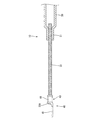
実施形態1について図1から図4を参照して説明する。
本実施形態は、車両の後部に配される図示しないバッテリと車両の前部に設けられたエンジンルームに搭載される図示しない機器とを接続する信号用の導電部材10であって、バッテリとエンジンルームの間における導電部材10の配索経路は、車両の床下とされている。
つまり、本実施形態によると、圧着接続部21の内側に編組線30を配し、圧着接続部21を押し潰すようにして圧着するだけで、パイプ部材20と編組線30とを容易に接続することができる。
まず、丸端子40の圧着部43に編組線30の端部30Aを載置し、一対の圧着片44を編組線30の端部30Aに圧着することで、編組線30の一方の端部30Aに丸端子40を接続する。
編組線30とパイプ部材20を接続する最初の工程としては、編組線30における丸端子40が接続された側とは反対側の他方の端部30Aを、パイプ部材20における圧着接続部21に内挿する。
つまり、本実施形態によると、パイプ部材20の圧着接続部21を編組線30に対して圧着するだけで、パイプ部材20と編組線30とを容易に接続できる。したがって、例えば、編組線に締結端子を接続すると共にパイプ部材に締結部を設けて両者を締結して接続したり、パイプ部材に編組線を溶接して接続したりする場合に比べて、接続作業の工数や製造コストを低減することができる。
熱収縮チューブ50が配置されたところで、加熱処理を行うことで熱収縮チューブ50を熱収縮させる。この加熱処理では、熱収縮チューブ50の両端部が、丸端子40の接続部41における丸孔42と圧着部43との間の部分にほぼ隙間なく密着し、熱収縮チューブ50の中間部分は、編組線30およびパイプ部材20の外周面に隙間なく密着する。これにより、前端の丸端子40の圧着部43から後端の丸端子40の圧着部43までの領域が絶縁されると共に防水された導電部材10が完成する。
ここで、車両の床下に配索されるパイプ部材20は、配索経路に応じて所定の形状に屈曲されてその形状が保持されているから、配索作業を容易にしつつも、外装部材などによる製造コストの増加を抑制することができる。
つまり、本実施形態によると、形状を保持することが必要な部分と柔軟性が必要な部分とで部材を使い分けて配索できるから、外装部材などを用いることに起因した製造コストの増加を抑制しつつ、エンジンルーム内における導電部材10の配索を容易に実施することができる。
また、本実施形態によると、導電部材10の両端部に柔軟性を有する編組線30が設けられているから、車両の走行による振動が導電部材10と機器との間で発生したとしても、編組線30がその振動を吸収し、導電部材10の破損を防ぐことができる。また、編組線30によって機器に接続する際の寸法公差を解消することができる。
次に、実施形態2について図5を参照して説明する。
実施形態2の導電部材110は、実施形態1における熱収縮チューブ50が覆っている領域を変更すると共に、編組線30の端部30Aを半田(「封止材」の一例)60によって覆ったものであって、実施形態1と共通する構成、作用、および効果については重複するため、その説明を省略する。また、実施形態1と同じ構成については同一の符号を用いるものとする。
次に、実施形態3について図6を参照して説明する。
実施形態3の導電部材210は、実施形態1における圧着接続部21の形状を変更すると共に、編組線30を被覆電線230に変更したものであって、実施形態1と共通する構成、作用、および効果については重複するため、その説明を省略する。また、実施形態1と同じ構成については同一の符号を用いるものとする。
そして、圧着接続部221内に被覆電線230の芯線231を挿入し、圧着接続部221を外側から全周に亘ってかしめることで、図6に示すように、圧着接続部221が芯線に固定されると共に電気的に接続されている。
だからといって、板厚寸法が薄いパイプ部材を用いると、導電部材の大型化を防ぐことはできるものの、パイプ部材において芯線の通電電流量に対応できるだけの断面積を確保できなくなってしまう。
次に、実施形態4について図7を参照して説明する。
実施形態4の導電部材310は、実施形態1におけるパイプ部材20の両端部の形状を変更したものであって、実施形態1と共通する構成、作用、および効果については重複するため、その説明を省略する。また、実施形態1と同じ構成については同一の符号を用いるものとする。
そして、圧潰部321には、圧潰部321上に編組線30が載置された状態で超音波溶接を行うことにより、圧潰部321と編組線30とが電気的に接続されている。なお、本実施形態は、パイプ部材320の開口が完全に閉じられた形態とされているが、パイプ部材320の開口は完全に閉じられなくてもよい。
次に、実施形態5について図8を参照して説明する。
実施形態5の導電部材410は、実施形態1におけるパイプ部材20の両端部の形状を変更したものであって、実施形態1と共通する構成、作用、および効果については重複するため、その説明を省略する。また、実施形態1と同じ構成については同一の符号を用いるものとする。
圧着接続部421には、筒状の編組線30が被せられた状態で編組線30の外側に外嵌された金属製のかしめリング(環状部材)Rがかしめ固定されるようになっており、かしめリングRがかしめ固定されることで、圧着接続部421と編組線30とが互いに固定されると共に電気的に接続されている。
つまり、本実施形態によると、かしめリングRが圧着接続部421の外周面の溝部422に嵌まり込むことで、かしめリングRが前後方向にずれることが抑制され、圧着接続部421と編組線30との接続安定性が確保されるようになっている。
本明細書で開示される技術は上記記述及び図面によって説明した実施形態に限定されるものではなく、例えば次のような種々の態様も含まれる。
(1)上記実施形態では、丸端子40と編組線30、編組線30とパイプ部材20とをそれぞれ圧着して接続する構成とした。しかしながら、これに限らず、各部材が溶接やろう接などによって接続される構成にしてもよい。
(2)上記実施形態では、柔軟導体として編組線30を用いた構成とした。しかしながら、これに限らず、柔軟導体として被覆電線を用いてもよく、被覆を剥がした芯線のみからなるいわゆる裸電線を用いてもよい。
(4)上記実施形態では、バッテリと機器とを接続する信号用の導電部材10として構成した。しかしながら、これに限らず、高圧用の導電部材として構成してもよい。
(5)上記実施形態では、端子として、丸端子40を用いた構成とした。しかしながら、これに限らず、端子としては、雄端子や雌端子など編組線に接続可能な端子であればよい。
(6)上記実施形態2では、編組線30の端部30Aと丸端子40の圧着部43との隙間を封止する封止材として半田60を用いた構成とした。しかしながら、これに限らず、封止材として接着剤や半田とは異なるろう材などを用いてもよい。
(8)上記実施形態では、形状を保持可能な筒状部材として導電性に優れた金属からなる円筒状のパイプ部材20を用いた構成とした。しかしながら、これに限らず、形状を保持可能な筒状部材として、導電性樹脂を筒状に構成してもよく、樹脂層と金属層とで多層構造にした部材を中空の筒状に構成してもよい。
(9)上記実施形態5では、かしめリングがRかしめ固定される際に、圧着接続部421に溝部422が形成される構成とした。しかしながら、これに限らず、圧着接続部の外周面に予め溝部を形成しておき、その外周面に編組線を被せて溝部においてかしめリングをかしめ固定する構成にしてよい。
20:パイプ部材(筒状部材)
30:編組線(柔軟性導体)
40:丸端子(端子)
21,221:圧着接続部
50,150:熱収縮チューブ(止水被覆)
60:半田(封止材)
230:被覆電線(柔軟性導体)
Claims (13)
- 車両に配索される導電部材であって、
導電性を有する筒状の筒状導体と、
前記筒状導体の端部に接続される柔軟導体と、
前記柔軟導体に接続される端子と、を備え、
前記柔軟導体は、前記筒状導体よりも柔軟であり、
前記筒状導体は、前記柔軟導体よりも長い導電部材。 - 車両に配索される導電部材であって、
形状を保持可能な導電性を有する筒状の筒状導体と、
前記筒状導体の端部に接続される柔軟性を有する柔軟導体と、
前記柔軟導体に接続される端子とを備え、
前記筒状導体は、前記柔軟導体よりも長く設けられている導電部材。 - 前記柔軟導体は、一方の端部と、前記一方の端部とは反対側の他方の端部とを有し、
前記一方の端部は、前記端子に接続され、
前記他方の端部は、前記筒状導体の前記端部に接続されている請求項1または請求項2に記載の導電部材。 - 前記筒状導体は、屈曲されている請求項1から請求項3のいずれか一項に記載の導電部材。
- 前記柔軟導体は、編組線である請求項1から請求項4のいずれか一項に記載の導電部材。
- 前記柔軟導体は、被覆電線もしくは被覆を剥がした芯線からなる裸電線である請求項1から請求項4のいずれか一項に記載の導電部材。
- 前記筒状導体の端部には、前記柔軟導体が内挿された状態で前記柔軟導体に圧着された圧着接続部が設けられている請求項1から請求項6のいずれか一項に記載の導電部材。
- 前記圧着接続部は、前記筒状導体の他の部分に比べて内径寸法が大きく設定されている請求項7に記載の導電部材。
- 前記筒状導体の端部には、前記筒状導体が潰された圧潰部が設けられており、
前記柔軟導体が前記圧潰部に溶接されている請求項1から請求項6のいずれか一項に記載の導電部材。 - 前記柔軟導体は筒状に形成されており、
前記筒状導体の端部には、前記柔軟導体が被せられた状態で前記柔軟導体に外嵌された金属製の環状部材がかしめ固定される圧着接続部が設けられている請求項1から請求項5のいずれか一項に記載の導電部材。 - 前記筒状導体の両端部に前記柔軟導体が接続されており、
前記筒状導体の一方の端部における前記柔軟導体と前記端子とが接続された部分から前記筒状導体の他方の端部における前記柔軟導体と前記端子とが接続された部分までの領域が筒状の絶縁性を有する止水被覆によって覆われている請求項1から請求項10のいずれか一項に記載の導電部材。 - 前記止水被覆は、加熱することで収縮するチューブである請求項11に記載の導電部材。
- 前記端子から露出した前記柔軟導体の端部は、封止材によって覆われて前記端子と一体になっており、
前記止水被覆の端部は、前記端子の外周面に全周に亘って密着している請求項11または請求項12に記載の導電部材。
Applications Claiming Priority (2)
| Application Number | Priority Date | Filing Date | Title |
|---|---|---|---|
| JP2015086441 | 2015-04-21 | ||
| JP2015086441 | 2015-04-21 |
Related Parent Applications (1)
| Application Number | Title | Priority Date | Filing Date |
|---|---|---|---|
| JP2017514179A Division JP6361947B2 (ja) | 2015-04-21 | 2016-04-21 | 導電部材 |
Publications (2)
| Publication Number | Publication Date |
|---|---|
| JP2018147901A JP2018147901A (ja) | 2018-09-20 |
| JP6673404B2 true JP6673404B2 (ja) | 2020-03-25 |
Family
ID=57143199
Family Applications (2)
| Application Number | Title | Priority Date | Filing Date |
|---|---|---|---|
| JP2017514179A Expired - Fee Related JP6361947B2 (ja) | 2015-04-21 | 2016-04-21 | 導電部材 |
| JP2018122650A Expired - Fee Related JP6673404B2 (ja) | 2015-04-21 | 2018-06-28 | 導電部材 |
Family Applications Before (1)
| Application Number | Title | Priority Date | Filing Date |
|---|---|---|---|
| JP2017514179A Expired - Fee Related JP6361947B2 (ja) | 2015-04-21 | 2016-04-21 | 導電部材 |
Country Status (5)
| Country | Link |
|---|---|
| US (2) | US10217542B2 (ja) |
| JP (2) | JP6361947B2 (ja) |
| CN (2) | CN107430908B (ja) |
| DE (1) | DE112016001849T5 (ja) |
| WO (1) | WO2016171204A1 (ja) |
Families Citing this family (10)
| Publication number | Priority date | Publication date | Assignee | Title |
|---|---|---|---|---|
| US10217542B2 (en) * | 2015-04-21 | 2019-02-26 | Sumitomo Wiring Systems, Ltd. | Conductive member |
| JP6763346B2 (ja) * | 2017-01-23 | 2020-09-30 | 株式会社オートネットワーク技術研究所 | 電磁シールド部品及びワイヤハーネス |
| US10321606B2 (en) * | 2017-03-28 | 2019-06-11 | Intel Corporation | Flexible thermally-conductive shunt |
| DE102017208642A1 (de) * | 2017-05-22 | 2018-11-22 | Audi Ag | Elektrische Leitung sowie elektrische Steckverbindung |
| JP6720929B2 (ja) * | 2017-06-29 | 2020-07-08 | 住友電装株式会社 | 導電路及びワイヤハーネス |
| JP2019204633A (ja) * | 2018-05-22 | 2019-11-28 | 矢崎総業株式会社 | 接続部材 |
| JP7371550B2 (ja) * | 2020-03-23 | 2023-10-31 | 株式会社オートネットワーク技術研究所 | ワイヤハーネス |
| JP7384095B2 (ja) | 2020-03-27 | 2023-11-21 | 住友電装株式会社 | ワイヤハーネス |
| JP7750170B2 (ja) * | 2022-05-02 | 2025-10-07 | 株式会社オートネットワーク技術研究所 | ワイヤハーネス |
| CN121241409A (zh) * | 2023-06-30 | 2025-12-30 | Abb瑞士股份有限公司 | 电气部件和开关设备 |
Family Cites Families (47)
| Publication number | Priority date | Publication date | Assignee | Title |
|---|---|---|---|---|
| US2211615A (en) * | 1939-05-22 | 1940-08-13 | American Steel & Wire Co | Terminal connection for elongated flexible interconnecting members |
| US2479834A (en) * | 1948-08-31 | 1949-08-23 | Herbert Frederick | Master starter cable |
| US3852517A (en) * | 1972-06-12 | 1974-12-03 | Raychem Corp | Conductive insert for heat recoverable electrical connector |
| JPS62217508A (ja) * | 1986-03-18 | 1987-09-25 | 三菱電線工業株式会社 | 可撓性接続導体の製造方法 |
| US4907623A (en) * | 1986-09-05 | 1990-03-13 | Plastics Tubes Company | Heat-shrinkable insulating tube |
| JPH0720867Y2 (ja) * | 1988-05-14 | 1995-05-15 | 古河電気工業株式会社 | 可撓導体端子 |
| DE8815848U1 (de) * | 1988-12-21 | 1989-02-09 | Flachglas AG, 90766 Fürth | Vorrichtung zum Anschluß eines elektrischen Kabels |
| JPH04272611A (ja) * | 1991-02-28 | 1992-09-29 | Fuji Electric Co Ltd | 棒状電気導体 |
| US5123864A (en) * | 1991-04-05 | 1992-06-23 | Amp Incorporated | Coaxial contact with sleeve |
| CN2096113U (zh) * | 1991-07-29 | 1992-02-12 | 林烈超 | 改良结构的电线 |
| JP3673527B2 (ja) * | 1993-04-30 | 2005-07-20 | 矢崎総業株式会社 | シールド電線接続用端子 |
| US5473117A (en) * | 1994-02-17 | 1995-12-05 | Alcatel Network Systems, Inc. | Flexible cable grounding scheme |
| US5541380A (en) * | 1994-09-16 | 1996-07-30 | Methode Electronics, Inc. | Braided cable solidification |
| US5577932A (en) * | 1995-05-18 | 1996-11-26 | Palmer; James W. | Coiled electrical cord retainer |
| JP3132985B2 (ja) * | 1995-06-12 | 2001-02-05 | ソニー株式会社 | コンタクトにおける接続端子部構造 |
| FR2751141B1 (fr) * | 1996-07-10 | 1998-10-30 | Eurocopter France | Perfectionnements aux conducteurs de metallisation, pour la realisation de liaisons assurant une continuite electrique entre pieces mecanique |
| US6018874A (en) * | 1997-04-15 | 2000-02-01 | Todd; William M. | Sleeve for power cords |
| JP2000012121A (ja) * | 1998-06-22 | 2000-01-14 | Fujikura Ltd | 電線ケーブルの接続端子 |
| DE10193456T1 (de) * | 2000-08-18 | 2002-10-24 | Mitsubishi Electric Corp | Abgeschirmter Draht, Verfahren zur Herstellung eines abgeschirmten Drahtes und Leuchtvorrichtung für eine Entladungslampe, welche den abgeschirmten Draht verwendet |
| US20030109171A1 (en) * | 2001-03-20 | 2003-06-12 | Morgan Mary B. | Cable harness for ATA devices |
| US20030040215A1 (en) * | 2001-08-24 | 2003-02-27 | Kleen Randall J. | Insulated flexible adjustable busbar |
| US20030236016A1 (en) * | 2002-06-20 | 2003-12-25 | The Furukawa Electric Co., Ltd. | Tubular bus bar, insulating coating method therefor, and insulating coating structure therefor |
| JP2004080972A (ja) * | 2002-08-22 | 2004-03-11 | Toyota Motor Corp | バスバー |
| JP2005174689A (ja) * | 2003-12-10 | 2005-06-30 | Auto Network Gijutsu Kenkyusho:Kk | 編組電線及びその配索方法 |
| JP2006156051A (ja) * | 2004-11-26 | 2006-06-15 | Yazaki Corp | 高圧用ワイヤーハーネス |
| JP2006190662A (ja) * | 2004-12-10 | 2006-07-20 | Hitachi Cable Ltd | 配線材およびその製造方法、並びにその製造に用いる抵抗溶接機 |
| WO2007004674A1 (ja) * | 2005-07-05 | 2007-01-11 | Autonetworks Technologies, Ltd. | シールド導電体 |
| US7416439B2 (en) * | 2005-11-07 | 2008-08-26 | Audiovox Corporation | Methods and devices for preparing wires for installation in a headrest entertainment system |
| JP5566716B2 (ja) * | 2010-02-05 | 2014-08-06 | 矢崎総業株式会社 | ワイヤハーネス |
| JP5566715B2 (ja) * | 2010-02-05 | 2014-08-06 | 矢崎総業株式会社 | 加締め接続構造 |
| JP5824210B2 (ja) | 2010-12-16 | 2015-11-25 | 矢崎総業株式会社 | ワイヤハーネスの防液構造 |
| US8399769B2 (en) * | 2011-03-25 | 2013-03-19 | Jay Thomas Doll | Cable management system and method of use |
| JP5800590B2 (ja) * | 2011-06-17 | 2015-10-28 | 矢崎総業株式会社 | 電線接続端子および当該電線接続端子を備えたワイヤハーネス |
| JP5781410B2 (ja) * | 2011-09-26 | 2015-09-24 | 矢崎総業株式会社 | 単芯線電線と撚線電線との接続方法 |
| JP2013099184A (ja) * | 2011-11-04 | 2013-05-20 | Yazaki Corp | ワイヤハーネス |
| JP6002985B2 (ja) * | 2011-12-27 | 2016-10-05 | 矢崎総業株式会社 | ワイヤハーネス用中間部材及びワイヤハーネス |
| JP5979427B2 (ja) * | 2012-07-17 | 2016-08-24 | 株式会社オートネットワーク技術研究所 | 導電体 |
| CN202678684U (zh) * | 2012-07-23 | 2013-01-16 | 郝相臣 | 能散热的空心电缆 |
| JP6031698B2 (ja) | 2012-10-18 | 2016-11-24 | 矢崎総業株式会社 | ワイヤハーネス用外装部材及びワイヤハーネス |
| CN203351226U (zh) * | 2013-05-31 | 2013-12-18 | Abb技术有限公司 | 气体绝缘开关设备上密闭气室内的载流母线和采用该载流母线的气体绝缘开关设备 |
| JP6048859B2 (ja) * | 2013-07-04 | 2016-12-27 | 住友電装株式会社 | 導電線、導電線の製造方法及び導電線の配索構造 |
| CN104426028A (zh) * | 2013-08-28 | 2015-03-18 | 大连长之琳科技发展有限公司 | 一种接地线 |
| CN203466302U (zh) * | 2013-08-29 | 2014-03-05 | 南京洛普电子工程研究所 | 弯曲铠甲防护型射频波纹铜管电缆组件 |
| JP6317911B2 (ja) * | 2013-10-28 | 2018-04-25 | 矢崎総業株式会社 | 回路導体の製造方法 |
| US9356438B2 (en) * | 2014-02-27 | 2016-05-31 | Delphi Technologies, Inc. | Wire cable assembly having a terminal with an encapsulated wire end |
| US9257758B2 (en) * | 2014-05-26 | 2016-02-09 | Nudl Innovations, Llc | Integrated cord tie and signal conducting device |
| US10217542B2 (en) * | 2015-04-21 | 2019-02-26 | Sumitomo Wiring Systems, Ltd. | Conductive member |
-
2016
- 2016-04-21 US US15/562,226 patent/US10217542B2/en not_active Expired - Fee Related
- 2016-04-21 WO PCT/JP2016/062608 patent/WO2016171204A1/ja not_active Ceased
- 2016-04-21 DE DE112016001849.5T patent/DE112016001849T5/de not_active Withdrawn
- 2016-04-21 CN CN201680021778.8A patent/CN107430908B/zh not_active Expired - Fee Related
- 2016-04-21 JP JP2017514179A patent/JP6361947B2/ja not_active Expired - Fee Related
- 2016-04-21 CN CN202010095049.5A patent/CN111210927B/zh not_active Expired - Fee Related
-
2018
- 2018-06-28 JP JP2018122650A patent/JP6673404B2/ja not_active Expired - Fee Related
-
2019
- 2019-01-16 US US16/249,531 patent/US10600530B2/en not_active Expired - Fee Related
Also Published As
| Publication number | Publication date |
|---|---|
| JP6361947B2 (ja) | 2018-07-25 |
| CN107430908A (zh) | 2017-12-01 |
| WO2016171204A1 (ja) | 2016-10-27 |
| US10600530B2 (en) | 2020-03-24 |
| CN111210927B (zh) | 2021-09-17 |
| DE112016001849T5 (de) | 2018-01-04 |
| JPWO2016171204A1 (ja) | 2017-09-28 |
| US20190148033A1 (en) | 2019-05-16 |
| US10217542B2 (en) | 2019-02-26 |
| US20180122532A1 (en) | 2018-05-03 |
| CN107430908B (zh) | 2020-03-10 |
| JP2018147901A (ja) | 2018-09-20 |
| CN111210927A (zh) | 2020-05-29 |
Similar Documents
| Publication | Publication Date | Title |
|---|---|---|
| JP6673404B2 (ja) | 導電部材 | |
| JP6278272B2 (ja) | 導電線及びその配索構造 | |
| JP6048859B2 (ja) | 導電線、導電線の製造方法及び導電線の配索構造 | |
| US10257967B2 (en) | Electromagnetic interference splice shield | |
| JP5820153B2 (ja) | 電線間接続構造及びその製造方法 | |
| JP6270089B2 (ja) | 導電部材 | |
| JP6409672B2 (ja) | 電線モジュール | |
| JP6614026B2 (ja) | 電磁シールド部材、配線モジュール及び電磁シールド部材の製造方法 | |
| WO2017204036A1 (ja) | 電磁シールド部材、配線モジュール及び電磁シールド部材の製造方法 | |
| JP2015026429A (ja) | ワイヤハーネスの製造方法 | |
| JP2017073312A (ja) | 端子付電線及び熱収縮チューブ | |
| JP6556512B2 (ja) | ワイヤハーネス | |
| JP2018106855A (ja) | ワイヤハーネス | |
| JP2015015205A (ja) | 止水チューブ及びワイヤハーネス製造方法 | |
| JP2017126403A (ja) | シールド電線及びシールド電線の製造方法 | |
| JP2015076242A (ja) | 端子付電線 | |
| JP2016201297A (ja) | コネクタ付電線及び外装部材 |
Legal Events
| Date | Code | Title | Description |
|---|---|---|---|
| A621 | Written request for application examination |
Free format text: JAPANESE INTERMEDIATE CODE: A621 Effective date: 20180628 |
|
| A131 | Notification of reasons for refusal |
Free format text: JAPANESE INTERMEDIATE CODE: A131 Effective date: 20190820 |
|
| A521 | Request for written amendment filed |
Free format text: JAPANESE INTERMEDIATE CODE: A523 Effective date: 20190920 |
|
| TRDD | Decision of grant or rejection written | ||
| A01 | Written decision to grant a patent or to grant a registration (utility model) |
Free format text: JAPANESE INTERMEDIATE CODE: A01 Effective date: 20200204 |
|
| A61 | First payment of annual fees (during grant procedure) |
Free format text: JAPANESE INTERMEDIATE CODE: A61 Effective date: 20200217 |
|
| R150 | Certificate of patent or registration of utility model |
Ref document number: 6673404 Country of ref document: JP Free format text: JAPANESE INTERMEDIATE CODE: R150 |
|
| LAPS | Cancellation because of no payment of annual fees |