JP6676459B2 - 光学センサ - Google Patents
光学センサ Download PDFInfo
- Publication number
- JP6676459B2 JP6676459B2 JP2016089734A JP2016089734A JP6676459B2 JP 6676459 B2 JP6676459 B2 JP 6676459B2 JP 2016089734 A JP2016089734 A JP 2016089734A JP 2016089734 A JP2016089734 A JP 2016089734A JP 6676459 B2 JP6676459 B2 JP 6676459B2
- Authority
- JP
- Japan
- Prior art keywords
- space
- light
- emitting element
- light emitting
- receiving element
- Prior art date
- Legal status (The legal status is an assumption and is not a legal conclusion. Google has not performed a legal analysis and makes no representation as to the accuracy of the status listed.)
- Active
Links
Images




Classifications
-
- G—PHYSICS
- G01—MEASURING; TESTING
- G01N—INVESTIGATING OR ANALYSING MATERIALS BY DETERMINING THEIR CHEMICAL OR PHYSICAL PROPERTIES
- G01N21/00—Investigating or analysing materials by the use of optical means, i.e. using sub-millimetre waves, infrared, visible or ultraviolet light
- G01N21/17—Systems in which incident light is modified in accordance with the properties of the material investigated
- G01N21/59—Transmissivity
-
- G—PHYSICS
- G01—MEASURING; TESTING
- G01N—INVESTIGATING OR ANALYSING MATERIALS BY DETERMINING THEIR CHEMICAL OR PHYSICAL PROPERTIES
- G01N33/00—Investigating or analysing materials by specific methods not covered by groups G01N1/00 - G01N31/00
- G01N33/26—Oils; Viscous liquids; Paints; Inks
- G01N33/28—Oils, i.e. hydrocarbon liquids
- G01N33/2888—Lubricating oil characteristics, e.g. deterioration
-
- H—ELECTRICITY
- H10—SEMICONDUCTOR DEVICES; ELECTRIC SOLID-STATE DEVICES NOT OTHERWISE PROVIDED FOR
- H10N—ELECTRIC SOLID-STATE DEVICES NOT OTHERWISE PROVIDED FOR
- H10N10/00—Thermoelectric devices comprising a junction of dissimilar materials, i.e. devices exhibiting Seebeck or Peltier effects
- H10N10/10—Thermoelectric devices comprising a junction of dissimilar materials, i.e. devices exhibiting Seebeck or Peltier effects operating with only the Peltier or Seebeck effects
- H10N10/13—Thermoelectric devices comprising a junction of dissimilar materials, i.e. devices exhibiting Seebeck or Peltier effects operating with only the Peltier or Seebeck effects characterised by the heat-exchanging means at the junction
-
- H—ELECTRICITY
- H10—SEMICONDUCTOR DEVICES; ELECTRIC SOLID-STATE DEVICES NOT OTHERWISE PROVIDED FOR
- H10N—ELECTRIC SOLID-STATE DEVICES NOT OTHERWISE PROVIDED FOR
- H10N10/00—Thermoelectric devices comprising a junction of dissimilar materials, i.e. devices exhibiting Seebeck or Peltier effects
- H10N10/10—Thermoelectric devices comprising a junction of dissimilar materials, i.e. devices exhibiting Seebeck or Peltier effects operating with only the Peltier or Seebeck effects
- H10N10/17—Thermoelectric devices comprising a junction of dissimilar materials, i.e. devices exhibiting Seebeck or Peltier effects operating with only the Peltier or Seebeck effects characterised by the structure or configuration of the cell or thermocouple forming the device
Landscapes
- Chemical & Material Sciences (AREA)
- Health & Medical Sciences (AREA)
- Life Sciences & Earth Sciences (AREA)
- Biochemistry (AREA)
- Engineering & Computer Science (AREA)
- Pathology (AREA)
- Immunology (AREA)
- General Physics & Mathematics (AREA)
- General Health & Medical Sciences (AREA)
- Physics & Mathematics (AREA)
- Analytical Chemistry (AREA)
- Oil, Petroleum & Natural Gas (AREA)
- Medicinal Chemistry (AREA)
- Food Science & Technology (AREA)
- General Chemical & Material Sciences (AREA)
- Chemical Kinetics & Catalysis (AREA)
- Investigating Or Analysing Materials By Optical Means (AREA)
Description
上記の光学センサは、発光素子によって発せられる光を反射する反射部材をさらに備えている。受光素子は、反射部材によって反射された光を受ける。
図1は、第一実施形態に基づく光学センサ1の正面図である。光学センサ1は、機械に取り付けられて、機械の潤滑油中の不純物を検出するための装置である。光学センサ1が取り付けられる機械は、たとえば、鉱山機械に代表される作業車両に搭載される機械であってもよい。光学センサ1は、たとえばギヤボックス、トランスアクスルまたは油圧系統などに取り付けられてもよい。
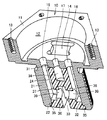
本実施形態の光学センサ1は、図19に示すように、光を発する発光素子52と、発光素子52によって発せられる光を受ける受光素子42とを備えている。発光素子52から受光素子42までの光路が、油が浸入するための空間である油浸入用空間33を通過している。光学センサ1はまた、発光素子52を搭載する基板51と、受光素子42を搭載する基板41と、基板41,51を収容する収容空間24が形成された固定部材10と、収容空間24に充填され基板41,51を封止する封止樹脂29とを備えている。固定部材10は、基板41,51を内部に収容する収容部材を構成している。
図20は、第二実施形態に基づく光学センサ1の正面図である。第二実施形態の光学センサ1では、第一実施形態とは異なり、固定部材10のネジ部21に油浸入用空間は形成されていない。第二実施形態の光学センサ1は、図20に示すように、反射部材90を備えている。反射部材90は、ネジ部21の先端面22から離隔して配置されており、先端面22と略平行に配置されている。反射部材90は、ボルト91により、ネジ部21に固定されている。
図27は、第三実施形態に基づく光学センサ1の断面図である。これまでに説明した第一および第二実施形態の光学センサ1では、断熱部材70の内部の収容空間73が中空空間であるが、図27に示すように、収容空間73内に樹脂が充填されていてもよい。第三実施形態では、基板131の一部は、封止樹脂129によって封止されている。
特開2014−8569号公報には、熱せられた潤滑油の温度と周囲の温度との温度差を電力に変換する熱発電素子が開示されている。熱発電素子の入熱面には、熱伝導部材を介して、固定部が接続されている。固定部は、潤滑油に接触して、潤滑油の熱を熱発電素子に伝導する。熱発電素子の放熱面には、放熱部材が接続されている。断熱材料製のカバーが、固定部および放熱部材に固定されて、熱発電素子を覆っている。
高温側熱伝導体と、
前記高温側熱伝導体から離隔して配置された低温側熱伝導体と、
前記高温側熱伝導体に熱的に接触する高温側電極と、前記低温側熱伝導体に熱的に接触する低温側電極とを有する、熱電発電モジュールと、
前記高温側熱伝導体と前記低温側熱伝導体との間に配置され、前記熱電発電モジュールを内部に収容する、断熱部材と、
前記断熱部材とは別部材の一体化部材とを備え、前記高温側熱伝導体と前記低温側熱伝導体とは前記一体化部材によって前記断熱部材を挟んで一体化されている、熱電発電装置。
前記一体化部材は、電気絶縁性を有する、特徴1に記載の熱電発電装置。
前記一体化部材は、前記高温側熱伝導体と前記低温側熱伝導体とを一体に締結するボルトを含む、特徴1または2に記載の熱電発電装置。
前記高温側熱伝導体と前記低温側熱伝導体とのいずれか一方または両方がボルト形状を有する、特徴1〜3のいずれか1項に記載の熱電発電装置。
前記高温側熱伝導体と前記低温側熱伝導体との間に配置された基板をさらに備える、特徴1〜4のいずれか1項に記載の熱電発電装置。
前記基板の一部または全部を封止する封止樹脂をさらに備える、特徴5に記載の熱電発電装置。
前記高温側熱伝導体と前記低温側熱伝導体との間に配置され、前記高温側熱伝導体と前記低温側熱伝導体とのいずれか一方と前記熱電発電モジュールとに接触する、熱伝導部材をさらに備える、特徴1〜6のいずれか1項に記載の熱電発電装置。
Claims (5)
- 光を発する発光素子と、
前記発光素子によって発せられる前記光を受ける受光素子であって、前記発光素子から前記受光素子までの光路が、油が浸入するための空間である油浸入用空間を通過する、受光素子と、
前記発光素子と前記受光素子とのいずれか一方または両方を搭載する基板と、
前記基板を収容する収容空間が形成された収容部材と、
前記収容空間に充填され前記基板を封止する封止樹脂とを備え、
前記発光素子と前記受光素子とは、油密性を有し、前記油浸入用空間に露出して配置される、光学センサ。 - 前記発光素子と前記受光素子とは、前記油浸入用空間を挟んで互いに向き合っている、請求項1に記載の光学センサ。
- 前記発光素子によって発せられる前記光を反射する反射部材をさらに備え、
前記受光素子は、前記反射部材によって反射された前記光を受ける、請求項1に記載の光学センサ。 - 前記発光素子と前記反射部材とは、前記油浸入用空間を挟んで互いに向き合い、
前記受光素子と前記反射部材とは、前記油浸入用空間を挟んで互いに向き合っている、請求項3に記載の光学センサ。 - 前記発光素子および前記受光素子に電力を供給する熱電発電モジュールをさらに備える、請求項1〜4のいずれか1項に記載の光学センサ。
Priority Applications (6)
| Application Number | Priority Date | Filing Date | Title |
|---|---|---|---|
| JP2016089734A JP6676459B2 (ja) | 2016-04-27 | 2016-04-27 | 光学センサ |
| PCT/JP2017/014839 WO2017187967A1 (ja) | 2016-04-27 | 2017-04-11 | 光学センサ |
| CN201780015649.2A CN108700514A (zh) | 2016-04-27 | 2017-04-11 | 光学传感器 |
| US16/092,518 US10801958B2 (en) | 2016-04-27 | 2017-04-11 | Optical sensor |
| DE112017001158.2T DE112017001158T5 (de) | 2016-04-27 | 2017-04-11 | Optischer Sensor |
| US17/014,185 US20200408685A1 (en) | 2016-04-27 | 2020-09-08 | Thermoelectric power generation apparatus |
Applications Claiming Priority (1)
| Application Number | Priority Date | Filing Date | Title |
|---|---|---|---|
| JP2016089734A JP6676459B2 (ja) | 2016-04-27 | 2016-04-27 | 光学センサ |
Related Child Applications (1)
| Application Number | Title | Priority Date | Filing Date |
|---|---|---|---|
| JP2020042030A Division JP7108651B2 (ja) | 2020-03-11 | 2020-03-11 | 熱電発電装置 |
Publications (2)
| Publication Number | Publication Date |
|---|---|
| JP2017198549A JP2017198549A (ja) | 2017-11-02 |
| JP6676459B2 true JP6676459B2 (ja) | 2020-04-08 |
Family
ID=60161654
Family Applications (1)
| Application Number | Title | Priority Date | Filing Date |
|---|---|---|---|
| JP2016089734A Active JP6676459B2 (ja) | 2016-04-27 | 2016-04-27 | 光学センサ |
Country Status (5)
| Country | Link |
|---|---|
| US (2) | US10801958B2 (ja) |
| JP (1) | JP6676459B2 (ja) |
| CN (1) | CN108700514A (ja) |
| DE (1) | DE112017001158T5 (ja) |
| WO (1) | WO2017187967A1 (ja) |
Families Citing this family (3)
| Publication number | Priority date | Publication date | Assignee | Title |
|---|---|---|---|---|
| JP7097793B2 (ja) * | 2018-10-17 | 2022-07-08 | 株式会社Kelk | 検出装置 |
| JP6954405B2 (ja) * | 2019-05-16 | 2021-10-27 | ダイキン工業株式会社 | 液体センサ及び油圧ユニット |
| WO2022189680A1 (es) * | 2021-03-08 | 2022-09-15 | Sensing Solutions S.L. | Componente para implementación de sondas ópticas y sonda óptica |
Family Cites Families (26)
| Publication number | Priority date | Publication date | Assignee | Title |
|---|---|---|---|---|
| JPS5839436A (ja) | 1981-09-03 | 1983-03-08 | Showa Gomme Kk | ゴムせん |
| JPH0731116B2 (ja) | 1986-04-10 | 1995-04-10 | 株式会社日本自動車部品総合研究所 | 油劣化検出装置 |
| JPH02118853U (ja) * | 1989-03-10 | 1990-09-25 | ||
| CN2119656U (zh) * | 1991-11-26 | 1992-10-21 | 杭州杭汇应用技术成套服务公司 | 液体透明度仪 |
| JPH06102172A (ja) * | 1992-09-17 | 1994-04-15 | Kansai Electric Power Co Inc:The | 光ファイバー水質測定器 |
| JPH07146233A (ja) | 1993-09-30 | 1995-06-06 | Shimadzu Corp | オイル劣化度センサ |
| JPH10104160A (ja) | 1996-09-30 | 1998-04-24 | Shimadzu Corp | オイル劣化度センサ |
| US6232542B1 (en) * | 1996-11-15 | 2001-05-15 | Citizen Watch Co., Ltd. | Method of fabricating thermoelectric device |
| JP2000275175A (ja) * | 1999-03-25 | 2000-10-06 | Otsuka Denshi Co Ltd | 溶液測定用光ファイバーセル |
| JP2000338041A (ja) * | 1999-03-25 | 2000-12-08 | Otsuka Denshi Co Ltd | 溶液測定用光ファイバーセル |
| JP2003168182A (ja) | 2001-12-04 | 2003-06-13 | Nsk Ltd | ワイヤレスセンサ |
| US20100157304A1 (en) * | 2006-01-23 | 2010-06-24 | Ntn Corporation | Lubricant deterioration detecting device and detecting device incorporated bearing assembly |
| JP2008026045A (ja) * | 2006-07-19 | 2008-02-07 | Ntn Corp | 潤滑剤劣化検出装置および検出装置付き軸受 |
| KR100795373B1 (ko) * | 2006-07-27 | 2008-01-17 | 한국과학기술연구원 | 오일 열화 실시간 모니터링 방법 및 장치 |
| JP2008134136A (ja) * | 2006-11-28 | 2008-06-12 | Ntn Corp | 軸受の潤滑剤劣化検出装置 |
| JP4833046B2 (ja) * | 2006-12-04 | 2011-12-07 | Ntn株式会社 | 軸受の潤滑剤劣化検出装置 |
| JP2010261808A (ja) * | 2009-05-07 | 2010-11-18 | Nippon Soken Inc | オイル性状検出装置 |
| CN201425571Y (zh) * | 2009-05-26 | 2010-03-17 | 郑州市光力科技发展有限公司 | 一种粉尘浓度测量装置 |
| JP5839436B2 (ja) | 2010-12-02 | 2016-01-06 | ナブテスコ株式会社 | 光学センサ |
| KR20130122749A (ko) | 2010-12-02 | 2013-11-08 | 나부테스코 가부시키가이샤 | 산업 로봇용 감속기 |
| GB2492821A (en) * | 2011-07-14 | 2013-01-16 | Chuan Jiing Entpr Co Ltd | Brake oil boiling point detector |
| JP5860739B2 (ja) | 2012-03-19 | 2016-02-16 | ナブテスコ株式会社 | 減速機破損状態通知装置、減速機破損状態通知機能付機械システムおよび減速機破損状態通知プログラム |
| JP5980591B2 (ja) * | 2012-06-29 | 2016-08-31 | ナブテスコ株式会社 | 色センサーおよび機械装置遠隔監視システム |
| CN103149158B (zh) * | 2013-01-14 | 2016-04-20 | 中国计量学院 | 一种双棱镜水质监测光纤传感系统 |
| JP6238338B2 (ja) * | 2013-06-28 | 2017-11-29 | ナブテスコ株式会社 | 光学式センサ及び光学式センサシステム |
| JP2016020925A (ja) * | 2015-11-04 | 2016-02-04 | ナブテスコ株式会社 | 減速機破損状態通知装置、減速機破損状態通知機能付機械システムおよび減速機破損状態通知プログラム |
-
2016
- 2016-04-27 JP JP2016089734A patent/JP6676459B2/ja active Active
-
2017
- 2017-04-11 DE DE112017001158.2T patent/DE112017001158T5/de active Pending
- 2017-04-11 US US16/092,518 patent/US10801958B2/en active Active
- 2017-04-11 CN CN201780015649.2A patent/CN108700514A/zh active Pending
- 2017-04-11 WO PCT/JP2017/014839 patent/WO2017187967A1/ja not_active Ceased
-
2020
- 2020-09-08 US US17/014,185 patent/US20200408685A1/en not_active Abandoned
Also Published As
| Publication number | Publication date |
|---|---|
| DE112017001158T5 (de) | 2018-11-22 |
| CN108700514A (zh) | 2018-10-23 |
| JP2017198549A (ja) | 2017-11-02 |
| WO2017187967A1 (ja) | 2017-11-02 |
| US20200408685A1 (en) | 2020-12-31 |
| US20190128807A1 (en) | 2019-05-02 |
| US10801958B2 (en) | 2020-10-13 |
Similar Documents
| Publication | Publication Date | Title |
|---|---|---|
| CN100575150C (zh) | 控制模块 | |
| US8075152B2 (en) | Hermetic light-emitting device | |
| US8410672B2 (en) | Thermally conductive mounting element for attachment of printed circuit board to heat sink | |
| JP4124137B2 (ja) | 電子ユニット筐体 | |
| US20080143245A1 (en) | Electroluminescent module | |
| JP6676459B2 (ja) | 光学センサ | |
| US20140179139A1 (en) | Connector for led module board | |
| KR20130067264A (ko) | 3차원 led 기판 및 led 조명 장치 | |
| US10236429B2 (en) | Mounting assembly and lighting device | |
| JP7108651B2 (ja) | 熱電発電装置 | |
| JP6412042B2 (ja) | レーザ発振器 | |
| KR102474123B1 (ko) | 방열 모듈 및 이를 포함하는 조명 장치 | |
| US10475982B2 (en) | Thermoelectric module | |
| JP2008277626A (ja) | 発光デバイス及びその製造方法 | |
| JP2006066725A (ja) | 放熱構造を備える半導体装置及びその組立方法 | |
| JP2012074148A (ja) | 発光装置及びそれを備えた照明器具 | |
| US11508892B2 (en) | Folded heatsink design for thermal challenging LED applications | |
| KR102857264B1 (ko) | 열전 발전 장치 | |
| JP6049489B2 (ja) | 光源モジュール | |
| JP6800319B2 (ja) | 電力変換装置 | |
| JP4692210B2 (ja) | 圧力センサ | |
| JP2013004824A (ja) | Led照明装置及びled照明装置の製造方法 | |
| WO2011081166A1 (ja) | デバイス設置構造及びデバイス設置方法 | |
| JP2022139130A (ja) | 電子機器 | |
| JP2015056521A (ja) | 電子装置 |
Legal Events
| Date | Code | Title | Description |
|---|---|---|---|
| A621 | Written request for application examination |
Free format text: JAPANESE INTERMEDIATE CODE: A621 Effective date: 20190304 |
|
| A131 | Notification of reasons for refusal |
Free format text: JAPANESE INTERMEDIATE CODE: A131 Effective date: 20191126 |
|
| A521 | Request for written amendment filed |
Free format text: JAPANESE INTERMEDIATE CODE: A523 Effective date: 20200117 |
|
| TRDD | Decision of grant or rejection written | ||
| A01 | Written decision to grant a patent or to grant a registration (utility model) |
Free format text: JAPANESE INTERMEDIATE CODE: A01 Effective date: 20200212 |
|
| A61 | First payment of annual fees (during grant procedure) |
Free format text: JAPANESE INTERMEDIATE CODE: A61 Effective date: 20200312 |
|
| R150 | Certificate of patent or registration of utility model |
Ref document number: 6676459 Country of ref document: JP Free format text: JAPANESE INTERMEDIATE CODE: R150 |
|
| R250 | Receipt of annual fees |
Free format text: JAPANESE INTERMEDIATE CODE: R250 |
|
| R250 | Receipt of annual fees |
Free format text: JAPANESE INTERMEDIATE CODE: R250 |
|
| R250 | Receipt of annual fees |
Free format text: JAPANESE INTERMEDIATE CODE: R250 |
|
| R250 | Receipt of annual fees |
Free format text: JAPANESE INTERMEDIATE CODE: R250 |