JP6690318B2 - ダンパ装置 - Google Patents
ダンパ装置 Download PDFInfo
- Publication number
- JP6690318B2 JP6690318B2 JP2016047875A JP2016047875A JP6690318B2 JP 6690318 B2 JP6690318 B2 JP 6690318B2 JP 2016047875 A JP2016047875 A JP 2016047875A JP 2016047875 A JP2016047875 A JP 2016047875A JP 6690318 B2 JP6690318 B2 JP 6690318B2
- Authority
- JP
- Japan
- Prior art keywords
- sheet
- elastic member
- pressing plate
- damper device
- flanged hub
- Prior art date
- Legal status (The legal status is an assumption and is not a legal conclusion. Google has not performed a legal analysis and makes no representation as to the accuracy of the status listed.)
- Active
Links
Images






Classifications
-
- F—MECHANICAL ENGINEERING; LIGHTING; HEATING; WEAPONS; BLASTING
- F16—ENGINEERING ELEMENTS AND UNITS; GENERAL MEASURES FOR PRODUCING AND MAINTAINING EFFECTIVE FUNCTIONING OF MACHINES OR INSTALLATIONS; THERMAL INSULATION IN GENERAL
- F16F—SPRINGS; SHOCK-ABSORBERS; MEANS FOR DAMPING VIBRATION
- F16F15/00—Suppression of vibrations in systems; Means or arrangements for avoiding or reducing out-of-balance forces, e.g. due to motion
- F16F15/10—Suppression of vibrations in rotating systems by making use of members moving with the system
- F16F15/12—Suppression of vibrations in rotating systems by making use of members moving with the system using elastic members or friction-damping members, e.g. between a rotating shaft and a gyratory mass mounted thereon
- F16F15/121—Suppression of vibrations in rotating systems by making use of members moving with the system using elastic members or friction-damping members, e.g. between a rotating shaft and a gyratory mass mounted thereon using springs as elastic members, e.g. metallic springs
- F16F15/123—Wound springs
- F16F15/1232—Wound springs characterised by the spring mounting
- F16F15/12326—End-caps for springs
- F16F15/12333—End-caps for springs having internal abutment means
-
- F—MECHANICAL ENGINEERING; LIGHTING; HEATING; WEAPONS; BLASTING
- F16—ENGINEERING ELEMENTS AND UNITS; GENERAL MEASURES FOR PRODUCING AND MAINTAINING EFFECTIVE FUNCTIONING OF MACHINES OR INSTALLATIONS; THERMAL INSULATION IN GENERAL
- F16D—COUPLINGS FOR TRANSMITTING ROTATION; CLUTCHES; BRAKES
- F16D13/00—Friction clutches
- F16D13/58—Details
- F16D13/60—Clutching elements
- F16D13/64—Clutch-plates; Clutch-lamellae
-
- F—MECHANICAL ENGINEERING; LIGHTING; HEATING; WEAPONS; BLASTING
- F16—ENGINEERING ELEMENTS AND UNITS; GENERAL MEASURES FOR PRODUCING AND MAINTAINING EFFECTIVE FUNCTIONING OF MACHINES OR INSTALLATIONS; THERMAL INSULATION IN GENERAL
- F16F—SPRINGS; SHOCK-ABSORBERS; MEANS FOR DAMPING VIBRATION
- F16F1/00—Springs
- F16F1/02—Springs made of steel or other material having low internal friction; Wound, torsion, leaf, cup, ring or the like springs, the material of the spring not being relevant
- F16F1/04—Wound springs
- F16F1/12—Attachments or mountings
-
- F—MECHANICAL ENGINEERING; LIGHTING; HEATING; WEAPONS; BLASTING
- F16—ENGINEERING ELEMENTS AND UNITS; GENERAL MEASURES FOR PRODUCING AND MAINTAINING EFFECTIVE FUNCTIONING OF MACHINES OR INSTALLATIONS; THERMAL INSULATION IN GENERAL
- F16F—SPRINGS; SHOCK-ABSORBERS; MEANS FOR DAMPING VIBRATION
- F16F15/00—Suppression of vibrations in systems; Means or arrangements for avoiding or reducing out-of-balance forces, e.g. due to motion
- F16F15/10—Suppression of vibrations in rotating systems by making use of members moving with the system
- F16F15/12—Suppression of vibrations in rotating systems by making use of members moving with the system using elastic members or friction-damping members, e.g. between a rotating shaft and a gyratory mass mounted thereon
- F16F15/121—Suppression of vibrations in rotating systems by making use of members moving with the system using elastic members or friction-damping members, e.g. between a rotating shaft and a gyratory mass mounted thereon using springs as elastic members, e.g. metallic springs
- F16F15/123—Wound springs
Landscapes
- Engineering & Computer Science (AREA)
- General Engineering & Computer Science (AREA)
- Mechanical Engineering (AREA)
- Physics & Mathematics (AREA)
- Acoustics & Sound (AREA)
- Aviation & Aerospace Engineering (AREA)
- Mechanical Operated Clutches (AREA)
- Springs (AREA)
Description
押圧プレートと、
前記押圧プレートに対向するように配置された回転プレートと、
前記押圧プレートと前記回転プレートとを周方向において弾性的に連結する弾性部材と、
前記弾性部材の周方向の端面に設けられたシートと、
を備え、
前記シートは、内径側において周方向に突出する凸面を有し、
前記押圧プレート及び前記回転プレートは、それぞれ、前記凸面と嵌合可能な凹面を有し、
前記シートの凸面が前記回転プレートの凹面に嵌合した状態では、前記シートの凸面と前記押圧プレートの凹面との間に隙間が形成されている。
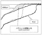
クラッチの接続時、エンジンからのトルクは、フェーシング51及び波付板バネを介してディスクプレート12に入力され、ディスクプレート12から弾性部材14を介してフランジ付きハブ11に伝達され、フランジ付きハブ11から変速機へと出力される。この時、フランジ付きハブ11とディスクプレート12とが入力されたトルク値に応じて弾性部材14を撓み収縮させながら、図10に示される捩じれ特性にて相対捩じれ回転し、これにより、ディスクプレート12からフランジ付きハブ11へのトルク伝達に緩衝作用が働く。
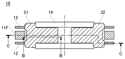
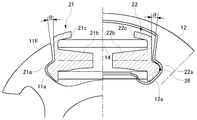
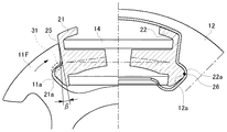
11 フランジ付きハブ(押圧プレート)
11F フランジ
12 ディスクプレート(回転プレート)
14 弾性部材
21、22 シート
21a、22a 凸部
21a1 ディスクプレートの窓のディスク周方向端面と対向する部分
22a2 フランジ付きハブの切欠きのディスク周方向端面と対向する部分
21b、22b シート弾性部材保持突起部
21c、22c シート外周保持部
25 接触部
31 隙間
51 フェーシング
52 リベット
Claims (2)
- 押圧プレートと、
前記押圧プレートに対向するように配置された回転プレートと、
前記押圧プレートと前記回転プレートとを周方向において弾性的に連結する弾性部材と、
前記弾性部材の周方向の端面に設けられたシートと、
を備え、
前記シートは、内径側において周方向に突出する凸面を有し、
前記押圧プレート及び前記回転プレートは、それぞれ、前記凸面と嵌合可能な凹面を有し、
前記シートの凸面が前記回転プレートの凹面に嵌合した状態では、前記シートの凸面と前記押圧プレートの凹面との間に隙間が形成されており、
前記シートは、外径側において前記押圧プレートと接触可能な接触部を有し、
前記押圧プレートが前記シートを押圧して前記弾性部材の撓みを開始する時点において、前記シートの凸面と前記押圧プレートの凹面との間には隙間が形成されており、
前記押圧プレートが前記シートを更に押圧する時、前記シートは前記接触部を中心に回転して前記シートの凸面が前記押圧プレートの凹面に嵌合する
ことを特徴とするダンパ装置。 - 前記押圧プレートが前記シートを押圧して前記弾性部材の撓みを開始する時点において、前記シートは前記弾性部材の外径側を押圧し、前記シートが回転して前記シートの凸面が前記押圧プレートの凹面に嵌合した後に、前記シートは前記弾性部材の中心軸を押圧する
ことを特徴とする請求項1に記載のダンパ装置。
Priority Applications (3)
| Application Number | Priority Date | Filing Date | Title |
|---|---|---|---|
| JP2016047875A JP6690318B2 (ja) | 2016-03-11 | 2016-03-11 | ダンパ装置 |
| PCT/JP2017/006283 WO2017154554A1 (ja) | 2016-03-11 | 2017-02-21 | ダンパ装置 |
| EP17762897.1A EP3428478B1 (en) | 2016-03-11 | 2017-02-21 | Damper apparatus |
Applications Claiming Priority (1)
| Application Number | Priority Date | Filing Date | Title |
|---|---|---|---|
| JP2016047875A JP6690318B2 (ja) | 2016-03-11 | 2016-03-11 | ダンパ装置 |
Publications (2)
| Publication Number | Publication Date |
|---|---|
| JP2017161036A JP2017161036A (ja) | 2017-09-14 |
| JP6690318B2 true JP6690318B2 (ja) | 2020-04-28 |
Family
ID=59790286
Family Applications (1)
| Application Number | Title | Priority Date | Filing Date |
|---|---|---|---|
| JP2016047875A Active JP6690318B2 (ja) | 2016-03-11 | 2016-03-11 | ダンパ装置 |
Country Status (3)
| Country | Link |
|---|---|
| EP (1) | EP3428478B1 (ja) |
| JP (1) | JP6690318B2 (ja) |
| WO (1) | WO2017154554A1 (ja) |
Families Citing this family (4)
| Publication number | Priority date | Publication date | Assignee | Title |
|---|---|---|---|---|
| JP7087480B2 (ja) * | 2018-03-12 | 2022-06-21 | 株式会社アイシン | ダンパ装置 |
| JP7497623B2 (ja) * | 2020-06-19 | 2024-06-11 | 株式会社アイシン | ダンパ装置 |
| JP7785522B2 (ja) * | 2021-12-07 | 2025-12-15 | 株式会社エクセディ | ダンパー装置 |
| SE2350248A1 (en) * | 2023-03-06 | 2024-01-12 | Volvo Truck Corp | Propeller shaft assembly for a motor vehicle |
Family Cites Families (7)
| Publication number | Priority date | Publication date | Assignee | Title |
|---|---|---|---|---|
| JPH01146040U (ja) * | 1988-03-31 | 1989-10-06 | ||
| JP3264294B2 (ja) * | 1993-06-24 | 2002-03-11 | 株式会社エクセディ | 捩じり振動減衰装置 |
| JP2003278792A (ja) * | 2002-03-26 | 2003-10-02 | Aisin Seiki Co Ltd | 捩じれ緩衝ディスク |
| JP4925893B2 (ja) * | 2007-03-30 | 2012-05-09 | 日産自動車株式会社 | スプリングシートおよびダンパーディスク組立体 |
| CN102667207B (zh) * | 2009-12-11 | 2014-12-10 | 丰田自动车株式会社 | 扭转缓冲装置 |
| JP5625676B2 (ja) * | 2010-09-24 | 2014-11-19 | アイシン精機株式会社 | トルク変動吸収装置 |
| JP5223999B2 (ja) * | 2011-04-01 | 2013-06-26 | トヨタ自動車株式会社 | 捩り振動減衰装置 |
-
2016
- 2016-03-11 JP JP2016047875A patent/JP6690318B2/ja active Active
-
2017
- 2017-02-21 WO PCT/JP2017/006283 patent/WO2017154554A1/ja not_active Ceased
- 2017-02-21 EP EP17762897.1A patent/EP3428478B1/en active Active
Also Published As
| Publication number | Publication date |
|---|---|
| EP3428478A1 (en) | 2019-01-16 |
| EP3428478A4 (en) | 2019-04-17 |
| JP2017161036A (ja) | 2017-09-14 |
| EP3428478B1 (en) | 2022-08-03 |
| WO2017154554A1 (ja) | 2017-09-14 |
Similar Documents
| Publication | Publication Date | Title |
|---|---|---|
| JP6756129B2 (ja) | ダンパ装置 | |
| JP6690318B2 (ja) | ダンパ装置 | |
| WO2015064237A1 (ja) | フライホイール組立体 | |
| JP6460950B2 (ja) | ダンパ装置 | |
| JP5565473B2 (ja) | 捩り振動減衰装置 | |
| JP2005106158A (ja) | トーションダンパ | |
| JP6515857B2 (ja) | ダンパ装置のスプリング保持部材 | |
| JP5817918B2 (ja) | 捩り振動減衰装置 | |
| JP7519756B2 (ja) | 自転車、及び自転車用動力伝達装置 | |
| US20220090634A1 (en) | Hysteresis torque generating mechanism and power transmission device | |
| JP7267045B2 (ja) | ダンパ装置 | |
| JP7236889B2 (ja) | ダンパ装置 | |
| JP6167839B2 (ja) | 車両用ダンパ装置 | |
| JP2021134835A (ja) | スプリングシート及びダンパ装置 | |
| US11796010B2 (en) | Torque limiter device | |
| JP4760952B2 (ja) | トーションダンパ | |
| JP6708565B2 (ja) | 動力伝達装置 | |
| JP7267046B2 (ja) | ダンパ装置 | |
| JP6043492B2 (ja) | 変速機のシャフトダンパ | |
| JP7227804B2 (ja) | ダンパ装置 | |
| JP2005282651A (ja) | 捩り振動低減装置 | |
| JP2017227222A (ja) | ダンパ装置 | |
| JP2015102219A (ja) | 車両用ダンパ装置 |
Legal Events
| Date | Code | Title | Description |
|---|---|---|---|
| A621 | Written request for application examination |
Free format text: JAPANESE INTERMEDIATE CODE: A621 Effective date: 20190208 |
|
| A131 | Notification of reasons for refusal |
Free format text: JAPANESE INTERMEDIATE CODE: A131 Effective date: 20191210 |
|
| A521 | Request for written amendment filed |
Free format text: JAPANESE INTERMEDIATE CODE: A523 Effective date: 20200123 |
|
| TRDD | Decision of grant or rejection written | ||
| A01 | Written decision to grant a patent or to grant a registration (utility model) |
Free format text: JAPANESE INTERMEDIATE CODE: A01 Effective date: 20200310 |
|
| A61 | First payment of annual fees (during grant procedure) |
Free format text: JAPANESE INTERMEDIATE CODE: A61 Effective date: 20200323 |
|
| R151 | Written notification of patent or utility model registration |
Ref document number: 6690318 Country of ref document: JP Free format text: JAPANESE INTERMEDIATE CODE: R151 |