JP6700548B2 - Seat equipment - Google Patents
Seat equipment Download PDFInfo
- Publication number
- JP6700548B2 JP6700548B2 JP2015556818A JP2015556818A JP6700548B2 JP 6700548 B2 JP6700548 B2 JP 6700548B2 JP 2015556818 A JP2015556818 A JP 2015556818A JP 2015556818 A JP2015556818 A JP 2015556818A JP 6700548 B2 JP6700548 B2 JP 6700548B2
- Authority
- JP
- Japan
- Prior art keywords
- seat
- operating body
- bottom plate
- cushion material
- cable
- Prior art date
- Legal status (The legal status is an assumption and is not a legal conclusion. Google has not performed a legal analysis and makes no representation as to the accuracy of the status listed.)
- Active
Links
Images









Classifications
-
- B—PERFORMING OPERATIONS; TRANSPORTING
- B62—LAND VEHICLES FOR TRAVELLING OTHERWISE THAN ON RAILS
- B62J—CYCLE SADDLES OR SEATS; AUXILIARY DEVICES OR ACCESSORIES SPECIALLY ADAPTED TO CYCLES AND NOT OTHERWISE PROVIDED FOR, e.g. ARTICLE CARRIERS OR CYCLE PROTECTORS
- B62J1/00—Saddles or other seats for cycles; Arrangement thereof; Component parts
- B62J1/005—Saddles having a seating area with multiple separate weight bearing surfaces
-
- B—PERFORMING OPERATIONS; TRANSPORTING
- B60—VEHICLES IN GENERAL
- B60N—SEATS SPECIALLY ADAPTED FOR VEHICLES; VEHICLE PASSENGER ACCOMMODATION NOT OTHERWISE PROVIDED FOR
- B60N2/00—Seats specially adapted for vehicles; Arrangement or mounting of seats in vehicles
- B60N2/24—Seats specially adapted for vehicles; Arrangement or mounting of seats in vehicles for particular purposes or particular vehicles
- B60N2/38—Seats specially adapted for vehicles; Arrangement or mounting of seats in vehicles for particular purposes or particular vehicles specially constructed for use on tractors or like off-road vehicles
- B60N2/40—Seats specially adapted for vehicles; Arrangement or mounting of seats in vehicles for particular purposes or particular vehicles specially constructed for use on tractors or like off-road vehicles saddle type
-
- B—PERFORMING OPERATIONS; TRANSPORTING
- B60—VEHICLES IN GENERAL
- B60N—SEATS SPECIALLY ADAPTED FOR VEHICLES; VEHICLE PASSENGER ACCOMMODATION NOT OTHERWISE PROVIDED FOR
- B60N2/00—Seats specially adapted for vehicles; Arrangement or mounting of seats in vehicles
- B60N2/62—Thigh-rests
-
- B—PERFORMING OPERATIONS; TRANSPORTING
- B62—LAND VEHICLES FOR TRAVELLING OTHERWISE THAN ON RAILS
- B62J—CYCLE SADDLES OR SEATS; AUXILIARY DEVICES OR ACCESSORIES SPECIALLY ADAPTED TO CYCLES AND NOT OTHERWISE PROVIDED FOR, e.g. ARTICLE CARRIERS OR CYCLE PROTECTORS
- B62J1/00—Saddles or other seats for cycles; Arrangement thereof; Component parts
- B62J1/007—Saddles with specific anatomical adaptations
-
- B—PERFORMING OPERATIONS; TRANSPORTING
- B62—LAND VEHICLES FOR TRAVELLING OTHERWISE THAN ON RAILS
- B62J—CYCLE SADDLES OR SEATS; AUXILIARY DEVICES OR ACCESSORIES SPECIALLY ADAPTED TO CYCLES AND NOT OTHERWISE PROVIDED FOR, e.g. ARTICLE CARRIERS OR CYCLE PROTECTORS
- B62J1/00—Saddles or other seats for cycles; Arrangement thereof; Component parts
- B62J1/10—Internal adjustment of saddles
-
- B—PERFORMING OPERATIONS; TRANSPORTING
- B62—LAND VEHICLES FOR TRAVELLING OTHERWISE THAN ON RAILS
- B62J—CYCLE SADDLES OR SEATS; AUXILIARY DEVICES OR ACCESSORIES SPECIALLY ADAPTED TO CYCLES AND NOT OTHERWISE PROVIDED FOR, e.g. ARTICLE CARRIERS OR CYCLE PROTECTORS
- B62J1/00—Saddles or other seats for cycles; Arrangement thereof; Component parts
- B62J1/12—Box-shaped seats; Bench-type seats, e.g. dual or twin seats
-
- B—PERFORMING OPERATIONS; TRANSPORTING
- B62—LAND VEHICLES FOR TRAVELLING OTHERWISE THAN ON RAILS
- B62J—CYCLE SADDLES OR SEATS; AUXILIARY DEVICES OR ACCESSORIES SPECIALLY ADAPTED TO CYCLES AND NOT OTHERWISE PROVIDED FOR, e.g. ARTICLE CARRIERS OR CYCLE PROTECTORS
- B62J45/00—Electrical equipment arrangements specially adapted for use as accessories on cycles, not otherwise provided for
- B62J45/40—Sensor arrangements; Mounting thereof
- B62J45/41—Sensor arrangements; Mounting thereof characterised by the type of sensor
- B62J45/412—Speed sensors
-
- B—PERFORMING OPERATIONS; TRANSPORTING
- B60—VEHICLES IN GENERAL
- B60N—SEATS SPECIALLY ADAPTED FOR VEHICLES; VEHICLE PASSENGER ACCOMMODATION NOT OTHERWISE PROVIDED FOR
- B60N2/00—Seats specially adapted for vehicles; Arrangement or mounting of seats in vehicles
- B60N2/02—Seats specially adapted for vehicles; Arrangement or mounting of seats in vehicles the seat or part thereof being movable, e.g. adjustable
- B60N2002/0288—Adjustable seat width
Landscapes
- Engineering & Computer Science (AREA)
- Mechanical Engineering (AREA)
- Aviation & Aerospace Engineering (AREA)
- Transportation (AREA)
- Seats For Vehicles (AREA)
Description
本発明は、乗物の乗員が着座するシートを有する座席装置に係り、特に、シートの幅方向両端部に備えた動作体の動作によってシート着座面の幅方向両端領域が回動する座席装置に関する。 The present invention relates to a seat device having a seat on which an occupant of a vehicle sits, and more particularly to a seat device in which both widthwise end regions of a seating surface are rotated by movements of operating bodies provided at both widthwise ends of the seat.
自動二輪車に搭載されたシートのように乗員が跨いで着座するシートに対しては、その性能として、走行中における座圧(体圧)の分散性が求められている。ここで、座圧の分散性とは、走行中に乗員がシートに及ぼす力の分散度合いのことであり、分散性が高いほど、乗員への負担(所謂、座り疲れ)が軽減されることとなる。 For a seat on which an occupant straddles, such as a seat mounted on a motorcycle, dispersibility of seat pressure (body pressure) during traveling is required as performance. Here, the dispersiveness of the seat pressure is the degree of dispersion of the force exerted by the occupant on the seat during traveling. The higher the dispersiveness, the less the burden on the occupant (so-called sitting fatigue). Become.
一方、上述した座圧の分散性を向上させるためには、走行時に乗員の大腿部を持ち上げて支持する等してシート着座面における乗員の臀部との接触面積を増加すればよい。走行時に乗員の大腿部を持ち上げる構成については、例えば特許文献1に開示されている構成が利用可能である。具体的に説明すると、特許文献1に開示されたシートでは、ボトムプレートと表皮材との間にエアクッションを配設し、エアクッションの内部圧力を調整することでシート着座面の形状が変更可能となっている。
On the other hand, in order to improve the dispersibility of the seat pressure described above, the contact area of the occupant's buttocks on the seat seating surface may be increased by, for example, lifting and supporting the thigh of the occupant during traveling. As a configuration for lifting the thigh of the occupant during traveling, for example, the configuration disclosed in
より詳しく説明すると、特許文献1に開示されたシートにおいて、上記のエアクッションは、シートの幅方向両端部に位置しており、エアクッションが膨出することでシート着座面の幅方向両端領域が地面から離れる向きに移動するようになっている。かかる状態では、シートに着座している乗員の大腿部が持ち上げられ、座圧が適当に分散するようになる。
More specifically, in the seat disclosed in
ところで、特許文献1のようにエアクッション等の動作体をシートの幅方向両端部に配置して当該動作体を動作させてシート着座面の形状を変化させる構成では、動作体とともにその周辺部分、具体的には動作体の上方に位置するクッション材や表皮材も追従して動くことになる。このとき、これらの部材の動きが動作体の動作に良好に追従し得ることが望ましい。その一方で、クッション材や表皮材については、形状保持の観点から一定の硬度や強度が必要となる。それ故に、通常時には形状を保持しつつ、シート着座面の形状を変更させる際にはクッション材や表皮材を動作体の動作に追従させることが求められる。しかしながら、特許文献1を含めて従来の構成では上記の要求を満たすことが困難であり、シート着座面の形状を変更させ難くなる可能性がある。
By the way, in a configuration in which an operating body such as an air cushion is arranged at both end portions in the width direction of the seat as in
また、動作体及びその付属機器(例えば、動力源としてのアクチュエータ)については、その機能を好適に発揮しつつ、着座性(座り心地)に影響が及び難い位置に配置されている必要がある。 In addition, the operating body and its accessories (for example, an actuator serving as a power source) need to be arranged at positions where the seatability (seating comfort) is not easily affected while appropriately exhibiting their functions.
そこで、本発明は、上記の問題に鑑みてなされたものであり、その目的は、シートの幅方向両端部が可動となってシート着座面の形状が変更可能となった座席装置として、シートの幅方向両端部の可動部がその内部に配置された動作体の動作によって変位し、その変位量を調整可能な装置を提供することにある。
また、本発明の他の目的は、動作体の配置によってシートの着座性に影響が及ぶのを抑制することである。Therefore, the present invention has been made in view of the above problems, and an object of the present invention is to provide a seat device in which both end portions in the width direction of the seat are movable and the shape of the seat seating surface can be changed. It is an object of the present invention to provide a device in which movable parts at both ends in the width direction are displaced by the operation of an operating body disposed inside the movable part and the amount of displacement can be adjusted.
Another object of the present invention is to prevent the seating property of the seat from being affected by the disposition of the operating body.
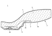
前記課題は、本発明の座席装置によれば、底板と、該底板に支持されているクッション材と、該クッション材を覆う表皮材と、を有するシートと、該シートの幅方向両端部内において、前記底板と前記クッション材との間に挟まれた状態で設けられた動作体と、を備える座席装置であって、前記幅方向両端部の各々の少なくとも一部分は、前記動作体の動作に伴って変位する可動部をなし、前記幅方向両端部の各々には、前記可動部が前記動作体の動作に伴って変位する際の連動性を向上させるための連動性向上部が前記クッション材及び前記表皮材に設けられ、前記連動性向上部は、前記動作体よりもシート幅方向外側に設けられるとともに前記クッション材の上面に形成された上端が開口する溝であって、該溝の内側は前記表皮材で被覆され、前記連動性向上部は、前記可動部と該可動部以外の非可動部との境界位置に形成されていることにより解決される。
上記の座席装置では、クッション材及び表皮材に連動性向上部としての上端が開口する溝が動作体よりもシート幅方向外側に設けられ、該溝の内側が表皮材で覆われていることで、シートの幅方向両端部に設けられた可動部は、動作体の動作に対して良好に追従し、スムーズに変位するようになる。これにより、上記の座席装置であれば、シートの着座面の形状を良好に変更することが可能となり、更に、その変更量についても容易に調整することが可能となる。
According to the seat device of the present invention, the problem is that a seat having a bottom plate, a cushion material supported by the bottom plate, and a skin material covering the cushion material, and in both widthwise end portions of the seat, A seat device comprising: an operating body provided in a state of being sandwiched between the bottom plate and the cushion material, wherein at least a part of each of the widthwise both ends is accompanied by an operation of the operating body. A movable portion that displaces is formed, and an interlocking movement improving portion for improving interlocking movement when the movable portion is displaced along with the operation of the operating body is provided at each of the both widthwise end portions. The interlocking portion provided on the skin material is a groove provided on the outer side in the seat width direction with respect to the operating body and having an upper end opened on the upper surface of the cushion material , and the inner side of the groove is This is solved by being covered with a skin material and the interlocking property improving portion is formed at a boundary position between the movable portion and the non-movable portion other than the movable portion.
In the seat device described above, the cushion material and the skin material are provided with a groove whose upper end is opened as the interlocking function improving portion on the outer side in the seat width direction with respect to the operating body , and the inside of the groove is covered with the skin material. The movable portions provided at both ends of the seat in the width direction follow the operation of the operating body satisfactorily and are smoothly displaced. Accordingly, with the seat device described above, the shape of the seating surface of the seat can be favorably changed, and the amount of change can be easily adjusted.
また、上記の座席装置において、前記動作体は、平板状の部材であり、前記溝は、前記クッション材において前記動作体の外縁に沿って形成されていると、好適である。このように、溝が動作体の外縁に沿って形成されることで、クッション材の可動部に該当する部位がより一層変形し易くなる。これにより、体圧分散性が向上することとなる。 Further, in the seat apparatus described above, it is preferable that the operating body is a flat plate-shaped member and the groove is formed along the outer edge of the operating body in the cushion material. In this way, by forming the groove along the outer edge of the operating body, the portion of the cushion material corresponding to the movable portion is more easily deformed. Thereby, the body pressure dispersibility is improved.
また、上記の座席装置において、前記動作体に動力を付与する動力源を更に備え、該動力源は、前記底板と前記クッション材との間に挟まれた状態で、前記連動性向上部から離間した位置に配置されていると、より好適である。かかる構成であれば、シート内の機器レイアウトに影響を与えるのを抑えつつ、動力源を配置することが可能となる。特に、連動性向上部から離間した位置に動力源を配置することで、動力源がクッション材の変形を阻害してしまうのを抑制することが可能となる。 Further, the seat device described above further includes a power source for applying power to the operating body, and the power source is separated from the interlocking property improving portion in a state of being sandwiched between the bottom plate and the cushion material. It is more preferable to be arranged in the position. With such a configuration, it becomes possible to arrange the power source while suppressing the influence on the device layout in the seat. In particular, by disposing the power source at a position separated from the interlocking property improving portion, it is possible to prevent the power source from inhibiting the deformation of the cushion material.
また、上記の座席装置において、前記動力源からの動力を前記動作体に伝達するためのケーブルが、前記底板において前記クッション材を支持する支持面に沿って敷設されていると、より一層好適である。かかる構成であれば、底板のクッション材支持面に沿ってケーブルを敷設するので、ケーブルがシートの着座性に影響を及ぼすのを抑制することが可能である。 Further, in the seat apparatus described above, it is even more preferable that a cable for transmitting power from the power source to the operating body is laid along a support surface that supports the cushion material in the bottom plate. is there. With such a configuration, since the cable is laid along the cushion material supporting surface of the bottom plate, it is possible to suppress the cable from affecting the seating property of the seat.
前記課題は、本発明の座席装置によれば、底板と、該底板に支持されているクッション材と、該クッション材を覆う表皮材と、を有するシートと、該シートの幅方向両端部内において、前記底板と前記クッション材との間に挟まれた状態で設けられた動作体と、前記動作体に動力を付与する動力源と、を備える座席装置であって、前記幅方向両端部の各々の少なくとも一部分は、前記動作体の動作に伴って変位する可動部をなし、前記幅方向両端部の各々では、前記可動部が前記動作体の動作に伴って変位する際の連動性を向上させるための連動性向上部が前記クッション材及び前記表皮材のうちの少なくとも一方に設けられて前記可動部と該可動部以外の部分との境界を形成し、前記動力源は、前記底板と前記クッション材との間に挟まれた状態で、前記連動性向上部から離間した位置に配置されており、前記動力源からの動力を前記動作体に伝達するためのケーブルが、前記底板において前記クッション材を支持する支持面に沿って敷設されており、前記動作体は、平板状の部材であり、前記ケーブルは、前記動力源であるアクチュエータによって牽引され、前記動作体と前記底板との間に配置され、前記動作体と当接する当接部材を更に備え、前記ケーブルの牽引に伴って、該ケーブルが係止された前記当接部材の一端部が前記当接部材の他端部に向かって移動することで、前記当接部材のうち、前記一端部及び前記他端部の間に位置する中間部が前記動作体を押圧する向きに屈曲し、前記底板には、前記幅方向において前記当接部材を挟み込む位置に凸状のガイド部が前記一端部の移動方向に沿って設けられていることにより解決される。
上記の構成では、ケーブルがアクチュエータに牽引されると、当接部材の一端部が他端部に向かって移動する。この結果、当接部材の中間部が屈曲して動作体を押圧し、押圧を受けた動作体がシートの可動部を回動させるようになる。この際、当接部材の一端部は、底板に設けられたガイド部にガイドされながら移動するので、当接部材の他端部に向かって適切に移動するようになる。また、凸状のガイド部を設けることで底板の剛性、特に、動作体が配置されている付近の領域の剛性を高めることが可能となる。
According to the seat device of the present invention, the problem is that a seat having a bottom plate, a cushion material supported by the bottom plate, and a skin material covering the cushion material, and in both widthwise end portions of the seat, A seat device including an operating body provided in a state of being sandwiched between the bottom plate and the cushioning material, and a power source for applying power to the operating body, wherein each of the widthwise both end portions is provided. At least a part of the movable body is a movable portion that is displaced in accordance with the movement of the operating body, and at each of the widthwise both ends, in order to improve the interlocking property when the movable portion is displaced in accordance with the movement of the operating body. Is provided on at least one of the cushion material and the skin material to form a boundary between the movable portion and a portion other than the movable portion, and the power source is the bottom plate and the cushion material. A cable for transmitting power from the power source to the operating body, which is arranged at a position separated from the interlocking property improving portion in a state of being sandwiched between the cushion member and the cushion member in the bottom plate. It is laid along a supporting surface for supporting, the operating body is a flat plate-shaped member, the cable is pulled by an actuator which is the power source, and is arranged between the operating body and the bottom plate. A contact member that contacts the operating body is provided, and one end of the contact member with which the cable is locked moves toward the other end of the contact member when the cable is pulled. Thus, of the contact members, an intermediate portion located between the one end portion and the other end portion bends in a direction of pressing the operating body, and the bottom plate has the contact member in the width direction. This is solved by providing a convex guide portion at a position sandwiching the end portion along the moving direction of the one end portion .
In the above configuration, when the cable is pulled by the actuator, one end of the contact member moves toward the other end. As a result, the intermediate portion of the contact member bends to press the operating body, and the operating body that receives the press rotates the movable portion of the seat. At this time, since one end of the contact member moves while being guided by the guide portion provided on the bottom plate, it appropriately moves toward the other end of the contact member. Further, by providing the convex guide portion, it becomes possible to increase the rigidity of the bottom plate, particularly, the rigidity of the region in the vicinity where the operating body is arranged.
前記課題は、本発明の座席装置によれば、底板と、該底板に支持されているクッション材と、該クッション材を覆う表皮材と、を有するシートと、該シートの幅方向両端部内において、前記底板と前記クッション材との間に挟まれた状態で設けられた動作体と、前記動作体に動力を付与する動力源と、を備える座席装置であって、前記幅方向両端部の各々の少なくとも一部分は、前記動作体の動作に伴って変位する可動部をなし、前記幅方向両端部の各々では、前記可動部が前記動作体の動作に伴って変位する際の連動性を向上させるための連動性向上部が前記クッション材及び前記表皮材のうちの少なくとも一方に設けられて前記可動部と該可動部以外の部分との境界を形成し、前記動力源は、前記底板と前記クッション材との間に挟まれた状態で、前記連動性向上部から離間した位置に配置されており、前記シートは、前端部及び後端部にそれぞれ乗物の乗員が着座することが可能な二人乗り用のシートであり、前記動力源は、前記シートの前後方向において前記前端部及び前記後端部のそれぞれの着座位置の間に配置されていることにより解決される。
かかる構成であれば、乗員の着座位置の間、すなわち、乗員が着座しない位置に動力源が配置されるので、動力源がシートの着座性に影響を及ぼすのを抑制することが可能である。
According to the seat device of the present invention, the problem is that a seat having a bottom plate, a cushion material supported by the bottom plate, and a skin material covering the cushion material, and in both widthwise end portions of the seat, A seat device including an operating body provided in a state of being sandwiched between the bottom plate and the cushioning material, and a power source for applying power to the operating body, wherein each of the widthwise both end portions is provided. At least a part of the movable body is a movable portion that is displaced in accordance with the movement of the operating body, and at each of both widthwise end portions, in order to improve interlocking property when the movable portion is displaced in accordance with the movement of the operating body. Is provided on at least one of the cushion material and the skin material to form a boundary between the movable portion and a portion other than the movable portion, and the power source is the bottom plate and the cushion material. The seat is disposed at a position separated from the interlocking property improving part in a state of being sandwiched between the seat and the seat, and the seat is a two-seater capable of seating a vehicle occupant at the front end and the rear end, respectively. And a power source disposed between seating positions of the front end portion and the rear end portion in the front-rear direction of the seat .
With such a configuration, since the power source is arranged between the seated positions of the occupant, that is, at a position where the occupant does not sit, it is possible to suppress the power source from affecting the seatability of the seat.
また、上記の座席装置において、前記動力源は、前記幅方向において前記シートの中央部に配置されていると、尚一層好適である。かかる構成では、動力源をシート内により容易に配置することが可能である。つまり、二人乗り用のシートにおいて着座位置の間に位置する部分では、幅方向端部におけるスペースよりも幅方向中央部におけるスペースの方が広く、動力源を配置させ易い。このため、乗員の着座位置の間に動力源を配置する際、シートの幅方向中央部に配置すれば、より容易に動力源を配置することが可能となる。 Further, in the seat apparatus described above, it is even more preferable that the power source is arranged in a central portion of the seat in the width direction. With such a configuration, the power source can be arranged in the seat more easily. That is, in the portion of the seat for two passengers located between the sitting positions, the space in the widthwise central portion is larger than the space in the widthwise end portions, and the power source can be easily arranged. Therefore, when the power source is arranged between the seated positions of the occupant, if the power source is arranged at the center portion in the width direction of the seat, the power source can be arranged more easily.
前記課題は、本発明の座席装置によれば、底板と、該底板に支持されているクッション材と、該クッション材を覆う表皮材と、を有するシートと、該シートの幅方向両端部内において、前記底板と前記クッション材との間に挟まれた状態で設けられた動作体と、前記動作体に動力を付与する動力源と、該動力源からの動力を前記動作体に伝達するために動く動力伝達体と、を備える座席装置であって、前記幅方向両端部の各々の少なくとも一部分は、前記動作体の動作に伴って変位する可動部をなし、前記幅方向両端部の各々では、前記可動部が前記動作体の動作に伴って変位する際の連動性を向上させるための連動性向上部が前記クッション材及び前記表皮材のうちの少なくとも一方に設けられて前記可動部と該可動部以外の部分との境界を形成し、前記シートは、前記表皮材に一端が接合されており張られることで前記表皮材に張力を付与する張力付与部材を有し、該張力付与部材の他端は、前記動力伝達体に固定されており、前記可動部が前記シートに着座する乗員に向かって変位するように前記動作体が動作する際、前記動力伝達体が前記他端と一体的に動くことで、前記張力付与部材の状態が張られた状態から弛んだ状態に移行することにより解決される。
かかる構成では、可動部がシートに着座する乗員に向かって変位するように動作体が動作する際、動力伝達体が張力付与部の他端と一体的に動くことで、張力付与部材の状態が張られた状態から弛んだ状態に移行する。これにより、表皮材が動作体の動作に追従し易くなる。そして、可動部が所定位置まで変位するまで表皮材が動くと、張力付与部材の状態は再び張られた状態に復元し、これにより、表皮材は、再び張力を付与されることで良好な外観を呈するようになる。
According to the seat device of the present invention, the problem is that a seat having a bottom plate, a cushion material supported by the bottom plate, and a skin material covering the cushion material, and in both widthwise end portions of the seat, An operating body provided in a state of being sandwiched between the bottom plate and the cushion material, a power source for giving power to the operating body, and a power source for moving the power from the power source to the operating body. A power transmission body , wherein at least a part of each of the width direction both ends forms a movable portion that is displaced in accordance with the operation of the operation body, and in each of the width direction both ends, At least one of the cushion material and the skin material is provided with an interlocking movement improving portion for improving interlocking movement when the movable portion is displaced in accordance with the movement of the operating body. forming a boundary between the portion other than the sheet has a tension applying member that applies tension to the skin material by one end to said skin material is spanned are joined, the other the tension applying member The end is fixed to the power transmission body, and when the operation body operates so that the movable portion is displaced toward the occupant seated on the seat, the power transmission body is integrally formed with the other end. This is solved by moving the tension applying member from a tensioned state to a loosened state by moving .
In such a configuration, when the operating body operates such that the movable portion is displaced toward the occupant seated on the seat, the power transmission body moves integrally with the other end of the tension applying portion, so that the state of the tension applying member is changed. Transition from a stretched state to a loose state. This makes it easier for the skin material to follow the motion of the motion body. Then, when the skin material moves until the movable portion is displaced to the predetermined position, the state of the tension applying member is restored to the stretched state, whereby the skin material is re-tensioned and has a good appearance. Comes to present.
前記課題は、本発明の座席装置によれば、底板と、該底板に支持されているクッション材と、該クッション材を覆う表皮材と、を有するシートと、該シートの幅方向両端部内において、前記底板と前記クッション材との間に挟まれた状態で設けられた動作体と、前記動作体に動力を付与する動力源と、を備える座席装置であって、前記幅方向両端部の各々の少なくとも一部分は、前記動作体の動作に伴って変位する可動部をなし、前記幅方向両端部の各々では、前記可動部が前記動作体の動作に伴って変位する際の連動性を向上させるための連動性向上部が前記クッション材及び前記表皮材のうちの少なくとも一方に設けられて前記可動部と該可動部以外の部分との境界を形成し、前記動力源は、前記底板と前記クッション材との間に挟まれた状態で、前記連動性向上部から離間した位置に配置されており、前記動力源からの動力を前記動作体に伝達するためのケーブルが、前記底板において前記クッション材を支持する支持面に沿って敷設されており、前記動作体は、平板状の部材であり、前記ケーブルは、前記動力源であるアクチュエータによって牽引され、前記底板に形成された窪み状の収容部内において回動可能な状態で収容され、前記動作体と当接する当接部材を更に備え、前記ケーブルの牽引に伴って、前記当接部材の一部分が前記収容部の外へ突き出る位置まで前記当接部材が回動し、前記動作体が、突き出た前記当接部材の前記一部分によって押圧されることで前記可動部を変位させるように動作することにより解決される。
上記の構成では、底板に形成された窪み状の収容部内に当接部材を収容し、動作体を動作させるときにのみ当接部材の一部が収容部の外に突き出る。これにより、当接部材の配置スペースを省スペース化することが可能となり、シートのレイアウトを好適に設計することが可能となる。
According to the seat device of the present invention, the problem is that a seat having a bottom plate, a cushion material supported by the bottom plate, and a skin material covering the cushion material, and in both widthwise end portions of the seat, A seat device including an operating body provided in a state of being sandwiched between the bottom plate and the cushioning material, and a power source for applying power to the operating body, wherein each of the widthwise both end portions is provided. At least a part of the movable body is a movable portion that is displaced in accordance with the movement of the operating body, and at each of the widthwise both ends, in order to improve the interlocking property when the movable portion is displaced in accordance with the movement of the operating body. Is provided on at least one of the cushion material and the skin material to form a boundary between the movable portion and a portion other than the movable portion, and the power source is the bottom plate and the cushion material. A cable for transmitting power from the power source to the operating body, which is arranged at a position separated from the interlocking property improving portion in a state of being sandwiched between the cushion member and the cushion member in the bottom plate. It is laid along a supporting surface for supporting, the operating body is a flat plate-shaped member, the cable is pulled by an actuator that is the power source, and in a hollow-shaped accommodating portion formed in the bottom plate. The contact member is further housed in a rotatable state and abuts against the operating body, and the contact member reaches a position where a part of the contact member protrudes outside the accommodating portion as the cable is pulled. Is rotated, and the operating body operates by displacing the movable part by being pressed by the part of the protruding contact member .
In the above configuration, the contact member is housed in the recessed accommodating portion formed on the bottom plate, and a part of the contact member projects out of the accommodating portion only when the operating body is operated. As a result, the space for disposing the contact member can be saved, and the layout of the seat can be designed appropriately.
また、上記の座席装置において、前記動作体において前記当接部材と対向する側の面には、格子状に形成された補強リブが設けられていると、好適である。かかる構成では、格子状の補強リブが設けられていることにより、動作体の剛性を確保しつつ、動作体を軽量化することが可能となる。 Further, in the seat apparatus described above, it is preferable that a reinforcing rib formed in a lattice shape is provided on a surface of the operating body facing the contact member. In this configuration, since the grid-shaped reinforcing ribs are provided, it is possible to reduce the weight of the operating body while ensuring the rigidity of the operating body.
また、上記の座席装置において、前記動作体において前記当接部材と対向する側の面のうち、前記当接部材が当接する領域は、前記当接部材に向かって凸状に突出していると、より好適である。かかる構成では、動作体において当接部材と対向する側の面のうち、当接部材との当接領域が凸状に突出しているので、当該領域付近の剛性をより高めることが可能となる。 Further, in the seat device described above, in the surface of the operating body facing the contact member, a region contacted by the contact member projects in a convex shape toward the contact member, It is more suitable. With such a configuration, of the surface of the operating body on the side facing the contact member, the contact area with the contact member projects in a convex shape, so that the rigidity in the vicinity of the area can be further increased.
また、上記の座席装置において、前記当接部材の外表面には、格子状に形成された補強リブが設けられていると、尚好適である。かかる構成では、格子状の補強リブが設けられていることにより、当接部材の剛性を確保しつつ、当接部材を軽量化することが可能となる。 Further, in the seat device described above, it is more preferable that the outer surface of the contact member is provided with a reinforcing rib formed in a lattice shape. In this configuration, since the grid-like reinforcing ribs are provided, it is possible to reduce the weight of the contact member while ensuring the rigidity of the contact member.
前記課題は、本発明の座席装置によれば、底板と、該底板に支持されているクッション材と、該クッション材を覆う表皮材と、を有するシートと、該シートの幅方向両端部内において、前記底板と前記クッション材との間に挟まれた状態で設けられた動作体と、前記動作体に動力を付与する動力源と、を備える座席装置であって、前記幅方向両端部の各々の少なくとも一部分は、前記動作体の動作に伴って変位する可動部をなし、前記幅方向両端部の各々では、前記可動部が前記動作体の動作に伴って変位する際の連動性を向上させるための連動性向上部が前記クッション材及び前記表皮材のうちの少なくとも一方に設けられて前記可動部と該可動部以外の部分との境界を形成し、前記動力源は、前記底板と前記クッション材との間に挟まれた状態で、前記連動性向上部から離間した位置に配置されており、前記動力源からの動力を前記動作体に伝達するためのケーブルが、前記底板において前記クッション材を支持する支持面に沿って敷設されており、前記底板には、前記ケーブルを前記支持面に沿って敷設するために形成されたケーブル収容溝が形成されており、該ケーブル収容溝の内壁には、前記ケーブル収容溝内に収容された前記ケーブルと当接して該ケーブルの位置を固定するための凸部が形成されていることにより解決される。
上記の構成では、ケーブル収容溝内でケーブルが凸部に当接することで当該ケーブルの位置が固定されるようになる。これにより、ケーブル敷設をよりスムーズに行うことが可能となるため、シートの組立作業の作業効率が向上する。
According to the seat device of the present invention, the problem is that a seat having a bottom plate, a cushion material supported by the bottom plate, and a skin material covering the cushion material, and in both widthwise end portions of the seat, A seat device including an operating body provided in a state of being sandwiched between the bottom plate and the cushioning material, and a power source for applying power to the operating body, wherein each of the widthwise both end portions is provided. At least a part of the movable body is a movable portion that is displaced in accordance with the movement of the operating body, and at each of the widthwise both ends, in order to improve the interlocking property when the movable portion is displaced in accordance with the movement of the operating body. Is provided on at least one of the cushion material and the skin material to form a boundary between the movable portion and a portion other than the movable portion, and the power source is the bottom plate and the cushion material. A cable for transmitting power from the power source to the operating body, which is disposed at a position separated from the interlocking property improving portion in a state of being sandwiched between the cushion member and the cushion member in the bottom plate. It is laid along a supporting surface for supporting, and the bottom plate has a cable housing groove formed for laying the cable along the supporting surface, and an inner wall of the cable housing groove is formed. The problem is solved by forming a convex portion for contacting the cable accommodated in the cable accommodation groove and fixing the position of the cable .
In the above configuration, the position of the cable is fixed by the cable coming into contact with the convex portion in the cable housing groove. As a result, the cable can be laid more smoothly, so that the work efficiency of the seat assembling work is improved.
また、上記の座席装置において、前記シートは、乗物の乗員が着座するシートであり、前記動作体は、前記幅方向において前記動作体の一端側に設けられた回動軸を中心として回動し、前記幅方向において、前記シートに着座した状態にある前記乗員の坐骨が存する範囲から外れた位置に、前記動作体及び前記回動軸が配置されていると、より一層好適である。
一般的に、乗員の坐骨が存在する範囲ではシートの着座面に掛かる圧力(座圧)が高くなるが、上記の構成では、動作体及びその回動軸が幅方向において、シートに着座している乗員の坐骨が存する範囲から外れた位置に配置されている。これにより、動作体は、乗員に違和感を与えることなく適切に動作するようになる。また、動作体が、幅方向において乗員の坐骨が存する範囲から外れた位置にて動作することにより、坐骨付近での座圧を分散させることが可能となる。この結果、坐骨付近での座圧が高まることで乗員の臀部に掛かる負荷が軽減されるようになる。Further, in the seat apparatus described above, the seat is a seat on which an occupant of a vehicle is seated, and the operating body rotates about a rotating shaft provided at one end side of the operating body in the width direction. It is even more preferable that, in the width direction, the operating body and the rotating shaft are arranged at positions outside the range where the occupant's ischial seated on the seat is present.
Generally, the pressure (seat pressure) applied to the seating surface of the seat is high in the range where the occupant's ischium exists, but with the above configuration, the operating body and its rotation axis are seated on the seat in the width direction. It is located outside the area where the occupant's ischium exists. As a result, the operating body can properly operate without giving an occupant a feeling of strangeness. Further, the operating body operates in a position outside the range in which the occupant's ischium exists in the width direction, so that the seat pressure near the ischium can be dispersed. As a result, the seat pressure near the ischial bone is increased, and the load on the buttocks of the occupant is reduced.
また、上記の座席装置において、前記動力源からの動力を前記幅方向の一端部に設けられた前記動作体に伝達するための前記ケーブルと、前記動力源からの動力を前記幅方向の他端部に設けられた前記動作体に伝達するための前記ケーブルと、が別々に設けられ、それぞれの前記動作体には、前記動作体別に設けられた前記ケーブルのうち、対応する一方の前記ケーブルのみを通じて前記動力源からの動力が伝達されると、尚更好適である。
上記の構成では、2つのケーブルのそれぞれが互いに独立した状態で敷設されており、各動作体は、2つのケーブルのうち、対応する一方のケーブルのみを通じて動力源からの動力を受けることになる。これにより、各ケーブルを、その敷設経路の中途位置での曲げを比較的少なくした上で敷設することが可能である。これにより、ケーブル牽引時のロス(牽引ロス)が抑えられ、動作体への動力伝達が適切に行われるようになる。Further, in the above seat apparatus, the cable for transmitting the power from the power source to the operating body provided at one end in the width direction, and the other power in the width direction from the power source. And a cable for transmitting to the operating body provided in a part, and each operating body has only one corresponding cable among the cables provided for each operating body. It is even more preferable that the power from the power source is transmitted through the.
In the above configuration, the two cables are laid independently of each other, and each operating body receives the power from the power source through only one corresponding cable of the two cables. As a result, it is possible to lay each cable with relatively little bending at the midway position of the laying route. As a result, loss during cable pulling (pulling loss) is suppressed, and power is properly transmitted to the operating body.
また、上記の座席装置において、前記シートは、乗物の乗員が着座するシートであり、前記乗物の走行速度を検知するセンサと、前記動作体を制御する制御機構と、該制御機構の制御の有無を切り替えるためにオンオフするスイッチと、を備え、該スイッチがオンとなっているときに、前記制御機構は、前記センサの検知結果に応じた前記動作体を制御することとしてもよい。
上記の構成では、スイッチがオンとなっているときに乗物の走行速度に応じて動作体を動作させ、シートの着座面の形状を変更する。これにより、例えば、乗物が停止しているときや乗員が乗物から降りるときには、動作体を動作させないことにより、シートに着座している乗員の足が地面に付き易くなる。その一方で、乗物が比較的早い速度にて走行している場合には、動作体を動作させてシートの着座面の形状を変更させることで、乗員の大腿部が持ち上げられ、座圧が適当に分散するようになる。また、スイッチがオンとなっているときに限り動作体が動作するので、その時点でのモードが、着座面の形状を変更するモード/変更させないモードのいずれであるのかを確認することが可能となる。Further, in the above seat apparatus, the seat is a seat on which an occupant of a vehicle is seated, a sensor for detecting a traveling speed of the vehicle, a control mechanism for controlling the operating body, and whether or not the control mechanism is controlled. And a switch that is turned on and off for switching the switch, and when the switch is on, the control mechanism may control the operating body according to the detection result of the sensor.
In the above configuration, when the switch is turned on, the operating body is operated according to the traveling speed of the vehicle to change the shape of the seating surface of the seat. Accordingly, for example, when the vehicle is stopped or the occupant is getting off the vehicle, the foot of the occupant sitting on the seat is easily attached to the ground by not operating the operating body. On the other hand, when the vehicle is traveling at a relatively high speed, by moving the operating body to change the shape of the seating surface of the seat, the thigh of the occupant is lifted and the seat pressure is increased. It will be dispersed appropriately. Also, since the operating body operates only when the switch is on, it is possible to confirm whether the mode at that time is a mode in which the shape of the seating surface is changed or a mode in which it is not changed. Become.
また、上記の座席装置において、前記動作体を制御する制御機構と、前記動作体の動作量を調整するために操作される動作量調整用スイッチと、を備え、前記制御機構は、前記動作量調整用スイッチの操作を通じて調整された前記動作量だけ動作するように前記動作体を制御することとしてもよい。
上記の構成では、動作体の動作量が、動作量調整用スイッチの操作を通じて自在に調整可能である。このため、ユーザは、動作体を動作させてシートの着座面の形状を変更させる際に、好みの形状となるように動作体の動作量を調整することが可能となる。In the above seat device, a control mechanism for controlling the operating body and an operation amount adjusting switch operated to adjust the operating amount of the operating body are provided, and the control mechanism is configured to operate the operating amount. The operation body may be controlled to operate by the operation amount adjusted by operating the adjustment switch.
In the above configuration, the operation amount of the operation body can be freely adjusted by operating the operation amount adjustment switch. Therefore, when the user operates the operating body to change the shape of the seating surface of the seat, the user can adjust the operation amount of the operating body so as to obtain a desired shape.
また、上記の座席装置において、前記底板は、前記幅方向において前記当接部材よりも外側に位置する部分に、前記表皮材と同じ側にある面が平坦面となった平坦部を備えていると、より好適である。
上記の構成では、底板のうち、幅方向において当接部材よりも外側に位置する部分に平坦部が設けられ、かかる平坦部の、表皮材と同じ側にある面が平坦面となっている。かかる構成であれば、平坦部の上にスペースが確保されるようになり、例えば表皮材を吊り込む際に当該スペースを利用すれば、より効率よく作業を行うことが可能となる。Further, in the above-described seat device, the bottom plate includes a flat portion in which a surface on the same side as the skin material is a flat surface, in a portion located outside the contact member in the width direction. Is more preferable.
In the above configuration, a flat portion is provided on a portion of the bottom plate that is located outside the abutting member in the width direction, and a surface of the flat portion on the same side as the skin material is a flat surface. With such a configuration, a space is secured on the flat portion, and if the space is used when suspending the skin material, for example, the work can be performed more efficiently.
また、上記の座席装置において、前記動作体は、前記幅方向において前記動作体の一端側に設けられた回動軸を中心として回動し、前記幅方向において前記回動軸を跨いだ状態で前記動作体の一端部を前記底板に向かって押圧する押圧部材を備えると、さらに好適である。
上記の構成では、動作体を押圧部材によって押さえておく。これにより、動作体が動作していない間には動作体のバタツキを抑えることが可能となり、結果として、シートの着座面の形状やシートの外観が良好に保持されるようになる。Further, in the seat apparatus described above, the operating body rotates about a rotation axis provided at one end side of the operating body in the width direction, and in a state of straddling the rotation axis in the width direction. It is more preferable to include a pressing member that presses one end of the operating body toward the bottom plate.
In the above configuration, the operating body is held by the pressing member. This makes it possible to suppress the fluttering of the operating body while the operating body is not operating, and as a result, the shape of the seating surface of the seat and the appearance of the seat are favorably maintained.
また、上記の座席装置において、前記クッション材には、前記表皮材を吊り込むための第二の溝が形成されており、該第二の溝は、前記クッション材の厚み方向において前記動作体が存する範囲に達し、かつ、前記幅方向において前記動作体の脇位置を通るように形成されていることとしてもよい。
上記の構成では、表皮材を吊り込むためにクッション材に形成された第二の溝が、クッション材の厚み方向において動作体が存する範囲に達し、かつ、幅方向において動作体の脇位置を通るように形成されている。かかる構成によれば、上記の第二の溝によって表皮材を適切に吊り込むと共に、同じく上記の第二の溝によって動作体がスムーズに動作するようになる。
Further, in the above seat device, in the cushion member, the have the second groove for Komu hanging skin material is formed, said second groove, said operation member in the thickness direction of the cushion material It may be formed so as to reach an existing range and pass through the side position of the operating body in the width direction.
In the above configuration, the second groove formed in the cushion material for suspending the skin material reaches the range in which the operating body exists in the thickness direction of the cushion material, and passes the side position of the operating body in the width direction. Is formed. According to such a configuration, the above-mentioned second groove with Komu hanging suitably skin material, also becomes the operable by said second groove to operate smoothly.
また、上記の座席装置において、前記表皮材の端末部は、前記動作体に固定されており、前記動作体と一体的に動作することとしてもよい。
上記の構成では、表皮材の端末部が動作体に固定されており、動作体が動作する際には表皮材の端末部と動作体とが一体的に動作することになる。かかる構成によれば、動作体の動きに伴って表皮材に弛みが発生するのを抑えることが可能となり、この結果、シートの外観が良好に保持されるようになる。Further, in the seat device described above, the end portion of the skin material may be fixed to the operating body and may operate integrally with the operating body.
In the above configuration, the terminal portion of the skin material is fixed to the operating body, and when the operating body operates, the terminal portion of the skin material and the operating body operate integrally. With such a configuration, it is possible to suppress the occurrence of slack in the skin material due to the movement of the operating body, and as a result, the appearance of the seat is favorably maintained.
本発明によれば、シートの幅方向両端部に設けられた可動部が動作体の動作に対して良好に追従し、スムーズに変位する結果、シートの着座面の形状を良好に変更し、その変更量についても容易に調整することが可能となる。
また、本発明によれば、クッション材に連動性向上部としての切り込みが形成されることで、クッション材のうち、可動部に該当する部位が動作体の動作に良好に追従するようになる。さらに、切り込みが動作体の外縁に沿って形成されることで、クッション材の可動部に該当する部位がより一層変形し易くなり、体圧分散性が向上することとなる。
また、本発明によれば、切り込みから離間した位置に動力源を配置することで、動力源がクッション材の変形を阻害してしまうのを抑制することが可能となる。
また、本発明によれば、底板のクッション材支持面に沿ってケーブルを敷設するので、ケーブルがシートの着座性に影響を及ぼすのを抑制することが可能である。
また、本発明によれば、当接部材の一端部が底板に設けられたガイド部にガイドされながら当接部材の他端部に向かって適切に移動するようになる。また、凸状のガイド部を設けることで底板中、動作体が配置されている付近の領域の剛性が向上する。
また、本発明によれば、乗員の着座位置の間に動力源を配置することで、動力源がシートの着座性に影響を及ぼすのを抑制することが可能となる。
また、本発明によれば、動力源をシート内により容易に配置することが可能となる。
また、本発明によれば、可動部がシートに着座する乗員に向かって変位するように動作体が動作する際、張力付与部材が弛むことで、表皮材は動作体の動作に追従し易くなる。そして、可動部が所定位置まで回動するまで表皮材が動くと、張力付与部材が再び張られるようになり、表皮材は再び張力を付与されることで良好な外観を呈するようになる。
また、本発明によれば、当接部材の配置スペースを省スペース化することが可能となり、シートのレイアウトを好適に設計することが可能となる。
また、本発明によれば、当接部材の剛性を確保しつつ、当該当接部材を軽量化することが可能となる。
また、本発明によれば、動作体において当接部材と対向する側の面のうち、当接部材との当接領域付近の剛性をより高めることが可能となる。
また、本発明によれば、当接部材の剛性を確保しつつ、当接部材を軽量化することが可能となる。
また、本発明によれば、ケーブル敷設をよりスムーズに行うことが可能となるため、シートの組立作業の作業効率が向上する。
また、本発明によれば、動作体は、乗員に違和感を与えることなく適切に動作するようになる。また、坐骨付近での座圧を分散させることが可能となるので、坐骨付近での座圧が高まることで乗員の臀部に掛かる負荷を、軽減することが可能となる。
また、本発明によれば、ケーブル牽引時のロス(牽引ロス)が抑えられ、動作体への動力伝達が適切に行われるようになる。
また、本発明によれば、乗物が停止しているときや乗員が乗物から降りるときには、シートに着座している乗員の足が地面に付き易くなる。その一方で、乗物が比較的早い速度にて走行している場合には、乗員の大腿部が持ち上げられて座圧が適当に分散するようになる。また、その時点でのモードが、着座面の形状を変更するモード/変更させないモードのいずれであるのかを確認することが可能となる。
また、本発明によれば、ユーザは、動作体を動作させてシートの着座面の形状を変更させる際に、好みの形状となるように動作体の動作量を調整することが可能となる。
また、本発明によれば、例えば表皮材を吊り込む際により効率よく作業を行うことが可能となる。
また、本発明によれば、動作体が動作していない間に動作体のバタツキを抑え、シートの着座面の形状やシートの外観を良好に保持することが可能となる。
また、本発明によれば、表皮材を吊り込むためにクッション材に形成された溝によって表皮材を適切に吊り込むと共に、動作体をスムーズに動作させることが可能となる。
また、本発明によれば、動作体の動きに伴って表皮材に弛みが発生するのを抑え、シートの外観を良好に保持することが可能となる。According to the present invention, the movable portions provided at both ends in the width direction of the seat satisfactorily follow the operation of the operating body and are smoothly displaced. It is possible to easily adjust the change amount.
Further, according to the present invention, the notch as the interlocking movement improving portion is formed in the cushion material, so that the portion of the cushion material corresponding to the movable portion follows the operation of the operating body in a good manner. Further, since the notch is formed along the outer edge of the operating body, the portion corresponding to the movable portion of the cushion material is more easily deformed, and the body pressure dispersibility is improved.
Further, according to the present invention, by disposing the power source at a position separated from the cut, it is possible to suppress the power source from inhibiting the deformation of the cushion material.
Further, according to the present invention, since the cable is laid along the cushion material supporting surface of the bottom plate, it is possible to suppress the cable from affecting the seating property of the seat.
Further, according to the present invention, one end of the contact member can be appropriately moved toward the other end of the contact member while being guided by the guide portion provided on the bottom plate. In addition, by providing the convex guide portion, the rigidity of the region in the vicinity of the bottom plate where the motion body is arranged is improved.
Further, according to the present invention, by disposing the power source between the seating positions of the occupant, it is possible to suppress the influence of the power source on the seatability of the seat.
Further, according to the present invention, the power source can be arranged more easily in the seat.
Further, according to the present invention, when the operating body operates such that the movable portion is displaced toward the occupant seated on the seat, the tension applying member is loosened, so that the skin material easily follows the operation of the operating body. . Then, when the skin material moves until the movable portion is rotated to the predetermined position, the tension applying member is stretched again, and the skin material is given a tension again to exhibit a good appearance.
Further, according to the present invention, it is possible to save the space for disposing the contact member, and it is possible to suitably design the layout of the seat.
Further, according to the present invention, it is possible to reduce the weight of the contact member while ensuring the rigidity of the contact member.
Further, according to the present invention, it is possible to further increase the rigidity in the vicinity of the contact area with the contact member on the surface of the operating body that faces the contact member.
Further, according to the present invention, it is possible to reduce the weight of the contact member while ensuring the rigidity of the contact member.
Further, according to the present invention, the cable can be laid more smoothly, so that the work efficiency of the seat assembling work is improved.
Further, according to the present invention, the operating body can properly operate without giving an occupant an uncomfortable feeling. Further, since it is possible to disperse the seat pressure near the ischium, it is possible to reduce the load on the buttocks of the occupant due to the increased seat pressure near the ischium.
Further, according to the present invention, the loss when pulling the cable (traction loss) is suppressed, and the power transmission to the operating body is properly performed.
Further, according to the present invention, the foot of the occupant sitting on the seat is easily attached to the ground when the vehicle is stopped or when the occupant descends from the vehicle. On the other hand, when the vehicle is traveling at a relatively high speed, the thigh of the occupant is lifted and the seat pressure is appropriately dispersed. Further, it becomes possible to confirm whether the mode at that time is a mode in which the shape of the seating surface is changed or a mode in which the shape is not changed.
Further, according to the present invention, when the user operates the operating body to change the shape of the seating surface of the seat, the user can adjust the operation amount of the operating body so as to obtain a desired shape.
Further, according to the present invention, it is possible to perform work more efficiently when suspending the skin material, for example.
Further, according to the present invention, it is possible to suppress the fluttering of the operating body while the operating body is not operating, and to favorably maintain the shape of the seating surface of the seat and the appearance of the seat.
Further, according to the present invention, it is possible to appropriately suspend the skin material by the groove formed in the cushion material for suspending the skin material and to smoothly operate the operating body.
Further, according to the present invention, it is possible to suppress the occurrence of slack in the skin material due to the movement of the motion body, and to maintain the good appearance of the seat.
<<本発明の座席装置の構成例>>
以下、本発明の一実施形態(以下、本実施形態)について図面を参照しながら説明する。
本発明の座席装置は、地面に接触しながら走行する乗物、具体的には自動二輪車や自動三輪車等に好適に搭載されるものである。本実施形態では、二人乗り用の自動二輪車に搭載される座席装置(以下、本座席装置S)を例に挙げ、その構成や動作について説明することとする。<<Configuration Example of Seat Device of the Present Invention>>
Hereinafter, one embodiment of the present invention (hereinafter, this embodiment) will be described with reference to the drawings.
INDUSTRIAL APPLICABILITY The seat device of the present invention is suitably mounted on a vehicle that travels while in contact with the ground, specifically, a motorcycle or a motorcycle. In the present embodiment, a seat device (hereinafter referred to as the present seat device S) mounted on a motorcycle for two passengers will be described as an example, and its configuration and operation will be described.
なお、以下の説明中、「前後方向」とは、後述する着座シート1の前後方向に相当し、自動二輪車の走行方向と一致する方向である。また、「幅方向」とは、着座シート1の幅方向(横幅)に相当し、自動二輪車を正面視したときの左右方向と一致する方向である。また、以下の説明中で述べる各機器の位置や動き等は、特に断らない限り、自動二輪車が直立状態(左右方向に傾いていない状態)にあるときの内容となっている。
In the following description, the “front-back direction” corresponds to the front-back direction of the
本座席装置Sは、図1に図示した着座シート1を備えている。図1は、本座席装置S、特に着座シート1を図示した斜視図であり、同図では、矢印にて幅方向及び前後方向を示している。着座シート1は、シートの一例であり、自動二輪車の乗員が跨いで着座する鞍状のシートである。この着座シート1は、自動二輪車のシート取り付け部(不図示)に取り付けられている。
The seat apparatus S includes the
また、本実施形態に係る着座シート1は、前端部及び後端部にそれぞれ乗員が着座することが可能な二人乗り用のシートである。すなわち、着座シート1の前端部には前側座席が構成されており、着座シート1の後端部には後側座席が構成されている。なお、後側座席は、前側座席の後端から隆起して一段高い位置に設けられている。また、前側座席と後側座席との間に位置する段差は、前側座席に着座する乗員の腰部を支持するバックレストを構成している。
Further, the
上記の着座シート1の基本構成は、通常の自動二輪車用のシートのものと共通している。具体的に説明すると、着座シート1は、図2に示すように、合成樹脂等により形成された底板としてのボトムプレート2、ウレタン等の発泡材からなるクッション材3、及び、ビニールレザー等の表皮材4を構成要素として有する。図2は、着座シート1を構成要素別に分解した図である。そして、ボトムプレート2の上面にクッション材3を載置してボトムプレート2にてクッション材3を支持し、これらを所定形状に成形された表皮材4で覆い、表皮材4の端部をボトムプレート2の裏側縁部に固定することで、所定形状の着座シート1が構成される。
The basic structure of the
本実施形態では、着座シート1の幅方向両端部のうち、前側座席に着座した乗員の大腿部と当接する部位が可動となっている。換言すると、着座シート1の前側座席は、その幅方向両端部に一対の可動部10を備えている。一対の可動部10は、図3中、ハッチングが掛けられた部位であり、自動二輪車の走行状態、より具体的には走行速度に応じて動く。図3は、着座シート1を上方から見たときの図である。なお、同図には、破線にて乗員の着座位置を、一点鎖線にて後述のアクチュエータ7の位置を、それぞれ示している。
In the present embodiment, of the widthwise both ends of the
以下、可動部10の動作について図4を参照しながら説明する。図4は、可動部10の動作についての説明図であり、自動二輪車の走行時及び停止時における着座シート1の状態として、前後方向を法線方向とする切断面にて着座シート1を切断したときの断面を模式的に図示している。
The operation of the
可動部10について説明すると、可動部10の上端面は、着座シート1の外表面5のうち、乗員の大腿部と当接する領域である当接領域5aをなしている。そして、可動部10は、当接領域5aが乗員の大腿部に対して近接/離間するように変位することが可能である。
Explaining the
より具体的に説明すると、自動二輪車が停止している期間中、可動部10は、格納状態にある。可動部10が格納状態にあるとき、着座シート1は一般的なシート形状を呈し、着座シート1の外表面5のうち、可動部10が配置された領域、すなわち上記の当接領域5aは格納位置に位置する。ここで、格納位置とは、本発明の第1位置に相当し、当接領域5aの可動範囲中、自動二輪車の車輪と地面との接地部に最も近付いた位置のことである。すなわち、可動部10が格納状態にある間、着座シート1の外表面5のうちの当接領域5aは、その可動範囲の中で最も下側(地面側)に位置し、図4に示すように幅方向外側に向かうほど下がるように湾曲している。
More specifically, the
一方、自動二輪車の走行速度が所定値以上(具体的には、後述の走行時用閾値以上)になると、可動部10が動き、格納状態から展開状態へ遷移するようになる。これにより、当接領域5aは、その幅方向内側の端を基点として回動し、格納位置から展開位置に向かって移動するようになる。ここで、展開位置とは、本発明の第2位置に相当し、当接領域5aの可動範囲中、自動二輪車の車輪と地面との接地部から最も離れた位置のことである。すなわち、可動部10が展開状態にある間、着座シート1の外表面5のうちの当接領域5aは、その可動範囲の中で最も上方(地面とは反対側)に位置している。
On the other hand, when the traveling speed of the motorcycle becomes equal to or higher than the predetermined value (specifically, equal to or higher than the threshold value for traveling described later), the
以上のように可動部10が格納状態から展開状態へ遷移する動作(以下、展開動作)を行うことで、当接領域5aは、格納位置から展開位置に移動するようになる。そして、当接領域5aが展開位置に到達した時点で、可動部10は、図4に示すように乗員の大腿部を持ち上げて支持するようになる。このように可動部10が乗員の大腿部を持ち上げて支持することで、着座シート1と乗員の臀部との接触面積が増加する。これにより、自動二輪車の走行時において乗員が着座シート1に及ぼす力(座圧)を分散させることが可能となり、結果として、乗員への負担(所謂、座り疲れ)が軽減されるようになる。
As described above, the
また、可動部10が展開状態にあるときに自動二輪車が減速して走行速度が所定値以下(具体的には、後述の減速時用閾値以下)になると、可動部10は、再び動いて展開状態から格納状態に復帰する。これにより、展開位置にあった当接領域5aは、その幅方向内側の端を基点として回動し、展開位置から格納位置に向かって移動するようになる。そして、本実施形態では、自動二輪車が停止した時点で当接領域5aが格納位置に位置するように可動部10が動作する。
Further, when the
以上のように可動部10が展開状態から格納状態へ復帰する動作(以下、格納動作)を行うことで、当接領域5aが展開位置から格納位置に移動する結果、可動部10が乗員の大腿部を持ち上げて支持していた状態が解除されるようになる。すなわち、当接領域5aが格納位置に復帰すると、それまで持ち上げられていた乗員の大腿部が降下するようになる。これにより、自動二輪車が停止した際、乗員の足が地面に付き易くなり、換言すると、足付き性が向上することとなる。
As described above, by performing the operation of the
以上までに説明してきたように、本実施形態に係る着座シート1では、自動二輪車の走行速度に応じて可動部10が展開動作及び格納動作を行い、これに伴って着座シート1の外表面5中、乗員の大腿部と当接する当接領域5aが上述の格納位置と展開位置との間を移動する。これにより、走行時には着座シート1に掛かる乗員の座圧を分散する一方で、停止時には乗員の足付き性を確保することが可能となる。つまり、本実施形態に係る着座シート1は、走行時の座圧分散性と停止時の足付き性を両立したものとなっている。
As described above, in the
また、乗員が自動二輪車から降車する時点で可動部10は格納状態にあり、可動部10が格納状態にあるときには、前述したように、着座シート1が一般的なシート形状を呈している。このように乗員が降車する時点で着座シート1が一般的なシート形状となっているため、可動部10の設置によってシートの外観が損なわれるのを好適に抑制している。
Further, when the occupant gets off the motorcycle, the
次に、可動部10が上述の動作(すなわち、展開動作及び格納動作)を行うために採用された本座席装置Sの特徴的構成について説明する。
本座席装置Sは、可動部10を駆動する駆動機構6を着座シート1内に備えている。具体的に説明すると、駆動機構6は、図2に示すように、着座シート1の底部を構成するボトムプレート2の上面2a、すなわち、クッション材3を支持する支持面に取り付けられている。換言すると、駆動機構6は、着座シート1の厚み方向においてボトムプレート2とクッション材3との間に配置されている。Next, a characteristic configuration of the seat apparatus S adopted for the
The seat apparatus S includes a
駆動機構6について詳しく説明すると、駆動機構6は、図2に図示した動力源としてのアクチュエータ7、動作体としての回動プレート8を備えるとともに、図5に図示した当接部材30及びケーブル9を備える。図5は、当接部材30及びケーブル9を図示した図であり、同図中、(a)の図は、当接部材30及びケーブル9の位置を示すボトムプレート2全体を示す図であり、(b)の図は、当接部材30付近の拡大図である。
Explaining the
アクチュエータ7は、回動プレート8に動力を付与する機器である。具体的に説明すると、アクチュエータ7は、ケーブル9を牽引し又は繰り出すことで当接部材30を動作させ、これにより、当接部材30と当接している回動プレート8に対して回動力を付与する。すなわち、アクチュエータ7からの動力は、動力伝達体としてのケーブル9によって回動プレート8に伝達され、詳しくは、ケーブル9が上記動力の伝達時にその延出方向に沿ってずれ動くことによって当接部材30を変形させることで回動プレート8に伝達される。
The
そして、本実施形態において、アクチュエータ7は、図6に示すようにボトムプレート2の上面2aに固定されている。図6は、駆動機構6の配置位置についての説明図であり、幅方向を法線方向とする切断面にて着座シート1を切断した際の断面を示す模式図である。アクチュエータ7をボトムプレート2の上面2aに固定することで、ボトムプレート2の直下位置に配置された機器、例えば、自動二輪車のシート取り付け部周りに配置された機器とアクチュエータ7とが互いに干渉するのを抑制している。
Then, in the present embodiment, the
また、アクチュエータ7は、着座シート1の前後方向において同シート1の前側座席及び後側座席のそれぞれの着座位置の間に配置されている。このようにアクチュエータ7を着座シート1の前側座席及び後側座席の各着座位置の間に配置することで、着座シート1中、アクチュエータ7が配置されている部分に乗員が着座するのを抑えられる。これにより、着座感(座り心地)が損なわれてしまうのを好適に抑制している。
The
さらに、アクチュエータ7は、ボトムプレート2の上面2aの前後方向中央部において、幅方向中央部に位置するように配置されている。これは、幅方向中央部の方が当然ながら幅方向端部よりもアクチュエータ7の設置スペースを確保し易いことに因る。すなわち、本実施形態では、ボトムプレート2の上面2aの幅方向中央部にアクチュエータ7を配置することで、アクチュエータ7の取り付け作業がより容易となる。
Further, the
なお、ボトムプレート2の形状について説明すると、ボトムプレート2は、着座シート1の外形形状と対応した形状になっている。より詳しく説明すると、ボトムプレート2の前端部は、前側座席に対応した形状となっており、その上面2aは、図2に示すように、前後方向に延出している。ボトムプレート2の後端部は、後側座席に対応した形状となっており、その上面2aは、図2に示すように、ボトムプレート2の前端部に向かって緩やかに下降した傾斜面となっている。
The shape of the
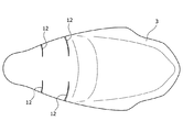
ちなみに、ボトムプレート2aの前端部及び後端部の各々における上面2aについては、略平坦な面であってもよく、あるいは乗員の臀部に沿わせるように適宜段差が付けられた多段面であってもよい。さらに、後述する図12に示すように、ボトムプレート2aの前端部及び後端部のうちの少なくとも一方の上面2a(図12では、後端部の上面2a)において、X字状に形成された2つの凹部2xが設けられていてもよい。凹部2xについては、例えば矩形状溝とし所定方向に長く形成するとよい。このような凹部2xを設けることで、ボトムプレート2の軽量化や凹部2xの形成箇所付近での剛性を高めることが可能となる。
By the way, the
また、ボトムプレート2の前後方向中央部には、図2に示すように、その幅方向中央部が幅方向両端部よりも幾分前方に張り出た張り出し部2cが形成されている。この張り出し部2cの前面2dは、ボトムプレート2の前端部の上面2aと後端部の上面2aとを連絡するように延出している。特に、張り出し部2cの前面2dのうち、ボトムプレート2の後端部により近い方の範囲は、図2に示すように、前後方向と平行な面(水平面)を構成しており、当該水平面上にアクチュエータ7が設置されている。このように張り出し部2cの前面2dのうち、水平面となった範囲にアクチュエータ7を設置することで、アクチュエータ7の設置スペースがより確保し易くなるので、アクチュエータ7の取り付け作業が一段と容易になる。
In addition, as shown in FIG. 2, a protruding
さらに、ボトムプレート2の前端部のうち、その幅方向両端部には、後述する当接部材30が載置されている。そして、ボトムプレート2の上面2aのうち、当接部材30が載置されている部分は、平坦面となっている。さらにまた、図5に示すように、ボトムプレートの上面2aには、幅方向において当接部材30を挟み込む位置に凸状のガイド部2bが前後方向に沿って設けられている。このようなガイド部2bが設けられていることにより、ボトムプレート2の剛性、特に、当接部材30が配置されている領域付近(換言すると、回動プレート8周辺の領域)の剛性を高めることが可能となる。
Further,
回動プレート8は、可動部10を駆動するために回動する金属製又は樹脂製のプレート部材であり、図2に示すように可動部10に合わせて一対設けられている。一対の回動プレート8は、幅方向に間隔を設けた状態でボトムプレート2の前端部の上面2aに取り付けられている。より具体的に説明すると、各回動プレート8は、対応する可動部10の下方位置に配置されている。すなわち、各回動プレート8は、乗員が着座シート1の前側座席に着座した際に乗員の大腿部の下方に位置し、また、図6に示すように、着座シート1の厚み方向においてボトムプレート2とクッション材3との間に挟まれた状態にある。
The
回動プレート8は、羽根(フラップ)型の形状を有し、その外縁のうち、幅方向外側に位置する部分は、横向きV字状に屈曲した屈曲線となっており、幅方向内側に位置する部分は、直線となっている。回動プレート8は、直線形状をなす幅方向内側の端が前後方向に対して若干傾いた姿勢にてボトムプレート2の上面2aに取り付けられている。
The
そして、回動プレート8は、ケーブル9を介してアクチュエータ7からの動力を受け付けると、幅方向内側の端を基点として、幅方向外側の端が昇降するように回動する。具体的に説明すると、可動部10が展開動作を行うとき、回動プレート8は、アクチュエータ7が付与する動力により、その幅方向外側の端が上昇するような回動動作(以下、開動作)を行う。他方、可動部10が格納動作を行うとき、回動プレート8は、その幅方向外側の端が下降するような回動動作(以下、閉動作)を行う。
When the
当接部材30は、矩形片状の部材であり、回動プレート8毎に設けられている。具体的に説明すると、当接部材30は、図5に示すように各回動プレート8に対して一つずつ設けられている。そして、各当接部材30は、回動プレート8とボトムプレート2とに挟まれた位置において、その長辺が前後方向に沿った状態で配置されている。また、各当接部材30は、前後方向における中間部33にて回動プレート8の裏面と当接した状態にある。ここで、中間部33とは、当接部材30のうち、前端部(一端部に相当)31と後端部(他端部に相当)32との間に位置する部分である。なお、中間部33の上面には、回動プレート8に向かって隆起したリブ状の隆起部33aが形成されており、かかる隆起部33aが回動プレート8の裏面と当接している。
The
そして、当接部材30は、回動プレート8を回動させるために動作する。より詳しく説明すると、当接部材30の後端部32は、ボトムプレート2に固定されているのに対し、当接部材30の前端部31は、ボトムプレート2の上面2aに沿って前後方向に移動可能となっている。すなわち、当接部材30は、その前端部31が後端部32に対して進退可能となるように構成されている。そして、当接部材30は、その前端部31が後端部32に向かって移動すると、図7に示すように中間部33が上方(回動プレート8が位置する方)に向けて突出するように屈曲変形する。図7は、当接部材30の動作についての説明図であり、図中の(a)は待機時の状態を、(b)は動作時の状態を、それぞれ示している。
Then, the
以上のような当接部材30の屈曲変形により、中間部33の突出量が徐々に増加していくと、これに伴って回動プレート8と当接した当接部材30の中間部33が回動プレート8を押し上げるようになる。その結果、回動プレート8は、開動作を行うようになる。一方、前端部31が後端部32に対して離間することで当接部材30が屈曲状態から元の状態に復元すると、中間部33の突出量が徐々に減少し、その結果、回動プレート8が閉動作を行うようになる。
When the protruding amount of the
なお、前述したように、幅方向において当接部材30を挟む位置には、ボトムプレート2の上面2aから突出形成されたガイド部2bが設けられている。このガイド部2bは、図5に示すように、当接部材30の前端部31の移動方向である前後方向に沿って形成されている。したがって、前端部31は、ガイド部2bにガイドされながら前後移動することとなり、これにより後端部32に対して適切に近接または離間するようになる。
As described above, the
ケーブル9は、アクチュエータ7から付与される動力を回動プレート8まで伝達する部材であり、厳密には、アクチュエータ7と当接部材30との間を連結している。より具体的に説明すると、ケーブル9は、当接部材30毎に設けられている。一方のケーブル9は、アクチュエータ7から延出しており、図7等に示すように、当該ケーブル9の先端部が一方の当接部材30の前端部31に係止されている。さらに、図7等に示すように、当該ケーブル9の先端部には、他方のケーブル9の末端部が繋がれている。また、他方のケーブル9の先端部は、他方の当接部材30の前端部31に係止されている。
The
そして、アクチュエータ7からの動力により、各ケーブル9が牽引され、または、繰り出される。より具体的に説明すると、アクチュエータ7は、不図示のリールを有し、このリールには一方のケーブル9が巻回されている。そして、アクチュエータ7が上記のリールを回転させることでケーブル9を巻き取ると、当該ケーブル9が牽引されるようになる。この際、リールによって直接牽引されるケーブル9とともに、同ケーブル9に繋がれたもう一つのケーブル9も牽引されるようになる。このように各ケーブル9が牽引されると、ケーブル9の先端部が係止されている当接部材30の前端部31が後端部32に向かって移動する。これにより、当接部材30が回動プレート8を押し上げ、結果として、回動プレート8が開動作を行うようになる。以上のような手順により、アクチュエータ7からの動力が、ケーブル9及び当接部材30を経由して各回動プレート8に伝達される。
Then, each
ところで、ケーブル9は、着座シート1の厚み方向においてボトムプレート2とクッション材3との間に敷設されており、特に本実施形態では、図6に示すようにボトムプレート2の上面2aに沿って敷設されている。
By the way, the
本来、ケーブル9の敷設経路については、その敷設長さがより短くなるようにアクチュエータ7と当接部材30との間を最短距離にて繋ぐ経路とするのが一般的である。ただし、このような経路を採用しようとすると、当該経路用の空間を確保するためにクッション材3とボトムプレート2との間に比較的大きな隙間が形成されることになり、その分、クッション材3(厳密には、ケーブル9の上方に位置する部分)が薄肉となる。こうしたクッション材3の薄肉化により、着座シート1のクッション性が低下してしまう虞がある。これに対して、本実施形態のようにボトムプレート2の上面2aに沿わせてケーブル9を敷設すれば、クッション材3とボトムプレート2との間に大きな隙間が形成されることがなく、クッション材3の厚みを薄肉化することもない。したがって、クッション材3は、本来の厚みにて着座シート1に搭載されるようになる。この結果、クッション材3がその機能を発揮し、着座シート1のクッション性を十分確保することが可能となる。
Originally, the laying route of the
なお、本実施形態では、2本のケーブル9を繋ぎ合わせることで1本のケーブル9として取り扱うことが可能となるため、アクチュエータ7から延び出すケーブル9の本数を1本とすることが可能である。また、アクチュエータ7に直接接続されているケーブル9については、当接部材30の前端部31に向かって延出している部分が前後方向に沿って延出している。これにより、ケーブル9の牽引により当接部材30の前端部31を移動させるときには、引張力がケーブル9から当接部材30の前端部31にスムーズに伝達されるようになる。
In the present embodiment, it is possible to handle the two
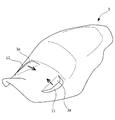
以上までに説明してきた機器(アクチュエータ7、回動プレート8、ケーブル9及び当接部材30)によって構成された駆動機構6により、可動部10の展開動作及び格納動作が実現される。ここで、可動部10の構成について説明すると、可動部10は、クッション材3の前端部に設けられた図8に図示の回動部分3aと、当該回動部分3aを覆う表皮材4とを有する。図8は、クッション材3の斜視図であり、同図では、回動部分3aが上方に向かって回動した状態を図示している。
The
回動部分3aは、クッション材3において回動プレート8の直上位置に位置し、ボトムプレート2との間で回動プレート8を挟む部分である。この回動部分3aは、その下面にて回動プレート8と当接しており、回動プレート8の回動に伴って同様に回動動作を行う。より具体的に説明すると、回動プレート8が回動すると、回動部分3aは、その幅方向内側の端を基点に回動し、例えば、回動プレート8が開動作をする際には幅方向外側の端が上昇するように回動する。
The rotating portion 3 a is a portion located on the
回動部分3aについてより詳しく説明すると、回動部分3aは、クッション材3の前端部に一対形成されている。回動部分3aの形成位置は、幅方向において互いに離れており、かつ、クッション材3の前端部の側端よりも幾分内側にある。回動部分3aは、回動プレート8と同様、羽根(フラップ)型に形成されており、その外縁のうち、幅方向外側に位置する部分は、横向きV字状に屈曲した屈曲線となっている。一方、回動プレート8の外縁のうち、幅方向内側に位置する部分は、直線形状になっており、回動部分3aが回動する際の基点(すなわち、折り曲げ基点)をなしている。
The rotating portion 3a will be described in more detail. A pair of rotating portions 3a are formed at the front end of the
また、回動部分3aは、クッション材3における回動部分3a以外の部分、すなわち、非回動部分とともに一体成形されている。そして、回動部分3aの外縁、換言すると、回動部分3aと非回動部分との境界位置には、切れ込みとしてのスリット11が形成されている。このスリット11は、回動部分3aがスムーズに回動することを目的として形成されたものであり、回動部分3aの外縁に沿って形成されている。より具体的に説明すると、スリット11は、回動時の基点をなしている幅方向内側の部分を除き、回動部分3a全域に亘って形成されており、略横向きV字状に屈曲している。
Further, the rotating portion 3a is integrally formed with a portion of the
そして、上記のスリット11が回動部分3aと非回動部分との境界位置に形成されていることで、上記のスリット11が形成されていない場合と比較して、回動部分3aが回動する際の回動量が増加する。これにより、可動部10が格納状態から展開状態に遷移して当接領域5aが移動する際の移動量を十分に確保することが可能となる。この結果、可動部10が展開状態となって乗員の大腿部を持ち上げながら支持する際、当接領域5aは、より広い面積にて乗員の大腿部と当接するようになり、座圧を分散する効果をより一層好適に発揮することが可能となる。
Since the
以上のように、クッション材3に形成された上記のスリット11は、本実施形態において、可動部10が回動プレート8の回動動作に伴って回動する際の連動性を向上させるための連動性向上部として機能する。換言すると、クッション材3の回動部分3aは、連動性向上部としてのスリット11が形成されていることで、回動プレート8の動作に対して良好に追従することができる。これにより、可動部10の変位量については、当接領域5aが展開位置に位置した状態で可動部10が乗員の大腿部を持ち上げて支持するのに十分な量を確保し、さらに、回動プレート8の動作量を制御して容易に調整することが可能となる。
As described above, the
なお、着座シート1を上方から見たときに、着座シート1の幅方向両端部のうち、スリット11に囲まれた位置にある部位が可動部10に該当する。換言すると、スリット11は、着座シート1の幅方向両端部の各々において、可動部10とそれ以外の部分との境界を形成していることになる。
In addition, when the
また、本実施形態では、上記のスリット11が、回動プレート8の外縁、特に、幅方向外側に位置したV字状の屈曲部分に沿って形成されている。このようにスリット11が回動プレート8の外縁に沿って形成されていれば、回動部分3aの外縁部が回動プレート8の外縁部と当接し易くなるので、回動プレート8によって回動部分3aを動かす(回動させる)ことがより容易になる。この結果、回動部分3aの回動量を確保することが一層容易になり、座圧を分散する効果についても一段と好適に発揮されるようになる。
In addition, in the present embodiment, the
また、本実施形態では、前述のアクチュエータ7が幅方向においてスリット11を避けた位置に配置されている。具体的に説明すると、アクチュエータ7は、スリット11の形成位置よりも幅方向内側、換言すると、一対のスリット11の間に位置している。このようにアクチュエータ7がスリット11から離れていることで、スリット11が奏する効果、すなわち、クッション材3の回動部分3aを回動させ易くする効果がアクチュエータ7により阻害されることなく、好適に発揮されるようになる。
Further, in the present embodiment, the
なお、クッション材3の裏面、すなわち、ボトムプレート2との対向面において、回動部分3aの外縁の幅方向内側部分(回動時の基点となる部分)には、図4に示すように半円柱状に形成された窪み3bが形成されている。この窪み3bが回動時の基点となる部分の裏面に形成されていることで、回動部分3aが更に変形し易くなり、結果として、座圧を分散する効果が益々好適に発揮されるようになっている。
As shown in FIG. 4, on the back surface of the
さらに、本実施形態では、回動プレート8がその幅方向一端側に設けられた回動軸8aを中心として回動するように構成されている。そして、着座シート1に乗員が着座している状態では、幅方向において、回動プレート8や回動軸8aが配置されている位置が、乗員の坐骨が存する範囲から外れた位置となっている。これにより、坐骨付近での座圧を分散させることが可能となる。かかる効果について図9を参照しながら説明する。図9は、乗員の坐骨と回動プレート8との位置関係を示した模式断面図である。
Further, in the present embodiment, the
着座シート1に乗員が着座すると、乗員の臀部が載ることによりクッション材3が撓む(歪む)ようになる。この際、図9に示すように、乗員の臀部のうち、坐骨が位置する部分が載る箇所で撓み量が最大となる。一方、回動プレート8及びその回動軸8aは、幅方向において乗員の坐骨が存する範囲(図9中、記号Zにて示された範囲)から外れた位置、より具体的には、当該範囲Zよりも幅方向外側に配置されている。このような位置関係により、回動プレート8は、乗員に違和感を与えることなく適切に回動することが可能となる。また、範囲Zから外れた位置にて回動プレート8が回動することで、回動プレート8の回動によって着座面が変形した際に当該着座面と乗員の大腿部との接触面積が増加する。この結果、坐骨付近での座圧がより分散されるようになり、坐骨付近での座圧上昇時に乗員の臀部に掛かる負荷を、軽減することが可能となる。
When the occupant is seated on the
次に、可動部10の動作を自動二輪車の走行状態に応じて実行するための構成について図10を参照しながら説明する。図10は、本座席装置Sの構成を制御面から示したブロック図である。本座席装置Sは、図10に示すように、上述した駆動機構6を制御する制御機器としてのECU(Electronic Control Unit)20を備えている。このECU20は、自動二輪車本体に備え付けられており、自動二輪車の走行速度に応じて可動部10の状態を自動制御するものである。より具体的に説明すると、ECU20は、自動二輪車の走行速度に応じてアクチュエータ7を制御する。これにより、一対の回動プレート8が走行速度に対応する動作として閉動作又は開動作を行うようになる。この結果、可動部10は、走行速度が所定の速度以上となると展開動作を開始し、走行速度が減速して所定の速度以下となると格納動作を開始するようになる。
Next, a configuration for executing the operation of the
すなわち、本座席装置Sは、自動二輪車の走行速度をモニタリングしており、具体的には、速度検知部としての速度センサ22を備えている。速度センサ22は、走行速度を検知すると、その検知結果に応じた信号を出力する。ECU20は、速度センサ22からの出力信号を受信すると、当該信号から速度センサ22の検知結果(すなわち、自動二輪車の走行速度)を特定する。
That is, the seat apparatus S monitors the traveling speed of the motorcycle, and specifically includes the
速度センサ22が検知した走行速度を特定した後、ECU20は、当該走行速度をECU20のメモリ21に記憶された閾値と対比する。ここで、メモリ21に記憶されている閾値は、2種類あり、一つは、展開動作を実行するか否かを判断する際に用いる閾値、すなわち、走行時用閾値である。もう一つは、格納動作を実行するか否かを判断する際に用いる閾値、すなわち、減速時用閾値である。これら2つの閾値は、いずれも予め設定された値となっており、その一例を挙げて説明すると、走行時用閾値は、時速70〜90kmの範囲で設定され、特に本実施形態では時速80kmに設定されている。また、減速時用閾値は、時速30〜50kmの範囲で設定され、特に本実施形態では時速40kmに設定されている。なお、走行時用閾値及び減速時用閾値については、いずれも上記の値に限定されるものではなく、任意の値に設定することが可能である。
After identifying the traveling speed detected by the
また、本実施形態では、メモリ21に記憶された各閾値が事後的に変更可能となっている。具体的に説明すると、自動二輪車の所定箇所には、スイッチあるいはレバー等からなる入力手段23が搭載されており、かかる入力手段23が乗員による閾値の変更操作を受け付けると、ECU20が、メモリ21に記憶された閾値を変更後の閾値に上書き更新する。このように事後的に閾値を変更することが可能であれば、ユーザ(乗員)の好みに合わせて制御条件が設定されるようになる。
Further, in this embodiment, the threshold values stored in the
そして、ECU20は、走行速度を各閾値と対比して所定の条件を満たしているときに、アクチュエータ7を制御して可動部10の状態を切り替えることとしている。より具体的に説明すると、自動二輪車が停止状態から走行状態に移行し、走行速度が走行時用閾値以上となると、ECU20は、可動部10が展開動作を開始するようにアクチュエータ7を制御する。これにより、着座シート1の外表面5中の当接領域5aが格納位置から展開位置に向かって移動し始めるようになる。そして、当接領域5aが展開位置に達した時点で、ECU20は、アクチュエータ7を停止する。かかる時点では、前側座席に着座している乗員の大腿部が可動部10により持ち上げられた状態で支持されるようになる。この結果、自動二輪車の走行時には乗員から着座シート1に掛かる座圧が分散されるようになる。
Then, the
一方、自動二輪車が減速して走行速度が減速時用閾値以下となると、ECU20は、可動部10が格納動作を開始するようにアクチュエータ7を制御する。これにより、当接領域5aは、展開位置から格納位置に向かって移動するようになる。なお、本実施形態において、ECU20は、走行速度が所定速度まで減速した時点、厳密には自動二輪車が停止した時点で当接領域5aが格納位置に到達するようにアクチュエータ7を制御する。この結果、自動二輪車の走行中には可動部10により持ち上げられていた乗員の大腿部が減速度合いに応じて徐々に降ろされていき、停止時には乗員の足が地面に付くようになる。
On the other hand, when the motorcycle decelerates and the traveling speed becomes equal to or lower than the threshold value for deceleration, the
ところで、本座席装置Sは、図10に示すように、乗員により操作される操作スイッチ24を更に備えている。操作スイッチ24は、スイッチの一例であり、自動二輪車に設けられた不図示の操作パネルに搭載されており、オンオフ自在である。
By the way, the seat apparatus S further includes an
そして、操作スイッチ24のオンオフに応じて、ECU20によるアクチュエータ7の制御の有無が切り替わることとなっている。具体的に説明すると、操作スイッチ24がオンになっている状態のみにおいて、ECU20は、速度センサ22が検知した走行速度に応じて当接領域5aの位置が切り替わるようにアクチュエータ7を自動制御する。すなわち、ECU20を通じた当接領域5aの位置の自動調整については、操作スイッチ24がオンになっているときにのみ実行され、操作スイッチ24がオフになっているときには実行されないことになっている。このようにECU20の制御の有無が操作スイッチ24の操作によって自在に切り替え可能となっていることで、ユーザ(乗員)は、自分の意思で当接領域5aの位置調整の有無を設定することが可能となる。そして、操作スイッチ24がオンとなっているときに限り当接領域5aの位置調整がなされるので、その時点でのモードが、「調整有り」のモードであるのか「調整無し」のモードであるのかを確認することが可能となる。
The control of the
<<当接領域の位置調整に関する処理の手順>>
次に、自動二輪車の走行速度に応じて当接領域5aの位置を調整するための処理(以下、シート形状調整処理)について、図11を参照しながら、その手順について説明する。図11は、シート形状調整処理の手順を示す図である。シート形状調整処理は、図11に示すように、操作スイッチ24がオフ状態からオン状態に切り替わることをトリガーとして開始される(S001)。このスイッチ操作は、通常、乗員が自動二輪車に乗り込んで着座シート1の前側座席に着座した時点で行われる。なお、本工程S001の実行時点では、可動部10が格納状態にあり、換言すると、着座シート1の外表面5中の当接領域5aが格納位置にあり、乗員の足が地面に付き易くなっている。<<Procedure of processing regarding position adjustment of contact area>>
Next, the procedure for adjusting the position of the
シート形状調整処理が開始されると、以降、自動二輪車の走行速度のモニタリング、及び、走行速度に応じた当接領域5aの位置調整が随時実行される。具体的に説明すると、自動二輪車が走行し始めて、走行速度が徐々に加速していくと、速度センサ22が当該走行速度を定期的に検知し、その検知結果を示す信号を出力する(S002)。一方で、ECU20が、速度センサ22から受信した出力信号に基づいて走行速度を特定するとともに、メモリ21に記憶された走行時用閾値を読み出した上で、特定した走行速度が走行時用閾値以上となっているか否かを判定する(S003)。
When the seat shape adjustment processing is started, thereafter, the traveling speed of the motorcycle is monitored and the position adjustment of the
そして、ECU20は、走行速度が走行時用閾値以上となっていると判定したとき、アクチュエータ7を制御して回動プレート8に開動作を実行させる。このようにECU20によるアクチュエータ7の制御が開始されると、可動部10が展開動作を実行し始め、格納位置にあった当接領域5aが展開位置に向かって移動するようになる(S004)。
When the
当接領域5aが展開位置に到達すると、当接領域5aによって乗員の大腿部が持ち上げられた状態で支持されるようになる。これにより、前述した通り、自動二輪車の走行中の座圧が分散され、結果として乗員への負担が軽減されることとなる。つまり、自動二輪車が比較的早い速度にて走行している間には、着座シート1の着座面の形状を変更させることで乗員の大腿部が持ち上げられ、この結果、座圧が適当に分散するようになる。以降、走行速度が走行時用閾値以上の速度を維持し続ける間、当接領域5aは、展開位置に保持されることになる。
When the
一方、速度センサ22は、引き続き走行速度を定期的に検知し、検知結果を示す信号を出力する(S005)。そして、走行状態の自動二輪車が停止するために減速を開始した際、ECU20は、速度センサ22から受信した出力信号に基づいて走行速度を特定し、メモリ21に記憶された減速時用閾値を読み出した上で、特定した走行速度が減速時用閾値以下となっているか否かを判定する(S006)。かかる工程S006において、走行速度が減速時用閾値以下であると判定されたとき、ECU20は、アクチュエータ7を制御して回動プレート8に閉動作を実行させる(S007)。これにより、可動部10が格納動作を実行し始め、展開位置にあった当接領域5aが格納位置に向かって移動するようになる。
On the other hand, the
なお、本実施形態において、ECU20は、自動二輪車が停止した時点で当接領域5aが格納位置に至るようにアクチュエータ7を制御する。より具体的に説明すると、ECU20は、自動二輪車の減速度合いに応じて当接領域5aの移動速度の変化度合い(厳密には加速度)が変わるようにアクチュエータ7を制御する。このように自動二輪車が停止した時点で、可動部10が格納状態となり当接領域5aが格納位置に達するようになる。この結果、自動二輪車の停止時には、当接領域5aにより持ち上げられていた乗員の大腿部が下方に下ろされて、足が地面に付き易くなる。
In the present embodiment, the
以上までに説明したシート形状調整処理中の各工程S002〜S007が、自動二輪車に乗員が乗車している間、厳密には、操作スイッチ24がオン状態となっている間、繰り返し実行される。そして、乗員が操作スイッチ24をオフにした上で自動二輪車から降車した時点でシート形状調整処理が終了する。
The steps S002 to S007 in the seat shape adjusting process described above are repeatedly executed while the occupant is on the motorcycle, strictly speaking, while the
<<駆動機構の変形例について>>
既に説明した実施形態(具体的には、図5〜7に図示した構成例であって、以下、先の実施形態)では、アクチュエータ7、回動プレート8、ケーブル9及び当接部材30によって構成された駆動機構6について説明した。また、先の実施形態では、回動プレート8を開方向に回動させるにあたって山形に屈曲変形する当接部材30を説明した。ただし、駆動機構6の構成、特に当接部材30の構成については、先の実施形態で説明したものに限定されるものではない。以下では、駆動機構の変形例について図12〜22を参照しながら説明することとする。<<About modification of drive mechanism>>
In the above-described embodiment (specifically, the configuration example illustrated in FIGS. 5 to 7, which will be hereinafter referred to as the previous embodiment), the
図12は、変形例に係る駆動機構106を示す斜視図である。なお、図12では、図示を分かり易くするために、ケーブル109及びケーブル収容溝2gの記載を省略している。図13〜図15は、変形例に係る動作体としての回動プレート108を側方から見たときの図である。図16及び図17は、変形例に係る当接部材としての当接カム130及び収容部121を示した斜視図である。図18は、当接カム130の側面図である。図19は、変形例に係るケーブル109の敷設経路を示した図である。図20は、ケーブル収容溝123の一部を拡大した図である。図21は、回動プレート108周辺の構成を示した図である。図22は、着座シート1を図21中のA−A断面で切断したときの断面図である。
FIG. 12 is a perspective view showing the
変形例に係る駆動機構106は、先の実施形態に係る駆動機構6と同様に、アクチュエータ107、回動プレート108、ケーブル109及び当接部材としての当接カム130を有する。また、変形例に係る駆動機構106は、押圧部材の一例として図12に図示の押さえ板150を有する。以下、変形例に係る駆動機構106の各構成部品について説明する。なお、変形例に係る駆動機構106の各構成部品に関する構成のうち、先の実施形態と共通する内容については説明を省略し、変形例特有の内容についてのみ説明することとする。
The
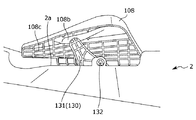
変形例に係る回動プレート108(以下、単に回動プレート108という)は、図13乃至15に示すように若干の厚みを有する構成となっている。具体的に説明すると、回動プレート108のうち、幅方向内側に位置する端部は、前後方向に沿う回動軸108aによって支持されている。また、回動プレート108自体が3次元状に屈曲しており、詳しく説明すると、幅方向外側の端部の底を幅方向内側の端部の底よりも高くするための段差が形成されるように屈曲している。さらに、図13や図21に示すように、回動プレート108の幅方向外側の端部は、略直角に折れ曲がっている。なお、図13に示すように、回動プレート108の幅方向外側の端部のうち、折れ曲がった部分の先端(下端)は、凹凸を形成することなく略平坦に延出している。
The
また、回動プレート108は、図14及び15に示すように、後述する当接カム130の突出端部131が回動プレート108の裏面に当接して回動プレート108を押し上げることによって開動作を実行するようになる。なお、同図に示すように、回動プレート108の裏面(すなわち、当接カム130と対向する側の面)のうち、突出端部131が当接する領域は、当接カム130に向かって凸状に突出している。この凸状部分108bが形成されていることで、回動プレート108のうち、当接カム130が当接する部分付近の剛性がより高められている。ちなみに、凸状部分108bは、回動プレート108の裏面のうち、幅方向外側の領域に形成されている。
Further, as shown in FIGS. 14 and 15, the
さらに、図14及び15に示すように、回動プレート108の裏面には、上述した凸状部分108bが形成された領域を除き、格子状の補強リブ108cが形成されている。これにより、回動プレート108の剛性を確保しつつ、より軽量化された回動プレート108が実現されることになる。なお、図14及び15に図示した構成では矩形型の格子をなすように補強リブ108cが形成されているが、これに限定されるものではない。補強リブ108cがなす格子の形状については、ハニカム型や三角形型であってもよい。
Further, as shown in FIGS. 14 and 15, on the back surface of the
また、変形例では、先の実施形態と同様、回動プレート108が幅方向内側に位置する端の方に設けられた回動軸108aを中心として回動する。一方で、回動プレート108の幅方向端部には、図12に示すように、押圧部材としての押さえ板150が回動プレート108と重なるように設けられている。この押さえ板150は、例えば矩形状の板バネ片からなり、幅方向において回動軸108aを跨いだ状態で回動プレート108の幅方向内側の端部をボトムプレート2に向かって押圧するものである。
Further, in the modified example, as in the previous embodiment, the
つまり、回動プレート108は、通常時には、バタつかないように押さえ板150の押圧力によってボトムプレート2に押さえ付けられる一方で、開動作時には当該押圧力に抗して回動動作を行うようになる。このように回動プレート108が動作していない間、回動プレート108のバタツキが抑えられる結果、着座シート1の外観(特に着座面の形状)が良好に保持されるようになる。なお、図12に図示した構成では、矩形状の押さえ板150によって回動プレート108を押さえつけることとしたが、これに限定されるものではない。回動プレート108のバタツキを抑えるために回動プレート108を押さえ付けるものであればよく、例えば、回動軸108aにコイルばねをセットし、当該コイルばねの一端を回動プレート108の幅方向端部に固定することで回動プレート108を押さえ付けてもよい。
In other words, the
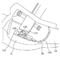
当接カム130は、図16及び17に示すように、ボトムプレート2に形成された窪み状の収容部121に収容された部品である。収容部121について説明すると、収容部121は、ボトムプレート2の上面2aのうち、各回動プレート108の直下位置に形成されており、上端が矩形状の開口端となった収容空間をなしている。この収容空間は、当接カム130全体を収容するのに十分な幅及び深さを有している。
As shown in FIGS. 16 and 17, the
当接カム130は、図18に示すように側面視で略半円型の外形形状を有しており、その前側の先端部は、幾分前方に隆起するように突出している。以下、当接カム130のうち、前側の先端部を突出端部131と呼ぶこととする。また、当接カム130の外表面のうち、幅方向の端に位置する面には、図18に示すように格子状の補強リブ130aが形成されている。これにより、当接カム130の剛性を確保しつつ、より軽量化された当接カム130が実現されることになる。なお、図18に図示した構成では略矩形型や扇型の格子をなすように補強リブ130aが形成されているが、これに限定されるものではない。補強リブ130aがなす格子の形状については、ハニカム型や三角形型であってもよい。
The
また、当接カム130は、上記収容空間内において回動自在な状態で収容されている。具体的に説明すると、当接カム130の上端部のうち、前後方向において中央位置よりもやや後ろ寄りに位置する部分にはカム側回動軸132が設けられている。このカム側回動軸132は、その軸方向が幅方向に沿った状態でボトムプレート2(厳密には、収容部121付近の部分)に取り付けられている。そして、当接カム130は、カム側回動軸132周りに回動することでその姿勢を切り替える。
The
より詳しく説明すると、通常時、当接カム130は、図18において実線にて示す姿勢にあり、具体的には、突出端部131がやや下を向いた姿勢にある。かかる姿勢にあるとき、当接カム130は、その全体が図16に示すように収容部121内に収容された状態となっている。一方、当接カム130は、突出端部131が上方に向かうように回動して当該回動範囲の終端位置に達すると、図18において破線にて示す姿勢、具体的には突出端部131が回動軸132よりも幾分上方に位置した姿勢となる。かかる姿勢にあるとき、当接カム130は、突出端部131が図17に示すように収容部121の開口端(上端)から収容部121の外へ突き出た状態となっている。換言すると、当接カム130は、当接カム130の一部分が収容部121の外へ突き出る位置まで回動することになる。
More specifically, in the normal state, the
そして、突出端部131が収容部121の外に突き出るようになると、突出端部131の突端(先端)が回動プレート108の裏面に形成された凸状部分108bに当接する。その後、当接カム130がそれまでの回動方向と同じ方向に更に回動すると、回動プレート108の幅方向外側の端部が、図14及び15に示すように、突出端部131によって押し上げられるようになる。これにより、回動プレート108が回動動作を行い、可動部10が展開動作を行うようになる。
Then, when the
以上のように構成された当接カム130であれば、通常時(厳密には、着座シート1の外表面5のうち、当接領域5aが格納位置に位置するとき)には収容部121内に収めておくことが可能である。また、可動部10に展開動作を行わせる際には、当接カム130を回動させて当接カム130の突出端部131を収容部121の外に突出させることで、回動プレート108と当接させて当該回動プレート108を押し上げる。このような構成によれば、当接カム130の配置スペースを省スペース化することが可能となり、着座シート1のレイアウトが好適に設計されたものとなる。
With the
変形例に係るアクチュエータ107(以下、単にアクチュエータ107という)は、先の実施形態に係るアクチュエータ7と同様、ケーブル109と接続されており、ケーブル109を牽引することで回動プレート108に対して動力(回動力)を付与する。より詳しく説明すると、アクチュエータ107は、図19に示すように、ボトムプレート2の上面2aの前後方向中央部において、幅方向中央部に位置するように配置されている。また、アクチュエータ107に接続されたケーブル109は、同図に示すように二股状に分岐しており、そのうちの一方が、幅方向一端側の当接カム130に固定されており、他方が、幅方向他端側の当接カム130に固定されている。
The
そして、アクチュエータ107がケーブル109を牽引すると、ケーブル109を通じて各当接カム130に回動力が付与されるようになる。これにより、各当接カム130が回動し、各当接カム130の姿勢が、カム全体が収容部121内に収容された姿勢(以下、収容姿勢)から、突出端部131が収容部121の外に突き出た姿勢(以下、突出姿勢)へ切り替わる。このような当接カム130の回動動作に連動して回動プレート108が開動作を行うようになる。
Then, when the
なお、変形例では、図19に示すように、幅方向一端側の当接カム130に固定されたケーブル109と、幅方向他端側の当接カム130に固定されたケーブル109と、が別々に設けられている。すなわち、変形例では、先の実施形態と異なり、アクチュエータ107からの動力を幅方向一端部に設けられた回動プレート108に伝達するためのケーブル109と、幅方向他端部に設けられた回動プレート108に伝達するためのケーブル109と、が分かれて設けられている。
In the modification, as shown in FIG. 19, the
また、上記2つのケーブル109は、図19に示すように、着座シート1の幅方向中央を挟んで対称的に敷設されている。そして、各ケーブル109は、幅方向両側に設けられた当接カム130のうち、対応する当接カム130のみに固定されている。換言すると、それぞれの回動プレート108には、回動プレート108別に設けられたケーブル109のうち、対応する一方のケーブル109のみを通じてアクチュエータ107からの動力が伝達されることになる。このような構成によれば、先の実施形態のように2つのケーブル9を直鎖状に繋げて用いる場合と比較して、それぞれのケーブル109を敷設する際に、敷設経路の中途位置での曲げをより少なくすることが可能になる。これにより、ケーブル牽引時のロス(牽引ロス)が抑えられ、各回動プレート108への動力伝達が適切に行われるようになる。
Further, the two
ここで、各ケーブル109の敷設経路について図19を参照しながら説明すると、各ケーブル109は、対応する当接カム130の後方位置から当該当接カム130の前方位置に回り込むように敷設されている。そして、各ケーブル109は、対応する当接カム130に対して、当該当接カム130の前側から繋ぎ込まれており、各ケーブル109の末端部が当接カム130の後端上部に固定されている。したがって、各ケーブル109が牽引されると、対応する当接カム130の後端上部が下降しながら前方に向かうように移動する。これにより、当接カム130は、図18中、実線にて示した収容姿勢から破線にて示した突出姿勢へ姿勢が切り替わるように回動する。
Here, the laying route of each
なお、変形例では、上記のように各ケーブル109を敷設すべく、ボトムプレート2の上面2aにケーブル収容溝2gが形成されている。このケーブル収容溝2gは、ケーブル109をボトムプレート2の上面2aに沿って敷設するために形成された溝であり、図19に示すように、ケーブル109毎に形成されている。各ケーブル収容溝2gは、幅方向中央部から延出し、具体的には前後方向において収容部121の形成範囲に差し掛かる位置から前方に延出している。そして、各ケーブル収容溝2gは、前後方向において収容部121の形成範囲よりも前方位置でU字状に屈曲して収容部121の前端に繋がっている。
In the modification, the
また、ケーブル収容溝2gは、ケーブル109を収容するのに適した幅及び深さを有している。そして、ケーブル109は、ケーブル収容溝2gに収容されることで規定の経路にて敷設されるようになる。
Further, the
さらに、ケーブル収容溝2gの内壁のうちの一面(例えば、側壁面)には、図20に図示した突起状の凸部2hが形成されている。この凸部2hは、ケーブル収容溝2gの進行方向において一定間隔毎に形成されている。そして、ケーブル収容溝2g内にケーブル109が収容されると、各凸部2hが当該ケーブル109と当接する。より具体的に説明すると、ケーブル収容溝2g内にケーブル109が収容されると、各凸部2hは、凸部2hが形成されている側とは反対側にある内壁面とともに上記のケーブル109を挟み込むようになる。これにより、ケーブル収容溝2g内に収容されたケーブル109は、溝内において位置決めされるようになる。このようにケーブル収容溝2gの内壁面に位置決め用の凸部2hが形成されることで、ケーブル109の敷設をよりスムーズに行うことが可能となり、結果として、着座シート1の組立作業における作業効率が向上することとなる。
Furthermore, a projection-shaped
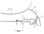
ところで、変形例では、図19や図21に示すように、ボトムプレート2が、収容部121よりも幅方向外側に数cmほど張り出した部分(すなわち、当接カム130よりも幅方向外側に位置する部分)を有する。かかる部分は、上面(表皮材と同じ側にある面)が平坦面となった平坦部2iを構成している。一方、図22に示すように、クッション材3において平坦部2iの上方位置には吊り込み溝3sが形成されており、当該吊り込み溝3sに表皮材4(厳密には、表皮材4の一断片)が吊り込まれている。以上のように変形例では、平坦部2iの上方に確保されたスペースを利用して表皮材4が吊り込み溝3s内に吊り込む。この結果、表皮材4の吊り込み作業がより効率よく行われるようになる。
By the way, in the modified example, as shown in FIG. 19 and FIG. 21, the
なお、吊り込み作業の作業性の観点から、吊り込み溝3sについてはやや幅広に形成されることになっている。かかる場合には、着座シート1の見た目(意匠性)を向上させる目的から、図22に示すように、封止布4a(いわゆるボロ隠し)を吊り込み溝3s内に配置するのが望ましい。
In addition, from the viewpoint of workability of the hanging work, the hanging
また、変形例では、回動プレート108が回動して可動部10が展開動作を実行する際、表皮材4、特に、前述した吊り込み溝3s内に吊り込まれた表皮材4の端末部が良好に追従する。この結果、回動プレート108及び可動部10の動きに伴って表皮材4に弛みが発生するのを抑え、着座シート1の外観を良好に保持することが可能となる。かかる効果を実現するための構成について、以下、図22を参照しながら説明する。
Further, in the modification, when the
先ず、吊り込み溝3sについて改めて説明する。吊り込み溝3sは、ボトムプレート2の平坦部2iの上方に形成されている。そして、吊り込み溝3sには、その上端に形成された開口を通じて表皮材4の端末部が吊り込まれている。より具体的に説明すると、表皮材4を構成する断片のうち、幅方向においてより外側に位置する断片(以下、外側断片4m)の端末部と、幅方向においてより内側に位置する断片(以下、内側断片4n)の端末部と、がそれぞれ吊り込まれている。
First, the hanging
また、吊り込み溝3sには、クッション材3の下端まで貫通した部分が適宜な間隔で存在している。また、クッション材3のうち、吊り込み溝3sが貫通している部分の真下には、平坦部2iに形成された貫通孔が位置している。この貫通孔には、図22に図示の留め具Tの先端部が挿入されて吊り込み溝3s内に突き出ている。そして、溝内に突き出た留め具Tの先端部には、外側断片4mの端末部が引っ掛けられて固定されている。
Further, in the suspending
また、吊り込み溝3sは、前述したように幅広に形成されている。特に、吊り込み溝3sの幅方向両端のうち、より内側にある端は、回動プレート8の幅方向端(厳密には、外側の端)の直近に位置している。かかる吊り込み溝3sの端に位置する内壁面、すなわち、幅方向内側に位置する吊り込み溝3sの側壁に沿って内側断片4nの端末部が吊り込まれている。
Further, the hanging
以上のように構成された吊り込み溝3sに表皮材4を吊り込んでなる着座シート1において、回動プレート108が開動作して可動部10が展開動作を実行すると、表皮材4、具体的には内側断片4nが連動して動くことになる。このとき、内側断片4nが外側断片4mと同様に吊り込み溝3s内に突き出た留め具Tに固定されているとすると、回動プレート108及び可動部10の動作に伴って内側断片4nに弛みが生じる可能性がある。このような弛みがあると、シートの外観を損ねてしまうことになる。
In the
そこで、変形例では、回動プレート108及び可動部10が動いた際に内側断片4nに弛みが生じるのを抑えるために、図22に示すように、内側断片4nの端末部がタッカー若しくはステイプラー等によって回動プレート108の端部(幅方向外側の端部)に固定されている。これにより、内側断片4nは、回動プレート108が回動する際に回動プレート108と一体的に動作するようになる。このように内側断片4nが回動プレート108に固定されて回動プレート108と一体的に動くことで、内側断片4nは、適切に張られた状態のまま動くことが可能となる。つまり、回動プレート108及び可動部10の動作に伴って内側断片4nに弛みが生じるのを抑制することが可能となる。
Therefore, in a modified example, in order to prevent the
なお、回動プレート108に表皮材4の端末部を固定して表皮材4の弛みを抑える構成については、自動二輪車や自動三輪車のシートに限定されるものではない。すなわち、シートの着座面の形状を変更するために回動プレート等の動作体を動かすシートであれば上記の構成を適用することが可能である。例えば、自動車に搭載された車両用シートであってランバーサポート機能を備えたもの、すなわち、シート中の腰部を支える部分が回動プレートの動きによって前方に隆起するように動く車両用シートにも上記の構成は適用可能である。なお、車両用シートへの適用例については、図22と略同様の構成、厳密には、図22中のボトムプレート2を車両用シートの構成部品であるシートフレームに置換した構成によって実現可能となる。
Note that the configuration of fixing the end portion of the
ところで、変形例に係るクッション材3には、平坦部2iの上方に位置する吊り込み溝3s以外にも吊り込み溝3tが形成されている。かかる吊り込み溝3tは、図22に示すように、幅方向において吊り込み溝3sよりも内側に形成されており、より詳しくは、回動プレート108の幅方向端(厳密には、より内側の端)の直ぐ脇に位置している。このような位置に吊り込み溝3tを形成することにより、変形例では、表皮材4を適切に吊り込むことが可能となり、さらに回動プレート108がスムーズに回動するようになる。かかる内容について、以下、図22を参照しながら説明する。
By the way, in the
吊り込み溝3tの基本的構成は、先に説明した吊り込み溝3sと同様である。具体的に説明すると、吊り込み溝3tには、クッション材3の下端まで貫通した部分が適宜な間隔で存在しており、当該貫通している部分の真下には、ボトムプレート2に形成された貫通孔が位置している。この貫通孔には留め具Tの先端部が挿入されて吊り込み溝3t内に突き出ている。そして、溝内に突き出た留め具Tの先端部に表皮材4の端末部が引っ掛けられて固定されている。
The basic structure of the hanging
なお、吊り込み溝3tは、比較的深い溝となっているため、より好適に表皮材4を吊り込むことが可能である。一方、深い吊り込み溝3tをクッション材3に形成する場合、その形成位置によっては、回動プレート108の回動動作に支障を及ぼす虞がある。反対に、適切な形成位置に上記の吊り込み溝3tを形成した場合には、回動プレート108がスムーズに回動するようになる。
Since the suspending
そこで、変形例では、図22に示すように、吊り込み溝3tが、クッション材3の厚み方向において回動プレート108が存する範囲に達するように形成されている。さらに、吊り込み溝3tは、幅方向において回動プレート108の端の脇位置を通るように形成されている。具体的に説明すると、吊り込み溝3tは、幅方向において回動プレート108よりも内側に位置し、且つ、回動プレート108の幅方向内側の端と隣り合うように形成されている。
Therefore, in the modified example, as shown in FIG. 22, the hanging
以上のような形成位置に吊り込み溝3tが形成されることで、回動プレート108は、よりスムーズに回動することが可能となる。より詳しく説明すると、上記の形成位置に吊り込み溝3tが形成された構成では、回動プレート108が回動する際、吊り込み溝3t内に吊り込まれた表皮材4に対して回動プレート108が干渉することがない。また、深溝の吊り込み溝3tが、回動プレート108の回動支点である回動軸108aの直ぐ脇に位置する。このため、吊り込み溝3tが、クッション材3中、回動プレート108の動作に連動して動く部分(すなわち、回動部分3a)が動く際の支点として機能するようになる。以上により、回動プレート108は、よりスムーズに回動することが可能となる。
By forming the hanging
なお、回動プレート108及びクッション材3中の回動部分3aがスムーズに回動するように吊り込み溝3tを形成する構成については、自動二輪車や自動三輪車のシートに限定されるものではない。すなわち、シートの着座面の形状を変更するために回動プレート等の動作体を動かしてクッション材の一部を動かすシートであれば上記の構成を適用することが可能である。例えば、自動車に搭載された車両用シートであってランバーサポート機能を備えたもの、すなわち、シート中の腰部を支える部分が回動プレートの動きによって前方に隆起するように動く車両用シートにも上記の構成は適用可能である。なお、車両用シートへの適用例については、図22と略同様の構成、厳密には、図22中のボトムプレート2を車両用シートの構成部品であるシートフレームに置換した構成によって実現可能となる。
The configuration in which the hanging
<<その他の実施形態>>
上記の実施形態では、主として本発明の座席装置について説明した。ただし、上記の実施形態は、本発明の理解を容易にするためのものであり、本発明を限定するものではない。本発明は、その趣旨を逸脱することなく、変更、改良され得ると共に、本発明にはその等価物が含まれることは勿論である。<<Other Embodiments>>
In the above embodiment, the seat device of the present invention has been mainly described. However, the above embodiment is for facilitating the understanding of the present invention and does not limit the present invention. The present invention can be modified and improved without departing from the spirit of the invention, and it goes without saying that the present invention includes equivalents thereof.
また、上記の実施形態では、ECU20によるアクチュエータ7の制御の有無を切り替えるためにオンオフするスイッチの一例として、乗員により操作される操作スイッチ24を例に挙げて説明した。ただし、スイッチについては上記の操作スイッチ24に限定されず、他のスイッチを用いることとしてもよい。例えば、着座シート1における乗員の着座の有無を検出するものであってもよい。具体的に説明すると、着座シート1に圧力センサ(不図示)を搭載し、かかる圧力センサが、乗員の着座によって着座シート1に掛かる圧力(座圧)が所定値以上になったときにオンし、これに伴って信号をECU20に向けて出力する構成も考えられる。かかる構成においても、上記の実施形態と同様、ECU20が圧力センサからの出力信号を受信したときにのみ自動二輪車の走行速度に応じた当接領域5aの位置調整を実行するとよい。以上のような構成であれば、当接領域5aの位置を自動調整する際のトリガーとなる操作(具体的には操作スイッチ24のオンオフ操作)を乗員に対して要することなく、乗員が着座シート1に着座しさえすればよいこととなる。
Further, in the above-described embodiment, the
また、上記の実施形態では、乗員が操作スイッチ24をオンにすると、以降、ECU20が自動二輪車の走行速度に応じて当接領域5aの位置を自動的に調整することとしたが、これに限定されるものではない。つまり、当接領域5aの位置調整については、乗員の操作を受け付けて実行する構成も考えられる。以下、乗員の操作を受け付けて当接領域5aの位置を調整する手順について図23を参照しながら説明する。図23は、シート形状調整処理の手順の変更例を示す図である。
乗員の操作を受け付けて当接領域5aの位置を調整する構成では、図23に示すように、着座シート1に着座している乗員が操作スイッチ24をオンオフすると、これに連動して当接領域5aの位置が切り替わる。より詳しく説明すると、乗員が操作スイッチ24をオンすると(S011)、操作スイッチ24の状態を示す信号がECU20に出力される。ECU20は、かかる出力信号を受信すると、アクチュエータ7を制御して回動プレート8に開動作を実行させる。これにより、可動部10が展開動作を実行し始め、格納位置にあった当接領域5aが展開位置に向かって移動するようになる(S012)。他方、乗員が操作スイッチ24をオフすると(S013)、ECU20が、操作スイッチ24の状態の切り替えに連動する形でアクチュエータ7を制御して回動プレート8に閉動作を実行させる。これにより可動部10が格納動作を実行し始め(S014)、展開位置にあった当接領域5aが格納位置に向かって移動するようになる。
以上のように、当接領域5aの位置調整は、自動二輪車の走行速度に応じて自動的になされるケースに限定されず、乗員によりマニュアル操作されることとしてもよい。Further, in the above-described embodiment, after the occupant turns on the
In the configuration that receives the operation of the occupant and adjusts the position of the
As described above, the position adjustment of the
さらに、上記の実施形態では、当接領域5aの位置として選択可能な位置が格納位置及び展開位置のみであったが、これに限定されるものではない。つまり、当接領域5aの位置については、乗員の好みに応じて段階的に調整可能となっていてもよい。より具体的に説明すると、操作スイッチ24が、回動プレート8の動作量を調整するために操作される動作量調整用スイッチとして機能し、例えば、操作スイッチ24を押す時間が長くなるほど大きな動作量に設定されるようになっている。一方、ECU20は、操作スイッチ24の操作を通じて調整された動作量だけ回動プレート8が動作するようにアクチュエータ7を制御する。これにより、当接領域5aは、操作スイッチ24の操作(具体的には、スイッチ押し時間)に応じた位置へ移動するようになる。すなわち、当接領域5aの位置が乗員の好みに応じて段階的に調整されることになる。
Furthermore, in the above embodiment, the positions that can be selected as the positions of the
また、上記の実施形態では、可動部10を動かして当接領域5aの位置を移動させるための動作体として回動プレート8を用いることとした。ただし、動作体については回動プレート8に限定されず、当接領域5aが格納位置と展開位置との間で移動するように可動部10を動かすものである限り、他の動作体であってもよく、例えば、空気の封入や排気によって膨出や収縮することが可能なエアセルであってもよい。
Further, in the above-described embodiment, the
また、上記の実施形態では、クッション材3の回動部分3aがその幅方向内側の端を基点に回動し易くなるように、切れ込みとしてのスリット11が、クッション材3の回動部分3aと非回動部分との境界位置に形成されていることとした。そして、上記の実施形態では、回動プレート8の外縁のうち幅方向外側に位置する部分に沿う形状にてスリット11が形成されていることとした。ただし、回動部分3aの回動を容易にするために設けられる切り込みの形状については、上記以外の形状であってもよく、図24に図示したようにクッション材3の側端から幅方向内側に向かって延出した切り込み12であってもよい。図24は、クッション材3に形成される切り込みの変形例を示す図であり、クッション材3を上方から見たときの図である。
Further, in the above-described embodiment, the
また、上記の実施形態では、アクチュエータ7がボトムプレート2の上面2aに載置されていることとした。すなわち、上記の実施形態では、アクチュエータ7がボトムプレート2の上方に位置するケースについて説明した。ただし、これに限定されるものではなく、アクチュエータ7がボトムプレート2の下方、具体的にはボトムプレート2の下面に接合させた状態で設けられていることとしてもよい。かかる構成では、ボトムプレート2の直下位置にある機器(自動二輪車本体のシート取り付け部周りに配置された機器)との関係でアクチュエータ7の配置位置が幾分制約されるものの、着座シート1の着座感(クッション性能)の低下を抑えることが可能となる。具体的に説明すると、乗員が着座する側とは反対側にアクチュエータ7を配置することで、アクチュエータ7の設置に起因する着座感の低下を抑えることが可能となる。
In the above embodiment, the
また、上記の実施形態では、クッション材3中、回動する回動部分3aがそれ以外の部分である非回動部分とともに一体成形されていることとしたが、これに限定されるものではない。すなわち、回動部分3aと非回動部分とをそれぞれ別部品として用意し、シート組み立て段階で回動部分3aを非回動部分に組み合わせてクッション材3を構成することとしてもよい。
Further, in the above-described embodiment, the rotating portion 3a that rotates is formed integrally with the non-rotating portion that is the other portion in the
また、上記の実施形態では、クッション材3に連動性向上部としてのスリット11が形成されていることとしたが、連動性向上部としてはスリット11以外のものを設けることとしてもよく、例えば、周辺部よりも薄厚となった薄厚部(具体的には溝)であってもよく、あるいは貫通穴であってもよい。また、クッション材3中の回動部分3aがそれ以外の部分(非回動部分)とは別体を成した構成も考えられ、かかる構造では、回動部分3aと非回動部分との間に形成された隙間が連動性向上部として機能することとなる。
Further, in the above-mentioned embodiment, the
また、上記の実施形態では、クッション材3に連動性向上部としてのスリット11を形成することで、回動プレート8の回動動作に対するクッション材3(より厳密には、回動部分3a)の追従性の向上を図っている。ただし、追従性の向上については、表皮材4に対しても求められるものである。かかる要求に応えるべく、例えば、表皮材4のうち、可動部10に該当する部分、具体的には当接領域5aを構成する部分が、ギャザーを形成する等して十分な伸縮性を備えた伸縮自在部となっていてもよい。これにより、クッション3の回動部分3aが乗員の大腿部を持ち上げる向きに回動したとしても、表皮材4は、伸縮自在部が設けられていることで適切に追従することが可能となる。
Further, in the above-described embodiment, by forming the
ただし、表皮材4に上記の伸縮自在部を設けようとすると、当該伸縮自在部の伸縮性が経年劣化等により低減し、これに起因して表皮材4の外観が悪化してしまう虞がある。一方、表皮材4に追従性を付与しつつ、経年劣化による表皮材4の外観悪化を抑える構成としては、図25に図示する構成が考えられる。以下、図25に図示の実施形態(以下、他の実施形態)について説明する。図25は、他の実施形態に係る座席装置のうち、可動部10周辺の構成についての説明図であり、同図中の(A)は、当該構成の断面を前方からみたときの図であり、同図中の(B)は、当接部材30と後述の吊り込み部材40との動きを示す側方断面図である。
However, if it is attempted to provide the above-mentioned stretchable portion on the
他の実施形態では、図25の(a)及び(b)に示すように、表皮材4吊り込み用の紐状部材(以下、吊り込み部材40)が、動作伝達体としてのケーブル9の末端部に留められている。この吊り込み部材40は、クッション材3を覆った状態の表皮材4を張るために従来の着座シートでも用いられており、その一端は、表皮材4の端末に縫合により接合されている。そして、可動部10が格納状態にあるとき、吊り込み部材40は、自身が張られることで表皮材4にテンション(張力)を付与するようになる。これにより、可動部10が格納状態にあるときには、表皮材4は、テンションが掛かった状態で良好な外観を呈するようになる。
In another embodiment, as shown in (a) and (b) of FIG. 25, a cord-like member for suspending the skin material 4 (hereinafter, suspending member 40) is an end of the
また、吊り込み部材40の他端は、前述したようにケーブル9の末端部に固定されている。これにより、ケーブル9は、アクチュエータ7が作動すると、吊り込み部材40の他端を連れて当該他端と一体的に動くようになる。
The other end of the suspending
以上の構成により、他の実施形態では、可動部10が展開動作をして乗員の大腿部に向かって変位するように回動プレート8が回動する際には、アクチュエータ7が作動してケーブル9を牽引し、ケーブル9が吊り込み部材40の他端と一体的に後方へ動くようになる。これにより、それまで張られた状態にあった吊り込み部材40の状態は、弛んだ状態に移行するようになる。この結果、表皮材4は、吊り込み部材40によって付与されていたテンションから解放されるようになる。
With the above configuration, in another embodiment, the
一方で、可動部1の展開動作時には、回動プレート8の回動動作によってクッション材3の回動部分3aが乗員の大腿部を押し上げるように回動する。このとき、表皮材4は、吊り込み部材40からのテンションから解放された状態にある。したがって、表皮材4のうち、回動部分3aの上方に位置する部分は、回動部分3aの動きに良好に追従し、上方に幾分浮き上がった位置へ移動するようになる。その後、表皮材4の、回動部分3aの上方に位置する部分が所定位置まで移動した時点で、吊り込み部材40の状態は、弛んだ状態から再び張られた状態に移行する。これにより、表皮材4には、吊り込み部材40からのテンションが再び掛かるようになる。この結果、可動部10が展開状態にあるときにも表皮材4は、テンションが掛かった状態で良好な外観を呈することとなる。
On the other hand, when the
S 本座席装置
1 着座シート
2 ボトムプレート
2a 上面、2b ガイド部
2c 張り出し部、2d 前面
2g ケーブル収容溝
2h 凸部
2i 平坦部
2x 凹部
3 クッション材
3a 回動部分、3b 窪み
3s,3t 吊り込み溝
4 表皮材
4a 封止布
4m 外側断片
4n 内側断片
5 外表面、5a 当接領域
6 駆動機構
7,107 アクチュエータ(動力源)
8,108 回動プレート(動作体)
8a,108a 回動軸
9,109 ケーブル
10 可動部
11 スリット
12 切り込み
20 ECU
21 メモリ
22 速度センサ
23 入力手段
24 操作スイッチ
30 当接部材
31 前端部
32 後端部
33 中間部
33a 隆起部
40 吊り込み部材
108b 凸状部分
108c 補強リブ
121 収容部
130 当接カム(当接部材)
130a 補強リブ
131 突出端部
132 回動軸
150 押さえ板(押圧部材)
T 留め具S
8,108 Rotating plate (moving body)
8a, 108a Rotating shaft 9,109
21
130a Reinforcing
T-fastener
Claims (21)
該シートの幅方向両端部内において、前記底板と前記クッション材との間に挟まれた状態で設けられた動作体と、を備える座席装置であって、
前記幅方向両端部の各々の少なくとも一部分は、前記動作体の動作に伴って変位する可動部をなし、
前記幅方向両端部の各々には、前記可動部が前記動作体の動作に伴って変位する際の連動性を向上させるための連動性向上部が前記クッション材及び前記表皮材に設けられ、
前記連動性向上部は、前記動作体よりもシート幅方向外側に設けられるとともに前記クッション材の上面に形成された上端が開口する溝であって、該溝の内側は前記表皮材で被覆され、
前記連動性向上部は、前記可動部と該可動部以外の非可動部との境界位置に形成されていることを特徴とする座席装置。 A seat having a bottom plate, a cushion material supported by the bottom plate, and a skin material covering the cushion material;
A seat device comprising: an operating body provided in a state of being sandwiched between the bottom plate and the cushion member in both widthwise end portions of the seat,
At least a portion of each of the widthwise end portions forms a movable portion that is displaced according to the operation of the operating body,
In each of the widthwise both ends, an interlocking movement improving portion for improving interlocking movement when the movable portion is displaced according to the operation of the operating body is provided in the cushion material and the skin material,
The interlocking property improving portion is a groove provided on the outer side in the seat width direction with respect to the operating body and having an upper end formed on the upper surface of the cushioning material , and the inside of the groove is covered with the skin material ,
The seat device, wherein the interlocking property improving part is formed at a boundary position between the movable part and a non-movable part other than the movable part.
前記溝は、前記クッション材において前記動作体の外縁に沿って形成されていることを特徴とする請求項1に記載の座席装置。 The operating body is a flat member,
The seat device according to claim 1, wherein the groove is formed along the outer edge of the operating body in the cushion material.
該動力源は、前記底板と前記クッション材との間に挟まれた状態で、前記連動性向上部から離間した位置に配置されていることを特徴とする請求項1又は2に記載の座席装置。 Further comprising a power source for applying power to the operating body,
The seat device according to claim 1 or 2, wherein the power source is arranged at a position separated from the interlocking property improving portion in a state of being sandwiched between the bottom plate and the cushion material. .
該シートの幅方向両端部内において、前記底板と前記クッション材との間に挟まれた状態で設けられた動作体と、
前記動作体に動力を付与する動力源と、を備える座席装置であって、
前記幅方向両端部の各々の少なくとも一部分は、前記動作体の動作に伴って変位する可動部をなし、
前記幅方向両端部の各々では、前記可動部が前記動作体の動作に伴って変位する際の連動性を向上させるための連動性向上部が前記クッション材及び前記表皮材のうちの少なくとも一方に設けられて前記可動部と該可動部以外の部分との境界を形成し、
前記動力源は、前記底板と前記クッション材との間に挟まれた状態で、前記連動性向上部から離間した位置に配置されており、
前記動力源からの動力を前記動作体に伝達するためのケーブルが、前記底板において前記クッション材を支持する支持面に沿って敷設されており、
前記動作体は、平板状の部材であり、
前記ケーブルは、前記動力源であるアクチュエータによって牽引され、
前記動作体と前記底板との間に配置され、前記動作体と当接する当接部材を更に備え、
前記ケーブルの牽引に伴って、該ケーブルが係止された前記当接部材の一端部が前記当接部材の他端部に向かって移動することで、前記当接部材のうち、前記一端部及び前記他端部の間に位置する中間部が前記動作体を押圧する向きに屈曲し、
前記底板には、前記幅方向において前記当接部材を挟み込む位置に凸状のガイド部が前記一端部の移動方向に沿って設けられていることを特徴とする座席装置。 A seat having a bottom plate, a cushion material supported by the bottom plate, and a skin material covering the cushion material;
An operating body provided in a state of being sandwiched between the bottom plate and the cushion material in both widthwise ends of the seat,
A seat device comprising: a power source that gives power to the operating body,
At least a portion of each of the widthwise end portions forms a movable portion that is displaced according to the operation of the operating body,
In each of the both widthwise end portions, an interlocking movement improving portion for improving interlocking movement when the movable portion is displaced along with the operation of the operating body is provided on at least one of the cushion material and the skin material. Is provided to form a boundary between the movable portion and a portion other than the movable portion,
The power source is disposed in a position separated from the interlocking property improving portion in a state of being sandwiched between the bottom plate and the cushion material,
A cable for transmitting the power from the power source to the operating body is laid along a support surface that supports the cushion material in the bottom plate,
The operating body is a flat member,
The cable is pulled by an actuator that is the power source,
Further comprising an abutting member arranged between the operating body and the bottom plate and abutting on the operating body,
With the pulling of the cable, the one end of the contact member with which the cable is locked moves toward the other end of the contact member, so that one end of the contact member and The intermediate portion located between the other ends bends in a direction of pressing the operating body,
Wherein the bottom plate, the seat seat device you characterized in that the guide portion of the convex position sandwiching said abutting member in the width direction are provided along the moving direction of the one end.
該シートの幅方向両端部内において、前記底板と前記クッション材との間に挟まれた状態で設けられた動作体と、
前記動作体に動力を付与する動力源と、を備える座席装置であって、
前記幅方向両端部の各々の少なくとも一部分は、前記動作体の動作に伴って変位する可動部をなし、
前記幅方向両端部の各々では、前記可動部が前記動作体の動作に伴って変位する際の連動性を向上させるための連動性向上部が前記クッション材及び前記表皮材のうちの少なくとも一方に設けられて前記可動部と該可動部以外の部分との境界を形成し、
前記動力源は、前記底板と前記クッション材との間に挟まれた状態で、前記連動性向上部から離間した位置に配置されており、
前記シートは、前端部及び後端部にそれぞれ乗物の乗員が着座することが可能な二人乗り用のシートであり、
前記動力源は、前記シートの前後方向において前記前端部及び前記後端部のそれぞれの着座位置の間に配置されていることを特徴とする座席装置。 A seat having a bottom plate, a cushion material supported by the bottom plate, and a skin material covering the cushion material;
An operating body provided in a state of being sandwiched between the bottom plate and the cushion material in both widthwise ends of the seat,
A seat device comprising: a power source that gives power to the operating body,
At least a portion of each of the widthwise end portions forms a movable portion that is displaced according to the operation of the operating body,
In each of the both widthwise end portions, an interlocking movement improving portion for improving interlocking movement when the movable portion is displaced along with the operation of the operating body is provided on at least one of the cushion material and the skin material. Is provided to form a boundary between the movable portion and a portion other than the movable portion,
The power source is disposed in a position separated from the interlocking property improving portion in a state of being sandwiched between the bottom plate and the cushion material,
The seat is a seat for two passengers, each of which can be seated by a vehicle occupant at the front end and the rear end,
The power source, the front end and the seat seat device characterized in that disposed between each seating position of the rear end portion in the longitudinal direction of the sheet.
該シートの幅方向両端部内において、前記底板と前記クッション材との間に挟まれた状態で設けられた動作体と、
前記動作体に動力を付与する動力源と、
該動力源からの動力を前記動作体に伝達するために動く動力伝達体と、を備える座席装置であって、
前記幅方向両端部の各々の少なくとも一部分は、前記動作体の動作に伴って変位する可動部をなし、
前記幅方向両端部の各々では、前記可動部が前記動作体の動作に伴って変位する際の連動性を向上させるための連動性向上部が前記クッション材及び前記表皮材のうちの少なくとも一方に設けられて前記可動部と該可動部以外の部分との境界を形成し、
前記シートは、前記表皮材に一端が接合されており張られることで前記表皮材に張力を付与する張力付与部材を有し、
該張力付与部材の他端は、前記動力伝達体に固定されており、
前記可動部が前記シートに着座する乗員に向かって変位するように前記動作体が動作する際、前記動力伝達体が前記他端と一体的に動くことで、前記張力付与部材の状態が張られた状態から弛んだ状態に移行することを特徴とする座席装置。 A seat having a bottom plate, a cushion material supported by the bottom plate, and a skin material covering the cushion material;
An operating body provided in a state of being sandwiched between the bottom plate and the cushion material in both widthwise ends of the seat,
A power source for applying power to the operating body,
A seat device including a power transmission body that moves to transmit the power from the power source to the operating body ,
At least a portion of each of the widthwise end portions forms a movable portion that is displaced according to the operation of the operating body,
In each of the width direction both end portions, an interlocking movement improving portion for improving interlocking movement when the movable portion is displaced along with the operation of the operating body is provided on at least one of the cushion material and the skin material. Is provided to form a boundary between the movable portion and a portion other than the movable portion,
The sheet has a tension applying member that applies tension to the skin material by one end to said skin material is stretched are joined,
The other end of the tension applying member is fixed to the power transmission body,
When the operating body operates such that the movable portion is displaced toward the occupant seated on the seat, the power transmission body moves integrally with the other end, thereby tensioning the tension applying member. seat seat apparatus shall be the characterized in that the transition from state to state a slack was.
該シートの幅方向両端部内において、前記底板と前記クッション材との間に挟まれた状態で設けられた動作体と、
前記動作体に動力を付与する動力源と、を備える座席装置であって、
前記幅方向両端部の各々の少なくとも一部分は、前記動作体の動作に伴って変位する可動部をなし、
前記幅方向両端部の各々では、前記可動部が前記動作体の動作に伴って変位する際の連動性を向上させるための連動性向上部が前記クッション材及び前記表皮材のうちの少なくとも一方に設けられて前記可動部と該可動部以外の部分との境界を形成し、
前記動力源は、前記底板と前記クッション材との間に挟まれた状態で、前記連動性向上部から離間した位置に配置されており、
前記動力源からの動力を前記動作体に伝達するためのケーブルが、前記底板において前記クッション材を支持する支持面に沿って敷設されており、
前記動作体は、平板状の部材であり、
前記ケーブルは、前記動力源であるアクチュエータによって牽引され、
前記底板に形成された窪み状の収容部内において回動可能な状態で収容され、前記動作体と当接する当接部材を更に備え、
前記ケーブルの牽引に伴って、前記当接部材の一部分が前記収容部の外へ突き出る位置まで前記当接部材が回動し、前記動作体が、突き出た前記当接部材の前記一部分によって押圧されることで前記可動部を変位させるように動作することを特徴とする座席装置。 A seat having a bottom plate, a cushion material supported by the bottom plate, and a skin material covering the cushion material;
An operating body provided in a state of being sandwiched between the bottom plate and the cushion material in both widthwise ends of the seat,
A seat device comprising: a power source that gives power to the operating body,
At least a portion of each of the widthwise end portions forms a movable portion that is displaced according to the operation of the operating body,
In each of the both widthwise end portions, an interlocking movement improving portion for improving interlocking movement when the movable portion is displaced along with the operation of the operating body is provided on at least one of the cushion material and the skin material. Is provided to form a boundary between the movable portion and a portion other than the movable portion,
The power source is disposed in a position separated from the interlocking property improving portion in a state of being sandwiched between the bottom plate and the cushion material,
A cable for transmitting the power from the power source to the operating body is laid along a support surface that supports the cushion material in the bottom plate,
The operating body is a flat member,
The cable is pulled by an actuator that is the power source,
Further provided with a contact member that is housed in a rotatable manner in a hollow-shaped housing portion formed in the bottom plate and that abuts against the operating body,
Along with the pulling of the cable, the contact member is rotated to a position where a part of the contact member protrudes outside the accommodating portion, and the operating body is pressed by the part of the protruded contact member. seat seat device characterized in that operate to displace the movable portion in Rukoto.
該シートの幅方向両端部内において、前記底板と前記クッション材との間に挟まれた状態で設けられた動作体と、
前記動作体に動力を付与する動力源と、を備える座席装置であって、
前記幅方向両端部の各々の少なくとも一部分は、前記動作体の動作に伴って変位する可動部をなし、
前記幅方向両端部の各々では、前記可動部が前記動作体の動作に伴って変位する際の連動性を向上させるための連動性向上部が前記クッション材及び前記表皮材のうちの少なくとも一方に設けられて前記可動部と該可動部以外の部分との境界を形成し、
前記動力源は、前記底板と前記クッション材との間に挟まれた状態で、前記連動性向上部から離間した位置に配置されており、
前記動力源からの動力を前記動作体に伝達するためのケーブルが、前記底板において前記クッション材を支持する支持面に沿って敷設されており、
前記底板には、前記ケーブルを前記支持面に沿って敷設するために形成されたケーブル収容溝が形成されており、
該ケーブル収容溝の内壁には、前記ケーブル収容溝内に収容された前記ケーブルと当接して該ケーブルの位置を固定するための凸部が形成されていることを特徴とする座席装置。 A seat having a bottom plate, a cushion material supported by the bottom plate, and a skin material covering the cushion material;
An operating body provided in a state of being sandwiched between the bottom plate and the cushion material in both widthwise ends of the seat,
A seat device comprising: a power source that gives power to the operating body,
At least a portion of each of the widthwise end portions forms a movable portion that is displaced according to the operation of the operating body,
In each of the both widthwise end portions, an interlocking movement improving portion for improving interlocking movement when the movable portion is displaced along with the operation of the operating body is provided on at least one of the cushion material and the skin material. Is provided to form a boundary between the movable portion and a portion other than the movable portion,
The power source is disposed in a position separated from the interlocking property improving portion in a state of being sandwiched between the bottom plate and the cushion material,
A cable for transmitting the power from the power source to the operating body is laid along a support surface that supports the cushion material in the bottom plate,
The bottom plate is formed with a cable receiving groove formed for laying the cable along the supporting surface,
The on the inner wall of the cable housing groove, seat seat device you characterized in that convex portions are formed for fixing the position of the cable in contact with the cable housed in the cable housing groove skilled.
前記動作体は、前記幅方向において前記動作体の一端側に設けられた回動軸を中心として回動し、
前記幅方向において、前記シートに着座した状態にある前記乗員の坐骨が存する範囲から外れた位置に、前記動作体及び前記回動軸が配置されていることを特徴とする請求項1乃至13のいずれか一項に記載の座席装置。 The seat is a seat on which a passenger of a vehicle is seated,
The operating body rotates about a rotating shaft provided on one end side of the operating body in the width direction,
14. The operating body and the rotating shaft are arranged at a position outside the range where the ischium of the occupant seated on the seat exists in the width direction. The seat device according to any one of claims.
それぞれの前記動作体には、前記動作体別に設けられた前記ケーブルのうち、対応する一方の前記ケーブルのみを通じて前記動力源からの動力が伝達されることを特徴とする請求項4に記載の座席装置。 The cable for transmitting power from the power source to the operating body provided at one end in the width direction, and the operating body provided at the other end in the width direction with power from the power source And the cable for transmitting to
The seat according to claim 4, wherein the power from the power source is transmitted to each of the operating bodies only through the corresponding one of the cables provided for each operating body. apparatus.
前記乗物の走行速度を検知するセンサと、
前記動作体を制御する制御機構と、
該制御機構の制御の有無を切り替えるためにオンオフするスイッチと、を備え、
該スイッチがオンとなっているときに、前記制御機構は、前記センサの検知結果に応じた前記動作体を制御することを特徴とする請求項1乃至15のいずれか一項に記載の座席装置。 The seat is a seat on which a passenger of a vehicle is seated,
A sensor for detecting the traveling speed of the vehicle,
A control mechanism for controlling the operating body,
A switch that is turned on and off to switch whether to control the control mechanism,
The seat apparatus according to claim 1, wherein the control mechanism controls the operating body according to a detection result of the sensor when the switch is turned on. ..
前記動作体の動作量を調整するために操作される動作量調整用スイッチと、を備え、
前記制御機構は、前記動作量調整用スイッチの操作を通じて調整された前記動作量だけ動作するように前記動作体を制御することを特徴とする請求項1乃至16のいずれか一項に記載の座席装置。 A control mechanism for controlling the operating body,
An operation amount adjustment switch operated to adjust the operation amount of the operation body,
The seat according to any one of claims 1 to 16, wherein the control mechanism controls the operating body so as to operate by the operation amount adjusted by operating the operation amount adjusting switch. apparatus.
前記幅方向において前記回動軸を跨いだ状態で前記動作体の一端部を前記底板に向かって押圧する押圧部材を備えることを特徴とする請求項1乃至18のいずれか一項に記載の座席装置。 The operating body rotates about a rotating shaft provided on one end side of the operating body in the width direction,
The seat according to any one of claims 1 to 18, further comprising a pressing member that presses one end of the operating body toward the bottom plate while straddling the rotation axis in the width direction. apparatus.
該第二の溝は、前記クッション材の厚み方向において前記動作体が存する範囲に達し、かつ、前記幅方向において前記動作体の脇位置を通るように形成されていることを特徴とする請求項1乃至19のいずれか一項に記載の座席装置。 In the cushion material, a second groove for suspending the skin material is formed,
The second groove is claims wherein in the thickness direction of the cushion material reaches the range in which the operation member resides, and is characterized in that it is formed as in the width direction through the side position of the operation body The seat device according to any one of 1 to 19.
Applications Claiming Priority (3)
| Application Number | Priority Date | Filing Date | Title |
|---|---|---|---|
| JP2014002488 | 2014-01-09 | ||
| JP2014002488 | 2014-01-09 | ||
| PCT/JP2015/050267 WO2015105126A1 (en) | 2014-01-09 | 2015-01-07 | Seat device |
Publications (2)
| Publication Number | Publication Date |
|---|---|
| JPWO2015105126A1 JPWO2015105126A1 (en) | 2017-03-23 |
| JP6700548B2 true JP6700548B2 (en) | 2020-05-27 |
Family
ID=53523951
Family Applications (1)
| Application Number | Title | Priority Date | Filing Date |
|---|---|---|---|
| JP2015556818A Active JP6700548B2 (en) | 2014-01-09 | 2015-01-07 | Seat equipment |
Country Status (3)
| Country | Link |
|---|---|
| US (1) | US10093370B2 (en) |
| JP (1) | JP6700548B2 (en) |
| WO (1) | WO2015105126A1 (en) |
Families Citing this family (12)
| Publication number | Priority date | Publication date | Assignee | Title |
|---|---|---|---|---|
| TWI564204B (en) * | 2014-08-13 | 2017-01-01 | 巨大機械工業股份有限公司 | Device for detecting a riding posture |
| US20160200381A1 (en) * | 2015-01-08 | 2016-07-14 | Milsco Manufacturing Company, A Unit Of Jason Incorporated | Ergonomically Adjustable Motorcycle Seat Assembly |
| US10286825B2 (en) * | 2016-09-08 | 2019-05-14 | Ford Global Technologies, Llc | Support assembly for a vehicle seat |
| CN106184496B (en) * | 2016-09-30 | 2023-04-21 | 郑文艳 | Bicycle seat convenient to ride |
| US10486760B1 (en) | 2018-09-20 | 2019-11-26 | AB Inventions, LLC | Seat with downwardly-slanted bump-less nose |
| DE102018131582A1 (en) * | 2018-12-10 | 2020-06-10 | Bayerische Motoren Werke Aktiengesellschaft | Adjustable seat assembly for a motorcycle and motorcycle |
| DE102018132229A1 (en) * | 2018-12-14 | 2020-06-18 | Bayerische Motoren Werke Aktiengesellschaft | Adjustable seat assembly for a motorcycle and motorcycle |
| WO2020218252A1 (en) * | 2019-04-22 | 2020-10-29 | テイ・エス テック株式会社 | Vehicular seat device |
| WO2022146818A2 (en) * | 2020-12-28 | 2022-07-07 | Joe Johnson | Adjustable disarticulated saddle having independent suspension system and methods of use thereof |
| DE102021110578A1 (en) | 2021-04-26 | 2022-10-27 | Bayerische Motoren Werke Aktiengesellschaft | Seat pan for a seat of a single-track motor vehicle |
| DE102021124330A1 (en) | 2021-09-21 | 2023-03-23 | Bayerische Motoren Werke Aktiengesellschaft | Bench pan for a bench seat of a single-track motor vehicle |
| DE102022101856A1 (en) | 2022-01-27 | 2023-07-27 | Bayerische Motoren Werke Aktiengesellschaft | Seating device for a motor vehicle |
Family Cites Families (16)
| Publication number | Priority date | Publication date | Assignee | Title |
|---|---|---|---|---|
| JPS482529Y1 (en) * | 1970-12-26 | 1973-01-23 | ||
| JPS59178157U (en) * | 1983-05-16 | 1984-11-28 | 三菱自動車工業株式会社 | Car seat with side support |
| JPS6265377U (en) * | 1985-10-15 | 1987-04-23 | ||
| JPS62191276A (en) * | 1986-02-17 | 1987-08-21 | 本田技研工業株式会社 | Motorcycle seat |
| US4776632A (en) * | 1986-04-17 | 1988-10-11 | Honda Giken Kogyo Kabashiki Kaisha | Seat adjusting apparatus for an automotive vehicle |
| US4673212A (en) * | 1986-07-28 | 1987-06-16 | Don L. Russell | Cycle seat |
| JP2710406B2 (en) * | 1989-05-12 | 1998-02-10 | 本田技研工業株式会社 | Motorcycle seat device |
| US4924163A (en) * | 1989-09-22 | 1990-05-08 | Tachi-S Company, Ltd. | Side support control device for use in a vehicle seat |
| JPH053088U (en) * | 1991-07-03 | 1993-01-19 | 東京シート株式会社 | Seats for motorcycles with variable hardness cushions |
| JP4381093B2 (en) * | 2003-10-22 | 2009-12-09 | テイ・エス テック株式会社 | Seat device |
| JP4316981B2 (en) * | 2003-10-22 | 2009-08-19 | テイ・エス テック株式会社 | Seat device |
| JP2006224808A (en) * | 2005-02-17 | 2006-08-31 | Fujitsu Ten Ltd | Seat controller and seat controlling method |
| JP5102981B2 (en) * | 2006-06-19 | 2012-12-19 | テイ・エス テック株式会社 | Vehicle seat |
| CN102317110B (en) * | 2009-05-11 | 2014-03-19 | 丰田自动车株式会社 | Vehicle seat |
| JP5823265B2 (en) * | 2011-11-28 | 2015-11-25 | テイ・エス テック株式会社 | Motorcycle seat |
| US20140070593A1 (en) * | 2012-09-10 | 2014-03-13 | Vectrix International Limited | Inflatable seat and method of use |
-
2015
- 2015-01-07 JP JP2015556818A patent/JP6700548B2/en active Active
- 2015-01-07 US US15/110,263 patent/US10093370B2/en active Active
- 2015-01-07 WO PCT/JP2015/050267 patent/WO2015105126A1/en not_active Ceased
Also Published As
| Publication number | Publication date |
|---|---|
| US20160325799A1 (en) | 2016-11-10 |
| US10093370B2 (en) | 2018-10-09 |
| JPWO2015105126A1 (en) | 2017-03-23 |
| WO2015105126A1 (en) | 2015-07-16 |
Similar Documents
| Publication | Publication Date | Title |
|---|---|---|
| JP6700548B2 (en) | Seat equipment | |
| KR101422820B1 (en) | Apparatus for adjusting length of seat cushion for vehicle | |
| CN103963730B (en) | Vehicle seat back with side airbag expanding unit | |
| JP5829121B2 (en) | Vehicle seat | |
| JP5343363B2 (en) | Seat cushion adjustment device | |
| JP7632230B2 (en) | Seat cushion | |
| WO2015049937A1 (en) | Shoulder support adjuster and vehicle seat | |
| WO2014077346A1 (en) | Vehicle seat | |
| KR20150101565A (en) | Device for adjusting side bolster having guide for deploying side airbag | |
| JP6024646B2 (en) | Vehicle seat | |
| JP7216307B2 (en) | vehicle seat | |
| JP4301014B2 (en) | Seat back side support structure | |
| JP5401684B2 (en) | Vehicle seat device | |
| JP4241800B2 (en) | Vehicle seat | |
| JP6140499B2 (en) | Vehicle drive mechanism | |
| JP2014100936A (en) | Vehicle seat | |
| JP6266992B2 (en) | Vehicle seat | |
| JP2007167110A (en) | Vehicle seat | |
| KR101301365B1 (en) | Cable installation structure for adjusting car seat position and apparatus of guiding cable used therein | |
| JP7111996B2 (en) | vehicle drive mechanism | |
| JP2012131275A (en) | Sheet | |
| JP2009000390A (en) | Vehicle seat device | |
| JP2006168658A (en) | Lumber support device for vehicle seat | |
| JP2012025176A (en) | Vehicle seat | |
| JP6366672B2 (en) | Vehicle seat |
Legal Events
| Date | Code | Title | Description |
|---|---|---|---|
| A621 | Written request for application examination |
Free format text: JAPANESE INTERMEDIATE CODE: A621 Effective date: 20171222 |
|
| A131 | Notification of reasons for refusal |
Free format text: JAPANESE INTERMEDIATE CODE: A131 Effective date: 20190108 |
|
| A521 | Request for written amendment filed |
Free format text: JAPANESE INTERMEDIATE CODE: A523 Effective date: 20190308 |
|
| A131 | Notification of reasons for refusal |
Free format text: JAPANESE INTERMEDIATE CODE: A131 Effective date: 20190827 |
|
| A521 | Request for written amendment filed |
Free format text: JAPANESE INTERMEDIATE CODE: A523 Effective date: 20191024 |
|
| TRDD | Decision of grant or rejection written | ||
| A01 | Written decision to grant a patent or to grant a registration (utility model) |
Free format text: JAPANESE INTERMEDIATE CODE: A01 Effective date: 20200331 |
|
| A61 | First payment of annual fees (during grant procedure) |
Free format text: JAPANESE INTERMEDIATE CODE: A61 Effective date: 20200413 |
|
| R150 | Certificate of patent or registration of utility model |
Ref document number: 6700548 Country of ref document: JP Free format text: JAPANESE INTERMEDIATE CODE: R150 |
|
| R250 | Receipt of annual fees |
Free format text: JAPANESE INTERMEDIATE CODE: R250 |
|
| R250 | Receipt of annual fees |
Free format text: JAPANESE INTERMEDIATE CODE: R250 |
|
| R250 | Receipt of annual fees |
Free format text: JAPANESE INTERMEDIATE CODE: R250 |
|
| R250 | Receipt of annual fees |
Free format text: JAPANESE INTERMEDIATE CODE: R250 |