JP6702009B2 - Display member surface treatment method, display member and display member surface treatment apparatus - Google Patents
Display member surface treatment method, display member and display member surface treatment apparatus Download PDFInfo
- Publication number
- JP6702009B2 JP6702009B2 JP2016119644A JP2016119644A JP6702009B2 JP 6702009 B2 JP6702009 B2 JP 6702009B2 JP 2016119644 A JP2016119644 A JP 2016119644A JP 2016119644 A JP2016119644 A JP 2016119644A JP 6702009 B2 JP6702009 B2 JP 6702009B2
- Authority
- JP
- Japan
- Prior art keywords
- jig
- display member
- engaging portion
- engaging
- combiner
- Prior art date
- Legal status (The legal status is an assumption and is not a legal conclusion. Google has not performed a legal analysis and makes no representation as to the accuracy of the status listed.)
- Expired - Fee Related
Links
- 238000004381 surface treatment Methods 0.000 title claims description 22
- 238000000034 method Methods 0.000 title claims description 19
- 230000003287 optical effect Effects 0.000 claims description 11
- 238000012545 processing Methods 0.000 claims description 5
- 230000000452 restraining effect Effects 0.000 claims 2
- 239000007788 liquid Substances 0.000 description 19
- 239000000463 material Substances 0.000 description 12
- 238000012986 modification Methods 0.000 description 11
- 230000004048 modification Effects 0.000 description 11
- 238000003860 storage Methods 0.000 description 10
- 238000004891 communication Methods 0.000 description 9
- 238000003618 dip coating Methods 0.000 description 9
- 239000004973 liquid crystal related substance Substances 0.000 description 9
- 230000000052 comparative effect Effects 0.000 description 6
- 238000001746 injection moulding Methods 0.000 description 6
- 239000011248 coating agent Substances 0.000 description 4
- 238000000576 coating method Methods 0.000 description 4
- 238000005520 cutting process Methods 0.000 description 4
- 238000010586 diagram Methods 0.000 description 3
- 238000007598 dipping method Methods 0.000 description 3
- 238000013459 approach Methods 0.000 description 2
- 230000001174 ascending effect Effects 0.000 description 2
- 210000002858 crystal cell Anatomy 0.000 description 2
- 230000000694 effects Effects 0.000 description 2
- 238000000465 moulding Methods 0.000 description 2
- 229920005989 resin Polymers 0.000 description 2
- 239000011347 resin Substances 0.000 description 2
- 229920003002 synthetic resin Polymers 0.000 description 2
- 239000000057 synthetic resin Substances 0.000 description 2
- NIXOWILDQLNWCW-UHFFFAOYSA-N acrylic acid group Chemical group C(C=C)(=O)O NIXOWILDQLNWCW-UHFFFAOYSA-N 0.000 description 1
- 239000000853 adhesive Substances 0.000 description 1
- 230000001070 adhesive effect Effects 0.000 description 1
- 238000004378 air conditioning Methods 0.000 description 1
- 230000003373 anti-fouling effect Effects 0.000 description 1
- 238000004140 cleaning Methods 0.000 description 1
- 238000011109 contamination Methods 0.000 description 1
- 238000007796 conventional method Methods 0.000 description 1
- 238000000151 deposition Methods 0.000 description 1
- 238000001035 drying Methods 0.000 description 1
- 229920000515 polycarbonate Polymers 0.000 description 1
- 239000004417 polycarbonate Substances 0.000 description 1
- 239000000843 powder Substances 0.000 description 1
- 230000002265 prevention Effects 0.000 description 1
- 210000001747 pupil Anatomy 0.000 description 1
- 239000000243 solution Substances 0.000 description 1
- 239000007921 spray Substances 0.000 description 1
- 239000000758 substrate Substances 0.000 description 1
- 230000001629 suppression Effects 0.000 description 1
- 238000002834 transmittance Methods 0.000 description 1
- 230000000007 visual effect Effects 0.000 description 1
Images







Landscapes
- Instrument Panels (AREA)
- Application Of Or Painting With Fluid Materials (AREA)
- Coating Apparatus (AREA)
Description
本発明は、例えば自動車での使用を主たる用途とするヘッドアップディスプレイ装置、より詳細には、半透明の表示部材(コンバイナ)を介して、コンバイナを透過する光により視認される車両前方風景と、コンバイナを反射する光により提供される画像や情報をドライバー(観察者)の視野において重ねて視認させることが可能なヘッドアップディスプレイ装置に用いると好適な表示部材の表面処理方法、表示部材及び表示部材の表面処理装置に関する。
The present invention is, for example, a head-up display device mainly used in an automobile, more specifically, a vehicle front view visually recognized by light passing through a combiner via a semitransparent display member (combiner), the surface treatment method of the preferred display member when used in a head-up display device capable of visually superimposed in the field of view of the images and information driver provided (observer) by light reflected combiner, display member and a display member The present invention relates to a surface treatment device .
自動車の運転中、車両内で計器類の速度などの情報を直接、フロントガラス等に虚像として映し出すことができれば、視野を変化させることなく運転でき、事故防止につながる。そこで、人間の視野に直接情報を映し出す手段として、ヘッドアップディスプレイ装置が開発された。かかるヘッドアップディスプレイ装置においては、通常、小型の液晶プロジェクターなどの投影機から出射された光が、ハーフミラー材を含んだ透明基材からなるコンバイナ(表示部材)や、フロントガラスにおいて透過および反射されるようになっている。従ってドライバー(観察者)は、コンバイナ等に表示された情報を取得するとともに、コンバイナ等を透かして外の風景などの外部情報を同時に取得することができる。 If it is possible to directly display information such as the speed of instruments inside the vehicle as a virtual image on the windshield while driving the vehicle, it is possible to drive without changing the field of view, leading to accident prevention. Therefore, a head-up display device has been developed as a means for directly displaying information in the human visual field. In such a head-up display device, light emitted from a projector such as a small liquid crystal projector is usually transmitted and reflected by a combiner (display member) made of a transparent base material including a half mirror material and a windshield. It has become so. Therefore, the driver (observer) can obtain the information displayed on the combiner or the like and simultaneously obtain the external information such as the outside scenery through the combiner or the like.
ところで、傷つき防止のためコンバイナにある程度の硬さを持たせるようにすべく、その表面に形成される層にハードコート層を設けることがある。ハードコート層は、一般的にはコンバイナの素材を処理液に浸漬したのち、乾燥、硬化させることで形成できる。かかる場合、射出成形されたコンバイナの素材を、どのようにして処理液に浸漬するかという課題がある。 By the way, a hard coat layer may be provided on a layer formed on the surface of the combiner so that the combiner has a certain degree of hardness to prevent scratches. The hard coat layer can be generally formed by immersing the material of the combiner in the treatment liquid, and then drying and curing. In such a case, there is a problem of how to immerse the injection-molded combiner material in the treatment liquid.
特許文献1には、フラッシュゲートにおいて固化した合成樹脂からなる余剰部材と、ランナーにおいて固化した合成樹脂からなる余剰部材とを連結した状態で板状材を成形型から取り出して、更にディップコーティングを行うことでコンバイナを得る技術が開示されている。ここで特許文献1には明確な記載はないが、その図4を参照するに、ディップコーティング工程時に、板状材に連結した余剰部材を把持してディップコーティング材料に浸した後、余剰部材を切り離すことが行われていると解される。かかる従来技術によれば、余剰部材を治具で把持することで、コンバイナの素材の搬送を容易に行うことが出来、またディップコーティング工程時において、板状材をディップコーティング材料に浸す際に、治具をディップコーティング材料に浸すこともなく、ディップコーティング材料の汚染を抑制できる。 In Patent Document 1, a plate-shaped material is taken out from a molding die in a state in which a surplus member made of a synthetic resin solidified in a flash gate and a surplus member made of a synthetic resin solidified in a runner are connected to each other and further subjected to dip coating. A technique for obtaining a combiner is disclosed. Here, although there is no clear description in Patent Document 1, referring to FIG. 4, the excess member connected to the plate-shaped material is gripped and dipped in the dip coating material during the dip coating process, and then the excess member is removed. It is understood that detachment is done. According to such a conventional technique, by grasping the surplus member with a jig, it is possible to easily carry the material of the combiner, and at the time of dipping the plate-shaped material in the dip coating material during the dip coating step, Contamination of the dip coating material can be suppressed without immersing the jig in the dip coating material.
しかしながら特許文献1の技術によれば、ディップコーティング工程後に余剰部材を切除する工程が必要となり、その把持の仕方によっては、形成したハードコート層を損傷してしまう恐れがある。又、余剰部材を切除する際に発生した切粉がコンバイナに付着することは避けられないが、その洗浄に手間がかかるという問題がある。 However, according to the technique of Patent Document 1, a step of cutting off the surplus member is required after the dip coating step, and the formed hard coat layer may be damaged depending on how to grasp it. Further, although it is inevitable that the cutting chips generated when the surplus member is cut off will adhere to the combiner, there is a problem that it takes time to clean the chips.
これに対し特許文献2には、ディップコーティング法により平板状の被塗布物体を液槽の塗布液に浸す際に、被塗布物体の端面を液上治具と液中治具にて把持する技術が開示されている。特許文献2によれば、塗布液に浸す被塗布物体を把持するのに余剰部材を必要としないという利点がある。しかしながら、被塗布物体の端面を液上治具と液中治具にて把持するためには、少なくともこれらを駆動する構成が必要になりコスト増を招く。又、液中治具を塗布液内で駆動することで、摺動粉などが生じて塗布液が汚染される恐れもある。 On the other hand, Patent Document 2 discloses a technique in which, when a flat plate-shaped object to be coated is dipped in a coating solution in a liquid tank by a dip coating method, the end surface of the object to be coated is held by an upper jig and a submerged jig. Is disclosed. According to Patent Document 2, there is an advantage that an extra member is not required to grip the object to be dipped in the coating liquid. However, in order to grip the end surface of the object to be coated with the liquid jig and the liquid submerged jig, at least a configuration for driving these is required, which causes an increase in cost. Further, when the submerged jig is driven in the coating liquid, sliding powder or the like may be generated to contaminate the coating liquid.
本発明は、低コストでありながら、表示部材を適切に保持しつつ所定の処理を行える表示部材の表面処理方法、表示部材及び表示部材の表面処理装置を提供することを目的とする。
An object of the present invention is to provide a surface treatment method for a display member, a display member, and a surface treatment apparatus for a display member, which can perform a predetermined treatment while appropriately holding the display member at low cost.
本発明の表示部材の表面処理方法は、治具の治具係合部を、板状である表示部材の部材係合部に係合させることによって、前記治具により保持しつつ前記表示部材に所定の処理を施す表示部材の表面処理方法であって、
前記冶具は、前記冶具係合部に対向する壁部を有し、
前記治具を前記表示部材に沿った係合方向に移動させることで、前記治具係合部を前記部材係合部に対して係合位置へと進入させ、
前記治具を前記係合方向とは異なる鉛直上方向に移動させることで、前記係合位置にて当接した前記治具係合部と前記部材係合部との間で伝達される力により前記表示部材を支持し、
前記表示部材の表面処理中に、前記表示部材を保持した前記治具により、前記係合位置を支点とする前記表示部材の傾きを前記壁部において抑制するものである。
The surface treatment method for a display member of the present invention is such that the jig engaging portion of the jig is engaged with the member engaging portion of the plate-shaped display member so that the display member is held by the jig. A method of surface treatment of a display member for performing a predetermined treatment,
The jig has a wall portion facing the jig engaging portion,
By moving the jig in the engaging direction along the display member, the jig engaging portion is advanced to the engaging position with respect to the member engaging portion,
By moving the jig in a vertically upward direction different from the engaging direction, the force transmitted between the jig engaging portion and the member engaging portion that abut at the engaging position causes Supporting the display member,
During the surface treatment of the display member, the jig holding the display member suppresses the inclination of the display member with the engaging position as a fulcrum on the wall portion .
本発明の表示部材は、所定の処理が施される光学面と、治具の治具係合部と係合可能な部材係合部と、前記治具の抑制部と当接可能な当接部とを有する表示部材であって、
前記部材係合部は、前記光学面と同一面内であってその一端側に設けられ、
前記冶具は、前記冶具係合部に対向する壁部を有し、前記抑制部は前記壁部から構成され、
前記表示部材に対して前記治具を前記光学面に沿って係合方向に移動させたとき、前記治具係合部が前記部材係合部に対して係合位置へと進入するようになっており、
前記表示部材に対して前記治具を前記係合方向とは異なる鉛直上方向に移動させたとき、前記係合位置にて当接した前記治具係合部と前記部材係合部との間で伝達される力により前記表示部材を支持可能となっており、
前記治具により保持した前記表示部材を処理する際に、前記抑制部を構成する前記壁部と前記当接部とが当接することにより、前記係合位置を支点とする前記表示部材の傾きが抑制されるようになっているものである。
The display member of the present invention includes an optical surface that is subjected to a predetermined process, a member engaging portion that can engage with a jig engaging portion of a jig, and a contact that can abut with a suppressing portion of the jig. A display member having a section,
The member engaging portion is provided on the one end side in the same plane as the optical surface,
The jig has a wall portion facing the jig engaging portion, the suppressing portion is composed of the wall portion,
When the jig is moved in the engaging direction along the optical surface with respect to the display member, the jig engaging portion enters the engaging position with respect to the member engaging portion. And
Between the jig engaging portion and the member engaging portion that abut at the engaging position when the jig is moved in a vertically upward direction different from the engaging direction with respect to the display member. It is possible to support the display member by the force transmitted by
When the display member held by the jig is processed, the inclination of the display member with the engaging position as a fulcrum is caused by the contact between the wall portion and the contact portion that configure the suppressing portion. It is something that is being suppressed.
本発明の表示部材の表面処理装置は、板状である表示部材の部材係合部に係合可能な治具係合部と、前記治具係合部に対向する位置に設けられた抑制部とを有する治具を備える表示部材の表面処理装置であって、
前記冶具は、前記冶具係合部に対向する壁部を有し、前記抑制部は前記壁部から構成され、
前記治具を前記表示部材に沿った係合方向に移動させたとき、前記治具係合部が前記部材係合部に対して係合位置へと進入するようになっており、
前記治具を前記係合方向とは異なる鉛直上方向に移動させることで、前記係合位置にて当接した前記治具係合部と前記部材係合部との間で伝達される力により前記表示部材を支持するようになっており、
前記治具により保持した前記表示部材を処理する際に、前記抑制部を構成する前記壁部により、前記係合位置を支点とする前記表示部材の傾きを抑制するようになっている治具を備えるものである。
A surface treating apparatus for a display member according to the present invention is a jig engaging portion engageable with a member engaging portion of a plate-shaped display member, and a suppressing portion provided at a position facing the jig engaging portion. A surface treatment apparatus for a display member, which comprises a jig having
The jig has a wall portion facing the jig engaging portion, the suppressing portion is composed of the wall portion,
When the jig is moved in the engagement direction along the display member, the jig engagement portion is adapted to enter the engagement position with respect to the member engagement portion,
By moving the jig in a vertically upward direction different from the engaging direction, the force transmitted between the jig engaging portion and the member engaging portion that abut at the engaging position causes It is designed to support the display member,
When processing the display member which is held by the jig, by the wall portion constituting the suppressing portion, the to and jig adapted to suppress the inclination of the display member to pivot said engaging position Be prepared .
本発明によれば、低コストでありながら、表示部材を適切に保持しつつ所定の処理を行える表示部材の表面処理方法、表示部材及び表示部材の表面処理装置を提供することができる。
According to the present invention, it is possible to provide a surface treatment method for a display member, a display member, and a surface treatment apparatus for a display member that can perform a predetermined treatment while appropriately holding the display member at low cost.
以下、本発明の実施の形態を図面に基づいて説明する。図1は、本実施の形態にかかる表示部材を用いたヘッドアップディスプレイ装置を、車体VHに搭載した状態を示す図である。車体VHのダッシュボードDB内には、描画ユニット100が配置されており、ダッシュボードDB上に固定配置された表示部材としてのコンバイナ200に表示光を投影するようになっている。かかる表示光は反射又は回折により観察者であるドライバーDRの瞳に導かれ、虚像(表示像)を表示するようになっている。一方、ドライバーDRは虚像に重ねて、コンバイナを透過した風景等の実像を観察することができる。コンバイナ200は、折りたたみ式でダッシュボード内に収納可能となっていても良い。描画ユニット100とコンバイナ200とでヘッドアップディスプレイ装置を構成する。
Embodiments of the present invention will be described below with reference to the drawings. FIG. 1 is a diagram showing a state in which a head-up display device using the display member according to the present embodiment is mounted on a vehicle body VH. The
図2は、描画ユニット100の概略構成を示す図である。描画ユニット100は、液晶表示パネル111を備えた描画デバイス110と、凹面鏡120と、ハウジング130とから主に構成されている。描画デバイスの構成は、例えば特開2012−203176号公報に詳細が記載されている。
FIG. 2 is a diagram showing a schematic configuration of the
液晶表示パネル111は、透明電極膜が形成された一対の透光性基板に液晶層を封入した液晶セルの前後両面に偏光板を貼着してなるものであり、描画デバイス110内の不図示の光源から液晶表示パネル111面へ導かれた光線は、液晶表示パネル111を透過して表示光Lとなり、投射光学系を構成する凹面鏡(又は平面ミラー)120に照射され、ここで反射した後コンバイナ200に向かうようになっている。コンバイナ200の投影面(ドライバー側)は、平面であっても良いし、虚像を形成するために曲率半径が100mm以上の凹状のトーリック面(自由曲面又は球面でも良い)、裏面(車両前方側)はそれに類似した球面又は非球面としても良い。
The liquid
図3は、コンバイナ200の斜視図であるが、実際の取り付け状態とは天地を逆にして示している。図に示すコンバイナ200は、厚さ2〜4mm(10mm以下であると好ましい)の矩形板状に形成され、投影部(光学面)201と取付部202とを形成してなる。取付部202において、断面がコ字状の直線溝(部材係合部)203が、コンバイナ200の長手方向における一方の端面から他方の端面へと延在するようにして形成されている。図2に示すように、直線溝203は、ボルトBTまたは接着剤を用いて車体VHの一部に取り付けられたブラケットBKTの鈎部FKに係合するようになっており、これによりコンバイナ200を車体VHに確実に取り付けることができる。
FIG. 3 is a perspective view of the
投影部201は、ポリカーボネート、COP、アクリルなどの透明な樹脂を射出成形(型内圧センサの利用も可)により成形することによって成形できる。ここでは、投影部201の両面を平面としているが、投影部201の一方の面を、虚像を形成するために曲率半径が100mm以上の凹状のトーリック面(自由曲面又は球面でも良い)とし、他方の面を、それに類似した凸状の球面又は非球面としても良い。かかる場合、投影部201の板厚は一定であると好ましいが、中心から離れるにしたがって厚みが増大又は減少するように構成しても良い。
The
投影部201の面は、公知のハーフミラー膜を蒸着することで、透過率70%以上、80%以下のハーフミラー機能を有すると好ましい。又、コンバイナ200の表面全体にハードコートを形成することで、傷などがつきにくくなる。尚、コンバイナ200に付与するハードコートの屈折率は、コンバイナ200の屈折率と略等しくすることが望ましい。ハードコートは、ディッピング法、スプレー法、フロー法、スピン法等を用いて塗工するが、後述する例ではディッピング法を用いる。膜厚は0.5μ〜20μmの範囲で塗布し、好ましくは1〜10μmである。
It is preferable that the surface of the
次に、コンバイナ200の表面処理方法について、図面を参照して説明する。図4(a)は、コンバイナを保持する治具の側面図であり、図4(b)は、図4(a)の治具をIVB-IVB線で切断して矢印方向に見た図であるが、それぞれ一部省略している。図5は、治具によりコンバイナを保持する直前の状態を示した斜視図である。
Next, a surface treatment method of the
図4において、治具300は、断面コ字状のフレーム部301と、フレーム部301の上面中央に連結された丸軸部302とからなる。丸軸部302の上端は、図5に示すように、水平方向に延在するガイドレールGRに沿って移動可能なスライダSLの下面に取り付けられたアクチュエータACに連結されており、アクチュエータACを駆動することで、丸軸部302とフレーム部301とが上下方向(鉛直方向)に変位可能となっている。尚、ガイドレールGRは,不図示の駆動機構により長手直交方向に変位可能とされている。
In FIG. 4, the
フレーム部301は、それぞれ矩形板状の第1壁部301a及び第2壁部301bと、第1壁部301a及び第2壁部301bの上端を互いに連結する上壁部301cとを有する。図4(b)に示すように、第1壁部301aの第2壁部301bに対向する面から、2つの短円筒軸(治具係合部:突起)301dが間隔を開けて片持ち状に突出している。短円筒軸301dに対向する第2壁部301bの面が抑制部を構成する。上壁部301cの上面中央に、丸軸部302の下端が連結固定されている。丸軸部302の中心から、2つの短円筒軸301dの中心が等間隔に離れていると好ましい。
The
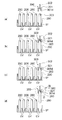
次に、本実施の形態の表面処理方法について説明する。図6、7は、保管部STにコンバイナ200を載置した状態を示す図であり、図6はコンバイナを長手方向に見た図であり、図7はコンバイナを面方向に見た図である。保管部STは、コンバイナ200を載置するために複数の溝状の保持部CVを平行に並べて有している。保管部STの高さは、コンバイナ200に接近する治具JG(不図示)の妨げにならないサイズとなっている。
Next, the surface treatment method of the present embodiment will be described. 6 and 7 are views showing a state in which the
まず不図示の金型を用いて、コンバイナ200を射出成形する。射出成形後のコンバイナ200は、図6,7に示すように、それぞれ直線溝203が上方側になるようにして例えば22〜26mmの間隔を空けて、保管部STの保持部CVによって仕分けられ、支えられることで起立するよう載置される。図6において理解しやすいように、保持部CVの両壁とコンバイナ200との間隔は広く描かれているが、実際はコンバイナ200が略鉛直方向に起立するように、その間隔は狭くなっている。
First, the
ここで、不図示の駆動機構を駆動させて、図5に示すガイドレールGRを、搬送すべきコンバイナ200の斜め上方(図7)に位置させる。このとき、図6(a)に示すように、治具300のフレーム部301の中央が、コンバイナ200の中心を通り且つ面に沿った仮想面上に位置するようになっており、短円筒軸301dは水平方向に突き出している。
Here, a drive mechanism (not shown) is driven to position the guide rail GR shown in FIG. 5 diagonally above the
次いで、図5に示すアクチュエータACを駆動して、図6(b)、7(b)に示すように、フレーム部301を下降させ、コンバイナ200の直線溝203の延長線上に、2つの短円筒軸301dが位置するようにする。尚、駆動に関しては、予め入力された3次元座標に向かうように治具300を制御しても良いし、不図示のカメラなどの撮像した画像から、コンバイナ200と治具300との相対位置を求めて制御を行っても良い。
Next, the actuator AC shown in FIG. 5 is driven to lower the
かかる状態から、図5に示すガイドレールGR(係合方向)に沿ってスライダSLを移動させ、図6(c)、7(c)に示すように、一方向からコンバイナ200に治具300を接近させ、更に直線溝203内に2つの短円筒軸301dを進入させる。丸軸部302がコンバイナ200の中央に到達した時点で、スライダSLの移動を停止させる。このとき、短円筒軸301dは直線溝203の係合位置に位置することとなる。係合位置に至るまで、治具300はコンバイナ200のいずれにも接触しないことが望ましい。
From this state, by moving the slider SL along the guide rails GR (engaging direction) shown in FIG. 5, FIG. 6 (c), the as shown in 7 (c), whereas
その後、図5に示すアクチュエータACを駆動して、図6(d)、7(d)に示すように、フレーム部301を上昇させる(鉛直上方向に移動させる)。すると、2つの短円筒軸301dが直線溝203の上側の壁に当接し、ここを介して上昇力をコンバイナ200に伝達するので、コンバイナ200は治具300と共に上昇することとなる。かかる状態で、直線溝203が水平になると好ましい。治具300はコンバイナ200を保持する為に把持部を有しないので、小型で簡素且つ安価な構成とできる。
Then, the actuator AC shown in FIG. 5 is driven to raise the frame portion 301 (moves vertically upward) as shown in FIGS. 6D and 7D. Then, the two short
更に、治具300に保持されたコンバイナ200は、ガイドレールGRに沿ってスライダSLを移動させることで、図示しないハードコート処理液が貯留された液槽上へと移動し、アクチュエータACの駆動によって下降されて、ハードコート処理液へと浸漬され、その後、液槽から引き上げられて乾燥されるようになっている。尚、コンバイナ200をハードコート処理液に浸漬する際に、治具300はハードコート処理液に浸さないようにするのが望ましい。処理後に、再び保管部STにコンバイナ200を戻した後には、治具300を上述とは逆に移動させることで、コンバイナ200から離脱させることができる。治具300が係合位置から離れ更にコンバイナ200から離脱するまで、コンバイナ200のいずれにも接触しないことが望ましい。
Further, by moving the slider SL along the guide rail GR, the
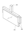
次に、比較例を参照して、本実施の形態の治具の効果について説明する。図8〜9は、比較例にかかる治具を用いてコンバイナを保持する状態を示す斜視図である。まず図8に示す治具JG1は、例えば点線位置と実線位置とで可動する可動アームAMを用いて、コンバイナCNの両端面を把持するものである。これによりコンバイナCNの面方向における治具JG1のはみ出し量が少なく、稼働スペース上有利である。また、可動アームAMを用いてコンバイナCNの端面を把持することで、コンバイナCNのふらつきを抑えて確実に保持することができる。 Next, the effect of the jig of this embodiment will be described with reference to a comparative example. 8 to 9 are perspective views showing a state in which the combiner is held by using the jig according to the comparative example. First, the jig JG1 shown in FIG. 8 holds both end surfaces of the combiner CN using, for example, a movable arm AM that is movable between a dotted line position and a solid line position. As a result, the amount of protrusion of the jig JG1 in the plane direction of the combiner CN is small, which is advantageous in terms of operating space. Further, by gripping the end surface of the combiner CN using the movable arm AM, it is possible to suppress the wobbling of the combiner CN and hold it reliably.
しかしながら、図8の治具JG1の場合、可動アームAMを駆動するアクチュエータを含む駆動機構が必要となって、治具JG1の大型化やコスト増を招く恐れがあり、可動アームAMを干渉なく駆動させる空間もコンバイナCNの周囲に必要となる。又、保持性を高めるために、可動アームAMの駆動力を増大させると、樹脂製であるコンバイナ200にストレスを与え,光学面の変形を招いたり、コンバイナ200に圧痕などが生じたりする恐れもある。
However, in the case of the jig JG1 of FIG. 8, a drive mechanism including an actuator for driving the movable arm AM is required, which may lead to an increase in the size and cost of the jig JG1, and the movable arm AM is driven without interference. A space for this is also required around the combiner CN. Further, if the driving force of the movable arm AM is increased in order to improve the holding property, stress may be applied to the
次に図9に示す治具JG2は、コンバイナCNを射出成形した後に生じるゲート部GTを用いて、コンバイナCNを保持するものである。ゲート部GTを保持することで、図8の治具JG1のようにコンバイナCNの側方にはみ出す可動アームは不要となり、治具JG2の小型化を図れる。 Next, the jig JG2 shown in FIG. 9 holds the combiner CN by using the gate portion GT formed after the combiner CN is injection-molded. By holding the gate portion GT, a movable arm protruding to the side of the combiner CN as in the jig JG1 in FIG. 8 is unnecessary, and the jig JG2 can be downsized.
しかしながら、図9に示す治具JG2の場合、仮にゲート部GTを把持する構成とすると駆動機構が必要であるし、或いはゲート部GTを引っかける構成であれば、コンバイナCNのふらつきが懸念される。更に、図9に示す治具JG2を用いるために、ハートコート処理までゲート部GTを残しておかなくてはならないが、ハートコート処理後にゲート部GTをカットすると、カット時の固定によりハードコート層が損傷したり、またカット時に飛散して光学面に付着した切粉の洗浄する工程が増えるなどの問題がある。 However, in the case of the jig JG2 shown in FIG. 9, if the gate portion GT is configured to be gripped, a drive mechanism is required, or if the configuration is such that the gate portion GT is hooked, there is a concern that the combiner CN may fluctuate. Further, since the jig JG2 shown in FIG. 9 is used, the gate portion GT must be left until the heart coat treatment. However, if the gate portion GT is cut after the heart coat treatment, the hard coat layer is fixed due to fixing at the time of cutting. However, there are problems such as damage to the surface, and an increase in the number of steps for cleaning the chips that are scattered during cutting and adhere to the optical surface.
更に図10に示す治具JG3は、水平方向に突き出した2つの突出部PRを設けており、これをコンバイナCNに形成した孔HLにそれぞれ挿通して、上方に引き上げることで保持を行うものである。治具JG3は可動機構を持たないため、安価に構成できるという点で有利である。 Further, the jig JG3 shown in FIG. 10 is provided with two projecting portions PR projecting in the horizontal direction, which are respectively inserted into the holes HL formed in the combiner CN and pulled upward to hold. is there. Since the jig JG3 does not have a movable mechanism, it is advantageous in that it can be inexpensively constructed.
しかるに、図10に示す治具JG3の場合、突出部PRを孔HLに挿通する為に、コンバイナCNの面方向(矢印方向)に治具JG3を変位させなくてはならず、従ってコンバイナCNの保管時に、隣接するコンバイナCNとの間隔をある程度確保しなくてはならず、大きな保管スペースが必要になるという問題がある。又、図10に示す治具JG3でコンバイナCNを保持しつつ、ハードコート処理液へと浸漬した際に、コンバイナCNが傾いてしまい適切な位置にハードコート層を形成できなかったり、或いはコンバイナCNの浮力で突出部PRが孔HLから外れてしまう恐れもある。以上の比較例に対して、本実施の形態では以下のような効果を得られる。 However, in the case of the jig JG3 shown in FIG. 10, in order to insert the protrusion PR into the hole HL, the jig JG3 must be displaced in the plane direction (arrow direction) of the combiner CN, and therefore the combiner CN At the time of storage, there is a problem in that a large storage space is required because a space between the adjacent combiner CN must be secured to some extent. Further, when the combiner CN is held by the jig JG3 shown in FIG. 10 and immersed in the hard coat treatment liquid, the combiner CN tilts and the hard coat layer cannot be formed at an appropriate position, or the combiner CN is not formed. There is a possibility that the protrusion PR may come off the hole HL due to the buoyancy. In contrast to the above comparative example, the following effects can be obtained in the present embodiment.
図11は、図6(d)の構成の矢印XIで示す部位を拡大して示す図である。コンバイナ200は、2つの短円筒軸301dと直線溝203の上側の壁との当接点のみで支持されているので、空調の風や振動等を受けることで容易に揺動する恐れがある。しかしながら、本実施の形態のコンバイナ200は、短円筒軸301dに対向して第2壁部301bを設けているので、図11の一点鎖線で示すように、支点P1(短円筒軸301dと直線溝203の上側の壁との当接点)回りに揺動したときに、コンバイナ200の投影部201以外の面における当接点(当接部)P2が第2壁部301bと当接し、それ以上の揺動が阻止されるようになっている。
FIG. 11 is an enlarged view of a portion indicated by an arrow XI in the configuration of FIG. 6D. Since the
これにより、治具300で保持されている際におけるコンバイナ200の揺動を、有効に抑制できる。同様に、治具300でコンバイナ200を保持しながらハードコート処理液に浸漬した際にも、コンバイナ200の姿勢を維持できるので、ハードコート処理液中でのコンバイナ200の外れを防止し、適切な位置までハードコート層を形成することができる。
As a result, swinging of the
図12は、変形例にかかる治具を示す図4と同様な図であり、図12(a)は、コンバイナを保持する治具の側面図であり、図12(b)は、図12(a)の治具をXIIB-XIIB線で切断して矢印方向に見た図である。本変形例においては、治具300は、2つの短円筒軸の代わりに、水平に延在するリブ(突起)301eを形成している。それ以外の構成は、上述した実施の形態と同様である。変形例を用いたコンバイナの保持態様について、以下に説明する。
12 is a view similar to FIG. 4 showing a jig according to a modified example, FIG. 12(a) is a side view of a jig for holding a combiner, and FIG. 12(b) is a side view of FIG. It is the figure which saw the jig of a) by the XIIB-XIIB line, and was seen in the arrow direction. In the present modification, the
治具300でコンバイナ200を保持する際に、図6(a)を参照して、治具300のフレーム部301の中央を、コンバイナ200の中心を通り且つ面に沿った仮想面上に位置させる。次いで、図6(b)、7(b)を参照して、フレーム部301を下降させると、コンバイナ200の直線溝203の延長線上に、リブ301eの中心線が位置するようにする。
When the
かかる状態から、図6(c)、7(c)を参照して、コンバイナ200に治具300を接近させ、更に直線溝203内にリブ301eを進入させる。その後、図6(d)、7(d)を参照して、フレーム部301を上昇させる。すると、リブ301eが直線溝203の上側の壁に当接し、ここを介して上昇力をコンバイナ200に伝達するので、コンバイナ200は治具300と共に上昇することとなる。
From this state, referring to FIGS. 6(c) and 7(c), the
図13は、別の実施の形態にかかるコンバイナ210の斜視図である。コンバイナ210は、図4に示す治具300を用いて保持するのに好適である。図13において、コンバイナ210は、上述した実施の形態と同様な形状の直線溝213と、直線溝213の上側の壁2カ所に形成された台形凹状の受け部213dとを形成している。それ以外の構成は、上述した実施の形態と同様である。
FIG. 13 is a perspective view of a
図14は、治具300を用いてコンバイナ210を把持した状態で,コンバイナ210の直線溝213付近を拡大して示す図であるが、丸軸部は省略している。図15は、図14(a)の構成をXV-XV線で切断して矢印方向に見た断面図である。
FIG. 14 is an enlarged view showing the vicinity of the
図15に示すように、受け部213dは、上方に向かうにつれて互いに接近する斜面213e、213fと底面213gとを有している。直線溝213と受け部213dは、コンバイナ210の射出成形時に金型を用いて同時に成形できる。
As shown in FIG. 15, the receiving
治具300でコンバイナ210を保持する際に、図6(a)を参照して、治具300のフレーム部301の中央を、コンバイナ210の中心を通り且つ面に沿った仮想面上に位置させる。次いで、図6(b)、7(b)を参照して、フレーム部301を下降させると、コンバイナ210の直線溝213の延長線上に、2つの短円筒軸301dが位置するようにする。
When the
かかる状態から、図6(c)、7(c)を参照して、コンバイナ210に治具300を接近させ、更に直線溝213内に短円筒軸301dを進入させ,係合位置である受け部213dの下方に位置させる。その後、図6(d)、7(d)を参照して、フレーム部301を上昇させる。すると、図14,15に示すように、短円筒軸301dがそれぞれ対応する受け部213d内へと進入する。このとき、テーパー状に傾いた斜面213e、213fが短円筒軸301dの進入を案内するようになっている。最終的には、短円筒軸301dは受け部213dの底面213gに当接することとなるので、かかる状態で治具300を上昇させることで、コンバイナ210を保持できる。
From this state, referring to FIGS. 6(c) and 7(c), the
ここで、底面213gは、直線溝213の延在方向(図15で左右方向)において受け部213dで最も短い距離の部位となる。このとき、短円筒軸301dの外径をφとしたときに、底面213gの長さが1.3φ〜1.8φの範囲内にあると、治具300の移動制御を簡易にできるので好ましい。
Here, the
又、図14(a)において、コンバイナ210の厚みをA,治具300の短円筒軸301dを形成した第1壁部301aと、短円筒軸301dに対向した第2壁部301bとの間隔をB,短円筒軸301dの第1壁部301aからの突き出し量をC,直線溝213の深さをDとしたときに、以下の式が成立すると好ましい。
B>A (1)
D>C (2)
C>B−A (3)
In addition, in FIG. 14A, the thickness of the
B>A (1)
D>C (2)
C>B-A (3)
(1)式が成立することで、図14(a)に示すように、治具300の第1壁部301aと第2壁部301bとの間にコンバイナ210を収容することができる。又、(2)式が成立することで、図14(c)に示すように、コンバイナ200が最大限第1壁部301a側に寄ったときにも、短円筒軸301dが直線溝213(及び受け部213d)に底付きしないようにできる。更に、(3)式が成立することで、図14(b)に示すように、コンバイナ200が最大限第2壁部301b側に寄ったときにも、短円筒軸301dが直線溝213(及び受け部213d)から抜け出すことがなく、コンバイナ210の落下を抑制することができる。
By satisfying the expression (1), the
図16〜18は、変形例にかかるコンバイナを示す斜視図であり、これらのコンバイナは、図4に示す治具300を用いて保持するのに好適である。図16の変形例において、コンバイナ220の直線溝223は途中で終端している。直線溝223の端部及び中間点からコンバイナ220の上端224に連通するようにして、連通溝223b、223cが設けられている。互いに直交する直線溝223及び連通溝223b、223cは、コンバイナ220の射出成形時に金型を用いて同時に成形できる。それ以外の構成は、上述した実施の形態と同様である。
16 to 18 are perspective views showing combiners according to modified examples, and these combiners are suitable to be held by using the
治具300でコンバイナ220を保持する際、治具300の短円筒軸301dを、コンバイナ220の上方で連通溝223b、223cの延長線上に位置させる。次いで、第1の係合方向に治具300を下降させると、コンバイナ220の連通溝223b、223cに、2つの短円筒軸301dが進入する。
When the
短円筒軸301dが直線溝223内に到達した時点で、治具300を直線溝223の延在方向(第2の係合方向)に移動させると、短円筒軸301dが直線溝223内へと進入する。その後、所望の係合位置にて鉛直上方向に治具300を上昇させると、短円筒軸301dが直線溝223の上側の壁に当接するので、コンバイナ220を保持できる。
When the
次に図17の変形例において、コンバイナ230は、図3に示す実施の形態と同様な形状の直線溝233を有しており、更に直線溝233からコンバイナ230の上端234に連通するようにして、2つの連通溝233b、233cが設けられている。互いに直交する直線溝233及び連通溝233b、233cは、コンバイナ230の射出成形時に金型を用いて同時に成形できる。それ以外の構成は、上述した実施の形態と同様である。
Next, in the modification of FIG. 17, the
治具300でコンバイナ230を保持する際、治具300の短円筒軸301dを、コンバイナ230の上方で連通溝233b、233cの延長線上に位置させる。次いで、第1の係合方向に治具300を下降させると、コンバイナ230の連通溝233b、233cに、2つの短円筒軸301dが進入する。
When the
短円筒軸301dが直線溝233内に到達した時点で、治具300を直線溝233の延在方向(第2の係合方向)に移動させると、短円筒軸301dが直線溝233内へと進入する。その後、所望の係合位置にて鉛直上方向に治具300を上昇させると、短円筒軸301dが直線溝233の上側の壁に当接するので、コンバイナ230を保持できる。
When the
更に図18の変形例において、コンバイナ240は直線溝を有しておらず、その代わりにコンバイナ240の上端244から下方に向かい且つ側方に向かうL字状の溝243a、243bを設けている。直角L字状の溝243a、243bは、コンバイナ240の射出成形時に金型を用いて同時に成形できる。それ以外の構成は、上述した実施の形態と同様である。
Further, in the modification of FIG. 18, the
治具300でコンバイナ240を保持する際、治具300の短円筒軸301dを、コンバイナ240の上方で溝243a、243bの延長線上に位置させる。次いで、第1の係合方向に治具300を下降させると、コンバイナ240のL字状の溝243a、243bに、2つの短円筒軸301dが進入する。
When the
短円筒軸301dがL字状の溝243a、243bの角に到達した時点で、治具300を側方(第2の係合方向)へと移動させると、短円筒軸301dがL字状の溝243a、243bの奥へと進入する。その後、所望の係合位置にて鉛直上方向に治具300を上昇させると、短円筒軸301dがL字状の溝243a、243bの上側の壁に当接するので、コンバイナ240を保持できる。
When the short
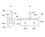
図19は、別な実施の形態にかかるコンバイナ250の斜視図であり、図20は、コンバイナ250を保持するのに好適な治具350を示す図であって、図20(a)は、コンバイナを保持する治具の側面図であり、図20(b)は、図20(a)の治具をXX-XX線で切断して矢印方向に見た図である。
FIG. 19 is a perspective view of a
図20において、丸軸部352に連結されたフレーム部351は、それぞれ矩形板状の第1壁部351a及び第2壁部351bと、第1壁部351a及び第2壁部351bの上端を互いに連結する上壁部351cとを有し、更に第1壁部351aと第2壁部351bとの間を架橋するように、2つの円筒軸(突起)351dが間隔を開けて配置されている。本実施の形態では、第1壁部351aと第2壁部351bが抑制部を構成する。それ以外の構成は、上述した実施の形態と同様である。
In FIG. 20, the frame portion 351 connected to the
図19において、コンバイナ250は、その上端254から下方に向かい且つ側方に向かうL字状の切欠253a、253bを設けている。切欠253a、253bは、投影部251の面に交差する方向に貫通している溝ということができる。直角L字状の切欠253a、253bは、コンバイナ250の射出成形時に金型を用いて同時に成形できる。それ以外の構成は、上述した実施の形態と同様である。
In FIG. 19, the
治具350でコンバイナ250を保持する際、治具350の円筒軸351dを、コンバイナ250の上方で切欠253a、253bの延長線上に位置させる。次いで、第1の係合方向に治具350を下降させると、コンバイナ250の切欠253a、253bに、2つの円筒軸351dが進入する。
When the
円筒軸351dが切欠253a、253bの角に到達した時点で、治具350を側方(第2の係合方向)へと移動させると、円筒軸351dが切欠253a、253bの奥へと進入する。その後、所望の係合位置にて鉛直上方向に治具350を上昇させると、円筒軸351dが切欠253a、253bの上側の壁に当接するので、コンバイナ250を保持できる。
When the
図21は、別な実施の形態にかかるコンバイナ260の斜視図であり、図22は、コンバイナ260を保持するのに好適な治具360を示す斜視図である。図21において、コンバイナ260は溝を設けておらず、その代わりに2つの円筒軸263aを、面に直角に間隔を開けて配置している。本実施の形態では、コンバイナ260側に部材係合部としての突起を設け、治具360側に突起に係合する治具係合部としての溝を設けたものである。
21 is a perspective view of a
図22に示す治具360において、丸軸部362に連結されたフレーム部361は、それぞれ矩形板状の第1壁部361a及び第2壁部361bと、第1壁部361a及び第2壁部361bの上端を互いに連結する上壁部361cとを有している。第1壁部361aは、軸を設けておらず、その代わりに直線溝361dと、直線溝361dの下側の壁2カ所に形成された台形凹状の受け部361e、361fとを形成している。受け部361e、361fは、図13〜15に示す例と天地を逆にして同様な形状である。それ以外の構成は、上述した実施の形態と同様である。
In the
治具360でコンバイナ260を保持する際に、図6(a)を参照して、治具360のフレーム部361の中央を、コンバイナ260の中心を通り且つ面に沿った延長面上に位置させる。次いで、図6(b)、7(b)を参照して、フレーム部361を下降させると、第1壁部361aの直線溝361dの延長線上に、2つの円筒軸263aが位置するようにする。
When the
かかる状態から、図6(c)、7(c)を参照して、コンバイナ260に治具360を接近させ、更に直線溝361d内に円筒軸263aを進入させる。その後、図6(d)、7(d)を参照して、フレーム部361を上昇させる。すると、円筒軸263aがそれぞれ対応する受け部361e、361f内へと進入する。最終的には、円筒軸263aは受け部361e、361fの底面に当接することとなる。かかる状態で、治具360を上昇させることで、コンバイナ260を保持できる。
From this state, referring to FIGS. 6C and 7C, the
図23は、変形例にかかるコンバイナを治具により保持する直前の状態を示した図5と同様な図であるが、保管部は省略している。変形例のコンバイナ270は、図3に示すコンバイナに対して湾曲している点が異なっており、これに応じてガイドレールGRを湾曲させている。これにより、治具300はコンバイナ270に接近する際に、コンバイナ270の曲率に対応する円弧を描きながら変位することとなる。これにより、フレーム部301内にコンバイナ270を容易に収容することができる。尚、治具300のフレーム部301自体を、コンバイナ270の曲率に合わせて湾曲させても良い。
FIG. 23 is a view similar to FIG. 5 showing a state immediately before the combiner according to the modified example is held by a jig, but the storage unit is omitted. The
本発明は、明細書に記載の実施例に限定されるものではなく、他の実施例・変形例を含むことは、本明細書に記載された実施例や思想から本分野の当業者にとって明らかである。例えば、本発明の表示部材及びヘッドアップディスプレイ装置は、自動車に限らず、飛行機や重機にも用いることが出来る。処理液とはハードコート処理液に限られず、防汚コート、反射防止コートなど種々の層を形成する為の処理液を含む。表示部材の形状は、矩形に限らず、丸形、多角形、台形など種々の形状を含んでいて良い。短円筒軸は2本に限らず3本以上設けても良い。 The present invention is not limited to the embodiments described in the specification, and it is apparent to those skilled in the art from the embodiments and ideas described in the present specification that other embodiments and modifications are included. Is. For example, the display member and head-up display device of the present invention can be used not only for automobiles but also for airplanes and heavy equipment. The treatment liquid is not limited to the hard coat treatment liquid, but includes treatment liquids for forming various layers such as an antifouling coat and an antireflection coat. The shape of the display member is not limited to a rectangle and may include various shapes such as a round shape, a polygonal shape, and a trapezoidal shape. The short cylindrical shaft is not limited to two and may be three or more.
100 描画ユニット
110 描画デバイス
111 液晶表示パネル
120 凹面鏡
130 ハウジング
200、210、220、230、240,250,260、270 コンバイナ
201 投影部
202 取付部
203、213、223,233 直線溝
213d 受け部
213e、213f 斜面
223b、233b 連通溝
224、234、244、254 上端
243a、243b 溝
253a 切欠
263a 円筒軸
300、350,360 治具
301、351、361 フレーム部
301a,351a,361a 第1壁部
301b、351b、361b 第2壁部
301c、351c、361c 上壁部
301d、351d 短円筒軸
301e リブ
301g 底面
302,352、362 丸軸部
361d 直線溝
361e 受け部
AC アクチュエータ
AM 可動アーム
BKT ブラケット
BT ボルト
CV 保持部
DB ダッシュボード
DR ドライバー
FK 鈎部
GR ガイドレール
GT ゲート部
RL ガイドレール
SL スライダ
ST 保管部
VH 車体
100
Claims (16)
前記冶具は、前記冶具係合部に対向する壁部を有し、
前記治具を前記表示部材に沿った係合方向に移動させることで、前記治具係合部を前記部材係合部に対して係合位置へと進入させ、
前記治具を前記係合方向とは異なる鉛直上方向に移動させることで、前記係合位置にて当接した前記治具係合部と前記部材係合部との間で伝達される力により前記表示部材を支持し、
前記表示部材の表面処理中に、前記表示部材を保持した前記治具により、前記係合位置を支点とする前記表示部材の傾きを前記壁部において抑制する表示部材の表面処理方法。 A surface treatment method for a display member, which holds a jig by engaging a jig engaging portion of a jig with a member engaging portion of a plate-shaped display member while performing a predetermined treatment on the display member. And
The jig has a wall portion facing the jig engaging portion,
By moving the jig in the engaging direction along the display member, the jig engaging portion is advanced to the engaging position with respect to the member engaging portion,
By moving the jig in a vertically upward direction different from the engaging direction, the force transmitted between the jig engaging portion and the member engaging portion that abut at the engaging position causes Supporting the display member,
A surface treatment method for a display member, wherein during the surface treatment of the display member, the jig holding the display member suppresses the inclination of the display member around the engagement position as a fulcrum on the wall portion .
前記部材係合部は、前記光学面と同一面内であってその一端側に設けられ、
前記冶具は、前記冶具係合部に対向する壁部を有し、前記抑制部は前記壁部から構成され、
前記表示部材に対して前記治具を前記光学面に沿って係合方向に移動させたとき、前記治具係合部が前記部材係合部に対して係合位置へと進入するようになっており、
前記表示部材に対して前記治具を前記係合方向とは異なる鉛直上方向に移動させたとき、前記係合位置にて当接した前記治具係合部と前記部材係合部との間で伝達される力により前記表示部材を支持可能となっており、
前記治具により保持した前記表示部材を処理する際に、前記抑制部を構成する前記壁部と前記当接部とが当接することにより、前記係合位置を支点とする前記表示部材の傾きが抑制されるようになっている表示部材。 A display member having an optical surface that is subjected to a predetermined process, a member engaging portion that can engage with a jig engaging portion of a jig, and an abutting portion that can abut against the jig restraining portion. There
The member engaging portion is provided on the one end side in the same plane as the optical surface,
The jig has a wall portion facing the jig engaging portion, the suppressing portion is composed of the wall portion,
When the jig is moved in the engaging direction along the optical surface with respect to the display member, the jig engaging portion enters the engaging position with respect to the member engaging portion. And
Between the jig engaging portion and the member engaging portion that abut at the engaging position when the jig is moved in a vertically upward direction different from the engaging direction with respect to the display member. It is possible to support the display member by the force transmitted by
When the display member held by the jig is processed, the inclination of the display member with the engaging position as a fulcrum is caused by the contact between the wall portion and the contact portion that configure the suppressing portion. A display member adapted to be suppressed.
前記部材係合部は、前記治具係合部が前記部材係合部の上端から進入し、前記係合位置で前記表示部材を支持可能となっている形状を有し、
前記治具係合部は突起であり、前記部材係合部は、前記治具に保持された状態で、鉛直方向及び水平方向に延在する溝である請求項2に記載の表示部材。 The engagement direction is a vertically upward direction and a vertical orthogonal direction,
The member engaging portion has a shape such that the jig engaging portion enters from the upper end of the member engaging portion and can support the display member at the engaging position.
The display member according to claim 2, wherein the jig engaging portion is a protrusion, and the member engaging portion is a groove extending in the vertical direction and the horizontal direction while being held by the jig .
前記冶具は、前記冶具係合部に対向する壁部を有し、前記抑制部は前記壁部から構成され、
前記治具を前記表示部材に沿った係合方向に移動させたとき、前記治具係合部が前記部材係合部に対して係合位置へと進入するようになっており、
前記治具を前記係合方向とは異なる鉛直上方向に移動させることで、前記係合位置にて当接した前記治具係合部と前記部材係合部との間で伝達される力により前記表示部材を支持するようになっており、
前記治具により保持した前記表示部材を処理する際に、前記抑制部を構成する前記壁部により、前記係合位置を支点とする前記表示部材の傾きを抑制するようになっている治具を備える表示部材の表面処理装置。 Surface of display member including jig having jig engaging portion engageable with member engaging portion of plate-shaped display member and restraining portion provided at a position facing the jig engaging portion A processing device ,
The jig has a wall portion facing the jig engaging portion, the suppressing portion is composed of the wall portion,
When the jig is moved in the engagement direction along the display member, the jig engagement portion is adapted to enter the engagement position with respect to the member engagement portion,
By moving the jig in a vertically upward direction different from the engaging direction, the force transmitted between the jig engaging portion and the member engaging portion that abut at the engaging position causes It is designed to support the display member,
When processing the display member which is held by the jig, by the wall portion constituting the suppressing portion, the to and jig adapted to suppress the inclination of the display member to pivot said engaging position A surface treatment device for a display member .
B>A (1)
D>C (2)
C>B−A (3) The jig has a first wall portion having the protrusion and a second wall portion facing the protrusion, the plate thickness of the display member is A, the first wall portion and the second wall portion. 16. The surface treatment device for a display member, comprising the jig according to claim 15, wherein the following formula is established, where B is the interval between the protrusions, C is the protrusion amount of the protrusion, and D is the depth of the groove.
B>A (1)
D>C (2)
C>B-A (3)
Priority Applications (1)
| Application Number | Priority Date | Filing Date | Title |
|---|---|---|---|
| JP2016119644A JP6702009B2 (en) | 2016-06-16 | 2016-06-16 | Display member surface treatment method, display member and display member surface treatment apparatus |
Applications Claiming Priority (1)
| Application Number | Priority Date | Filing Date | Title |
|---|---|---|---|
| JP2016119644A JP6702009B2 (en) | 2016-06-16 | 2016-06-16 | Display member surface treatment method, display member and display member surface treatment apparatus |
Publications (2)
| Publication Number | Publication Date |
|---|---|
| JP2017223856A JP2017223856A (en) | 2017-12-21 |
| JP6702009B2 true JP6702009B2 (en) | 2020-05-27 |
Family
ID=60685982
Family Applications (1)
| Application Number | Title | Priority Date | Filing Date |
|---|---|---|---|
| JP2016119644A Expired - Fee Related JP6702009B2 (en) | 2016-06-16 | 2016-06-16 | Display member surface treatment method, display member and display member surface treatment apparatus |
Country Status (1)
| Country | Link |
|---|---|
| JP (1) | JP6702009B2 (en) |
Family Cites Families (6)
| Publication number | Priority date | Publication date | Assignee | Title |
|---|---|---|---|---|
| US5718849A (en) * | 1995-09-25 | 1998-02-17 | Galic Maus Ventures | Method and apparatus for injection-compression molding & ejecting paired thermoplastic spectacle lens suited for fully automated dip hardcoating |
| JP3320302B2 (en) * | 1996-04-10 | 2002-09-03 | ホーヤ株式会社 | Injection compression molding method for lenses |
| JP2000241886A (en) * | 1999-02-19 | 2000-09-08 | Mitsubishi Electric Corp | Rear projection type video display |
| US20030077396A1 (en) * | 2001-10-23 | 2003-04-24 | Lecompte Robert S. | Dip coating system |
| JP5887933B2 (en) * | 2011-12-28 | 2016-03-16 | 日本精機株式会社 | Head-up display device |
| JP6123229B2 (en) * | 2012-10-30 | 2017-05-10 | コニカミノルタ株式会社 | Combiner manufacturing method and combiner |
-
2016
- 2016-06-16 JP JP2016119644A patent/JP6702009B2/en not_active Expired - Fee Related
Also Published As
| Publication number | Publication date |
|---|---|
| JP2017223856A (en) | 2017-12-21 |
Similar Documents
| Publication | Publication Date | Title |
|---|---|---|
| JP6123229B2 (en) | Combiner manufacturing method and combiner | |
| US20170052562A1 (en) | Image display apparatus | |
| CN104428697B (en) | Micro mirror array, its preparation method and the optical element for this micro mirror array | |
| CN105033465A (en) | Laser internal-engraving method and device for rough-surface transparent material | |
| CN210941587U (en) | Vehicle-mounted HUD screen display device based on mobile terminal | |
| WO2019201061A1 (en) | Mist removing device and control method therefor, and mist removing system and control element | |
| JP6702009B2 (en) | Display member surface treatment method, display member and display member surface treatment apparatus | |
| JP2013068735A (en) | Camera lens wiper | |
| JP5887933B2 (en) | Head-up display device | |
| EP2386900A1 (en) | Lens holding jig and method of manufacturing lens base material using same | |
| CN114653510B (en) | Automatic ink coating method and device for side edges of AR (augmented reality) glasses lenses and related equipment | |
| EP3543764A1 (en) | Display member, head-up display device, and jig | |
| KR20130036706A (en) | Scribe method for glass substrate | |
| WO2018117122A1 (en) | Plate with printed layer, cover member, and display device | |
| WO2022232819A1 (en) | Imprint lithography process and methods on curved surfaces | |
| JPWO2018092636A1 (en) | Display member, head-up display device, and jig | |
| KR102748363B1 (en) | Device for assembling an aspheric mirror for head up display | |
| JP2010022883A (en) | Paste applicator | |
| WO2013140888A1 (en) | Component positioning device, and method for manufacturing sheet in which plurality of components for which positioning is completed are transferred/fixed onto sheet surface | |
| JP7000901B2 (en) | Image display device and its manufacturing method | |
| CN104708763B (en) | Mirror manufacturing system and lens manufacturing method | |
| CN210706124U (en) | Attached tool of better protection film of pad pasting effect | |
| CN222225360U (en) | Optical lens transfer tool | |
| CN116234654B (en) | Method for producing synthetic resin film | |
| KR102748364B1 (en) | Device for assembling an aspheric mirror for head up display |
Legal Events
| Date | Code | Title | Description |
|---|---|---|---|
| A621 | Written request for application examination |
Free format text: JAPANESE INTERMEDIATE CODE: A621 Effective date: 20181225 |
|
| A977 | Report on retrieval |
Free format text: JAPANESE INTERMEDIATE CODE: A971007 Effective date: 20191023 |
|
| A131 | Notification of reasons for refusal |
Free format text: JAPANESE INTERMEDIATE CODE: A131 Effective date: 20191029 |
|
| A521 | Request for written amendment filed |
Free format text: JAPANESE INTERMEDIATE CODE: A523 Effective date: 20191227 |
|
| TRDD | Decision of grant or rejection written | ||
| A01 | Written decision to grant a patent or to grant a registration (utility model) |
Free format text: JAPANESE INTERMEDIATE CODE: A01 Effective date: 20200407 |
|
| A61 | First payment of annual fees (during grant procedure) |
Free format text: JAPANESE INTERMEDIATE CODE: A61 Effective date: 20200420 |
|
| R150 | Certificate of patent or registration of utility model |
Ref document number: 6702009 Country of ref document: JP Free format text: JAPANESE INTERMEDIATE CODE: R150 |
|
| LAPS | Cancellation because of no payment of annual fees |