JP6702107B2 - Lane departure suppression device - Google Patents
Lane departure suppression device Download PDFInfo
- Publication number
- JP6702107B2 JP6702107B2 JP2016177674A JP2016177674A JP6702107B2 JP 6702107 B2 JP6702107 B2 JP 6702107B2 JP 2016177674 A JP2016177674 A JP 2016177674A JP 2016177674 A JP2016177674 A JP 2016177674A JP 6702107 B2 JP6702107 B2 JP 6702107B2
- Authority
- JP
- Japan
- Prior art keywords
- lane
- vehicle
- reflection coefficient
- suppression device
- reference line
- Prior art date
- Legal status (The legal status is an assumption and is not a legal conclusion. Google has not performed a legal analysis and makes no representation as to the accuracy of the status listed.)
- Active
Links
Images





Landscapes
- Steering Control In Accordance With Driving Conditions (AREA)
- Control Of Driving Devices And Active Controlling Of Vehicle (AREA)
- Traffic Control Systems (AREA)
Description
本発明は、車線逸脱抑制装置に関する。 The present invention relates to a lane departure suppression device.
車線の逸脱を防止する技術として次の技術が知られている。
コントローラは、自車線に対する自車両の横変位とその変化量に基づいて自車両が自車線から逸脱するまでの予測時間を算出し、逸脱予測時間に基づいて将来的な逸脱のリスクを表す逸脱リスク度を算出し、そして、逸脱リスク度に基づいてアクセルペダル反力と操舵反力をそれぞれ制御するとともに、自車線の逸脱を回避する方向に、左右輪の制動力差によってヨーモーメントを発生させ、これにより、自車線からの逸脱リスクを運転者に伝達しながら逸脱防止制御を行う技術が知られている(下記、特許文献1参照)。
The following techniques are known as techniques for preventing deviation from the lane.
The controller calculates the estimated time until the vehicle departs from the own lane based on the lateral displacement of the own vehicle with respect to the own lane and the amount of change, and the deviation risk that represents the risk of future deviation based on the estimated deviation time. Degree, and controls the accelerator pedal reaction force and the steering reaction force based on the deviation risk degree, and generates a yaw moment by the braking force difference between the left and right wheels in the direction to avoid deviation from the own lane, Accordingly, there is known a technique for performing deviation prevention control while transmitting the deviation risk from the own lane to the driver (see
ところで、車両が走行する道路の種類や走行場所によって車線の状態は異なる。例えば、車線幅が太い道路や細い道路のように車線幅が異なる場合もあり、道路の形状が直線状の場合やカーブしている場合もある。 By the way, the state of the lane differs depending on the type of road on which the vehicle travels and the traveling location. For example, the lane width may be different such as a road with a wide lane width or a narrow road, and the shape of the road may be linear or curved.
このように道路の車線幅や形状等の車線の状態によっては、従来の車線逸脱制御では対応できず、車両が車線を逸脱してしまう場合も考えられる。このため、車線の状態に応じて、車両の車線逸脱を抑制制御する技術が求められている。 As described above, depending on the lane condition such as the lane width and the shape of the road, the conventional lane departure control cannot be applied and the vehicle may depart from the lane. Therefore, there is a demand for a technique for suppressing and controlling the lane departure of the vehicle in accordance with the lane condition.
本発明は、上記事情に鑑みてなされたものであり、車線の状態に応じて適切な車線逸脱抑制を実行することができる車線逸脱抑制装置を提供することを目的とする。 The present invention has been made in view of the above circumstances, and an object of the present invention is to provide a lane departure restraint device that can appropriately perform lane departure restraint according to the state of a lane.
本発明の車両の車線逸脱を抑制する車線逸脱抑制装置は、車線の状態を検出する車線状態検出手段と、前記車線状態検出手段により検出した前記車線の状態と、前記車線の状態に応じて前記車線の区画線より車線中央側に作成される基準線と、前記車両の所定時間後の推定位置とに基づいて、前記車両が走行車線を逸脱するか否かを判定する判定手段と、前記判定手段により前記車両が前記走行車線を逸脱すると判定された場合、前記車線を逸脱する逸脱量に応じて操舵量を決定するための反映係数を設定し、この設定した反映係数と、前記基準線に対する目標操舵角とに基づいて操舵量を演算する演算手段と、前記演算手段により演算した操舵量に基づいて前記車両の旋回方向の移動を抑制する抑制手段と、を備えることを特徴とする。 A lane departure suppressing device for suppressing a lane departure of a vehicle of the present invention is a lane condition detecting means for detecting a lane condition, a lane condition detected by the lane condition detecting means, and a lane condition according to the lane condition. Determination means for determining whether or not the vehicle deviates from the traveling lane based on a reference line created on the lane center side of the lane marking and an estimated position of the vehicle after a predetermined time, and the determination When it is determined by the means that the vehicle deviates from the traveling lane, a reflection coefficient for determining the steering amount according to the deviation amount deviating from the lane is set, and the set reflection coefficient and the reference line are set. a calculating means for calculating a steering amount based on the target steering steering angle, characterized in that it comprises a suppression means for suppressing movement of the turning direction of the vehicle based on the calculated steering amount by the calculating means.
このように構成すると、車線逸脱抑制装置は、車線の状態に応じて適切な車線逸脱抑制を実行することができる。 With such a configuration, the lane departure restraint device can appropriately execute the lane departure restraint according to the state of the lane.
また、前記基準線は、前記車線の車線幅、及び前記車線の曲率のいずれかに応じて作成されても良い。このとき、前記基準線は、前記車線幅が狭いほど前記車線に寄せて設定されても良い。また、前記曲率が大きいほど、前記基準線は前記車線に寄せて設定されても良い。これにより、車線幅が狭いときに、又はカーブ走行時に車線逸脱抑制制御が及ばない幅を広く確保することができるため、不要な制御介入を抑制して煩わしさを低減させることができる。 Further, the reference line may be created according to either the lane width of the lane or the curvature of the lane. At this time, the reference line may be set closer to the lane as the lane width is narrower. The reference line may be set closer to the lane as the curvature is larger. As a result, when the lane width is narrow or the vehicle is traveling on a curve, it is possible to secure a wide range that the lane departure suppression control does not reach, so that it is possible to suppress unnecessary control intervention and reduce annoyance.
また、車線逸脱抑制装置は、前方注視2次予測モデルを用いて前記車両の位置を推定する位置推定手段を備え、前記逸脱量は、前記位置推定手段により推定される推定位置と、前記基準線との距離としても良い。 Further, the lane departure suppression apparatus includes position estimation means for estimating the position of the vehicle by using a forward gaze quadratic prediction model, and the deviation amount is the estimated position estimated by the position estimation means and the reference line. It may be a distance from.
このように構成すると、車両の旋回運動を考慮した推定位置になり、車両の推定位置の精度を向上させることができる。 According to this structure, the estimated position takes into consideration the turning motion of the vehicle, and the accuracy of the estimated position of the vehicle can be improved.
さらに、車線逸脱抑制装置は、前記車両の走行環境を取得する取得手段と、前記取得手段により取得する前記走行環境に基づいて、前記抑制手段を実行するか否かを決定する決定手段と、を備えても良い。 Further, the lane departure suppression apparatus includes an acquisition unit that acquires a traveling environment of the vehicle, and a determination unit that determines whether or not to execute the suppression unit, based on the traveling environment acquired by the acquisition unit. You may prepare.
これにより、車両逸脱抑制機能をOFFした方が良い走行環境では、車線逸脱抑制装置は車両逸脱抑制機能をOFFすることができるため、不要な制御介入や誤作動を抑制させることができる。 As a result, in a traveling environment in which it is better to turn off the vehicle departure restraint function, the lane departure restraint device can turn off the vehicle departure restraint function, and thus unnecessary control intervention and malfunction can be restrained.
さらに、車線逸脱抑制装置は、前記反映係数を決定するグラフを複数記憶する記憶手段を備え、前記設定手段は、前記取得手段により取得する走行環境に応じて複数の前記グラフから1つを選択し、前記反映係数を設定しても良い。 Furthermore, the lane departure suppression apparatus includes a storage unit that stores a plurality of graphs that determine the reflection coefficient, and the setting unit selects one from the plurality of graphs according to the traveling environment acquired by the acquisition unit. The reflection coefficient may be set.
これにより、複数のグラフから車線幅や走行環境に適したグラフを選択して、反映係数を設定することができるため、より適した反映係数を設定することできる。 Accordingly, a graph suitable for the lane width and the traveling environment can be selected from the plurality of graphs and the reflection coefficient can be set, so that a more suitable reflection coefficient can be set.
本発明によると、車線の状態に応じて適切な車線逸脱抑制を実行することができる車線逸脱抑制装置を提供できる。 According to the present invention, it is possible to provide a lane departure suppression device capable of executing appropriate lane departure suppression according to the state of the lane.
以下、本発明の実施の形態について図面を参照しながら説明する。
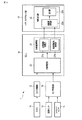
図1は、本発明の車線逸脱抑制装置が適用される車両1の概略的な構成の一例を示す図である。
Hereinafter, embodiments of the present invention will be described with reference to the drawings.
FIG. 1 is a diagram showing an example of a schematic configuration of a
図1に示すように、車両1は、カメラ11、カメラ制御部12、車輪速センサ13、ヨーレートセンサ14、センサ制御部15、ECU(Electronic Control Unit)16、及びパワーステアリング部17を備えている。ECU16は、逸脱判定部20、及び反映係数演算部21a、目標操舵角演算部21bを有する制御量演算部21を含み、パワーステアリング部17は、操舵量演算部22a、出力部22bを有する制御出力部22を含んでいる。なお、車両1は、車両としての機能を実現するための他の構成も備えているが、これらの構成については、図示及び説明を省略する。
As shown in FIG. 1, the
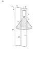
カメラ11は、例えば、車両1の前側に配置され、車両1の前側の所定距離下側のエリアを撮影し、この撮影した画像データをカメラ制御部12に出力する。図2は、カメラ11の撮影エリアAの一例を示す図である。図2に示すように、道路Rには、3つの区画線、すなわち、右区画線RL、中央区画線ML、右区画線RLが設けられており、中央区画線MLと左区画線LLとで区画される左側走行車線R1と、右区画線RLと中央区画線MLとで区画される右側走行車線R2とが構成されている。図2において、車両1は道路Rの左側走行車線R1を走行している状態を示している。カメラ11は、車両1の前方下側方向の撮影エリアAを撮影している。撮影エリアAは、少なくとも中央区画線ML及び左区画線LLを含む範囲を撮影可能になっている。なお、カメラ11の撮影エリアAは、道路Rの幅方向全体、つまり、右区画線RL、中央区画線ML、及び左区画線LLを撮影可能なように構成しても良い。
The
カメラ制御部12は、カメラ11から入力される画像データに対して、画像解析を行い、撮影エリアA内に含まれる中央区画線ML、左区画線LLの位置を特定し、さらに中央区画線MLと左区画線LLとの間における車両1の道路Rの幅方向の位置を特定する。カメラ制御部12は、これらの特定した情報をECU16に出力する。
The
車輪速センサ13は、車軸(図示省略)近傍に配置され、車軸の回転数を検出する。車速センサ13は、検出した回転数をセンサ制御部15に出力する。ヨーレートセンサ14は、車両1のヨーレート(旋回方向への回転角の変化速度)を検出する。ヨーレートセンサ14は、検出したヨーレートをセンサ制御部15に出力する。
The
センサ制御部15は、車輪速センサ13から入力される回転数に基づいて、車両1の車速を算出すると共に、算出した車速、及びヨーレートセンサ14から入力されるヨーレートをECU16に出力する。
The
ECU16は、車両1を総合的に制御する。例えば、車両1の車線逸脱を抑制する車線逸脱抑制制御を実行する。車線逸脱抑制制御は、ECU16に含まれる逸脱判定部20、制御量演算部21、及び制御出力部22が実行する。
The ECU 16 comprehensively controls the
逸脱判定部20は、車線の状態に応じて車線の区画線より車線中央側に作成される基準線と、車両1の所定時間後の推定位置とに基づいて、車両1が左走行車線R1を逸脱するか否かを判定する。
The
制御量演算部21は、車両1が左側走行車線R1を逸脱すると判定した場合、基準線と推定位置との距離(逸脱量)に応じて操舵量を決定するための反映係数を設定し、基準線DL1に対する目標操舵角を演算する。なお、車線逸脱抑制制御の詳細は、後述する。
When the control
反映計数演算部21aは、逸脱量に基づく反映係数を演算する。例えば、反映係数演算部21aは、車両1が左走行車線R1を逸脱する逸脱量に基づく反映係数を演算する。演算された反映係数は、反映係数演算部21bからパワーステアリング部17に出力される。
The
反映係数演算部21aは、操舵量を調整する処理に用いられる反映係数のグラフを記憶しており、この記憶しているグラフを用いて反映係数を演算する。図3は、反映係数のグラフの一例を説明するための図である。図3に示すように、反映係数のグラフg1は、逸脱量に応じて大きくなるように線形に設定されている。ここで、逸脱量は、車両1が左側走行車線R1を逸脱する量であり、詳細については後述する。
The
目標操舵角演算部21bは、逸脱量に基づく目標操舵角を演算する。演算された目標操舵角は、目標操舵角演算部21bからパワーステアリング部17に出力される。
The target steering
パワーステアリング部17は、ドライバの操舵を補助する装置である。パワーステアリング部は、制御量演算部21から入力される演算された反映係数、及び目標操舵角に基づいてドライバの操舵する力を調整する。
The
制御出力部22は、パワーステアリング部17の操舵力を調整する処理を実行する。
操作量演算部22aは、反映係数演算部21から入力される反映係数、及び目標操舵角演算部21bから入力される目標操舵角より操舵量を演算する。出力部22bは、操舵量を力(ニュートン)に変換する。制御出力部22は、この変換された力に基づいて操舵力を調整する。
The
The operation
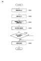
次に、車線逸脱抑制制御について説明する。図4は、ECU16、パワーステアリング部17が実行する車線逸脱抑制処理の一例を示すフローチャートである。なお、この処理は車両1の走行中において、常時実行される。
Next, the lane departure suppression control will be described. FIG. 4 is a flowchart showing an example of a lane departure suppression process executed by the
図4に示すように、ECU16は、車両1の走行環境を読み込む(ST101:取得手段)。ECU16は、カメラ制御部12から中央区画線ML、左区画線LL、及び車両1の位置をそれぞれ取得すると共に、センサ制御部15から車速、及びヨーレートを取得する。
As shown in FIG. 4, the
次に、ECU16は、車線逸脱抑制機能が有効か否かを判定する(ST102)。ECU16は、例えば、中央区画線ML、及び左区画線LLの位置が正確に認識されているか否かに基づいて、車線逸脱抑制機能が有効であるか否かを判定する。例えば、天候状態が悪いとき(例えば、降雨又は降雪が生じているとき)は、中央区画線ML、及び左区画線LLを正確に認識することが難しく、誤って認識された中央区画線ML、及び左区画線LLの位置に基づいて車線逸脱抑制機能が実行され、車線逸脱抑制機能が正確に動作しない場合が想定される。よって、このような場合には、車線逸脱抑制機能を無効にすることが望ましいため、本実施形態においては車線逸脱抑制機能をOFFする。これにより、車両逸脱抑制機能をOFFした方が良い走行環境では、ECU16は車両逸脱抑制機能をOFFすることができ、不要な制御介入や誤作動を抑制させることができる。なお、天候の状態は、カメラ11が撮影した画像データから解析し、この解析結果から降雨、降雪を判定すれば良い。ECU16が車線逸脱有効機能OFFであると判定した場合(ST102:NO)、この処理はリターンとなる。
Next, the
一方、車線逸脱抑制機能がONであると判定した場合(ST102:YES)、ECU16は、車線の状態を検出する(ST103:車線状態検出手段)。より詳細には、ECU16は、中央区画線ML、及び左区画線LLから左側走行車線R1の車線幅、及び道路Rがカーブしているときは、そのカーブの曲率を刻々と得られる中央区画線ML、及び左区画線LLの軌跡から算出する。なお、道路Rがカーブしておらず、略直線であるときは、曲率はゼロになる。このように算出した車線の状態は、ECU16内の所定のメモリに保存される。
On the other hand, when it is determined that the lane departure suppression function is ON (ST102: YES), the
次に、ECU16は、逸脱判定処理を実行する(ST104:判定手段)。逸脱判定処理は、図5を参照しながら説明する。図5は、逸脱判定処理の詳細の一例を示すサブフローチャートである。
Next, the
図5に示すように、ECU16は、所定のメモリに保存されている車線幅を読み出し(ST201)、カーブの曲率を読み出す(ST202)。
As shown in FIG. 5, the
次に、ECU16は、読み出した車線幅、及び曲率に応じて車線の内側に基準線を作成する(ST203)。基準線は、中央区画線MLの内側、及び、左区画線LLの内側の所定距離にそれぞれ設定される2つの基準線(第1基準線、第2基準線)である。例えば、ECU16は、車線幅が狭いほど基準線を中央区画線ML,左区画線LL側に寄せてそれぞれ設定する。さらに、例えば、ECU16は、中央区画線ML及び左区画線LLがカーブしている場合、カーブの曲率が大きいほど基準線を中央区画線ML,左区画線LL側に寄せてそれぞれ設定する。これにより、車線幅が狭いときに、又は曲率が大きいほど車線逸脱抑制制御が及ばない幅を広く確保することができるため、不要な制御介入を抑制して煩わしさを低減させることができる。なお、本実施形態では、車線幅、及び車線がカーブしているか否かの両方に基づいて2つの基準線を作成する場合を説明しているが、車線幅、及び車線がカーブしているか否かのいずれか一方のみに基づいて、2つの基準線を作成するようにしても良い。
Next, the
次に、ECU16は、車両1の所定時間後の推定位置を算出する(ST204:位置推定手段)。より詳細には、ECU16は、中央区画線ML、左区画線LL、車速、ヨーレート、及び前方注視2次予測モデルを用いて、中央区画線ML、左区画線LLに対する車両1の位置を推定し、推定位置を算出する。
Next, the
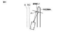
次に、ECU16は、車両1が左側走行車線R1を逸脱するか、言い換えれば、車両1の所定時間後の推定位置が中央区画線ML側の基準線をこえるか否かを判定する(ST205)。この判定処理について、詳細に説明する。図6は、車両1が中央区画線ML側の基準線を逸脱するか否か判定する処理を説明するための図である。
Next, the
図6に示すように、車両1は中央区画線MLと左区画線LLとで区画されている左側走行車線R1を走行しており、車両1の向きが若干中央区画線ML側に向いている。このとき、ECU16は、車速及びヨーレートに基づいて、所定時間後の車両1の到達位置を算出する。このときの車両1の推定位置は、車両1が直進したと仮定した場合は推定位置P1になる。しかしながら、実際の車両の旋回運動を考慮して、本実施形態では、前方注視2次予測モデルを用いて所定時間後の車両1の位置を推定する。前方注視2次予測モデルを用いて算出する推定位置P2は、推定位置P1より右側になる。このように、前方注視2次予測モデルを用いて車両1の位置を推定することにより、車両の旋回運動を考慮した推定位置になり、車両1の推定位置の精度を向上させることができる。そして、ECU16は、推定位置P2が基準線DL1より中央区画線ML側に位置しているか否かに基づいて、車両1が左側走行車線R1を逸脱するか否かを判定する。
As shown in FIG. 6, the
ここで、図5に戻り説明を続ける。車両1が左側走行車線R1を逸脱すると判定した場合(ST205:YES)、又は車両1が左側走行車線R1を逸脱しないと判定した場合(ST205:NO)それぞれ、ECU16は、判定結果を所定のメモリに記憶し(ST206)、ステップST105の処理へ進む。
Here, returning to FIG. 5, the description will be continued. When it is determined that the
ここで、図4に戻り説明を続ける。ECU11は、制御量演算を実行する(ST105:演算手段)。この制御量演算処理は、図7を参照しながら説明する。図7は、制御量演算処理の詳細の一例を示すサブフローチャートである。
Here, returning to FIG. 4, the description will be continued. The
ECU16は、基準線DL1に対する目標操舵角を演算する(ST401)。次に、ECU16は、基準線DL1に対する逸脱量を演算する(ST402)。ここで、逸脱量は、基準線DL1と第2推定位置P2との距離である(参照:図6)。次に、ECU16は、算出した逸脱量に応じて反映係数を演算する(ST403)。ECU16は、図3を参照して説明したグラフg1と算出した逸脱量とから反映係数を算出する。なお、ステップST205で逸脱しないと判定した場合は、反映係数がゼロに設定される。
The
ここで、再び図4に戻り説明を続ける。ECU16は、ステップST105で演算した目標操舵角及び反映係数を制御出力部22に出力し(ST106)、この処理はリターンになる。これにより、制御出力部22は、入力された目標舵角及び反映係数から操舵量を求め、演算した力(ニュートン)に基づいてパワーステアリング部17を制御する(抑制手段)。例えば、逸脱量が大きい場合には、大きい反映係数になり、パワーステアリング部17により車両1を車線内へ旋回させる動きをもたらす。これにより、車両1が左側走行車線R1を逸脱する動作を抑制することが可能になる。
Here, returning to FIG. 4 again, the description will be continued. The
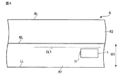
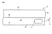
次に、車線幅に応じて基準線DL1を変更する作用について図8及び図9を参照して説明する。なお、基準線DL2も基準線DL1と同様の作用であるため、基準線DL1についてのみ説明する。 Next, the operation of changing the reference line DL1 according to the lane width will be described with reference to FIGS. 8 and 9. Since the reference line DL2 has the same action as the reference line DL1, only the reference line DL1 will be described.
図8に示す道路Rにおいて、左側走行車線R1の幅は車線幅W1である。一方、図9に示す道路Rにおいて、左側走行車線R1の幅は車線幅W2である。ここで、車線幅W1は車線幅W2より広い。このため、図8に示す基準線DL1と中央区画線MLとの距離は、図9に示す基準線DL1と中央区画線MLとの距離より広くなっている。言い換えれば、図9に示す基準線DL1の方が、中央区画線MLに寄っている。これにより、既述のように、車線逸脱抑制制御が及ばない幅を広く確保することができるため、不要な制御介入を抑制して煩わしさを低減させることができる。 On the road R shown in FIG. 8, the width of the left traveling lane R1 is the lane width W1. On the other hand, on the road R shown in FIG. 9, the width of the left traveling lane R1 is the lane width W2. Here, the lane width W1 is wider than the lane width W2. Therefore, the distance between the reference line DL1 and the center division line ML shown in FIG. 8 is wider than the distance between the reference line DL1 and the center division line ML shown in FIG. In other words, the reference line DL1 shown in FIG. 9 is closer to the center division line ML. As a result, as described above, it is possible to secure a wide range that the lane departure suppression control does not reach, so that it is possible to suppress unnecessary control intervention and reduce annoyance.
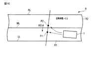
次に、逸脱量(既述の基準線DL1と推定位置P2との距離)に応じて反映係数を変更する作用について図10及び図11を参照して説明する。 Next, the operation of changing the reflection coefficient according to the deviation amount (the distance between the reference line DL1 and the estimated position P2 described above) will be described with reference to FIGS. 10 and 11.
図10に示す場合、逸脱量W3であり、この逸脱量W3に応じてグラフg1(参照:図3)から取得される反映係数は例えば0.2となる。一方、図11に示す場合、逸脱量W4(>W3)であり、この逸脱量W4に応じてグラフg1から取得される反映係数は例えば0.8となる。このように逸脱量が大きい方が、反映係数が大きくなっている。 In the case shown in FIG. 10, the deviation amount is W3, and the reflection coefficient acquired from the graph g1 (see FIG. 3) according to the deviation amount W3 is 0.2, for example. On the other hand, in the case shown in FIG. 11, the deviation amount is W4 (>W3), and the reflection coefficient acquired from the graph g1 according to the deviation amount W4 is 0.8, for example. The larger the deviation amount is, the larger the reflection coefficient is.
以上のように構成された車両1は、道路Rの車線の状態を検出するカメラ11及びカメラ制御部12と、カメラ11及びカメラ制御部12により検出した車線の状態と、車線の状態に応じて車線より車両1側に作成される基準線DL1,DL2と、車両1の所定時間後の推定位置P2とに基づいて、1車両が走行車線を逸脱するか否かを判定する逸脱判定部20と、車両1が左側走行車線R1を逸脱すると判定した場合、基準線DL1と推定位置P2との距離(逸脱量)に応じて操舵量を決定するための反映係数を設定し、この設定した反映係数と、基準線DL1に対する目標操舵角を演算する制御量演算部21と、演算した反映係数と目標舵角に基づいて操舵量を求め車両1の旋回方向の移動を抑制する制御出力部22とを備えている。このため、車両1は、車線の状態に応じて適切な車線逸脱抑制を実行することができる。
The
また、基準線DL1,DL2は車線幅が狭いほど中央区画線ML,左区画線LLに寄せて設定(作成)し、カーブの曲率が大きいほど、中央区画線ML,左区画線LLに寄せて設定(作成)する。これにより、車線幅が狭いときに、又はカーブ走行時に車線逸脱抑制制御が及ばない幅を広く確保することができるため、車両1は不要な制御介入を抑制して煩わしさを低減させることができる。
Further, the reference lines DL1 and DL2 are set (created) closer to the center division line ML and the left division line LL as the lane width is narrower, and are set closer to the center division line ML and the left division line LL as the curvature of the curve is larger. Set (create). As a result, when the lane width is narrow or the vehicle is traveling on a curve, it is possible to secure a wide range that the lane departure suppression control does not reach. Therefore, the
なお、上記実施の形態では、天候状態が悪いときに、車両逸脱抑制機能をOFFにする場合で説明したが、車両逸脱抑制機能をOFFする場合は、これに限るものではない。例えば、車両逸脱抑制機能のON/OFFを設定するスイッチが設けられている場合は、当該スイッチのON/OFFに基づいて、ECU16は、車両逸脱抑制機能のON/OFFを判定するように構成しても良い。
In the above embodiment, the case where the vehicle departure restraint function is turned off when the weather condition is bad has been described, but the case where the vehicle departure restraint function is turned off is not limited to this. For example, when a switch for setting ON/OFF of the vehicle deviation suppression function is provided, the
(変形例)
次に、上記実施の形態の変形例を説明する。
上記実施の形態と本変形例が異なるのは、反映係数を決定するためのグラフが上記実施の形態ではグラフg1の1つであったが(参照:図3)、本変形例では傾きの異なる複数のグラフg1,g2,g3になっている点である。なお、本変形例では、グラフg1,g2,g3の3つの場合で説明するが、グラフの数は2つ以上であれば良い。また、本変形例では、グラフg1からg3は線形の場合で説明するが、これに限るものではなく、非線形であっても良い。
(Modification)
Next, a modified example of the above embodiment will be described.
The present embodiment is different from the above embodiment in that the graph for determining the reflection coefficient is one of the graphs g1 in the above embodiment (see FIG. 3), but the inclination is different in this embodiment. This is a point where a plurality of graphs g1, g2, g3 are formed. In this modification, three graphs g1, g2, and g3 will be described, but the number of graphs may be two or more. Further, in this modification, the graphs g1 to g3 are described as being linear, but the present invention is not limited to this and may be non-linear.
図12は、反映係数を決定するための複数のグラフが記憶される一例を説明するための図である。これらのグラフg1,g2,g3は、既述の反映係数記憶部21aに記憶される(記憶手段)。
FIG. 12 is a diagram for explaining an example in which a plurality of graphs for determining the reflection coefficient are stored. These graphs g1, g2, g3 are stored in the reflection
図12に示すように傾きが異なる線形のグラフg1,g2,g3が示されている。グラフg3、グラフg2、グラフg1の順に傾きが大きくなっている。 As shown in FIG. 12, linear graphs g1, g2, g3 having different inclinations are shown. The gradient is increased in the order of the graph g3, the graph g2, and the graph g1.
ECU16は、例えば、車線の状態やST101にて読み込む走行環境に応じて、グラフg1からグラフg3のいずれかを選択するようにし、この選択したグラフに基づいて、反映係数を取得する。
For example, the
以上のように構成された車両1によると、グラフg1からグラフg3のうち車線幅や走行環境に適したグラフを選択して、反映係数を設定することができるため、より適した反映係数を設定することできる。
According to the
例えば、車線幅が狭い、中程度、広い場合に、ECU16は、グラフg3,g2,g1をそれぞれ選択する。このように構成すると車線幅に応じて演算で得られる最大の操舵量を抑制することができる。
For example, when the lane width is narrow, medium, and wide, the
また、例えば、好天候(晴天)と、悪天候(降雨)、悪天候(降雪)とでは、道路Rの路面と、車両1のタイヤとの摩擦力がそれぞれ異なる。このため、例えば、ECU16は、好天候時は傾きの最も小さいグラフg1を選択し、悪天候(降雨)時は傾きが中程度のグラフg2を選択し、悪天候(降雪)時は傾きが最も大きいグラフg3を選択して反映係数を求めるようにする。
Further, for example, the frictional force between the road surface of the road R and the tire of the
このように構成すると、車両1は走行環境に応じて適切な反映係数を選択することが可能になり、車線逸脱抑制機能をさらに向上させることができる。このような構成は、例えば、カメラ11を用いて左区画線LL,中央区画線MLが認識できなくても、車両1が左側走行車線R1の状態をナビゲーションシステム等により地図情報として取得し、且つ、車両1の位置をGPS(Global Positioning System)により特定できる構成の場合には、有効である。
With this configuration, the
なお、上記実施の形態においては、右側走行車線R2に車両1以外の他の車両が走行していない場合、つまり、対向車両がない場合について説明しているが、対向車両が存在する場合も想定される。対向車両の存在の有無は、撮影エリアAを広げることにより、カメラ制御部12で認識することが可能である。したがって、ECU16は、対向車両の存在が確認できる場合は、基準線DL1を中央区画線MLから一定距離遠ざけるように作成する。これにより、対向車両が中央区画線MLを若干超えて走行する状態が発生したとしても、車両1が対向車両と接触する可能性を防止することができる。
In the above embodiment, the case where no vehicle other than the
この発明は、上述した実施の形態そのままに限定されるものではなく、実施段階ではその要旨を逸脱しない範囲で構成要素を変形して具体化できる。また、上述した実施の形態に開示されている複数の構成要素の適宜な組み合わせにより種々の発明を形成できる。例えば、上述した実施の形態に示される全構成要素から幾つかの構成要素を削除しても良い。さらに、異なる実施形態の構成を組み合わせてもよい。 The present invention is not limited to the above-described embodiments as they are, and can be embodied by modifying the constituent elements within a range not departing from the gist of the invention in an implementation stage. Further, various inventions can be formed by appropriately combining a plurality of constituent elements disclosed in the above-described embodiments. For example, some constituent elements may be deleted from all the constituent elements shown in the above-described embodiment. Furthermore, the configurations of different embodiments may be combined.
1…車両、11…カメラ、13…車輪速センサ、14…ヨーレートセンサ、16…ECU、17…パワーステアリング部、20…逸脱判定部、21…制御量演算部、21a…反映係数記憶部、22…制御出力部、A…撮影エリア、R…道路、R1…左側走行車線、R2…右側走行車線、LL…左区画線、ML…中央区画線、RL…右区画線、g1,g2,g3…反映係数、P1…第1推定位置、P2…第2推定位置、DL1、DL2…基準線、W1,W2…車線幅、W3,W4…逸脱量 1... Vehicle, 11... Camera, 13... Wheel speed sensor, 14... Yaw rate sensor, 16... ECU, 17... Power steering part, 20... Deviation determination part, 21... Control amount calculation part, 21a... Reflection coefficient storage part, 22 ... control output unit, A... shooting area, R... road, R1... left lane, R2... right lane, LL... left lane, ML... central lane, RL... right lane, g1, g2, g3... Reflection coefficient, P1... First estimated position, P2... Second estimated position, DL1, DL2... Reference line, W1, W2... Lane width, W3, W4... Departure amount
Claims (7)
車線の状態を検出する車線状態検出手段と、
前記車線状態検出手段により検出した前記車線の状態と、前記車線の状態に応じて前記車線の区画線より車線中央側に作成される基準線と、前記車両の所定時間後の推定位置とに基づいて、前記車両が走行車線を逸脱するか否かを判定する判定手段と、
前記判定手段により前記車両が前記走行車線を逸脱すると判定された場合、前記車線を逸脱する逸脱量に応じて操舵量を決定するための反映係数を設定し、この設定した反映係数と、前記基準線に対する目標操舵角とに基づいて操舵量を演算する演算手段と、
前記演算手段により演算した操舵量に基づいて前記車両の旋回方向の移動を抑制する抑制手段と、
を備えることを特徴とする車線逸脱抑制装置。 A lane departure suppression device for suppressing lane departure of a vehicle, comprising:
Lane state detecting means for detecting the state of the lane,
Based on the state of the lane detected by the lane state detecting means, a reference line created on the lane center side of the lane marking in accordance with the state of the lane, and an estimated position of the vehicle after a predetermined time. A determining means for determining whether the vehicle deviates from the traveling lane,
When the determination means determines that the vehicle deviates from the traveling lane, a reflection coefficient for determining a steering amount according to a deviation amount deviating from the lane is set, and the set reflection coefficient and the reference value are set. a calculating means for calculating a steering amount based on the target steering wheel turning angle to the line,
Suppressing means for suppressing movement of the vehicle in the turning direction based on the steering amount calculated by the calculating means;
A lane departure suppression device comprising:
ことを特徴とする請求項1に記載の車線逸脱抑制装置。 The reference line is created according to the lane width of the lane and the curvature of the lane,
The lane departure suppression device according to claim 1, wherein
ことを特徴とする請求項2に記載の車線逸脱抑制装置。 The reference line is set closer to the division line as the lane width is narrower,
The lane departure suppression device according to claim 2, wherein
ことを特徴とする請求項2に記載の車線逸脱抑制装置。 As the curvature is larger, the reference line is set closer to the division line,
The lane departure suppression device according to claim 2, wherein
を備え、
前記逸脱量は、前記位置推定手段により推定される推定位置と、前記基準線との距離である、
ことを特徴とする請求項1に記載の車線逸脱抑制装置。 A position estimating means for estimating the position of the vehicle by using a forward gaze secondary prediction model;
Equipped with
The deviation amount is a distance between the estimated position estimated by the position estimating means and the reference line,
The lane departure suppression device according to claim 1, wherein
前記取得手段により取得する前記走行環境に基づいて、前記抑制手段を実行するか否かを決定する決定手段と、
を備えることを特徴とする請求項1に記載の車線逸脱抑制装置。 Acquisition means for acquiring the traveling environment of the vehicle,
Determination means for determining whether or not to execute the suppression means, based on the traveling environment acquired by the acquisition means,
The lane departure suppression device according to claim 1, further comprising:
を備え、
前記演算手段は、前記取得手段により取得する走行環境に応じて複数の前記グラフから1つを選択し、前記反映係数を設定する、
ことを特徴とする請求項6に記載の車線逸脱抑制装置。 Storage means for storing a plurality of graphs for determining the reflection coefficient,
Equipped with
The calculation means selects one from the plurality of graphs according to the traveling environment acquired by the acquisition means, and sets the reflection coefficient.
The lane departure suppression device according to claim 6, wherein.
Priority Applications (1)
| Application Number | Priority Date | Filing Date | Title |
|---|---|---|---|
| JP2016177674A JP6702107B2 (en) | 2016-09-12 | 2016-09-12 | Lane departure suppression device |
Applications Claiming Priority (1)
| Application Number | Priority Date | Filing Date | Title |
|---|---|---|---|
| JP2016177674A JP6702107B2 (en) | 2016-09-12 | 2016-09-12 | Lane departure suppression device |
Publications (2)
| Publication Number | Publication Date |
|---|---|
| JP2018043539A JP2018043539A (en) | 2018-03-22 |
| JP6702107B2 true JP6702107B2 (en) | 2020-05-27 |
Family
ID=61694131
Family Applications (1)
| Application Number | Title | Priority Date | Filing Date |
|---|---|---|---|
| JP2016177674A Active JP6702107B2 (en) | 2016-09-12 | 2016-09-12 | Lane departure suppression device |
Country Status (1)
| Country | Link |
|---|---|
| JP (1) | JP6702107B2 (en) |
Families Citing this family (4)
| Publication number | Priority date | Publication date | Assignee | Title |
|---|---|---|---|---|
| JP7213149B2 (en) * | 2019-06-06 | 2023-01-26 | 本田技研工業株式会社 | VEHICLE CONTROL DEVICE, VEHICLE, OPERATING METHOD AND PROGRAM OF VEHICLE CONTROL DEVICE |
| JP7348775B2 (en) * | 2019-08-28 | 2023-09-21 | 株式会社Subaru | Vehicle lane departure prevention control device |
| JP7371647B2 (en) * | 2021-03-03 | 2023-10-31 | トヨタ自動車株式会社 | Vehicle control device, control method, control program |
| CN114771517A (en) * | 2022-05-27 | 2022-07-22 | 三一重型装备有限公司 | Walking deviation rectifying method and system and vehicle |
Family Cites Families (4)
| Publication number | Priority date | Publication date | Assignee | Title |
|---|---|---|---|---|
| JP3292110B2 (en) * | 1997-09-22 | 2002-06-17 | トヨタ自動車株式会社 | Vehicle steering control device |
| JP5380860B2 (en) * | 2008-03-04 | 2014-01-08 | 日産自動車株式会社 | Lane maintenance support device and lane maintenance support method |
| JP5174609B2 (en) * | 2008-10-10 | 2013-04-03 | 日立オートモティブシステムズ株式会社 | Driving support device |
| JP6137979B2 (en) * | 2013-07-30 | 2017-05-31 | 株式会社Subaru | Lane departure prevention support device |
-
2016
- 2016-09-12 JP JP2016177674A patent/JP6702107B2/en active Active
Also Published As
| Publication number | Publication date |
|---|---|
| JP2018043539A (en) | 2018-03-22 |
Similar Documents
| Publication | Publication Date | Title |
|---|---|---|
| CN109421709B (en) | Driving Assistance Devices for Vehicles | |
| US9352778B2 (en) | Lane keeping assist system and method | |
| CN111066071B (en) | Position error correction method and position error correction device for driving assistance vehicle | |
| JP5966747B2 (en) | Vehicle travel control apparatus and method | |
| US11810369B2 (en) | Self-position estimation device | |
| US11130523B2 (en) | Driving supporter | |
| JP6702107B2 (en) | Lane departure suppression device | |
| CN107364443B (en) | Lane Keeping System for automated vehicle | |
| US10030969B2 (en) | Road curvature detection device | |
| JP6747079B2 (en) | Driving support device | |
| JP6088251B2 (en) | Vehicle travel support device | |
| JP6693893B2 (en) | Track recognition device | |
| CN110167813B (en) | Travel route recognition device and travel route recognition method | |
| US10162361B2 (en) | Vehicle control device | |
| JP6776707B2 (en) | Own vehicle position estimation device | |
| JP6407447B1 (en) | Traveling path recognition device and traveling path recognition method | |
| JP2020071122A (en) | Own vehicle position estimation device | |
| JP6105509B2 (en) | Runway estimation device and runway estimation program | |
| JP2010173601A (en) | Driving support device | |
| EP4001844A1 (en) | Method and apparatus with localization | |
| JP2019132762A (en) | Vehicle position estimating device | |
| JP6539129B2 (en) | Vehicle position estimation device, steering control device using the same, and vehicle position estimation method | |
| US11919567B2 (en) | Automatic steering control apparatus | |
| JP2018206071A (en) | Lane marking recognition device | |
| JP7378591B2 (en) | Travel route generation device |
Legal Events
| Date | Code | Title | Description |
|---|---|---|---|
| A621 | Written request for application examination |
Free format text: JAPANESE INTERMEDIATE CODE: A621 Effective date: 20190322 |
|
| A977 | Report on retrieval |
Free format text: JAPANESE INTERMEDIATE CODE: A971007 Effective date: 20200115 |
|
| A131 | Notification of reasons for refusal |
Free format text: JAPANESE INTERMEDIATE CODE: A131 Effective date: 20200121 |
|
| A521 | Written amendment |
Free format text: JAPANESE INTERMEDIATE CODE: A523 Effective date: 20200305 |
|
| TRDD | Decision of grant or rejection written | ||
| A01 | Written decision to grant a patent or to grant a registration (utility model) |
Free format text: JAPANESE INTERMEDIATE CODE: A01 Effective date: 20200407 |
|
| A61 | First payment of annual fees (during grant procedure) |
Free format text: JAPANESE INTERMEDIATE CODE: A61 Effective date: 20200420 |
|
| R151 | Written notification of patent or utility model registration |
Ref document number: 6702107 Country of ref document: JP Free format text: JAPANESE INTERMEDIATE CODE: R151 |