JP6720004B2 - Coke oven dismantling method - Google Patents
Coke oven dismantling method Download PDFInfo
- Publication number
- JP6720004B2 JP6720004B2 JP2016136897A JP2016136897A JP6720004B2 JP 6720004 B2 JP6720004 B2 JP 6720004B2 JP 2016136897 A JP2016136897 A JP 2016136897A JP 2016136897 A JP2016136897 A JP 2016136897A JP 6720004 B2 JP6720004 B2 JP 6720004B2
- Authority
- JP
- Japan
- Prior art keywords
- zone
- furnace
- cross tie
- brick
- dismantling
- Prior art date
- Legal status (The legal status is an assumption and is not a legal conclusion. Google has not performed a legal analysis and makes no representation as to the accuracy of the status listed.)
- Active
Links
Images


Landscapes
- Working Measures On Existing Buildindgs (AREA)
- Furnace Housings, Linings, Walls, And Ceilings (AREA)
Description
本発明は、炉団方向に炭化室と燃焼室とが交互に配置されたコークス炉の解体方法に関する。 The present invention relates to a method for dismantling a coke oven in which carbonization chambers and combustion chambers are alternately arranged in the furnace group direction.
図1は、コークス炉の概略図である(例えば、特許文献1)。この図1のようにコークス炉は、蓄熱室1の上に、炉団方向に薄い炭化室2と燃焼室3とが本を立て掛けるように交互に配置されている。炭化室2には、炭槽4に貯蔵された石炭がコークス炉の炉頂部上に配設された軌道5上を走行する装炭車6から装入されるようになっている。そして、装炭車6から炭化室2に装入された石炭は、燃焼室3で発生した熱で炭化室2が加熱されることにより乾留されてコークス化する。炭化室2でコークス化が完了すると、炭化室2の炉長方向の両側の窯口に設置した炉蓋を開放し、押出し機7により、炭化室2のコークスをプッシャーサイドPS(押出機側)の窯口からコークサイドCS(ガイド車側)の窯口まで押し出して排出する。
FIG. 1 is a schematic view of a coke oven (for example, Patent Document 1). As shown in FIG. 1, in the coke oven, a
炭化室2のコークサイドCSの窯口まで押し出されたコークスは、ガイド車8を介してコークス受け台車9に払い出され、コークス受け台車9に払い出されたコークス(赤熱コークス)は、冷却設備、例えば図示していないCDQ(コークス乾式消火設備)まで搬送される。なお、ガイド車8は、プラットホーム10上に配設された軌道(不図示)上を走行し、コークスの押し出しが行われる所定の炭化室2の窯口まで移動する。
The coke pushed out to the kiln mouth of the coke side CS of the
図2は、炉団方向に交互に配置された炭化室2及び燃焼室3の一部を上面平面視で示すものである。各燃焼室3を形成している煉瓦壁12が、PS側で立設している柱であるPSバックステイ14と、コークサイドCS側で立設している柱であるCSバックステイ15とに、炉体金物である保護板13bを介して支持されている。保護板13bまわりには、炉枠13a等の他の炉体金物13が炉蓋11周辺を補強するため配置されている。
炉体金物13は、具体的には、炉枠13a、保護板13bなどからなる。
FIG. 2 is a plan view showing a part of the
Specifically, the
また、PS側とCS側でそれぞれ向かい合うPSバックステイ14、CSバックステイ15とは、クロスタイロッドと呼ばれる棒鋼により炉上部等で連結されている。このクロスタイロッドと、バックステイの連結部では、スプリングにより炉中心方向に圧縮力(炉締力)を付与している(図2参照。)。
このように構築された煉瓦構造が緩まないように、炉長方向両端に垂直にPSバックステイ14、CSバックステイ15を配置し、両端のバックステイ間の炉締力によって煉瓦構造を拘束する。炉団長方向では、燃焼室配置部に対応してバックステイが配置される。バックステイは剛性の高いH形鋼であり、1本又は2本1組にして直立させ、炉長方向両端に配置する。炉長方向両端のバックステイの間には、上下に数本ずつのクロスタイロッドを配置し、このクロスタイロッドとCSバックステイ15とをナット46及びスプリング47を用いて接続することにより、両バックステイ間に締め付け力を発生させ、それによってバックステイ間の煉瓦構造を拘束している。以後、本明細書においてクロスタイロッドとは炉頂側に配置された上部のクロスタイロッドを意味する。
Further, the PS backstay 14 and the CS backstay 15, which face each other on the PS side and the CS side, are connected to each other by a steel bar called a cross tie rod at the upper part of the furnace or the like. At the connecting portion between the cross tie rod and the back stay, a compression force (furnace tightening force) is applied in the furnace center direction by a spring (see FIG. 2).
In order to prevent the brick structure thus constructed from loosening,
ところで、コークス炉を20年〜30年を越える期間で稼働して乾留、排出を繰り返すと、燃焼室3を形成している煉瓦壁12が劣化し、崩壊しやすくなる。このため、劣化した煉瓦壁12、PSバックステイ14、CSバックステイ15を撤去し、新たな煉瓦壁12を形成し、新たなバックステイを立設する更新工事が行われる。
By the way, when the coke oven is operated for a period of more than 20 to 30 years and carbonization and discharge are repeated, the
更新するに先立って、コークス炉を解体する際、特許文献1に記載されるような、一方の炭化室窯口等の開口部を防護壁で塞ぎ、その反対側から煉瓦壁を解体機で解体し、塞いだ方に向かって解体を進める技術が公知である(PS側から解体するなら、CS側の開口部を防護壁で塞ぎ、CS側から解体するなら、PS側の開口部を防護壁で塞ぐ。)。この技術において、防護壁はバックステイに固定し、防護壁を介して連結した全てのバックステイ下部に切れ目(弱み)を入れた後、外力を加えることで、バックステイを効率よく解体できるとしている。
Prior to renewal, when disassembling the coke oven, as described in
ここで、PS側、CS側のうち、解体機を設置する側を解体側、最後まで残る側を反対側ということにする。休止したコークス炉は、煉瓦の冷却収縮で稼働中よりも上部クロスタイロッドによる炉締め力は低下する。かつバックステイ近傍の煉瓦は保護板とのセリで、炉中心側よりも煉瓦の沈下が少なく、その結果窯口近傍の煉瓦目地は切れて開きやすく、煉瓦構造体としてやや緩む。そのため、特に防護壁も設けられておらず、解体の振動も直接伝わる解体側からの解体中の振動で煉瓦が崩落したり、保護板が脱落するリスクが高い。また、煉瓦を撤去する際には、上部クロスタイロッドを撤去するので、炉締め力はさらに低下する。さらに窯口金物(炉枠、保護板)は、煉瓦に対してバックステイで押しつけて固定しているが、上述のように煉瓦の冷却収縮と、上部クロスタイロッドの撤去で押しつけ力は弱まるため脱落しやすい。さらに、長期間使用している間に保護板や炉枠に亀裂が入るため、脱落リスクが高まる。特許文献1には、解体側のバックステイや窯口金物(炉枠、保護板等)の解体についての規定は無い。このようなことから休止したコークス炉の解体側の窯口近傍の作業は、作業者の安全が十分に確保できない問題があった。
本発明は、コークス炉を休止して煉瓦を解体して更新する工事において、反対側の窯口等の開口部を防護壁で塞ぎ、解体側から煉瓦壁を解体機で解体する方法において、解体機運転手及び周辺作業者の安全を確保するために、煉瓦及び窯口金物(保護板、炉枠)の崩落と落下を防止する工法を提示することを目的とする。
Here, of the PS side and the CS side, the side on which the dismantling machine is installed is referred to as the dismantling side, and the side remaining until the end is the opposite side. In the coke oven that has stopped, the furnace tightening force by the upper cross tie rods is lower than that in operation due to cooling shrinkage of bricks. Moreover, the bricks near the back stay are agglomerated with the protective plate, so that the bricks do not sink more than the center side of the furnace. As a result, the brick joints near the kiln opening are easy to cut and open, and the brick structure loosens slightly. Therefore, there is no particular protection wall, and there is a high risk that the bricks will collapse or the protective plate will fall off due to the vibration during dismantling from the dismantling side, which directly transmits the vibration of the dismantling. Moreover, when removing the bricks, the upper cross tie rods are removed, so the furnace tightening force is further reduced. Furthermore, the kiln mouth fittings (furnace frame, protective plate) are fixed against the bricks by pressing them with the back stay, but as mentioned above, the cooling force of the bricks and the removal of the upper cross tie rods weaken the pressing force, so they fall off. It's easy to do. Moreover, the protective plate and furnace frame are cracked during long-term use, which increases the risk of falling. In
INDUSTRIAL APPLICABILITY The present invention is a method of dismantling a brick by dismantling and renewing a brick by dismantling a brick wall from a dismantling side by a dismantling machine in a construction in which a coke oven is stopped and the brick is dismantled and updated. In order to ensure the safety of the operator and surrounding workers, the purpose is to present a construction method that prevents the bricks and kiln mouth fittings (protective plates, furnace frames) from collapsing and falling.
上記の課題を解決するための本発明の要旨とするところは、以下のとおりである。
(1)燃焼室と炭化室が交互に配置されるコークス炉の解体方法であって、PS側(プッシャーサイド)、CS側(コークサイド)のうち、解体機を設置する側を解体側、最後まで残る側を反対側とし、以下の手順を繰り返すことにより、コークス炉を炉団方向に一部ずつ分割したゾーン毎に煉瓦を解体することを特徴とするコークス炉の解体方法。
1)PS側、CS側それぞれ、隣り合うバックステイを炉団方向に連結する横梁を上部クロスタイロッドの下部に設置し、横梁の両端は擁壁又はデッキに固定する。
2)一度に解体する1ゾーンの炉団方向の長さ範囲の両端であるバックステイに連結されている上部クロスタイロッドのテンションは保持し、テンションを保持した両端の上部クロスタイロッド間にある上部クロスタイロッドのテンションはすべて開放する。テンションを保持した上部クロスタイロッドのみ、前記上部クロスタイロッドの端部の両方をそれぞれの上部クロスタイロッドが連結されているバックステイに固定する。
3)前記一度に解体する1ゾーンの炉団方向の長さ範囲中、テンションを開放した上部に接続されていた、解体側のバックステイにおいて、切れ目を入れる。
4)解体側のバックステイ横梁において、一度に解体する1ゾーンの炉団方向の長さ範囲の横梁(1ゾーン分の横梁)が、その両側に隣接するゾーンの横梁から切断された状態とする。
5)前記横梁を切除した範囲(前記一度に解体する1ゾーンの炉団方向の長さ範囲)内の上部クロスタイロッド1組以上を切断又は切除後、前記上部クロスタイロッドを切断したバックステイを前記切れ目から、炉体金物が引き抜ける程度に倒したあと、前記炉体金物を撤去する。
6)前記切れ目を入れていたバックステイの切れ目より上部を撤去し、煉瓦を露出させる。
7)解体側からその奥に向かって、バックステイの切れ目より上部を撤去することにより煉瓦を露出させた、テンションを保持した両端の上部クロスタイロッド間のゾーン(1ゾーン)の煉瓦を解体、掻き出す。
8)解体側に煉瓦崩落の危険が無くなるまで煉瓦を掻き出して減少させるか、または煉瓦の高さが十分に低くなるまで除去した後、別のゾーンに移り、煉瓦を解体する。
(2)前記1)〜3)を解体予定のゾーンすべてについて行った後、各々のゾーンについて、それぞれ4)〜8)を繰り返して行いゾーンの解体を行う(1)に記載のコークス炉の解体方法。
(3)前記7)の煉瓦を解体、掻き出す前に、解体する予定のゾーンのそれぞれすべてについて、前記1)を行い、さらに、前記2)〜6)をバックステイ、上部クロスタイロッド、炉体金物に対して行い、煉瓦を露出させてから煉瓦を解体する(1)に記載のコークス炉の解体方法。
(4)前記一度に解体する炉団方向の長さ範囲の両端の上部クロスタイロッドの間隔(1ゾーンの間隔)は、3〜10組である(1)〜(3)のいずれか1に記載のコークス炉の解体方法。
(5)前記1)と2)の間に、反対側のバックステイとプラットホームをつなぐ斜材を設置する工程を設ける(1)〜(4)のいずれか1に記載のコークス炉の解体方法。
The gist of the present invention for solving the above problems is as follows.
(1) A method for dismantling a coke oven in which combustion chambers and carbonization chambers are alternately arranged, and the PS side (pusher side) or the CS side (coke side) is the dismantling side, the side on which the dismantling machine is installed is the last. A method for disassembling a coke oven, characterized in that the bricks are disassembled in each zone where the coke oven is divided into parts in the furnace group direction by repeating the following procedure with the remaining side as the opposite side.
1) On each of the PS side and the CS side, a horizontal beam connecting adjacent backstays in the furnace group direction is installed under the upper cross tie rod, and both ends of the horizontal beam are fixed to a retaining wall or a deck.
2) The upper cross tie rods that are connected to the back stays, which are the ends of the length range in the furnace group direction of one zone to be dismantled at a time, hold the tension, and the upper cross between the upper cross tie rods that holds the tensions. Release all tie rod tension. Only the upper cross tie rod holding the tension and both ends of the upper cross tie rod are fixed to the back stay to which the respective upper cross tie rods are connected.
3) Make a break in the back stay on the dismantling side, which was connected to the upper part where the tension was released, in the length range in the furnace group direction of the one zone to be dismantled at once.
4) In the backstay horizontal beam on the dismantling side, the horizontal beams within the length range in the furnace group direction of one zone to be dismantled at one time (horizontal beams for one zone) are cut from the horizontal beams of the zones adjacent to both sides. ..
5) After cutting or cutting one or more sets of upper cross tie rods within the range (length range in the direction of the furnace group of one zone to be disassembled at a time) in which the cross beam is cut, the back stay in which the upper cross tie rods are cut is described above. After depressing the furnace metal fittings from the cuts to such an extent that they can be pulled out, the furnace metal fittings are removed.
6) Remove the upper part from the break of the backstay where the cut was made to expose the brick.
7) From the dismantling side toward the back, the brick is exposed by removing the upper part from the break of the backstay, and the brick in the zone (1 zone) between the upper cross tie rods at both ends that holds tension is dismantled and scraped out. ..
8) After reduce or by scraping the bricks until the risk of brick collapse becomes no, or the height of the brick was removed to low enough dismantling side, move to another zone, to dismantle the bricks.
(2) The coke oven dismantling according to (1), wherein after performing the above 1) to 3) for all zones to be dismantled, the zones are disassembled by repeating 4) to 8) for each zone. Method.
(3) Before dismantling and scraping the brick of 7) above, 1) is carried out for each of the zones to be dismantled, and further 2) to 6) are backstayed, upper cross tie rods, and furnace metal fittings. The method for disassembling a coke oven according to (1), wherein the brick is exposed and then the brick is disassembled.
(4) The intervals (intervals in one zone) of the upper cross tie rods at both ends of the length range in the furnace group direction to be disassembled at once are 3 to 10 sets (1) to (3) Method for dismantling coke ovens in Japan.
(5) The method for disassembling a coke oven according to any one of (1) to (4), wherein a step of installing a diagonal member connecting the back stay and the platform on the opposite side is provided between 1) and 2).
本発明により、特に解体側への、煉瓦、炉枠、保護板の飛来落下防止ができ、バックステイ、炉枠、保護板の反炉側への転倒が防止できる。 According to the present invention, it is possible to prevent the bricks, the furnace frame, and the protective plate from falling and falling toward the dismantling side, and to prevent the backstay, the furnace frame, and the protective plate from falling over to the anti-furnace side.
本発明は、燃焼室と炭化室が交互に配置されるコークス炉の解体方法において、コークス炉を炉団方向に一部ずつ小分割したゾーン毎に煉瓦を解体することを特徴とする。小分割ゾーンに分割することで、大量の煉瓦や炉体金物が一度に崩落する危険が減少し、安全に解体することができる。そのための各手順について、以下に図3〜7を参照し、詳細に説明する。以下の例はPS側を解体側とした説明であるが、本発明は、CS側からの解体でも同様に解体することができるので、PS側からの解体に制限されるものではない。
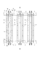
図3は、コークス炉の上方向から見た平面図である。図3において、点線で示したのは、テンションを開放したテンション解放クロスタイロッド16bである。一方、実線で示したのは、テンション保持クロスタイロッド16aである。PSバックステイ14及びCSバックステイ15は、それぞれ、相互に対応する位置のバックステイと、点線及び実線で示される二組の上部クロスタイロッド16により接続されていることを示している。また、上部クロスタイロッド以外は、断面図として表記している。
The present invention is a method of dismantling a coke oven in which combustion chambers and carbonization chambers are alternately arranged, characterized in that the bricks are disassembled in each zone into which the coke oven is subdivided in the furnace group direction. Dividing into small division zones reduces the risk of a large amount of bricks and furnace metal fittings collapsing at once, and can be safely disassembled. Each procedure therefor will be described in detail below with reference to FIGS. Although the following example describes the case where the PS side is the disassembly side, the present invention is not limited to disassembly from the PS side because disassembly from the CS side can be similarly disassembled.
FIG. 3 is a plan view of the coke oven viewed from above. In FIG. 3, what is indicated by a dotted line is the tension release
1)工程
図3に示したように、最初に、PS側、CS側のそれぞれに設けられているそれぞれの側の同士のバックステイを、炉団長方向に横断する横梁17によりすべて連結する。そして、さらに、横梁17の両端を擁壁18、又は、デッキに固定する。ここで、擁壁18は、炭化室2、燃焼室3の配置が終了した炉団方向の最外端に設けられている鉄筋コンクリート製の頑丈な壁である。デッキとは、頑丈な構造物である。これらの擁壁18、デッキは、煉瓦を積み重ねた炭化室2、燃焼室3の間の壁に比して十分な強度があるため、擁壁18、又は、デッキに横梁17を固定することにより、バックステイを連結した横梁17を支えることができる。こうすることにより、擁壁18又はデッキで間接的にバックステイを支える。長い一本の横梁17でPS側、あるいはCS側のすべてのバックステイを連結してもよいし、短い複数の横梁を各々のバックステイに連結させて、結果としていずれかの側のバックステイすべてが横方向に連結されればよい。
このように横梁17を上部クロスタイロッドの下部に設置することにより、炉枠が拘束されるため、煉瓦、炉枠13a、保護板13b等の炉体金物の飛来、落下が防止でき、バックステイ、炉枠13a、保護板13bの炉外側への転倒が防止できる。
1) Process As shown in FIG. 3, first, all the back stays on the PS side and the CS side, which are provided on the respective sides, are all connected by a
By installing the
2)工程
本発明は、煉瓦を一度に掻き出す範囲を小分割し、小分割範囲(ゾーン)以外の煉瓦等が崩れないようにするものである。本工程は、小分割する範囲の決定に関する工程といえる。
上部クロスタイロッドは、PS側とCS側のバックステイ同士をつないで炉締め力により炉の煉瓦を保持している。炉の運転を止めると、煉瓦が冷えて収縮するので、炉締め力が弱まる。さらに、煉瓦を解体するために上部クロスタイロッドを撤去すると、炉締め力がなくなるので、煉瓦等が崩壊しやすい。そこで、数組に一組の割合でテンション(PS側及びCS側バックステイ間の張力)を保持した上部クロスタイロッド(テンション保持クロスタイロッド16a)組を設け、前記組間の複数組の上部クロスタイロッド(テンション解放クロスタイロッド16b)組のテンションを開放する。テンション保持クロスタイロッド16aの一組とそれにつながるPS側及びCS側バックステイにより締め付けられる部分の炉体煉瓦(燃焼室を構成する煉瓦壁12)は、炉の冷却により炉締め力が弱まっているが、それでも締め付けられているので崩壊しにくい。一方、テンション解放クロスタイロッド16b近傍の炉体煉瓦は緩んでいるので、取り壊しやすい。すなわち、テンション保持クロスタイロッド16aの締め付けにより、一種の崩壊しがたい壁のようなものを炉団方向垂直に設けるのである。これにより、煉瓦を取り壊して掻き出す際に大規模な崩壊が起こらない、必要な小分割ゾーンを区切ることができる。この小分割ゾーンは、上部クロスタイロッド3組〜10組の間として設定することが好ましい。上部クロスタイロッドはバックステイに二本一組なので、バックステイでいえば3本(テンションなしは間に3本、4本毎にテンションあり)から10本間隔(テンションなしは間に10本、11本毎にテンションあり)でバックステイに連結されている上部クロスタイロッドのテンションを保持することが好ましい。10組を超えると、一つのゾーンが広すぎて崩壊の危険が高まるし、2組以下であれば狭すぎるので、解体の際の効率が悪い。好ましい一つのゾーンの炉団方向の長さは距離に換算すると5〜15mである。
具体的にテンションを保持するには、図4に示したように、上部クロスタイロッドの締め付けスプリング47をナット46で締め上げているまま、その状態で、上部クロスタイロッドとバックステイの間を溶接点21で溶接すること等により固定する。このように固定することにより、解体が進み、煉瓦が除去された後に、バックステイが解体側に倒れることを防止することができる。煉瓦の冷却収縮により低下した炉締め力をさらに向上させるために、さらに締め上げてもよい。一方、テンションを緩めるには、スプリング47を拘束しているナット46を緩めればよい。
2) Process In the present invention, the range in which bricks are scraped at once is divided into small pieces so that bricks and the like other than the small divided areas (zones) are not broken. It can be said that this step is a step relating to determination of a range to be subdivided.
The upper cross tie rod connects the PS-side and CS-side backstays to each other and holds the brick of the furnace by the clamping force of the furnace. When the furnace is stopped, the brick cools and shrinks, weakening the furnace tightening force. Furthermore, when the upper cross tie rod is removed to dismantle the brick, the furnace tightening force is lost, and the brick or the like is likely to collapse. Therefore, an upper cross tie rod (tension holding
To hold the tension concretely, as shown in FIG. 4, while the tightening
3)工程
解体するゾーン中で、解体側のバックステイ(図3においてはPSバックステイ14b)において、切れ目を入れる。この切れ目を入れるバックステイは、テンションを開放したテンション解放クロスタイロッド16bに連結されていたPSバックステイ14bである。バックステイは、断面H形のH形鋼を使用しており、Hの一面が炉体に密着して炉体の膨張を抑制している。バックステイに入れる切れ目は、炉側片フランジ残しておくことが好ましい。これは、H形鋼の炉体に密着していないT部分まで切ることであり、炉体に密着している直線部分はつながったままとしておく。このように一部をつながったままとしておくことにより、後の5)工程におけるバックステイを炉体金物13が引き抜ける程度に倒すことが行いやすくなる。切れ目を上記のように入れることにより、PSバックステイ14bを炉手前方向に曲げ倒しやすくなり、曲げることにより生まれた隙間から煉瓦とPSバックステイ14bに挟まれた炉体金物13を引き抜きやすくすることができる。また、PSバックステイ14bを折り曲げるまで、さらには、折り曲げてからも、ある程度はPSバックステイ14bが炉体金物13を支えることができる(図5参照)。炉体金物13がある程度PSバックステイ14bに支えられているため、PSバックステイ14bを一度に撤去する場合と異なり、炉体金物13がいきなり倒壊、落下することを防止できる。さらに、PSバックステイ14bを小さな外力で効率よく撤去できるので、PSバックステイ14bの解体側への倒壊防止が可能である。そして、外力が小さくてすむので、残存煉瓦への外力(振動、衝撃)も緩和され、煉瓦崩落も防止できる。
なお、PSバックステイ14bの切れ目は、PSバックステイ14bの最上部、すなわち、テンション解放クロスタイロッド16bからある程度下であれば、どこに設けてもよいが、PS側バックステイ14bの燃焼室3の床面高さ程度の高さに設けることや、燃焼室3の床面高さとテンション解放クロスタイロッド16bの中間高さに設けることができる。炉の高さが高い場合は、燃焼室3の床面高さに切れ目を設けると、後にPSバックステイ14bを切れ目から切断して除去した際に、高く積みあがっている劣化した煉瓦を支えるものがなくなる。一方、中間高さあたりに切れ目を入れ、それよりも上のPSバックステイ14bのみを除去し、その後、除去したPSバックステイ14bのあった高さより上の煉瓦をまず掻き出せば、一度に煉瓦が倒壊する危険を減らすことができる。このように、炉の上部の煉瓦を段階的に取り除くならば、PSバックステイ14bの切れ目はある程度以上の所定の高さに入れることが好ましい。また、PSバックステイ14bを一度に取り除いても煉瓦が倒壊しない高さであれば、工程が減るので、低い位置に切れ目を入れることが好ましい。切れ目を入れる好ましい高さは、燃焼室床面の高さを基準として−1〜3mである。
3) Step In the zone to be disassembled, a break is made in the disassembly side backstay (
The break of the
4)工程
解体側のバックステイを連結した横梁17において、一度に解体する1ゾーンの炉団方向の長さ範囲の横梁17(1ゾーン分の横梁)が、その両側に隣接するゾーンの横梁17から切断された状態とする。最初のゾーンが解体される前は、横梁17は二か所を切断しなければならない。一方、最初のゾーンが解体された次に、その隣のゾーンを解体する場合は、切断は一か所でよいので、両隣のゾーンの横梁17から「切断された状態」とした。たとえば、最初の1ゾーンを解体するには、解体側の横梁17のうち、テンション保持クロスタイロッド16a間の横梁17を二か所で切断する。この工程は、解体予定のゾーンを塞ぐ横梁17の一部分を切断することで、解体機が炉の解体予定の煉瓦にアクセスできるようなアクセス口をつくる最初の工程である。テンション保持クロスタイロッド16a間のみの横梁17を切断、あるいは切断して除去することで、他の部分の強度が保たれ、目的のゾーンのみ(図3のゾーン(B)の中だけ)を安全に解体することができる。
4) Process In the
5)工程
横梁17を切断した範囲内のテンション解放クロスタイロッド16b1組以上を切断又は切除後、前記切断したテンション解放クロスタイロッド16bに連結されているPSバックステイ14bを炉体金物13が引き抜ける程度に倒したあと、前記PSバックステイ14bの切れ目より上部の炉体金物13を撤去する。横梁17を切除した範囲内のテンション解放クロスタイロッド16bの1組以上を切断又は切除するのは、解体側の当該PSバックステイ14bを倒せるようにするためである。また、炉体金物13を除去しておくのは、煉瓦解体前に予めその落下を防止するためである。テンション解放クロスタイロッド16bを切断したPSバックステイ14bを炉体金物13が引き抜ける程度に倒すのは、3)工程で説明したように、炉体金物13を除去するまで、ある程度はPSバックステイ14bによって支えるためである。
また、本工程は、解体側のPSバックステイ14bを倒して、炉体金物13を撤去することにより、煉瓦を掻き出せるよう、解体側に露出させる準備をするための工程でもある。なお、PSバックステイ14bは切れ目から倒れるので、切れ目から上にPSバックステイ14bと煉瓦の隙間ができ、炉体金物13がまず取り出せる。
5) Step After cutting or cutting off one or more sets of the tension release
Further, this step is also a step for preparing to expose the bricks by scraping the bricks by scraping down the
6)工程
切れ目を入れていたPSバックステイ14bの切れ目より上部を撤去し、煉瓦壁12を露出させる。切れ目より上のPSバックステイ14bを撤去することにより、解体機が炉の煉瓦にアクセスできるようなアクセス口を作ることができる。PSバックステイ14bの撤去は、切れ目から上部と下部を複数回に分けてもよいし、切れ目をPSバックステイ14bの根元に入れて一度で行ってもよい。
6) Step The upper part of the
7)工程
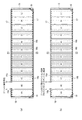
解体側からその奥に向かってテンション保持クロスタイロッド16aの両端間のゾーン(図3のゾーン(B)で示される1ゾーン)の煉瓦を解体、掻き出す(図6(a)参照)。上記の1ゾーンは、反対側は、横梁17によりバックステイが連結されて強化されている。また、この1ゾーンは、テンション保持クロスタイロッド16aのテンションが保持されていることにより炉締め力が負荷されている煉瓦壁12二枚に囲まれている。この二枚の煉瓦壁12は、それぞれ、PSバックステイ14、CSバックステイ15と、両者を連結したテンション保持クロスタイロッド16aより、締付け力で炉体が強化されているので、煉瓦壁12が崩れにくく、安全性が高い。一方、上記の崩れにくい煉瓦壁12に挟まれる領域は、煉瓦にテンションがかかっていないので、容易に撤去することができる。また、1ゾーンが小さいので、この範囲の煉瓦は相対的に少量であり、大量に崩れることがないので、解体時の煉瓦の崩落による危険が少ない。さらに、解体側のバックステイ14bはすでに撤去され、炉体金物13も撤去されているので、炉体金物13が脱落する危険もない。なお、ゾーン(B)解体後にゾーン(C)を解体する場合は、ゾーン(B)(C)間のテンション保持クロスタイロッド16aにより、締付け力で炉体が強化された煉瓦壁12は撤去されるが、ゾーン(D)側の煉瓦壁12が残っているので、ゾーン(C)の解体によるゾーン(D)方面の連鎖的な崩壊は防止できる。
7) Step From the dismantling side to the inner side thereof, the brick in the zone (one zone shown by zone (B) in FIG. 3) between both ends of the tension holding
8)工程
十分に煉瓦を掻き出して、撤去した後、別のゾーンに移り、煉瓦を解体する。別のゾーンに移るのは、おおよそ、解体側に煉瓦崩落の危険が無くなるまで煉瓦を掻き出して、減少させたとき、あるいは、煉瓦の高さが十分に低くなるまで除去された場合をいう。特段厳しい規定を設けるものではなく、通常の常識的に当該ゾーンの煉瓦を処理できたら別のゾーンに移って、同様に煉瓦を解体する。
なお、ゾーン(B)の煉瓦を撤去した後、隣接するゾーン(C)の煉瓦を撤去する場合、ゾーン(B)とゾーン(C)間の、テンション保持クロスタイロッド16aと、そのクロスタイロッドによって、締め付けられている煉瓦壁、および、上記クロスタイロッドと連結されているPSバックステイ14aを撤去する手順は、たとえば、図6に示したように、次のように行う。図6(a)のように、ゾーン(B)の煉瓦を撤去したら、図6(bのように、ゾーン(B)とゾーン(C)の間のテンション保持クロスタイロッド16aのテンションを開放する。その後、図6(c)のように、PSバックステイ14b、ゾーン(C)とゾーン(D)の間の横梁を切断し(この横梁は予め切断しておいてもよい。)、ゾーン(C)の切れ目を入れておいたPSバックステイ14(切れ目を入れるのは、引き倒す直前でもよい。)、テンションを開放したゾーン(B)とゾーン(C)の間を仕切っていたPSバックステイ14(元PSバックステイ14a)を引き倒して、炉体金物を撤去する。そして、図6(d)のように、ゾーン(C)中の煉瓦を撤去する。
8) Process After scraping bricks out and removing them, move to another zone and dismantle bricks. Moving to another zone is roughly when the brick is scraped to the demolition side until the risk of brick collapse disappears and reduced, or when it is removed until the height of the brick becomes sufficiently low. No particular strict rules are set, and if the common sense can handle the bricks in the zone, move to another zone and dismantle the bricks in the same way.
In addition, when removing the bricks of the adjacent zone (C) after removing the bricks of the zone (B), the tension holding
1)〜8)工程を行う順序は、数字の順のとおりであるが、各ゾーンを撤去する際、どの工程までを行ってから、各ゾーンの煉瓦の解体に入るかは、種々の方法がある。
本発明の好ましい態様は、1)工程後、2)、3)までの工程をまず最初に各ゾーンにおいて済ませておき、その後、煉瓦を一度に掻き出す一つ一つのゾーンにおいて、4)〜8)の工程を繰り返す方法である。2)、3)を予め各ゾーンにおいてまとめて済ませてしまうことにより、作業効率が向上する。4)〜6)工程、たとえば4)工程の横梁17の切断は、7)工程の煉瓦掻き出し前に複数のゾーンについて行っておくと、掻き出すゾーンの解体側炉周辺の強度が低下し、炉の崩壊の危険が高まるのであまり好ましくない。炉体金物13除去、PSバックステイ14bの除去に関する5)、6)工程も同様である。また、一つのゾーンの煉瓦を掻き出し除去した後、次に煉瓦を掻き出し除去するゾーンはその隣のゾーンが好ましい。とびとびのゾーンを処理するとなると、それだけ、横梁を各所で分断しなければならず、一部擁壁18やデッキに固定されない横梁が生じ、さらにバックステイを支える横梁の長さが短くなるので、強度が低下する。
ただし、効率を重視するならば、テンション保持クロスタイロッド16aによって仕切られた複数のゾーンから同時に煉瓦を解体側に露出させて、複数の解体機により各々同時に掻き出してもよい。
また、解体側は、広く、作業しやすいので例示したPS側が好ましい。
The order of performing steps 1) to 8) is in the order of the numbers, but when removing each zone, various methods are used to determine which step is performed before starting the demolishing of bricks in each zone. is there.
In a preferred embodiment of the present invention, the steps from 1) to 2) and 3) are first performed in each zone, and then 4) to 8) in each zone in which bricks are scraped at once. This is a method of repeating the step. By combining 2) and 3) in advance in each zone, work efficiency is improved. If the
However, if importance is placed on efficiency, bricks may be simultaneously exposed to the demolition side from a plurality of zones partitioned by the tension holding
In addition, the dismantling side is wide and easy to work, so the exemplified PS side is preferable.
また、図7に示すように、1)と2)の間に、反対側のバックステイであるCSバックステイ15とプラットホームをつなぐ斜材20を設置する工程を設けることが好ましい。反対側は、各ゾーンの煉瓦を処理した後に、最後に撤去されるので、それまでに倒壊することは防がなければならない。台車が通行するプラットホームとCSバックステイ15は溶接されておらず、CSバックステイ15は自立しているため、反対側のバックステイに、プラットホームとつなぐ斜材を設けて、プラットホームとCSバックステイ15の倒壊を防止することが好ましい。
[具体的な実施態様]
Further, as shown in FIG. 7, it is preferable to provide a step between 1) and 2) of installing a
[Specific Embodiment]
図3〜5により本発明の解体方法の実施態様を、PS側に解体機を設置する場合、すなわち、PS側から解体する場合を例として説明する。 An embodiment of the disassembling method of the present invention will be described with reference to Figs.
1)工程において、バックステイを補強する横梁17は、PSバックステイ14同士、CSバックステイ15同士を連結して設置される。さらに、横梁17は、擁壁18に、筋交い19により固定する。固定はボルト止め、溶接等により行う。
In the step 1), the
なお、この時までに、コークス炉を休止して冷却する際に炉蓋11を撤去することにより開放した、解体側及び反対側の炭化室窯口開口部は仮蓋等により塞いでおくとよい。塞いでおかないと、この開口部から煉瓦、炉枠、保護板の飛来落下が起こるためである。具体的には、PSバックステイ14同士間あるいはCSバックステイ15同士間に、煉瓦等の落下、倒壊から作業員を保護するための壁あるいは金網等を設置するのもよい。また、同時に、反対側のバックステイとプラットホームをつなぐ斜材20(筋交い)を設置しておくとよい。
In addition, by this time, it is advisable to close the charring chamber kiln opening openings on the dismantling side and the opposite side, which were opened by removing the
横梁17によりPSバックステイ14、CSバックステイ15同士を各々連結し、擁壁18に固定したら、2)工程においては、バックステイ3本(上部クロスタイロッド3組)飛ばし毎の、実線で示されたテンション保持クロスタイロッド16a一組2本ずつを、それぞれ、テンション保持クロスタイロッド16aが連結しているバックステイに固定する。次に、テンション保持クロスタイロッド16a同士の炉団方向間の、点線で示されたテンション解放クロスタイロッド16bのテンションを開放する。このようにテンション保持クロスタイロッド16aによって、A〜Lに示したような小領域のゾーンに分割される。
When the
3)工程として、テンション解放クロスタイロッド16bに接続されていたPS側のバックステイ14bの所定の高さに切れ目を入れる。切れ目を入れるのは、H形鋼の炉外側のTの部分までである。切れ目はガスバーナー等により入れることができる。
3) As a step, a cut is made at a predetermined height of the PS-
3)工程後には、4)〜6)工程により、煉瓦を露出させるが、その前までに、炉の上昇管や、PS側のプラットホーム等を撤去しておくとよい。また、プラットホーム下にある変更弁接続口と煙道頂版上に鉄板を敷設するなどして、解体側であるPS側周辺の足場を確保しておくとよい。 After step 3), the bricks are exposed in steps 4) to 6), but it is advisable to remove the rising pipe of the furnace, the PS side platform, etc. before that. Further, it is advisable to secure a scaffold around the PS side, which is the dismantling side, by laying an iron plate on the change valve connection port under the platform and on the flue top plate.
図3のBの領域1ゾーン(ゾーン(B))の煉瓦を最初に掻き出す場合について述べる。4)工程として、テンション保持クロスタイロッド16a間X1〜X2の間の横梁を切断する。すなわち、X1、X2の点で横梁を切断する。この際は、解体機のアーム先端に取り付けたニブラや、ガスバーナー等によって横梁を切断することができる。切断された横梁はバックステイ14bから切除されてもよいし、この段階ではバックステイ14bに接合したままでもよい。
A case where the brick in the
次に、5)工程として、ゾーン(B)のPSバックステイ14に接続されているクロスタイロッド16bを、各々切断する。横梁17が、ゾーン(B)の間で二か所切断されていること、及び、クロスタイロッド16bが切断されたことにより、バックステイ14bを炉外側方向に切れ目から倒すことができる。バックステイ14bを図5(a)に示したように、傾けることで、当該14bによって保持されていた炉体金物13を除去できる。
Next, in step 5), the
炉体金物13を除去したら、6)工程として、バックステイ14bを切れ目から撤去する。バックステイ14bが撤去されれば、ゾーン(B)の炉団方向幅では、除去されて残るバックステイ14bより上の高さの煉瓦が露出しているから、7)工程として、この部分の比較的少量の煉瓦を掻き出して、図5(b)に示したように処理する。必要に応じて、残ったバックステイ14bを根元から除去し、切れ目より下の煉瓦を露出させてPS方向から煉瓦を掻き出して処理する。
After the furnace
ゾーン(B)の煉瓦の処理が終了したら、8)工程として、同様の工程を繰り返し、ゾーン(A)、ゾーン(C)と、隣接するゾーンの煉瓦を一つの小ゾーンずつ処理してゆく。 After the processing of the bricks in the zone (B) is completed, the same step is repeated as the step 8), and the bricks in the zone (A), the zone (C) and the adjacent zone are processed one by one.
PS側からA〜Lすべてのゾーンの煉瓦を掻き出し終えたら、補助重機と本重機の2機で、炉蓋、炉枠、保護板を一体で引き倒す。そのあと、CSバックステイ15を連結した横梁17と擁壁18を固定する筋交い19を除去し、CSバックステイ15と横梁17を連結させたまままとめてPS側に引き倒して、CS側の構造物も最終的に除去する。このとき、CSバックステイ15に固定されていた、CS側の窯口を塞いでいた仮蓋や、CS側への煉瓦の散乱を防止するために設けられたCS側の防護壁等も一緒に引き倒してもよい。
When the bricks in all zones A to L have been scraped from the PS side, the furnace lid, furnace frame, and protective plate are pulled down as one unit with the auxiliary heavy machine and the main machine. After that, the
本発明によれば、煉瓦、炉枠、保護板の飛来落下防止ができ、バックステイ、炉枠、保護板の反炉側への転倒が防止できるため、安全に解体作業を行うことができる。そのため、人的、物的損失を防ぐことができるという極めて有用な産業上の利用性を有する。 According to the present invention, the bricks, the furnace frame, and the protective plate can be prevented from flying and falling, and the backstay, the furnace frame, and the protective plate can be prevented from falling to the side opposite to the furnace, so that the dismantling work can be performed safely. Therefore, it has extremely useful industrial utility that can prevent human and physical loss.
1…蓄熱室、2…炭化室、3…燃焼室、4…炭槽、5…軌道、6…装炭車、7…押出し機、8…ガイド車、9…コークス受け台車、10…プラットホーム、11…炉蓋、12…煉瓦壁、13…炉体金物、13a…炉枠、13b…保護板、14…PSバックステイ、14a…16aと連結しているPSバックステイ、14b…16bと連結していたPSバックステイ、15…CSバックステイ、15a…16aと連結しているCSバックステイ、15b…16bと連結していたCSバックステイ、16…クロスタイロッド、16a…テンション保持クロスタイロッド、16b…テンション解放クロスタイロッド、17…横梁、18…擁壁、19…筋交い、20…斜材、21…溶接点、46…ナット、47…スプリング、PS…プッシャーサイド(押出機側)、CS…コークサイド(ガイド車側) 1... Heat storage chamber, 2... Carbonization chamber, 3... Combustion chamber, 4... Coal tank, 5... Orbit, 6... Charging car, 7... Extruder, 8... Guide car, 9... Coke carrier, 10... Platform, 11 ... furnace lid, 12... brick wall, 13... furnace metal fitting, 13a... furnace frame, 13b... protective plate, 14... PS backstay, 14a... connected to PS backstay, 14b... 16b PS back stay, 15... CS back stay, 15 a... CS back stay connected to 16 a, CS back stay connected to 15 b... 16 b, 16... Cross tie rod, 16 a... Tension holding cross tie rod, 16 b... Tension Release cross tie rod, 17... Horizontal beam, 18... Retaining wall, 19... Brace, 20... diagonal member, 21... Welding point, 46... Nut, 47... Spring, PS... Pusher side (extruder side), CS... Coke side ( (Guide car side)
Claims (5)
1)PS側、CS側それぞれ、隣り合うバックステイを炉団方向に連結する横梁を上部クロスタイロッドの下部に設置し、横梁の両端は擁壁又はデッキに固定する。
2)一度に解体する1ゾーンの炉団方向の長さ範囲の両端であるバックステイに連結されている上部クロスタイロッドのテンションは保持し、テンションを保持した両端の上部クロスタイロッド間にある上部クロスタイロッドのテンションはすべて開放する。テンションを保持した上部クロスタイロッドのみ、前記上部クロスタイロッドの端部の両方をそれぞれの上部クロスタイロッドが連結されているバックステイに固定する。
3)前記一度に解体する1ゾーンの炉団方向の長さ範囲中、テンションを開放した上部に接続されていた、解体側のバックステイにおいて、切れ目を入れる。
4)解体側のバックステイ横梁において、一度に解体する1ゾーンの炉団方向の長さ範囲の横梁(1ゾーン分の横梁)が、その両側に隣接するゾーンの横梁から切断された状態とする。
5)前記横梁を切除した範囲(前記一度に解体する1ゾーンの炉団方向の長さ範囲)内の上部クロスタイロッド1組以上を切断又は切除後、前記上部クロスタイロッドを切断したバックステイを前記切れ目から、炉体金物が引き抜ける程度に倒したあと、前記炉体金物を撤去する。
6)前記切れ目を入れていたバックステイの切れ目より上部を撤去し、煉瓦を露出させる。
7)解体側からその奥に向かって、バックステイの切れ目より上部を撤去することにより煉瓦を露出させた、ゾーン(1ゾーン)の煉瓦を解体、掻き出す。
8)解体側に煉瓦崩落の危険が無くなるまで煉瓦を掻き出して減少させるか、または煉瓦の高さが十分に低くなるまで除去した後、別のゾーンに移り、煉瓦を解体する。 A method for disassembling a coke oven in which combustion chambers and carbonization chambers are alternately arranged, and one of the PS side (pusher side) and the CS side (coke side) is the side on which the dismantling machine is installed, the side that remains until the end. The method for disassembling a coke oven is characterized in that the bricks are disassembled into zones each of which is a partial division of the coke oven in the direction of the furnace group by repeating the following procedure on the opposite side.
1) On each of the PS side and the CS side, a horizontal beam connecting adjacent backstays in the furnace group direction is installed under the upper cross tie rod, and both ends of the horizontal beam are fixed to a retaining wall or a deck.
2) The upper cross tie rods that are connected to the back stays, which are the ends of the length range in the furnace group direction of one zone to be dismantled at a time, hold the tension, and the upper cross between the upper cross tie rods that holds the tensions. Release all tie rod tension. Only the upper cross tie rod holding the tension and both ends of the upper cross tie rod are fixed to the back stay to which the respective upper cross tie rods are connected.
3) Make a break in the back stay on the dismantling side, which was connected to the upper part where the tension was released, in the length range in the furnace group direction of the one zone to be dismantled at once.
4) In the backstay horizontal beam on the dismantling side, the horizontal beams within the length range in the furnace group direction of one zone to be dismantled at one time (horizontal beams for one zone) are cut from the horizontal beams of the zones adjacent to both sides. ..
5) After cutting or cutting one or more sets of upper cross tie rods within the range (length range in the direction of the furnace group of one zone to be disassembled at a time) in which the cross beam is cut, the back stay in which the upper cross tie rods are cut is described above. After depressing the furnace metal fittings from the cuts to such an extent that they can be pulled out, the furnace metal fittings are removed.
6) Remove the upper part from the break of the backstay where the cut was made to expose the brick.
7) From the dismantling side to the back, dismantle and scrape the brick in the zone (1 zone) in which the brick is exposed by removing the upper part from the break of the backstay.
8) After reduce or by scraping the bricks until the risk of brick collapse becomes no, or the height of the brick was removed to low enough dismantling side, move to another zone, to dismantle the bricks.
Priority Applications (1)
| Application Number | Priority Date | Filing Date | Title |
|---|---|---|---|
| JP2016136897A JP6720004B2 (en) | 2016-07-11 | 2016-07-11 | Coke oven dismantling method |
Applications Claiming Priority (1)
| Application Number | Priority Date | Filing Date | Title |
|---|---|---|---|
| JP2016136897A JP6720004B2 (en) | 2016-07-11 | 2016-07-11 | Coke oven dismantling method |
Publications (2)
| Publication Number | Publication Date |
|---|---|
| JP2018009057A JP2018009057A (en) | 2018-01-18 |
| JP6720004B2 true JP6720004B2 (en) | 2020-07-08 |
Family
ID=60994959
Family Applications (1)
| Application Number | Title | Priority Date | Filing Date |
|---|---|---|---|
| JP2016136897A Active JP6720004B2 (en) | 2016-07-11 | 2016-07-11 | Coke oven dismantling method |
Country Status (1)
| Country | Link |
|---|---|
| JP (1) | JP6720004B2 (en) |
Families Citing this family (2)
| Publication number | Priority date | Publication date | Assignee | Title |
|---|---|---|---|---|
| JP6711490B2 (en) * | 2018-02-02 | 2020-06-17 | 株式会社ナベカヰ | Coke oven and coal tower dismantling method |
| JP7135359B2 (en) * | 2018-03-22 | 2022-09-13 | 日本製鉄株式会社 | How to dismantle a coke oven |
Family Cites Families (2)
| Publication number | Priority date | Publication date | Assignee | Title |
|---|---|---|---|---|
| US7827689B2 (en) * | 2007-01-16 | 2010-11-09 | Vanocur Refractories, L.L.C. | Coke oven reconstruction |
| EP2649157A2 (en) * | 2010-12-09 | 2013-10-16 | Heatteq Refractory Holding B.V. | Prefabricated coke oven wall, heavy lift construction for lifting and moving such a prefabricated coke oven wall, and method for repairing an existing coke oven battery |
-
2016
- 2016-07-11 JP JP2016136897A patent/JP6720004B2/en active Active
Also Published As
| Publication number | Publication date |
|---|---|
| JP2018009057A (en) | 2018-01-18 |
Similar Documents
| Publication | Publication Date | Title |
|---|---|---|
| JP6720005B2 (en) | Coke oven dismantling method | |
| JP6720004B2 (en) | Coke oven dismantling method | |
| JP5983548B2 (en) | How to update the coke oven | |
| EP2203702B1 (en) | Repair of heating walls in a refractory furnace | |
| WO2007135916A1 (en) | Dismantling method of bottom section of blast furnace | |
| JP6115444B2 (en) | Structure update method and structure construction method | |
| JP5890230B2 (en) | Wet coke fire extinguisher and chimney repair method | |
| JP2018002807A (en) | Method for dismantling coke oven brick | |
| JP6587951B2 (en) | Heavy machinery cart that transports heavy machinery for dismantling the coke oven combustion chamber | |
| JP5162170B2 (en) | How to remove blast furnace residue | |
| US8020297B2 (en) | Method for disassembling boiler | |
| JP4802457B2 (en) | Method of dismantling the bottom of the blast furnace furnace | |
| JP6711490B2 (en) | Coke oven and coal tower dismantling method | |
| CN100516236C (en) | Method for Removing Condensed and Residual Iron in Blast Furnace Bottom | |
| JP3933211B2 (en) | Hot-blast furnace repair work method | |
| JP7135359B2 (en) | How to dismantle a coke oven | |
| JP2022063023A (en) | Earthquake strengthening reinforcement construction method of structural steelwork | |
| CN210460691U (en) | City gate-type tunnel lining quick detach template system | |
| JP6707001B2 (en) | Coke oven retaining wall dismantling method | |
| CN102199678A (en) | Method for quickly dismantling steel bricks of furnace throat of blast furnace | |
| JP7063038B2 (en) | Bollard structure of coke oven coal-loaded car | |
| US2741470A (en) | Supporting structure for an open hearth furnace | |
| JPH04238999A (en) | Center placing method of steep curve section in secondary lining of shield tunnel | |
| KR102961936B1 (en) | H-beam construction demolition methods | |
| JP3589161B2 (en) | Dismantling method of blast furnace bottom |
Legal Events
| Date | Code | Title | Description |
|---|---|---|---|
| A621 | Written request for application examination |
Free format text: JAPANESE INTERMEDIATE CODE: A621 Effective date: 20190329 |
|
| A977 | Report on retrieval |
Free format text: JAPANESE INTERMEDIATE CODE: A971007 Effective date: 20200220 |
|
| A131 | Notification of reasons for refusal |
Free format text: JAPANESE INTERMEDIATE CODE: A131 Effective date: 20200225 |
|
| A521 | Request for written amendment filed |
Free format text: JAPANESE INTERMEDIATE CODE: A523 Effective date: 20200416 |
|
| TRDD | Decision of grant or rejection written | ||
| A01 | Written decision to grant a patent or to grant a registration (utility model) |
Free format text: JAPANESE INTERMEDIATE CODE: A01 Effective date: 20200526 |
|
| A61 | First payment of annual fees (during grant procedure) |
Free format text: JAPANESE INTERMEDIATE CODE: A61 Effective date: 20200617 |
|
| R150 | Certificate of patent or registration of utility model |
Ref document number: 6720004 Country of ref document: JP Free format text: JAPANESE INTERMEDIATE CODE: R150 |
|
| R250 | Receipt of annual fees |
Free format text: JAPANESE INTERMEDIATE CODE: R250 |
|
| R250 | Receipt of annual fees |
Free format text: JAPANESE INTERMEDIATE CODE: R250 |
|
| R250 | Receipt of annual fees |
Free format text: JAPANESE INTERMEDIATE CODE: R250 |