JP6733112B2 - Multi transplanter - Google Patents

Multi transplanter Download PDF

Info

Publication number
JP6733112B2
JP6733112B2 JP2016139530A JP2016139530A JP6733112B2 JP 6733112 B2 JP6733112 B2 JP 6733112B2 JP 2016139530 A JP2016139530 A JP 2016139530A JP 2016139530 A JP2016139530 A JP 2016139530A JP 6733112 B2 JP6733112 B2 JP 6733112B2
Authority
JP
Japan
Prior art keywords
distance
sheet
planting
length
traveling
Prior art date
Legal status (The legal status is an assumption and is not a legal conclusion. Google has not performed a legal analysis and makes no representation as to the accuracy of the status listed.)
Active
Application number
JP2016139530A
Other languages
Japanese (ja)
Other versions
JP2018007627A (en
Inventor
佳弘 新谷
佳弘 新谷
Current Assignee (The listed assignees may be inaccurate. Google has not performed a legal analysis and makes no representation or warranty as to the accuracy of the list.)
Mitsubishi Mahindra Agricultural Machinery Co Ltd
Original Assignee
Mitsubishi Mahindra Agricultural Machinery Co Ltd
Priority date (The priority date is an assumption and is not a legal conclusion. Google has not performed a legal analysis and makes no representation as to the accuracy of the date listed.)
Filing date
Publication date
Application filed by Mitsubishi Mahindra Agricultural Machinery Co Ltd filed Critical Mitsubishi Mahindra Agricultural Machinery Co Ltd
Priority to JP2016139530A priority Critical patent/JP6733112B2/en
Publication of JP2018007627A publication Critical patent/JP2018007627A/en
Application granted granted Critical
Publication of JP6733112B2 publication Critical patent/JP6733112B2/en
Active legal-status Critical Current
Anticipated expiration legal-status Critical

Links

Images

Landscapes

  • Protection Of Plants (AREA)
  • Transplanting Machines (AREA)

Description

本発明は、植付作業機のシート収納部に収納されたロール状のシートが繰出されて圃場面を被覆し、該シートの上から苗を移植可能なマルチ移植機に関する。 The present invention relates to a multi-transplanter capable of feeding a roll-shaped sheet stored in a sheet storage section of a planting work machine to cover a field scene and transplanting seedlings from the sheet.

一般に、植付作業機のシートケースに横架して収納されたロール状のシートが繰出されて圃場面を被覆し、シートケース内のシートロールが無くなった際に使用するための予備ロールを支持し得る支持装置を備えたマルチ移植機が知られている。上記マルチ移植機は、支持装置に支持された予備ロールをシートケースの端部からスライドさせて挿入し、シートロールの補給を行うことができるよう構成されている(特許文献1参照)。 In general, a roll-shaped sheet that is stored horizontally across the sheet case of a planting work machine is fed out to cover the field scene and supports a spare roll for use when the sheet roll in the sheet case is exhausted. Multi-transplanters are known which are equipped with a possible support device. The multi-transplanter is configured so that the spare roll supported by the supporting device can be slid from the end of the seat case and inserted to replenish the seat roll (see Patent Document 1).

特許第3822124号公報Japanese Patent No. 3822124

しかしながら、上記特許文献1に記載のものは、オペレータに使用中のシートロールの残り長さを知らせる手段は目視等による他無く、また、シートケースが運転座席の後方に配置されているため、オペレータはシートケース内のシートロールを使い切る時期を知ることが難しい。圃場の中央でシートロールを使い切ってしまうと、オペレータは一度圃場外にマルチ移植機を出してシートロールを補給し、その後、シートロールを使い切った位置まで戻らなくてはならない。このため、効率よくシートで圃場を被覆しつつ移植作業を行うためには、例えば作業途中でシートを使い切る可能性を考慮して、予備のシートを搭載しながら移植作業を行わなくてはならなかった。予備のシートを搭載しながら作業を行うと、予備のシートの分マルチ移植機の重量が増加し、植付作業精度の低下、圃場へのマルチ移植機の沈み込みの増大及び走行時の燃費低下等の問題があった。 However, in the device described in Patent Document 1, there is no other means for notifying the operator of the remaining length of the seat roll in use, such as by visual inspection, and since the seat case is arranged behind the driver's seat, the operator Finds it difficult to know when the seat rolls in the seat case are used up. When the sheet roll is used up in the center of the field, the operator must once take out the multi-transplanter outside the field to supply the sheet roll, and then return to the position where the sheet roll is used up. Therefore, in order to efficiently cover the field with a sheet and perform the transplanting work, the transplanting work must be performed while the spare sheet is mounted, for example, in consideration of the possibility that the sheet may be used up during the work. It was When the work is carried out with the spare sheet mounted, the weight of the multi-transplanter increases by the amount of the spare sheet, the precision of the planting work decreases, the sinking of the multi-transplanter in the field increases, and the fuel consumption during traveling decreases. There was a problem such as.

そこで、本発明は、シート収納部に収納されているシートの残り長さが所定の長さとなったことをオペレータに報知することで、予備のシートを搭載せずに効率よく移植作業が可能なマルチ移植機を提供することを目的とするものである。 Therefore, the present invention notifies the operator that the remaining length of the sheets stored in the sheet storage portion has reached a predetermined length, so that transplanting work can be performed efficiently without mounting a spare sheet. It is intended to provide a multi-transplanter.

本発明は、車輪(2)に支持される走行機体(3)と、該走行機体(3)に昇降自在に支持される植付作業機(6)と、該植付作業機(6)に設けられ、圃場面を被覆するロール状のシートを収納し得るシート収納部(10)と、を備え、前記植付作業機(6)は、作業機クラッチを介して動力伝達され、かつ自動昇降状態にて圃場面に合わせて自動で昇降されて、連続的に繰出される前記シートの上から圃場へ苗を移植するマルチ移植機(100、101)において、
前記シート収納部(10)に収納される前記シートの長さを入力するシート長入力手段(76)と、
前記車輪(2)の回転量に基づき走行距離を測定する走行距離測定手段(39)と、
報知手段(70、73)と、
前記シート収納部(10)に収納されている前記シートが繰出されている状態で、かつ前記自動昇降状態又は前記作業機クラッチが接続状態における前記走行距離測定手段(39)により測定された走行距離を積算し、積算した総走行距離(L)と、前記シート長入力手段(76)により入力された前記シートの長さ(L1)から圃場における片道の植付距離(L0)の2倍の距離を減算した報知距離と、を比較して、積算した前記総走行距離(L)が前記報知距離と等しくなった際に前記報知手段(70、73)を作動し得る制御手段(40、140)と、を備えてなる、
ことを特徴とする。
The present invention provides a traveling machine body (3) supported by wheels (2), a planting work machine (6) supported by the traveling machine body (3) so as to be vertically movable, and the planting work machine (6). A sheet storage unit (10) provided for storing a roll-shaped sheet that covers a field scene, and the planting work machine (6) is automatically transmitted by a work machine clutch and automatically lifted. In the multi-transplanter (100, 101), which is automatically moved up and down according to the field situation in the state, and transplants the seedlings to the field from the continuously fed sheet,
Sheet length input means (76) for inputting the length of the sheet stored in the sheet storage section (10);
Mileage measuring means (39) for measuring mileage based on the rotation amount of the wheel (2),
Notification means (70, 73),
The traveling distance measured by the traveling distance measuring means (39) in a state in which the sheets stored in the sheet storage section (10) are being fed out and in the automatic lifting state or the working machine clutch is in a connected state. And the total traveled distance (L) and the distance (L0) twice the one-way planting distance (L0) in the field from the sheet length (L1) input by the sheet length input means (76). The control means (40, 140) capable of operating the notification means (70, 73) when the total traveled distance (L) is equal to the notification distance by comparing the notification distance obtained by subtracting And,
It is characterized by

また、本発明は、車輪(2)に支持される走行機体(3)と、該走行機体(3)に昇降自在に支持される植付作業機(6)と、該植付作業機(6)に設けられ、圃場面を被覆するロール状のシートを収納し得るシート収納部(10)と、を備え、前記植付作業機(6)は、作業機クラッチを介して動力伝達され、かつ自動昇降状態にて圃場面に合わせて自動で昇降されて、連続的に繰出される前記シートの上から圃場へ苗を移植するマルチ移植機(100、101)において、
前記シート収納部(10)に収納される前記シートの長さを入力するシート長入力手段(76)と、
前記車輪(2)の回転量に基づき走行距離を測定する走行距離測定手段(39)と、
報知手段(70、73)と、
前記シート収納部(10)に収納されている前記シートが繰出されている状態で、かつ前記自動昇降状態又は前記作業機クラッチが接続状態における前記走行距離測定手段(39)により測定された走行距離を積算し、積算した総走行距離(L)と、前記シート長入力手段(76)により入力された前記シートの長さ(L1)から圃場における片道の植付距離(L0)を減算した報知距離と、を比較して、積算した前記総走行距離(L)が前記報知距離と等しくなった際に前記報知手段(70、73)を作動し得る制御手段(40、140)と、を備えてなる、
ことを特徴とする。
Further, the present invention relates to a traveling machine body (3) supported by wheels (2), a work machine (6) with a plant supported by the travel machine body (3) so as to be able to move up and down, and the work machine with a plant (6). ), and a sheet storage section (10) capable of storing a roll-shaped sheet covering a field scene, and the planting work machine (6) is power-transmitted via a work machine clutch, and In a multi-transplanter (100, 101), which is automatically moved up and down according to a field scene in an automatic lifting state and transplants seedlings onto the field from the continuously fed sheet,
Sheet length input means (76) for inputting the length of the sheet stored in the sheet storage section (10);
Mileage measuring means (39) for measuring mileage based on the rotation amount of the wheel (2),
Notification means (70, 73),
The traveling distance measured by the traveling distance measuring means (39) in a state in which the sheets stored in the sheet storage section (10) are being fed out and in the automatic lifting state or the working machine clutch is in a connected state. And a total distance traveled (L) and a notification distance obtained by subtracting the one-way planting distance (L0) in the field from the seat length (L1) input by the seat length input means (76). And a control means (40, 140) capable of operating the notification means (70, 73) when the integrated total travel distance (L) becomes equal to the notification distance. Become,
It is characterized by

例えば図7及び図8を参照して、圃場を走行して移植作業を行う際の前記片道の植付距離(L0)を設定する植付距離設定手段(84、184)を備えた。 For example, referring to FIG. 7 and FIG. 8, a planting distance setting means (84, 184) for setting a planting distance (L0) of the one-way when traveling in a field and performing transplanting work is provided.

例えば図3、図7、図8及び図10を参照して、前記植付距離設定手段(84、184)は、測定開始位置と測定終了位置を入力されることで、前記走行距離測定手段(39)による測定結果に基づいて前記片道の植付距離(L0)を設定する。 For example, referring to FIG. 3, FIG. 7, FIG. 8 and FIG. 10, the planting distance setting means (84, 184) receives the measurement start position and the measurement end position, and thereby the travel distance measuring means ( 39) The one-way planting distance (L0) is set based on the measurement result according to 39).

なお、上述カッコ内の符号は、図面と対照するためのものであるが、何ら本発明の構成を限定するものではない。 Note that the reference numerals in parentheses above are for comparison with the drawings, but do not limit the configuration of the present invention in any way.

請求項1に係る本発明によると、総走行距離として算出されたシートの使用長さと、シート収納部に収納されるシートの長さから片道の植付距離の2倍の距離を減算した報知距離と、を比較して、これらが等しくなったときに報知手段を作動させることにより、報知手段が作動してからもう1往復の植付距離の分はシート収納部に収納されているシートでは足りないことをオペレータに知らせることができる。これにより、オペレータは、次に移植作業の基点となる一方の圃場端に到着した際にシート収納部に収納されているシートを交換することで、シートを効率よく使用しつつ速やかにシートの交換作業を済ますことができ、効率よく移植作業を行うことができる。また、一方の圃場端にのみ予備のシートを準備しておけばよいので、予備のシートの運び出し作業を簡便にできる。更に、シートを使い切りたい場合には、オペレータは報知手段が作動した後に一つの予備のシートのみを搭載して作業を続行することで、予備のシートを搭載した状態での移植作業の距離を短くすることができ、移植作業精度の低下、圃場へのマルチ移植機の沈み込みの増大及び走行時の燃費低下等を低減することができる。 According to the first aspect of the present invention, the notification distance obtained by subtracting twice the one-way planting distance from the used length of the seat calculated as the total travel distance and the length of the seat stored in the seat storage unit. By comparing the above items with each other and activating the notification means when they are equal to each other, the planting distance of another round trip after the notification means is activated is sufficient for the seat stored in the seat storage portion. It can inform the operator that there is none. As a result, the operator can replace the seat stored in the seat storage unit when the operator arrives at one end of the field, which is the base point of the transplant work, so that the seat can be used efficiently and the seat can be replaced promptly. The work can be completed, and the porting work can be performed efficiently. Further, since it is sufficient to prepare the spare sheet only at one end of the field, the work of carrying out the spare sheet can be simplified. Further, when the user wants to use all the sheets, the operator can carry out the work by mounting only one spare sheet after the notification means is activated, and thereby shorten the distance of the transplanting work with the spare sheet mounted. Therefore, it is possible to reduce the accuracy of transplantation work, increase the sinking of the multi-transplanter into the field, and decrease the fuel consumption during traveling.

請求項2に係る本発明によると、総走行距離として算出されたシートの使用長さと、シート収納部に収納されるシートの長さから片道の植付距離を減算した報知距離と、を比較して、これらが等しくなったときに報知手段を作動させることにより、圃場端から始まる次の片道の植付距離の分はシート収納部に収納されているシートでは足りないことをオペレータに知らせることができる。これにより、オペレータは、次に一方の圃場端に到着した際にシート収納部に収納されているシートを交換することで、シートを効率よく使用しつつ速やかにシートの交換作業を済ますことができ、効率よく移植作業を行うことができる。更に、シートを使い切りたい場合には、オペレータは報知手段が作動した後に1つの予備のシートのみを搭載して作業を続行することで、予備のシートを搭載した状態での移植作業の距離を短くすることができ、移植作業精度の低下、圃場へのマルチ移植機の沈み込みの増大及び走行時の燃費低下等を低減することができる。 According to the present invention of claim 2, the used length of the seat calculated as the total travel distance is compared with the notification distance obtained by subtracting the one-way planting distance from the length of the seat stored in the seat storage portion. Then, by activating the notification means when these are equal, the operator can be notified that the planting distance of the next one-way starting from the end of the field is not enough with the sheets stored in the sheet storage section. it can. As a result, the operator can quickly replace the seat while efficiently using it by replacing the seat stored in the seat storage unit when the next arrival at one of the fields ends. , The porting work can be done efficiently. Furthermore, when the user wants to use all the sheets, the operator installs only one spare sheet after the alarm means is activated and continues the work, thereby shortening the distance of the transplanting work with the spare sheet mounted. Therefore, it is possible to reduce the accuracy of transplantation work, increase the sinking of the multi-transplanter into the field, and decrease the fuel consumption during traveling.

請求項3に係る本発明によると、オペレータによって任意の植付距離を設定可能とする植付距離設定手段を備えたので、圃場の長さに合わせて報知のタイミングを変更することができ、利便性を向上できる。 According to the third aspect of the present invention, since the planting distance setting means that allows the operator to set an arbitrary planting distance is provided, the notification timing can be changed according to the length of the field, which is convenient. You can improve the property.

請求項4に係る本発明によると、測定開始位置と測定終了位置を入力することで、走行距離測定手段による測定結果に基づいて片道の植付距離を設定することができるので、片道の植付距離を簡単に測定することができ、利便性を向上できる。 According to the fourth aspect of the present invention, by inputting the measurement start position and the measurement end position, it is possible to set the one-way planting distance based on the measurement result by the traveling distance measuring means. The distance can be easily measured and convenience can be improved.

第1の実施の形態に係るマルチ移植機を示す側面図。FIG. 3 is a side view showing the multi-transplanter according to the first embodiment. 植付作業機を昇降させる油圧コントロール機構を示す側面図。The side view which shows the hydraulic control mechanism which raises/lowers the work machine with a plant. 走行距離測定機構を示す断面図。Sectional drawing which shows a mileage measuring mechanism. 紙切れ検知機構を示す側面図。FIG. 3 is a side view showing a paper-out detection mechanism. シート収納部を示す動作図で、(a)は紙ホルダの開放状態の側面図、(b)は紙ホルダの閉鎖状態の側面図。6A and 6B are operation diagrams showing the sheet storage unit, FIG. 7A is a side view of the paper holder in an open state, and FIG. マルチ移植機の斜視図。The perspective view of a multi-transplanter. 運転部に設けられた操作部分を示す図で、(a)は運転部の前方をオペレータから見た状態の斜視図、(b)は入力パネルの拡大図、(c)は表示パネルの拡大図。It is a figure which shows the operation part provided in the driving|operation part, (a) is a perspective view of the state of the operator's front seen from the operator, (b) is an enlarged view of an input panel, (c) is an enlarged view of a display panel. .. 制御部のブロック図。The block diagram of a control part. 紙切れ警報制御のフロー図。FIG. 3 is a flow chart of paper-out alarm control. マルチ移植機の植付経路を示す平面図。The top view which shows the planting path|route of a multi transplanter. 予備警報と紙切れ警報の信号の出力のオンとオフを示すタイミングチャート。The timing chart which shows ON and OFF of the output of the signal of a preliminary warning and a paper shortage warning. 第2の実施の形態に係る操作部分を示す図で、(a)は運転部の前方をオペレータから見た状態の斜視図、(b)は入力パネルの拡大図、(c)は表示パネルの拡大図。It is a figure which shows the operation part which concerns on 2nd Embodiment, (a) is a perspective view of the state which looked at the front of a driving|operation part from the operator, (b) is an enlarged view of an input panel, (c) is a display panel. Enlarged view. 制御部のブロック図。The block diagram of a control part.

<第1の実施の形態>
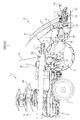
以下、図面に沿って、本発明の第1の実施の形態について説明する。図1に示すように、本実施の形態に係る乗用型のマルチ移植機100は、前輪1と後輪(車輪)2とによって支持される走行機体3を有し、走行機体3の後部には、昇降リンク機構5を介して植付作業機6が昇降自在に支持される。昇降リンク機構5は、走行機体3と植付作業機6との間に介設されたリフトシリンダ7を有し、後述する油圧コントロール機構25(図2参照)によるリフトシリンダ7の伸縮動作に応じて植付作業機6が昇降される。
<First Embodiment>
Hereinafter, a first embodiment of the present invention will be described with reference to the drawings. As shown in FIG. 1, the riding-type multi-transplanter 100 according to the present embodiment has a traveling machine body 3 supported by front wheels 1 and rear wheels (wheels) 2, and a rear part of the traveling machine body 3 has a traveling machine body 3. The planting work machine 6 is supported by the lifting link mechanism 5 so as to be lifted and lowered. The up-and-down link mechanism 5 has a lift cylinder 7 interposed between the traveling machine body 3 and the planting work machine 6, and responds to expansion and contraction of the lift cylinder 7 by a hydraulic control mechanism 25 (see FIG. 2) described later. The planting work machine 6 is moved up and down.

植付作業機6は、昇降リンク機構5によって支持される作業機フレーム8、マット苗が載置される苗載台9、芯に巻きつけられるロール状のシートを横架収納するシート収納部10、苗を圃場に植付ける植付機構11、圃場面を滑走する円筒状のローラフロート12並びに紙押さえロール13及びカッタレバー15の操作により圃場面を被覆したシートS(図5及び図10参照)とロール状のシートとを適宜分断するカッタ16等を備えて構成されている。 The planting work machine 6 includes a work machine frame 8 supported by the elevating and lowering link mechanism 5, a seedling stand 9 on which mat seedlings are placed, and a sheet storage section 10 for laterally storing roll-shaped sheets wound around a core. , A planting mechanism 11 for planting seedlings in a field, a cylindrical roller float 12 that slides in a field scene, a sheet S covering the field scene by operating a paper pressing roll 13 and a cutter lever 15 (see FIGS. 5 and 10) And a cutter 16 and the like for appropriately separating the roll-shaped sheet from each other.

植付機構11は、走行機体3の走行に伴い連続的に繰出されて圃場面を被覆するシートSの上からマット苗より掻取った苗を圃場に植付ける。ローラフロート12は、左右に延びる円筒状に形成されて前後に並列して設けられ、紙押さえロール13は、左右に延びる円筒状に形成されてローラフロート12より後方に配置される。ローラフロート12及び紙押さえロール13は、繰出されたシートSを圃場面に押圧しながら圃場面を滑走し、紙押さえロール13は、ローラフロート12より小さな接地面積となるように構成されている。 The planting mechanism 11 plants the seedlings scraped from the mat seedlings on the sheet S that is continuously fed out and covers the field scene as the traveling machine body 3 travels, in the field. The roller float 12 is formed in a cylindrical shape that extends in the left-right direction and is provided in parallel in the front-rear direction. The paper pressing roll 13 is formed in a cylindrical shape that extends in the left-right direction and is disposed behind the roller float 12. The roller float 12 and the paper pressing roll 13 slide in the field scene while pressing the fed-out sheet S against the field scene, and the paper pressing roll 13 has a smaller ground contact area than the roller float 12.

上記走行機体3の中央部には、オペレータが搭乗して走行機体3や植付作業機6を操作する運転部17が配置されている。該運転部17には運転座席19、ステアリングハンドル20、作業機操作具21(図7参照)、表示パネル22(図7参照)、植付距離設定手段84を有する入力パネル23(図7参照)等が配置されている。なお、本実施の形態では、特に記載が無い限りは運転座席19に着座したオペレータが向いている正面方向を前方とし、これを基準に前後左右方向を定義する。 At the center of the traveling machine body 3, an operation unit 17 is arranged in which an operator rides and operates the traveling machine body 3 and the planting work machine 6. The driver 17 has a driver's seat 19, a steering wheel 20, a work implement operation tool 21 (see FIG. 7), a display panel 22 (see FIG. 7), and an input panel 23 (see FIG. 7) having a planting distance setting means 84. Etc. are arranged. In the present embodiment, unless otherwise noted, the front direction facing the operator seated in the driver's seat 19 is defined as the front, and the front, rear, left, and right directions are defined on the basis of this.

走行機体3の前部にはエンジン(図示せず)やトランスミッション(図示せず)が搭載されている。エンジンが出力する動力は、トランスミッションで変速され、前輪1及び後輪2に伝達されると共に、油圧コントロール機構25(図2参照)を介して植付作業機6に伝達される。トランスミッションの内部には、植付クラッチ(作業機クラッチ、図示せず)が設けられており、該植付クラッチの断接に伴い植付作業機6への動力伝達が断接される。 An engine (not shown) and a transmission (not shown) are mounted on the front part of the traveling machine body 3. The power output from the engine is geared by the transmission, transmitted to the front wheels 1 and the rear wheels 2, and also transmitted to the work implement 6 with a plant via the hydraulic control mechanism 25 (see FIG. 2). A planting clutch (working machine clutch, not shown) is provided inside the transmission, and power transmission to the planting working machine 6 is connected/disconnected as the planting clutch is connected/disconnected.

ついで、油圧コントロール機構25について、図2に沿って説明する。油圧コントロール機構25は、作業機操作具21(図7参照)の操作により駆動する作業機操作カムモータ30と、作業機操作カムモータ30の駆動に基づいて回動する作業機操作カム31と、回動ピン33を中心に揺動し、作業機操作カム31の回動に伴い姿勢が変化するクラッチアーム35と、クラッチアーム35の姿勢変化に伴い開閉する油圧コントロールバルブ29と、作業機操作カム31の回動位置を検出する作業機操作カムポテンショ32と、を備える。 Next, the hydraulic control mechanism 25 will be described with reference to FIG. The hydraulic control mechanism 25 includes a work machine operation cam motor 30 driven by operation of the work machine operation tool 21 (see FIG. 7 ), a work machine operation cam 31 that rotates based on the drive of the work machine operation cam motor 30, and a rotation. A clutch arm 35 that swings around the pin 33 and whose posture changes with the rotation of the working machine operation cam 31, a hydraulic control valve 29 that opens and closes with a change in the posture of the clutch arm 35, and a working machine operation cam 31. And a work machine operation cam potentiometer 32 for detecting the rotational position.

作業機操作カム31は、上昇位置、固定位置、下降位置及び植付位置の各回動位置を有し、それぞれの回動位置は作業機操作カムポテンショ32により検出される。作業機操作カム31の各回動位置に従いクラッチアーム35が揺動して油圧コントロールバルブ29が開閉されると、トランスミッションに設けられた油圧ポンプ(図示せず)の油圧を開放又は遮断することによりリフトシリンダ7が伸縮して、植付作業機6が昇降する。また、植付作業機6の昇降高さは、昇降リンク機構5の角度に基づいてリフト角ポテンショ27(図8参照)により検出される。作業機操作カム31が上昇位置に位置する際には、植付作業機6が上昇し、固定位置に位置する際には、植付作業機6は任意の高さで固定され、下降位置に位置する際には、植付作業機6が下降する。作業機操作カム31が上昇位置に位置する際に、植付作業機6が所定高さ(上端位置)まで上昇したことをリフト角ポテンショ27により検出されると、作業機操作カム31が固定位置となり、植付作業機6の上昇は停止する。また、作業機操作カム31が下降位置に位置する際には、ローラフロート12が接地する高さまで植付作業機6が下降し、作業機操作カム31は植付位置へ移行可能となる。 The working machine operation cam 31 has a rotating position of a rising position, a fixed position, a descending position, and a planting position, and each rotating position is detected by the working machine operation cam potentiometer 32. When the clutch arm 35 swings and the hydraulic control valve 29 is opened/closed in accordance with each rotational position of the work machine operation cam 31, the hydraulic pump (not shown) provided in the transmission releases or cuts off the hydraulic pressure to lift the lift. The cylinder 7 expands and contracts, and the planting work machine 6 moves up and down. The lift height of the planting work machine 6 is detected by the lift angle potentiometer 27 (see FIG. 8) based on the angle of the lift link mechanism 5. When the working machine operation cam 31 is located in the raised position, the planting working machine 6 is raised, and when it is located in the fixed position, the planting working machine 6 is fixed at an arbitrary height and is placed in the lowered position. When positioned, the planting work machine 6 descends. When it is detected by the lift angle potentiometer 27 that the work implement 6 with plants is raised to a predetermined height (upper end position) when the work implement operation cam 31 is located at the raised position, the work implement operation cam 31 is at the fixed position. And the raising of the planting work machine 6 is stopped. Further, when the work implement operation cam 31 is located at the lowered position, the planting work implement 6 is lowered to a height at which the roller float 12 is in contact with the ground, and the work implement operation cam 31 can be moved to the planting position.

作業機操作カム31が下降位置及び植付位置に位置する状態かつローラフロート12が接地している状態においては、植付作業機6は、圃場面への追従に伴うローラフロート12の姿勢及び高さの変化に基づいて油圧コントロールバルブ29が開閉されて植付作業機6が自動的に昇降され、植付深さが一定に保たれる自動昇降状態となる。作業機操作カム31が植付位置以外に位置する際には植付クラッチは切断されて植付機構11は作動せず、植付位置に位置する際には植付クラッチが接続されて植付機構11が作動する。 When the work implement operation cam 31 is located at the lowered position and the planting position and the roller float 12 is in contact with the ground, the planting work implement 6 moves the posture and the height of the roller float 12 along with the tracking of the field scene. Based on the change in the height, the hydraulic control valve 29 is opened/closed to automatically move the planting work machine 6 up and down, and the planting depth is maintained in an automatic raising/lowering state. When the work machine operation cam 31 is located at a position other than the planting position, the planting clutch is disconnected and the planting mechanism 11 does not operate. When the work machine operation cam 31 is located at the planting position, the planting clutch is connected and planted. The mechanism 11 operates.

図3に示すように、エンジンで発生した動力は、前後に延びる入力軸36を介して、後輪2を支持するリヤアクスルケース37に伝達される。リヤアクスルケース37の内部には、入力軸36と一体的に回転する検出ギヤ41と、入力軸36の回転を制動する走行ブレーキ43と、が設けられている。入力軸36には、検出ギヤ41が固定されており、検出ギヤ41の回転量は、回転センサ42によって検出される。すなわち、検出ギヤ41と同量だけ回転する入力軸36の回転量は、検出ギヤ41及び回転センサ42によって構成される走行距離測定機構(走行距離測定手段)39によって検出され、この検出結果は制御部(制御手段、図8参照)40へ出力される。 As shown in FIG. 3, the power generated by the engine is transmitted to the rear axle case 37 supporting the rear wheel 2 via the input shaft 36 extending in the front-rear direction. Inside the rear axle case 37, a detection gear 41 that rotates integrally with the input shaft 36 and a traveling brake 43 that brakes the rotation of the input shaft 36 are provided. The detection gear 41 is fixed to the input shaft 36, and the rotation amount of the detection gear 41 is detected by the rotation sensor 42. That is, the rotation amount of the input shaft 36 that rotates by the same amount as the detection gear 41 is detected by the traveling distance measuring mechanism (driving distance measuring means) 39 configured by the detection gear 41 and the rotation sensor 42, and the detection result is controlled. It is output to the unit (control means, see FIG. 8) 40.

図4に示すように、シート収納部10は、左右端が開閉可能でロール状のシートを横架収納する紙ロールケース45と、作業機フレーム8に固定される検知機構支持片50と、シート収納部10からシートが繰出されているか否かを検出する紙切れ検知機構46と、を備える。紙切れ検知機構46は、板状に形成され、紙ロールケース45から繰出されたシートS(図5参照)に接触して揺動するシート検出片47と、シート検出片47の揺動を検出する紙切れ検出スイッチ49と、を備える。紙切れ検知機構46は、調整ボルト55によって検知機構支持片50に固定されており、調整ボルト55を締緩することにより、検知機構支持片50に設けられた長穴(図示せず)に沿って紙ロールケース45に対する紙切れ検知機構46の前後位置を変更できる。 As shown in FIG. 4, the sheet storage unit 10 includes a paper roll case 45 that can be opened and closed at the left and right ends and horizontally stores a roll-shaped sheet, a detection mechanism support piece 50 fixed to the work machine frame 8, and a sheet. A paper breakage detection mechanism 46 that detects whether or not a sheet is fed from the storage unit 10 is provided. The paper break detection mechanism 46 is formed in a plate shape, and detects a sheet detection piece 47 that swings in contact with the sheet S (see FIG. 5) fed from the paper roll case 45, and the swing of the sheet detection piece 47. A paper break detection switch 49 is provided. The paper break detection mechanism 46 is fixed to the detection mechanism support piece 50 by the adjustment bolt 55, and by tightening or loosening the adjustment bolt 55, the paper break detection mechanism 46 is moved along a long hole (not shown) provided in the detection mechanism support piece 50. The front-back position of the paper break detection mechanism 46 with respect to the paper roll case 45 can be changed.

シート検出片47は、紙ロールケース45に収納されたロール状のシートの中心軸より後方に配置された揺動軸51を中心として揺動可能に支持され、シート検出片47の下端がシートに接近する方向である前方へ向けて検出ばね52により付勢されている。紙ロールケース45に収納されているシートが紙ロールケース45から繰出されてシート検出片47と接触すると、シート検出片47の下端が検出ばね52の付勢力に抗して後方へ傾動する。紙切れ検出スイッチ49は、板状に形成されてシート検出片47に接触するスイッチレバー53を有しており、シート検出片47の傾動に伴ってスイッチレバー53の姿勢が変化すると、紙切れ検出スイッチ49のオンとオフとが切り替わる。そして、紙切れ検出スイッチ49は、シート収納部10からシートが繰出されている状態でオフとなり、シートが繰出されていない状態でオンとなる。 The sheet detection piece 47 is swingably supported around a swing shaft 51 arranged behind the central axis of the roll-shaped sheet stored in the paper roll case 45, and the lower end of the sheet detection piece 47 is placed on the sheet. It is biased by the detection spring 52 toward the front, which is the approaching direction. When the sheet stored in the paper roll case 45 is delivered from the paper roll case 45 and comes into contact with the sheet detection piece 47, the lower end of the sheet detection piece 47 tilts backward against the biasing force of the detection spring 52. The paper-out detection switch 49 includes a switch lever 53 formed in a plate shape and in contact with the sheet detection piece 47. When the posture of the switch lever 53 changes as the sheet detection piece 47 tilts, the paper-out detection switch 49. Is switched on and off. Then, the paper-out detection switch 49 is turned off when the sheet is being fed from the sheet storage unit 10 and is turned on when the sheet is not being fed.

紙ロールケース45に収納されたロール状のシートの中心軸とシート検出片47の下端との相対位置が適切でないときには、紙ロールケース45からシートが繰出されているにもかかわらず紙切れ検出スイッチ49がオンとなる場合や、シート検出片47が抵抗となってシートが適切に繰出されない場合等がある。この場合には、調整ボルト55の締緩によりシート検出片47の下端と調整ガイド56の隙間(A寸法)が適切な寸法となるように紙切れ検知機構46の位置を調整することにより、上記問題を解決することができる。 When the relative position between the central axis of the roll-shaped sheet accommodated in the paper roll case 45 and the lower end of the sheet detection piece 47 is not appropriate, the paper breakage detection switch 49 is used even if the sheet is fed from the paper roll case 45. May be turned on, the sheet detection piece 47 may become a resistance, and the sheet may not be properly fed. In this case, by adjusting the position of the paper break detection mechanism 46 so that the clearance (size A) between the lower end of the sheet detection piece 47 and the adjustment guide 56 becomes an appropriate size by tightening or loosening the adjustment bolt 55, the above problem occurs. Can be solved.

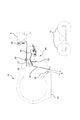
また、図5に示すように、シート収納部10は、紙ロールケース45の近傍から後方へ延出し、植付作業機6が上昇したときに紙ロールケース45から繰出されたシートSを支える紙ホルダ57と、揺動可能に支持されて紙ホルダ57を開閉操作する紙ホルダ操作レバー59と、回転させることにより紙ロールケース45に収納されているシートが回転して、シートを手動でシート収納部10の外部へ繰出すことが可能な紙繰出ノブ61と、を備える。 Further, as shown in FIG. 5, the sheet storage unit 10 extends rearward from the vicinity of the paper roll case 45 and supports the sheet S fed from the paper roll case 45 when the planting work machine 6 rises. The holder 57, the paper holder operating lever 59 that is swingably supported to open and close the paper holder 57, and the sheet stored in the paper roll case 45 are rotated by rotation, and the sheet is manually stored. A paper feeding knob 61 that can feed the paper to the outside of the unit 10.

紙ホルダ57は、移植作業を行うための閉鎖状態(図5(b))と、紙ロールケース45に収納されているシートを手動で繰出すことが可能な開放状態(図5(a))と、を有する。閉鎖状態において、紙ホルダ操作レバー59の先端を左側面視で時計回りに操作すると、紙ホルダ57の後端が下降して開放状態(図5(a))となる。紙ホルダ操作レバー59の先端を左側面視で反時計回りに操作すると、紙ホルダ57の後端が再び上昇して移植作業を行うための閉鎖状態(図5(b))となる。 The paper holder 57 is in a closed state (FIG. 5B) for carrying out the transplanting work and an open state in which the sheet stored in the paper roll case 45 can be manually fed out (FIG. 5A). And. When the front end of the paper holder operating lever 59 is operated clockwise in the left side view in the closed state, the rear end of the paper holder 57 descends to be in the open state (FIG. 5A). When the front end of the paper holder operating lever 59 is operated counterclockwise as viewed from the left side, the rear end of the paper holder 57 rises again to be in the closed state (FIG. 5(b)) for performing the transplanting work.

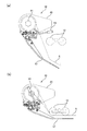
図6に示すように、走行機体3の左右両側には、紙ロールケース45に収納されているシートを使い切った際に使用するためのロール状の予備のシートPを支持可能な補助ロール台62が配置されている。補助ロール台62はロール状の予備のシートPの中心軸が略前後方向となるように予備のシートPを支持し、補助ロール台62に支持された予備のシートPの後端付近に設けられた上下方向の軸を中心に回動可能に構成されている。植付作業機6が上端位置にある場合において、補助ロール台62を回動すると、補助ロール台62に支持されたロール状の予備のシートPの端部が紙ロールケース45の端部と近接させることが可能に設けられている。 As shown in FIG. 6, on both left and right sides of the traveling machine body 3, an auxiliary roll base 62 capable of supporting a roll-shaped spare sheet P to be used when the sheets stored in the paper roll case 45 are used up. Are arranged. The auxiliary roll base 62 supports the auxiliary sheet P such that the central axis of the roll-shaped auxiliary sheet P is substantially in the front-rear direction, and is provided near the rear end of the auxiliary sheet P supported by the auxiliary roll base 62. It is configured to be rotatable about a vertical axis. When the planting work machine 6 is at the upper end position and the auxiliary roll base 62 is rotated, the end portion of the roll-shaped spare sheet P supported by the auxiliary roll base 62 comes close to the end portion of the paper roll case 45. It is possible to do.

図7に示すように、運転部17の前方には、表示パネル22が配置されており、その左後側に入力パネル23が配置され、表示パネル22の右後側には、植付作業機6を昇降するための作業機上操作スイッチ66及び作業機下操作スイッチ67を操作する作業機操作具21が配置されている。 As shown in FIG. 7, a display panel 22 is arranged in front of the operating unit 17, an input panel 23 is arranged on the left rear side thereof, and a planting work machine is arranged on the right rear side of the display panel 22. A work implement operating tool 21 for operating a work implement upper operation switch 66 and a work implement lower operation switch 67 for moving up and down 6 is arranged.

表示パネル22は、燃料の残量を表示する燃料表示ランプ69、シートの補給時期を報知する警報ランプ(報知手段)70、警報ランプ状態表示灯71及び警報ブザー状態表示灯72等を有する。警報ランプ70は、走行機体3に設けられた警報ブザー(報知手段、
図8参照)73と共に、制御部40から出力される信号を受けて作動し、警報ランプ70の点滅又は点灯や、警報ブザー73が発する音により、オペレータにシートの補給時期を報知するよう構成されている。
The display panel 22 has a fuel display lamp 69 for displaying the remaining amount of fuel, an alarm lamp (informing means) 70 for informing the sheet replenishment timing, an alarm lamp status display lamp 71, an alarm buzzer status display lamp 72, and the like. The alarm lamp 70 is an alarm buzzer (informing means, notifying unit) provided on the traveling body 3.
(See FIG. 8) 73, it is operated in response to a signal output from the control unit 40, and is configured to notify the operator of the sheet replenishment timing by blinking or lighting the alarm lamp 70 and a sound emitted by the alarm buzzer 73. ing.

入力パネル23は、後述する予備警報距離α(図9参照)を調節可能なタイミング調節ダイヤル75(調節手段)、シート収納部10に収納される使用前のシートの長さL1を入力するロール長設定ダイヤル(シート長入力手段)76、警報ランプ70並びに警報ブザー73による報知可否状態を切り替える予備警報モード切替プッシュスイッチ77、植付作業機6の駆動を規制し得る作業準備スイッチ79、警報ランプ70並びに警報ブザー73への信号の出力を停止する警報停止スイッチ80及び圃場を走行して移植作業を行う際の片道の植付距離L0を設定する植付距離設定手段84を有する。該植付距離設定手段84は、測定開始スイッチ81、測定終了スイッチ82、測定中表示ランプ83及び片道の植付距離L0を表示する表示部85を有する。 The input panel 23 includes a timing adjusting dial 75 (adjusting means) capable of adjusting a preliminary alarm distance α (see FIG. 9) described later, and a roll length for inputting a length L1 of a sheet stored in the sheet storage unit 10 before use. Preliminary alarm mode switching push switch 77 for switching the notification enable/disable state by the setting dial (sheet length input means) 76, the alarm lamp 70, and the alarm buzzer 73, the work preparation switch 79 capable of restricting the drive of the planted work machine 6, and the alarm lamp 70. Further, it has an alarm stop switch 80 for stopping the output of the signal to the alarm buzzer 73 and a planting distance setting means 84 for setting the one-way planting distance L0 when traveling in the field and performing the transplanting work. The planting distance setting means 84 has a measurement start switch 81, a measurement end switch 82, a measuring display lamp 83, and a display section 85 for displaying the one-way planting distance L0.

図8は、本形態における制御ブロック図を示しており、走行機体3は、各入出力に基づいて紙切れ警報制御(図9参照)を含む移植作業に使用する各装置の制御を行う制御部40を備えている。該制御部40は、CPU40a、ROM40b、RAM40c、インターフェース(I/F)40d等を含むマイクロコンピュータを備えている。制御部40の入力側には、作業準備スイッチ79、作業機上操作スイッチ66並びに作業機下操作スイッチ67、ロール長設定ダイヤル76、タイミング調節ダイヤル75、警報停止スイッチ80、作業機操作カムポテンショ32、リフト角ポテンショ27、紙切れ検出スイッチ49、予備警報モード切替プッシュスイッチ77、回転センサ42、測定開始スイッチ81及び測定終了スイッチ82等が接続されている。制御部40の出力側には、作業機操作カムモータ30、警報ランプ70、警報ブザー73、警報ランプ状態表示灯71、警報ブザー状態表示灯72、表示部85及び測定中表示ランプ83等が接続されている。制御部40は、紙切れ検知機構46により、シート収納部10からシートが繰出されていないことを検知したときに紙切れ警報の信号を出力して、警報ランプ70及び警報ブザー73を作動させる。 FIG. 8 shows a control block diagram in the present embodiment, and the traveling machine body 3 controls the respective devices used for the transplanting work including the paper break alarm control (see FIG. 9) based on each input/output. Equipped with. The control unit 40 includes a microcomputer including a CPU 40a, a ROM 40b, a RAM 40c, an interface (I/F) 40d, and the like. On the input side of the control unit 40, a work preparation switch 79, a work machine upper operation switch 66 and a work machine lower operation switch 67, a roll length setting dial 76, a timing adjustment dial 75, an alarm stop switch 80, a work machine operation cam potentiometer 32. The lift angle potentiometer 27, the paper break detection switch 49, the preliminary alarm mode switching push switch 77, the rotation sensor 42, the measurement start switch 81, the measurement end switch 82, and the like are connected. To the output side of the control unit 40, the work machine operation cam motor 30, the alarm lamp 70, the alarm buzzer 73, the alarm lamp status display lamp 71, the alarm buzzer status display lamp 72, the display section 85, the measuring display lamp 83, etc. are connected. ing. The control unit 40 outputs a paper-out alarm signal when the paper-out detection mechanism 46 detects that the sheet is not fed out from the sheet storage unit 10, and activates the alarm lamp 70 and the alarm buzzer 73.

ロール長設定ダイヤル76は、入力パネル23に向かって前後方向に進退可能で、入力パネル23から突出して設けられている。ロール長設定ダイヤル76は、押圧により入力パネル23の方向へ後退し、ロール長設定ダイヤル76が後退すると、入力パネル23の内部に設けられた予備警報モード切替プッシュスイッチ77が操作される。ロール長設定ダイヤル76の押圧力を解除すると、予備警報モード切替プッシュスイッチ77の内部に設けられた弾性体(図示せず)の反力により復帰する。 The roll length setting dial 76 can move forward and backward toward the input panel 23 and is provided so as to project from the input panel 23. The roll length setting dial 76 retracts toward the input panel 23 when pressed, and when the roll length setting dial 76 retracts, the preliminary alarm mode switching push switch 77 provided inside the input panel 23 is operated. When the pressing force of the roll length setting dial 76 is released, it is restored by the reaction force of the elastic body (not shown) provided inside the preliminary alarm mode switching push switch 77.

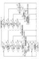
ついで、紙切れ警報制御について、図9及び図10に沿って説明する。また、本フローは、予備警報モード又は非予備警報モードのみのフローを示すが、後述する予備警報ランプモード又は予備警報ブザーモードのフローは、予備警報モードと同様のフロー(ステップS15のYES)となり、その説明は省略する。紙切れ警報制御が開始されると(ステップS1)、制御部40は、作業準備スイッチ79がオンであるか否かを判断して(ステップS11)、オフの場合には処理をステップS1に戻し、オンの場合には、警報停止フラグがセットされているか否かを判断する(ステップS12)。制御部40は、警報停止フラグがセットされていない場合、警報停止スイッチ80の操作があるか否かを判断し(ステップS13)、操作がない場合、紙切れ検出スイッチ49によりシート収納部10からシートが繰出されているか否かを判断する(ステップS14)。 Next, the paper shortage alarm control will be described with reference to FIGS. 9 and 10. Further, this flow shows only the preliminary warning mode or the non-preliminary warning mode, but the flow of the preliminary warning lamp mode or the preliminary warning buzzer mode described later is the same as the preliminary warning mode (YES in step S15). , The description is omitted. When the paper-out warning control is started (step S1), the control unit 40 determines whether or not the work preparation switch 79 is on (step S11), and when it is off, returns the process to step S1. If it is on, it is determined whether or not the alarm stop flag is set (step S12). When the alarm stop flag is not set, the control unit 40 determines whether or not the alarm stop switch 80 has been operated (step S13). When the alarm stop switch 80 has not been operated, the sheet breakage detection switch 49 causes the sheet storage unit 10 to move the sheet. Is determined (step S14).

制御部40は、シート収納部からシートが繰出されており紙切れ検出スイッチ49がオフの場合、予備警報モードであるか否かを判断する(ステップS15)。予備警報モード切替プッシュスイッチ77の操作により、制御部40は予備警報モード→予備警報ランプモード→予備警報ブザーモード→非予備警報モード→予備警報モード→・・・と順次切り替えられる。予備警報モードでは警報ランプ70及び警報ブザー73が共に作動可能で、予備警報ランプモードでは警報ランプ70のみ作動可能で、予備警報ブザーモードでは警報ブザー73のみ作動可能で、非予備警報モードでは警報ランプ70又は警報ブザー73の何れも作動しない。制御部40が予備警報の信号を警報ランプ70に出力し得る状態である場合には警報ランプ状態表示灯71が点灯し、制御部40が予備警報の信号を警報ブザー73に出力し得る状態である場合には警報ブザー状態表示灯72が点灯する。 When the sheet is fed from the sheet storage unit and the paper-out detection switch 49 is off, the control unit 40 determines whether or not the preliminary alarm mode is set (step S15). By operating the preliminary alarm mode switching push switch 77, the control unit 40 is sequentially switched to the preliminary alarm mode→the preliminary alarm lamp mode→the preliminary alarm buzzer mode→the non-preliminary alarm mode→the preliminary alarm mode→. Both the alarm lamp 70 and the alarm buzzer 73 can be activated in the preliminary alarm mode, only the alarm lamp 70 can be activated in the preliminary alarm lamp mode, only the alarm buzzer 73 can be activated in the preliminary alarm buzzer mode, and the alarm lamp in the non-preliminary alarm mode. Neither 70 nor the alarm buzzer 73 is activated. When the control unit 40 is in a state where it can output a preliminary warning signal to the warning lamp 70, the warning lamp status display lamp 71 lights up, and the control unit 40 can output a preliminary warning signal to the warning buzzer 73. In some cases, the alarm buzzer status indicator lamp 72 lights up.

制御部40は、予備警報モードでない場合(ステップS15のNO)には処理をステップS1に戻し、予備警報モードである場合(ステップS15のYES)には、植付距離設定手段84による片道の植付距離L0の設定操作の有無を判断する(ステップS29)。ここで、片道の植付距離L0の設定方法について説明する。オペレータは、予備警報モード切替プッシュスイッチ77を操作して予備警報モードをオンにした状態で、測定開始位置である圃場端にマルチ移植機100を停止させる。この状態において、オペレータが測定開始スイッチ81を押すと(ステップS29のYES)、制御部40は新たな片道の植付距離L0の測定を開始する。片道の植付距離L0の測定中は測定中表示ランプ83が点灯し、測定開始スイッチ81が押されてから入力軸36の回転を検出する走行距離測定機構39の検知結果に基づいて測定された走行機体3の走行距離が表示部85に点滅表示される。マルチ移植機100が圃場の片道の植付を行う距離を走行して、測定終了位置である他の圃場端に到達した時に、オペレータが測定終了スイッチ82を押すと、測定開始スイッチ81が押されてから測定終了スイッチ82が押されるまでの走行機体3の走行距離が新たな片道の植付距離L0として設定されて制御部40に記憶されると共に、表示部85に表示されている片道の植付距離L0は点滅表示から点灯表示へ切り替わり、片道の植付距離L0の設定が終了し(ステップS30)、処理がステップS1に戻る。 The control part 40 returns a process to step S1 when it is not a preliminary warning mode (NO of step S15), and when it is a preliminary warning mode (YES of step S15), one-way planting by the planting distance setting means 84. Whether or not the setting operation of the attached distance L0 is performed is determined (step S29). Here, a method of setting the one-way planting distance L0 will be described. The operator operates the preliminary alarm mode selection push switch 77 to turn on the preliminary alarm mode, and stops the multi-transplanter 100 at the field end, which is the measurement start position. In this state, when the operator presses the measurement start switch 81 (YES in step S29), the control unit 40 starts measuring a new one-way planting distance L0. During the measurement of the one-way planting distance L0, the in-measuring display lamp 83 lights up, and the measurement is performed based on the detection result of the traveling distance measuring mechanism 39 that detects the rotation of the input shaft 36 after the measurement start switch 81 is pressed. The traveling distance of the traveling machine body 3 is displayed blinking on the display unit 85. When the multi-transplanter 100 travels a distance for one-way planting in the field and reaches another field end which is the measurement end position, when the operator presses the measurement end switch 82, the measurement start switch 81 is pressed. The distance traveled by the traveling machine body 3 from when the measurement end switch 82 is pressed is set as a new one-way planting distance L0 and stored in the control unit 40, and the one-way planting displayed on the display unit 85 is performed. The attached distance L0 is switched from the blinking display to the lit display, the setting of the one-way planting distance L0 is completed (step S30), and the process returns to step S1.

制御部40は、植付距離設定手段84による片道の植付距離L0の設定操作が無い場合(ステップS29のNO)、ロール長設定ダイヤル76の回転操作の有無を判断する(ステップS16)。オペレータが、ロール長設定ダイヤル76を回転させて(ステップS16のYES)、市販されているシートの規定長さの100(m)、125(m)及び170(m)の3つの長さから1つの長さを選択すると、制御部40は、選択された長さを新たなシートの長さL1として制御部40に記憶し(ステップS17)、処理をステップS1に戻す。 When the one-way planting distance L0 is not set by the planting distance setting means 84 (NO in step S29), the control unit 40 determines whether or not the roll length setting dial 76 is rotated (step S16). The operator rotates the roll length setting dial 76 (YES in step S16) to select one of the three commercially available sheet lengths of 100 (m), 125 (m) and 170 (m). When one length is selected, the control unit 40 stores the selected length as a new sheet length L1 in the control unit 40 (step S17), and returns the process to step S1.

ロール長設定ダイヤル76の回転操作がない場合(ステップS16のNO)、制御部40は、タイミング調節ダイヤル75の操作の有無を判断する(ステップS18)。オペレータがタイミング調節ダイヤル75を操作すると(ステップS18のYES)、制御部40は、タイミング調節ダイヤル75の回動角度に対応した予備警報距離αを記憶し(ステップS19)、処理をステップS1に戻す。具体的には、オペレータがタイミング調節ダイヤル75を反時計回りに回し切ると、予備警報距離αが0(m)となり、時計回りに回すと回動させた角度に従って徐々に予備警報距離αが大きくなり、0(m)〜30(m)の間で予備警報距離αの調節が可能となっている。 When the roll length setting dial 76 is not rotated (NO in step S16), the control unit 40 determines whether or not the timing adjustment dial 75 is operated (step S18). When the operator operates the timing adjustment dial 75 (YES in step S18), the control unit 40 stores the preliminary warning distance α corresponding to the rotation angle of the timing adjustment dial 75 (step S19), and returns the process to step S1. .. Specifically, when the operator fully turns the timing adjustment dial 75 counterclockwise, the preliminary warning distance α becomes 0 (m), and when it is turned clockwise, the preliminary warning distance α gradually increases in accordance with the rotated angle. Therefore, the preliminary warning distance α can be adjusted between 0 (m) and 30 (m).

なお、通常、オペレータは、シートを繰り出しつつ移植作業を行うマルチ移植作業の開始前に、上述した片道の植付距離L0、シートの長さL1及び予備警報距離αの設定操作を行う。 Note that, usually, before the start of the multi-transplanting work in which the transplanting work is performed while the sheet is being fed out, the operator performs the setting operation of the one-way planting distance L0, the sheet length L1 and the preliminary warning distance α.

制御部40は、タイミング調節ダイヤル75の操作がない場合(ステップ18のNO)、植付作業機6の自動昇降状態であるか否かを判断し(ステップS20)、自動昇降状態である場合(ステップS20のYES)、走行距離の測定を開始して、測定結果を総走行距離Lに加算する(ステップS22)。制御部40は、植付作業機6の自動昇降状態でない場合は(ステップS20のNO)、作業機操作カム31が植付位置(植付クラッチが接続状態)であるか否かを判断して(ステップS21)、植付位置でない場合は処理をステップS1に戻し、植付位置である場合は、ステップS20で自動昇降状態である場合と同様に、走行距離の測定を開始して、測定結果を総走行距離Lに加算する(ステップS22)。そして、制御部40は、総走行距離Lと、片道の植付距離L0の2倍の長さとして算出される往復の植付距離(L0×2)と予備警報距離αとをシートの長さL1から減算した報知距離(L1−L0×2−α)と、を比較する(ステップS23)。制御部40は、報知距離(L1−L0×2−α)が総走行距離Lよりも大きい場合には(ステップS23のNO)、処理をステップS1に戻す。総走行距離Lと報知距離(L1−L0×2−α)が等しくなった際には(ステップS23のYES)、制御部40は、警報ランプ70及び警報ブザー73を作動させる予備警報の信号の出力を開始し(ステップS24)、処理をステップS1に戻す。すなわち、制御部40は、総走行距離Lが、シート収納部10に収納される使用前のシートの長さL1と往復の植付距離(L0×2)との差より、予備警報距離αだけ短い距離となった時に予備警報の信号の出力を開始する。 When the timing adjusting dial 75 is not operated (NO in step 18), the control unit 40 determines whether or not the planting work machine 6 is in the automatic raising/lowering state (step S20), and in the automatic raising/lowering state ( If YES in step S20), the measurement of the travel distance is started, and the measurement result is added to the total travel distance L (step S22). When the planting work machine 6 is not in the automatic raising/lowering state (NO in step S20), the control unit 40 determines whether or not the work machine operating cam 31 is in the planting position (the planting clutch is in the connected state). (Step S21), if it is not the planting position, the process is returned to step S1, and if it is the planting position, measurement of the traveling distance is started in the same way as in the case of the automatic elevating state in step S20, and the measurement result Is added to the total traveling distance L (step S22). Then, the control unit 40 sets the total travel distance L, the reciprocating planting distance (L0×2) calculated as a length twice the one-way planting distance L0, and the preliminary warning distance α to the seat length. The notification distance (L1-L0×2-α) subtracted from L1 is compared (step S23). When the notification distance (L1-L0×2-α) is larger than the total travel distance L (NO in step S23), the control unit 40 returns the process to step S1. When the total travel distance L and the notification distance (L1-L0×2-α) become equal (YES in step S23), the control unit 40 sends a signal of a preliminary alarm that activates the alarm lamp 70 and the alarm buzzer 73. The output is started (step S24), and the process is returned to step S1. That is, the control unit 40 determines that the total travel distance L is equal to the preliminary warning distance α based on the difference between the length L1 of the sheet before use stored in the sheet storage unit 10 and the reciprocating planting distance (L0×2). When the distance becomes short, the output of the preliminary warning signal is started.

ステップS14にてシート収納部10からシートが繰出されておらず紙切れ検出スイッチ49がオンである場合、制御部40は予備警報の信号の出力を停止し、警報ランプ70及び警報ブザー73へ紙切れ警報の信号の出力を開始して、制御部40に積算して記憶された総走行距離Lを0(m)に書き換える(ステップS25)。これにより、総走行距離Lの新たな積算が開始可能な状態となり、制御部40は処理をステップS1に戻す。 In step S14, when the sheet is not fed out from the sheet storage unit 10 and the paper-out detection switch 49 is on, the control unit 40 stops the output of the signal of the preliminary alarm, and the alarm lamp 70 and the alarm buzzer 73 are notified of the paper-out alarm. The output of the signal is started, and the total traveling distance L accumulated and stored in the control unit 40 is rewritten to 0 (m) (step S25). As a result, a new integration of the total travel distance L can be started, and the control unit 40 returns the process to step S1.

図11に示す通り、制御部40から予備警報の信号が出力されると、警報ランプ70が点滅すると共に、警報ブザー73が断続音を発する。予備警報が開始されてから、制御部40から紙切れ警報の信号が出力されるまでは、マルチ移植機100が進むにつれてランプの点滅の間隔と断続音の間隔が小さくなる。また、制御部40から紙切れ警報の信号が出力されると、警報ランプ70は連続点灯し、警報ブザー73は連続音を発する。 As shown in FIG. 11, when the signal of the preliminary alarm is output from the control unit 40, the alarm lamp 70 blinks and the alarm buzzer 73 emits an intermittent sound. From the start of the preliminary warning until the output of the paper-out warning signal from the control unit 40, the interval of blinking of the lamp and the interval of intermittent sound become smaller as the multi-transplanter 100 advances. Further, when the control unit 40 outputs a signal for a paper out alarm, the alarm lamp 70 is continuously turned on and the alarm buzzer 73 emits a continuous sound.

ステップS13にて警報停止スイッチ80の操作がある場合、制御部40は予備警報及び紙切れ警報の信号の出力を停止し、警報停止フラグをセットし(ステップS26)、処理をステップS1に戻す。制御部40は、ステップS12にて警報停止フラグがセットされている場合、一度植付作業機6を上端位置まで上昇した後で所定高さ、例えばローラフロート12が接地する高さまで下降した時に(ステップS27)警報停止フラグを解除し(ステップS28)、処理をステップS1に戻す。これにより、制御部40は、再び予備警報又は紙切れ警報の信号を出力可能な状態となる。また、片道の植付距離L0の設定操作及び総走行距離Lの積算が一度も行われていない状態においては、片道の植付距離L0及び総走行距離Lのいずれも制御部40に0(m)として記憶されており、ロール長設定ダイヤル76の操作が一度も行われていない状態においては、シートの長さL1は100(m)に設定されている。なお、片道の植付距離L0の設定操作及びロール長設定ダイヤル76の設定操作が一度も行われていない状態において予備警報モードに設定された場合、制御部40は、表示部85に片道の植付距離L0及びシートの長さL1の初期設定を促すメッセージを表示させ、片道の植付距離L0及びシートの長さL1の初期設定がなされるまでは予備警報の信号の出力を禁止する制御を行ってもよい。 When the alarm stop switch 80 is operated in step S13, the control unit 40 stops the output of the preliminary alarm signal and the paper shortage alarm signal, sets the alarm stop flag (step S26), and returns the process to step S1. When the alarm stop flag is set in step S12, the control unit 40 once raises the work implement 6 with the plant to the upper end position, and then descends to a predetermined height, for example, the height at which the roller float 12 comes into contact with the ground ( (Step S27) The alarm stop flag is cleared (step S28), and the process is returned to step S1. As a result, the control unit 40 becomes ready to output the preliminary warning signal or the paper-out warning signal again. Further, when the setting operation of the one-way planting distance L0 and the integration of the total traveling distance L have never been performed, both the one-way planting distance L0 and the total traveling distance L are 0 (m). ), and the sheet length L1 is set to 100 (m) in a state where the roll length setting dial 76 has never been operated. In addition, when the preliminary alarm mode is set in a state where the setting operation of the one-way planting distance L0 and the setting operation of the roll length setting dial 76 have never been performed, the control unit 40 causes the display unit 85 to display the one-way planting distance. A message that prompts the initial setting of the attachment distance L0 and the seat length L1 is displayed, and the control that prohibits the output of the preliminary warning signal is performed until the one-way planting distance L0 and the seat length L1 are initialized. You can go.

紙切れ警報制御によって警報ランプ70及び警報ブザー73によってシート収納部10に収納されているシートの残り長さが少ないことを報知されたオペレータは、例えばシート収納部10にシートを補給する。この場合、事前に補助ロール台62又はマルチ移植機100の外に準備しておいた予備のシートPが使用される。オペレータは、補助ロール台62に支持された予備のシートPを使用する場合、まずは植付作業機6を上端位置まで上昇させ、紙ホルダ操作レバー59を操作して紙ホルダ57を開放状態とする。これにより、紙ホルダ57が邪魔にならず紙ロールケース45に収納されているシートを繰出し易くなる。次いで、オペレータは、紙ロールケース45の右端又は左端を開放し、紙ロールケース45の内部に残っているシートや芯等を搬出して紙ロールケース45の内部を空にする。オペレータは、この状態で、補助ロール台62に支持された予備のシートPを補助ロール台62ごと回動させ、予備のシートPの端部と紙ロールケース45の端部を近接させて、予備のシートPを空になった紙ロールケース45の内部に搬入することにより、補助ロール台62のシートを紙ロールケース45の内部に補給することができる。その後、オペレータは、紙ロールケース45の右端及び左端を閉鎖し、紙繰出ノブ61を回転させて紙ロールケース45から十分な長さのシートSを繰出す。該十分な長さとは、前後のローラフロート12が接地した際に少なくとも前方のローラフロート12の接地部分より後方まで延出する長さをいう。オペレータは、シートを手動で繰出した後、紙ホルダ操作レバー59を操作して紙ホルダを閉鎖状態とし、繰出されたシートSをローラフロート12と紙ホルダ57で挟むように保持することで、シート収納部10へシートの補給が完了する。 The operator is informed that the remaining length of the sheet stored in the sheet storage unit 10 is short by the alarm lamp 70 and the alarm buzzer 73 by the paper shortage alarm control, and supplies the sheet to the sheet storage unit 10, for example. In this case, the auxiliary sheet P prepared in advance outside the auxiliary roll base 62 or the multi-transplanter 100 is used. When using the auxiliary sheet P supported by the auxiliary roll base 62, the operator first raises the planting work machine 6 to the upper end position and operates the paper holder operating lever 59 to open the paper holder 57. .. As a result, the sheet holder 57 does not get in the way and the sheet stored in the paper roll case 45 can be easily fed out. Next, the operator opens the right end or the left end of the paper roll case 45, and carries out the sheets, cores and the like remaining inside the paper roll case 45 to empty the inside of the paper roll case 45. In this state, the operator rotates the auxiliary sheet P supported by the auxiliary roll base 62 together with the auxiliary roll base 62 to bring the end portion of the auxiliary sheet P and the end portion of the paper roll case 45 into close proximity to each other. By carrying the sheet P of No. 2 into the empty paper roll case 45, the sheet of the auxiliary roll base 62 can be replenished into the paper roll case 45. After that, the operator closes the right end and the left end of the paper roll case 45 and rotates the paper feeding knob 61 to feed the sheet S of a sufficient length from the paper roll case 45. The sufficient length means a length which extends at least to the rear from the ground contact portion of the front roller float 12 when the front and rear roller floats 12 are grounded. The operator manually feeds the sheet, then operates the paper holder operating lever 59 to close the paper holder, and holds the fed sheet S so as to be sandwiched between the roller float 12 and the paper holder 57. The replenishment of the sheets to the storage unit 10 is completed.

以上より、本実施の形態は、入力軸36の回転量に基づいて算出した植付作業機6がシートを敷ける状態における総走行距離Lをシートの使用長さとみなし、該シートの使用長さがシート収納部10に収納される使用前のシートの長さL1から往復の植付距離(L0×2)を減算した長さに達したとき又は更に予備警報距離αだけ減算された長さに達した際に、オペレータに報知できる。これにより、オペレータはシートの残り長さが次の1往復の植付距離L0の分よりも少ないことを知ることができる。このため、オペレータは、次に移植作業の起点となる一方の圃場端に到着した際にシート収納部10に収納されているシートを交換することで、シートを効率よく使用しつつ速やかにシートの交換作業を済ますことができ、効率よく移植作業を行うことができる。また、上記一方の圃場端にのみ予備のシートPを準備しておけばよいので、予備のシートPの運び出し作業を簡便にできる。更に、シートを使い切りたい場合には、オペレータは警報ランプ70及び警報ブザー73が作動した後に上記一方の圃場端へ達した際に一つの予備のシートPのみを補助ロール台62に搭載して作業を続行することで、予備のシートPを搭載した状態での移植作業の距離を短くすることができ、移植作業精度の低下、圃場へのマルチ移植機100の沈み込みの増大及び走行時の燃費低下等を低減することができる。 As described above, in the present embodiment, the total travel distance L in the state in which the planting work machine 6 can spread the sheet, which is calculated based on the rotation amount of the input shaft 36, is regarded as the sheet use length, and the sheet use length is used. Has reached the length obtained by subtracting the reciprocating planting distance (L0×2) from the length L1 of the sheet before use stored in the sheet storage unit 10 or the length obtained by further subtracting the preliminary warning distance α. When it reaches, it can notify the operator. Thereby, the operator can know that the remaining length of the sheet is less than the planting distance L0 of one round trip. Therefore, the operator replaces the sheet stored in the sheet storage unit 10 when the operator arrives at one end of the field, which is the starting point of the transplanting work, so that the sheet can be used efficiently and quickly. The replacement work can be completed, and the transplant work can be performed efficiently. Further, since it is sufficient to prepare the spare sheet P only at the end of the one field, the work of carrying out the spare sheet P can be simplified. Further, when the operator wants to use up the sheet, the operator mounts only one spare sheet P on the auxiliary roll base 62 when the one of the fields ends after the alarm lamp 70 and the alarm buzzer 73 are activated. By continuing the above, it is possible to shorten the distance of the transplanting work in the state where the spare sheet P is mounted, the accuracy of the transplanting work is reduced, the sinking of the multi-transplanter 100 into the field is increased, and the fuel consumption during traveling is reduced. It is possible to reduce the deterioration.

オペレータが圃場長測定開始スイッチ81を押してから測定終了スイッチ82を押すまでの走行機体3が走行する距離を片道の植付距離L0として設定するよう構成したので、オペレータは片道の植付距離L0を簡単に測定することができ、利便性を向上できる。また、片道の植付距離L0の測定には走行距離測定手段39を使用しているので、新たな測定手段を設ける必要が無く、コストダウンできる。片道の植付距離L0の測定中は、表示部85に表示された長さが測定開始スイッチ81を押した以降の走行距離に基づいて増加し、測定中表示ランプ83が点灯するので、オペレータが片道の植付距離L0の測定中であることを容易に認識できる。なお、表示部85の表示は数字で表しても良いし、棒グラフ等で表示しても良い。また、オペレータに対する片道の植付距離L0の測定中であることの表示は、上記方法に限られず、測定中表示ランプ83の点滅によって行っても良いし、ブザー等による音や、これらの組み合わせによって行っても良い。 Since the operator sets the distance traveled by the traveling machine body 3 from pressing the field length measurement start switch 81 to pressing the measurement end switch 82 as the one-way planting distance L0, the operator sets the one-way planting distance L0. It can be easily measured and the convenience can be improved. Further, since the traveling distance measuring means 39 is used to measure the one-way planting distance L0, it is not necessary to provide a new measuring means, and the cost can be reduced. During the measurement of the one-way planting distance L0, the length displayed on the display unit 85 increases based on the traveled distance after the measurement start switch 81 is pressed, and the in-measuring display lamp 83 lights up. It can be easily recognized that the one-way planting distance L0 is being measured. The display of the display unit 85 may be represented by a number, a bar graph, or the like. The indication that the one-way planting distance L0 is being measured to the operator is not limited to the above method, and may be performed by blinking the measuring display lamp 83, or by a sound such as a buzzer or a combination thereof. You can go.

なお、報知距離(L1−L0×2−α)に含まれる往復の植付距離(L0×2)は、片道の植付距離L0と置き換えても良い。このように置き換えた報知距離(L1−L0−α)を設定する場合は、往復走行を行う圃場の両端でシートの補給が行えるように圃場の両端に予備のシートPを備えることにより、予備のシートPを搭載した状態での移植作業の距離を短くすることができる。また、上記往復の植付距離(L0×2)の設定するにあたり、片道の植付距離L0の2倍の距離として算出する代わりに、実際に圃場を往復走行した走行距離の測定結果を用いても、結果が何ら変わるものではない。また、片道の植付距離L0の設定操作(ステップS29、ステップS30)は、紙切れ警報制御の一部として構成したが、紙切れ警報制御と独立した制御としてもよい。この場合は、移植作業を行いながら片道の植付距離L0の測定を行うことができ、作業時間を短縮できる。 The round-trip planting distance (L0×2) included in the notification distance (L1-L0×2-α) may be replaced with the one-way planting distance L0. When the notification distance (L1-L0-α) thus replaced is set, the spare sheets P are provided at both ends of the field so that the sheets can be replenished at both ends of the field where the vehicle travels back and forth. It is possible to shorten the distance of the transplanting work with the sheet P mounted. Further, in setting the above-mentioned reciprocating planting distance (L0×2), instead of calculating as a distance twice as long as the one-way planting distance L0, the measurement result of the traveling distance actually traveled back and forth in the field is used. However, the result does not change at all. Further, the setting operation of the one-way planting distance L0 (step S29, step S30) is configured as a part of the paper-out alarm control, but may be a control independent of the paper-out alarm control. In this case, the one-way planting distance L0 can be measured while performing the transplanting work, and the working time can be shortened.

植付作業機6の自動昇降状態であるときの総走行距離Lに基づいて制御部40が予備警報の信号を出力する場合は、移植作業を行わずにシートの被覆作業を行う際においてもシートの使用長さの算出を行うことができる。また、本実施の形態では、後輪2の回転に伴って回転する入力軸36の回転量を検出することにより、後輪2の回転量を間接的に検出したが、走行距離の算出にあたっては当然ながら前輪1又は後輪2の回転量を直接的に検出しても良いし、前輪1又は後輪2の回転に伴って回転する入力軸36以外の部材の回転量を検出してもよい。 When the control unit 40 outputs the signal of the preliminary warning based on the total traveling distance L when the work machine 6 with the plant is in the automatic raising/lowering state, the sheet is covered even when the covering work of the sheet is carried out without carrying out the transplant work. It is possible to calculate the used length of. Further, in the present embodiment, the rotation amount of the rear wheel 2 is indirectly detected by detecting the rotation amount of the input shaft 36 that rotates with the rotation of the rear wheel 2. However, in calculating the traveling distance, Of course, the amount of rotation of the front wheel 1 or the rear wheel 2 may be directly detected, or the amount of rotation of a member other than the input shaft 36 that rotates with the rotation of the front wheel 1 or the rear wheel 2 may be detected. ..

制御部40は、シート収納部10からシートが繰出されていることを検知しなくなった際に、積算して記憶した総走行距離Lを0(m)に書き換えるので、オペレータがシートの補給後における総走行距離Lの初期化操作を行う手間を省くと共に、オペレータが初期化操作を行い忘れてシートの残り長さが分からなくなるということを防止することができる。また、上記総走行距離Lを0(m)に書き換える契機として紙切れ検出スイッチ49のオン信号を使用したので、別途の検出手段や入力手段等を必要とせず、部品点数の削減によりコストダウンできる。 Since the control unit 40 rewrites the accumulated and stored total travel distance L to 0 (m) when it no longer detects that the sheet is being fed out from the sheet storage unit 10, the operator can replenish the sheet after the sheet is replenished. It is possible to save the trouble of initializing the total traveling distance L and prevent the operator from forgetting to perform the initializing operation and not knowing the remaining length of the sheet. Further, since the ON signal of the paper break detection switch 49 is used as a trigger for rewriting the total travel distance L to 0 (m), no additional detection means or input means is required, and the cost can be reduced by reducing the number of parts.

また、オペレータが予備警報距離αをタイミング調節ダイヤル75で調節可能としたことにより、後輪2のスリップその他の理由により制御部40が積算した総走行距離Lと実際のシートの使用長さとに発生し得る差異を考慮した報知時期の調整や、オペレータが好みにより報知時期を調節可能となるので、利便性を向上できる。 Further, since the operator can adjust the preliminary warning distance α with the timing adjustment dial 75, the total traveling distance L accumulated by the control unit 40 due to slip of the rear wheel 2 and other reasons and the actual used seat length are generated. Since it is possible to adjust the notification time in consideration of possible differences and the operator can adjust the notification time according to his/her preference, convenience can be improved.

シート収納部10に収納されるシートの長さL1の入力に際し、予め定められた3つの長さの中からオペレータが1つの長さを選択可能としたので、規格等により定められた未使用のシートの複数の長さを予め記憶させておくことで、シートの長さL1を直接的に数値入力する場合と比べて、ロール長設定ダイヤル76によるシートの長さL1を入力するオペレータの手間を省くと共に、数値の入力ミスを減らすことができる。なお、シートの長さL1の入力手段は、上記3つの長さの中から選択する構成に限らず、2つの長さから選択する構成でも3つより多い長さの中から選択する構成でも構わないことは言うまでもないが、無段階的に長さを入力する構成としても良い。例えば、オペレータがロール長設定ダイヤル76を入力パネル23に向かって時計回りに回転させると、回転した角度に基づいて入力されるシートの長さL1の値が無段階的に拡大し、反時計回りに回すと、回転した角度に基づいて入力されるシートの長さL1の値が無段階的に減少するような構成が考えられる。この場合は入力されたシートの長さL1の値をドットマトリクスや7セグメント表示機等によりデジタル的に表示する表示装置を表示パネル22に設けると、入力されたシートの長さL1の視認性を向上できる。 When the length L1 of the sheet stored in the sheet storage unit 10 is input, the operator can select one length from the three predetermined lengths, so that the unused length specified by the standard or the like is not used. By storing a plurality of sheet lengths in advance, compared with a case where the sheet length L1 is directly input as a numerical value, the operator's labor for inputting the sheet length L1 by the roll length setting dial 76 is saved. Not only can it be omitted, but input mistakes in numerical values can be reduced. The input means for the sheet length L1 is not limited to the configuration of selecting from the above three lengths, and the configuration of selecting from two lengths or the configuration of selecting from more than three lengths may be used. Needless to say, the length may be input steplessly. For example, when the operator rotates the roll length setting dial 76 clockwise toward the input panel 23, the value of the sheet length L1 input based on the rotated angle is increased steplessly and counterclockwise. It is conceivable that the value of the sheet length L1 input based on the rotated angle will be reduced steplessly when turned to. In this case, if the display panel 22 is provided with a display device that digitally displays the value of the input sheet length L1 by a dot matrix or a 7-segment display, the visibility of the input sheet length L1 is improved. Can be improved.

オペレータがロール長設定ダイヤル76と予備警報モード切替プッシュスイッチ77を一つの入力装置で操作可能に構成したので、操作の際にオペレータが入力装置を探す手間を省き、部品点数の削減によりコストダウンできる。制御部40は、予備警報の信号を総走行距離Lと報知距離(L1−α)との差の減少に伴って、警報ランプ70の点滅や警報ブザー73の断続音を徐々に間隔が短くなるように変化させて出力し、紙切れ警報の信号を、警報ランプ70の点灯や警報ブザー73の連続音として出力するので、シート収納部10に収納されているシートの残り長さが徐々に短くなっていく様子や該シートを使い切ったことをオペレータが感覚的に理解しやすい。なお、予備警報又は紙切れ警報の信号が出力されたことによるオペレータへの報知は、運転座席19やステアリングハンドル20等を振動させることによって行っても良い。この場合は、移植作業中に周囲の騒音が大きい場合でも、オペレータが警報に気づきやすくすることができる。なお、制御部40はディスクリート回路により形成されていてもよいし、半導体集積回路素子として一体に形成されていてもよい。 Since the operator can operate the roll length setting dial 76 and the preliminary alarm mode switching push switch 77 with one input device, the operator does not have to search for the input device at the time of operation and the cost can be reduced by reducing the number of parts. .. The control unit 40 gradually shortens the interval of the flashing alarm lamp 70 and the intermittent buzzer sound of the alarm buzzer 73 as the difference between the total travel distance L and the notification distance (L1-α) of the preliminary warning signal decreases. And outputs the signal of the paper shortage alarm as the lighting of the alarm lamp 70 and the continuous sound of the alarm buzzer 73, the remaining length of the sheets stored in the sheet storage unit 10 gradually decreases. It is easy for the operator to intuitively understand how the sheet is going to be used and the sheet has been used up. It should be noted that the notification to the operator when the signal of the preliminary warning or the paper shortage warning is output may be performed by vibrating the driver seat 19, the steering wheel 20, and the like. In this case, the operator can easily notice the alarm even when the ambient noise is large during the transplanting work. The control unit 40 may be formed by a discrete circuit or may be integrally formed as a semiconductor integrated circuit element.

<第2の実施の形態>
次に、図12及び図13に沿って、本発明の第2の実施の形態について説明する。第2の実施の形態に係る乗用型のマルチ移植機101は、第1の実施の形態に対して入力パネル123、制御部140及び植付距離設定手段184が異なるのみで、その他の構成は同一であるため、第1の実施の形態と同様な構成については、図示を省略、又は図に同一符号を付して説明を省略する。
<Second Embodiment>
Next, a second embodiment of the present invention will be described with reference to FIGS. The riding-type multi-transplanter 101 according to the second embodiment is different from the first embodiment only in the input panel 123, the control unit 140, and the planting distance setting means 184, and other configurations are the same. Therefore, for the same configuration as that of the first embodiment, the illustration is omitted, or the same reference numerals are given to the drawings and the description is omitted.

図12に示すように、運転部17の前方には、表示パネル22が配置されており、その左後側に入力パネル123が配置され、表示パネル22の右後側には、植付作業機6を昇降するための作業機上操作スイッチ66及び作業機下操作スイッチ67を操作する作業機操作具21が配置されている。 As shown in FIG. 12, a display panel 22 is arranged in front of the operating unit 17, an input panel 123 is arranged on the left rear side thereof, and a planting work machine is arranged on the right rear side of the display panel 22. A work implement operating tool 21 for operating a work implement upper operation switch 66 and a work implement lower operation switch 67 for moving up and down 6 is arranged.

入力パネル123は、予備警報距離(図9参照)αを調節可能なタイミング調節ダイヤル75(調節手段)、シート収納部10に収納される使用前のシートの長さL1を入力するロール長設定ダイヤル(シート長入力手段)76、警報ランプ70並びに警報ブザー73による報知可否状態を切り替える予備警報モード切替プッシュスイッチ77、植付作業機6の駆動を規制し得る作業準備スイッチ79、警報ランプ70並びに警報ブザー73への信号の出力を停止する警報停止スイッチ80及び圃場を走行して移植作業を行う際の片道の植付距離L0を設定する植付距離設定手段184を有する。該植付距離設定手段184は、数値減スイッチ181、数値増スイッチ182、決定スイッチ183及び表示部85を有する。該表示部85は、数値減スイッチ181、数値増スイッチ182及び決定スイッチ183により設定される片道の植付距離L0を表示する。 The input panel 123 includes a timing adjusting dial 75 (adjusting means) capable of adjusting the preliminary alarm distance (see FIG. 9) α, and a roll length setting dial for inputting the length L1 of the sheet stored in the sheet storage unit 10 before use. (Seat length input means) 76, the alarm lamp 70, and a preliminary alarm mode changeover push switch 77 for switching the notification enable/disable state by the alarm buzzer 73, a work preparation switch 79 capable of restricting the drive of the planted work machine 6, the alarm lamp 70 and an alarm. It has an alarm stop switch 80 for stopping the output of the signal to the buzzer 73 and a planting distance setting means 184 for setting a one-way planting distance L0 when traveling in the field and carrying out the transplanting work. The planted distance setting means 184 has a numerical value decrease switch 181, a numerical value increase switch 182, a decision switch 183 and a display section 85. The display unit 85 displays the one-way planting distance L0 set by the numerical value decrease switch 181, the numerical value increase switch 182, and the decision switch 183.

図13は、第2の実施の形態における制御ブロック図を示しており、走行機体3は、各入出力に基づいて紙切れ警報制御(図9参照)を含む移植作業に使用する各装置の制御を行う制御部140を備えている。該制御部140は、CPU140a、ROM140b、RAM140c、インターフェース(I/F)140d等を含むマイクロコンピュータを備えている。制御部140の入力側には、作業準備スイッチ79、作業機上操作スイッチ66並びに作業機下操作スイッチ67、ロール長設定ダイヤル76、タイミング調節ダイヤル75、警報停止スイッチ80、作業機操作カムポテンショ32、リフト角ポテンショ27、紙切れ検出スイッチ49、予備警報モード切替プッシュスイッチ77、回転センサ42、数値減スイッチ181、数値増スイッチ182及び決定スイッチ183等が接続されている。制御部140の出力側には、作業機操作カムモータ30、警報ランプ70、警報ブザー73、警報ランプ状態表示灯71、警報ブザー状態表示灯72及び表示部85等が接続されている。制御部140は、紙切れ検知機構46により、シート収納部10からシートが繰出されていないことを検知したときに紙切れ警報の信号を出力して、警報ランプ70及び警報ブザー73を作動させる。 FIG. 13 is a control block diagram according to the second embodiment, in which the traveling machine body 3 controls each device used in the transplanting work including the paper-out warning control (see FIG. 9) based on each input/output. The controller 140 is provided. The control unit 140 includes a microcomputer including a CPU 140a, a ROM 140b, a RAM 140c, an interface (I/F) 140d, and the like. On the input side of the control unit 140, a work preparation switch 79, a work machine upper operation switch 66 and a work machine lower operation switch 67, a roll length setting dial 76, a timing adjustment dial 75, an alarm stop switch 80, a work machine operation cam potentiometer 32. The lift angle potentiometer 27, the paper shortage detection switch 49, the preliminary alarm mode switching push switch 77, the rotation sensor 42, the numerical reduction switch 181, the numerical increase switch 182, the determination switch 183, etc. are connected. To the output side of the control unit 140, the work machine operation cam motor 30, the alarm lamp 70, the alarm buzzer 73, the alarm lamp status display lamp 71, the alarm buzzer status display lamp 72, the display section 85 and the like are connected. The control unit 140 outputs a paper-out alarm signal when the paper-out detection mechanism 46 detects that the sheet is not being fed from the sheet storage unit 10, and activates the alarm lamp 70 and the alarm buzzer 73.

次に、本実施の形態における片道の植付距離L0の設定方法について説明する。制御部140は、制御部140に記憶されている片道の植付距離L0を変更する植付距離変更モード及び片道の植付距離L0を変更しない植付距離維持モードを有し、決定スイッチ183を押す毎に、植付距離変更モードと植付距離維持モードとが切り替わる。植付距離維持モードにおいては、表示部85には制御部140に記憶されている片道の植付距離L0の長さが点灯表示され、植付距離変更モードにおいては、表示部85に片道の植付距離L0が点滅表示されて、制御部140が植付距離変更モードであることをオペレータに知らせる。オペレータが植付距離変更モードにおいて数値減スイッチ181を押す毎に、表示部85に表示されている片道の植付距離L0が所定長さずつ減少し、数値増スイッチ182を押す毎に、表示部85に表示されている片道の植付距離L0が所定長さずつ増加する。表示部85の表示を、圃場を往復走行して移植作業を行う際の片道走行距離に相当する長さに合わせた状態で、オペレータが決定スイッチ183を押すと、その時に表示部85に表示されている長さが新たな片道の植付距離L0として設定されて制御部140に記憶されると共に、表示部85の片道の植付距離L0が点滅表示から点灯表示に切り替わる。なお、制御部140による紙切れ警報制御は、図9において既述したものと同様である。 Next, a method of setting the one-way planting distance L0 in the present embodiment will be described. The control unit 140 has a planting distance change mode that changes the one-way planting distance L0 stored in the control unit 140 and a planting distance maintaining mode that does not change the one-way planting distance L0. Each time the button is pressed, the planting distance changing mode and the planting distance maintaining mode are switched. In the planting distance maintaining mode, the length of the one-way planting distance L0 stored in the control unit 140 is lit up and displayed on the display unit 85, and in the planting distance changing mode, the one-way planting distance is displayed on the display unit 85. The attached distance L0 is displayed blinking to inform the operator that the control unit 140 is in the planted distance changing mode. Each time the operator presses the numerical reduction switch 181 in the planting distance change mode, the one-way planting distance L0 displayed on the display unit 85 is decreased by a predetermined length, and each time the numerical increase switch 182 is pressed, the display unit The one-way planting distance L0 displayed at 85 is increased by a predetermined length. When the operator presses the decision switch 183 in a state in which the display of the display unit 85 is adjusted to the length corresponding to the one-way traveling distance when carrying out the transplanting work by reciprocating in the field, it is displayed on the display unit 85 at that time. The specified length is set as a new one-way planting distance L0 and stored in the control unit 140, and the one-way planting distance L0 of the display unit 85 is switched from blinking display to lighting display. The paper-out warning control by the control unit 140 is the same as that described in FIG.

以上より、本実施の形態では、植付距離変更モードにおいて数値減スイッチ181及び数値増スイッチ182により片道の植付距離L0の値を設定するよう構成したことにより、オペレータは、予め片道の植付距離L0が分かっている場合には逐一走行機体3に圃場を走行させながら片道の植付距離L0を測定する必要が無い。そのため、オペレータの操作負担の軽減や、作業時間の短縮ができる。植付距離変更モードにおける片道の植付距離L0の変更中は、表示部85の表示内容が数値減スイッチ181及び数値増スイッチ182を押した回数に基づいて変化すると共に表示内容が点滅するので、オペレータは、植付距離変更モードであることを容易に認識できる。なお、表示部85の表示は数字で表しても良いし、棒グラフ等で表示しても良い。植付距離の設定操作は、上記設定手段に限られず、ダイヤル等の回転により直接入力するように構成しても良い。 As described above, in the present embodiment, the value of the one-way planting distance L0 is set by the numerical value decrease switch 181 and the numerical value increase switch 182 in the planting distance change mode, so that the operator can pre-set the one-way planting distance. If the distance L0 is known, it is not necessary to measure the one-way planting distance L0 while the traveling machine body 3 is traveling in the field one by one. Therefore, the operation load on the operator can be reduced and the working time can be shortened. While the one-way planting distance L0 is being changed in the planting distance change mode, the display content of the display unit 85 changes based on the number of times the numerical value decrease switch 181 and the numerical value increase switch 182 are pressed, and the display content blinks. The operator can easily recognize that the planting distance change mode is in effect. The display of the display unit 85 may be represented by a number, a bar graph, or the like. The setting operation of the planting distance is not limited to the setting means described above, but may be directly input by rotating a dial or the like.

また、報知距離の算出にあたり、往復の植付距離(L0×2)を使用する場合には、上記の実施の形態のように植付距離設定手段184により設定された片道の植付距離L0を制御部で2倍の距離として算出しても、植付距離設定手段184により直接往復の走行距離を設定するようにしても、結果が何ら変わるものではない。 Further, when the round trip planting distance (L0×2) is used to calculate the notification distance, the one-way planting distance L0 set by the planting distance setting means 184 as in the above embodiment is used. Even if the control unit calculates the distance as double, or if the planting distance setting means 184 directly sets the round trip traveling distance, the result does not change at all.

2 車輪(後輪)
3 走行機体
6 植付作業機
10 シート収納部
39 走行距離測定手段(走行距離測定機構)
40、140 制御手段(制御部)
70 報知手段(警報ランプ)
73 報知手段(警報ブザー)
75 調節手段(タイミング調節ダイヤル)
76 シート長入力手段(ロール長設定ダイヤル)
84、184 植付距離設定手段
100、101 マルチ移植機
L 総走行距離
L0 片道の植付距離
L1 シートの長さ
2 wheels (rear wheel)
3 traveling machine body 6 working machine with planting 10 sheet storage section 39 mileage measuring means (mileage measuring mechanism)
40, 140 Control means (control section)
70 Notification means (alarm lamp)
73 Notification means (alarm buzzer)
75 Adjusting means (timing adjusting dial)
76 Sheet length input means (roll length setting dial)
84,184 Planting distance setting means 100, 101 Multi-transplanter L Total running distance L0 One-way planting distance L1 Seat length

Claims (4)

車輪に支持される走行機体と、該走行機体に昇降自在に支持される植付作業機と、該植付作業機に設けられ、圃場面を被覆するロール状のシートを収納し得るシート収納部と、を備え、前記植付作業機は、作業機クラッチを介して動力伝達され、かつ自動昇降状態にて圃場面に合わせて自動で昇降されて、連続的に繰出される前記シートの上から圃場へ苗を移植するマルチ移植機において、
前記シート収納部に収納される前記シートの長さを入力するシート長入力手段と、
前記車輪の回転量に基づき走行距離を測定する走行距離測定手段と、
報知手段と、
前記シート収納部に収納されている前記シートが繰出されている状態で、かつ前記自動昇降状態又は前記作業機クラッチが接続状態における前記走行距離測定手段により測定された走行距離を積算し、積算した総走行距離と、前記シート長入力手段により入力された前記シートの長さから圃場における片道の植付距離の2倍の距離を減算した報知距離と、を比較して、積算した前記総走行距離が前記報知距離と等しくなった際に前記報知手段を作動し得る制御手段と、を備えてなる、
ことを特徴とするマルチ移植機。
A traveling machine body supported by wheels, a planting work machine supported by the traveling machine body so as to be able to move up and down, and a sheet storage unit provided in the planting work machine and capable of storing a roll-shaped sheet covering a field scene. And, wherein the planted work machine is power-transmitted through a work machine clutch, and is automatically raised and lowered in accordance with a field scene in an automatic raising and lowering state, from above the sheet that is continuously fed out. In a multi-transplanter that transplants seedlings to the field,
A sheet length input means for inputting a length of the sheet stored in the sheet storage section,
Mileage measuring means for measuring mileage based on the amount of rotation of the wheel,
Notification means,
In the state in which the sheets stored in the sheet storage section are being fed out, and the traveling distance measured by the traveling distance measuring means in the automatic elevating state or the working machine clutch is connected is integrated and integrated. The total traveled distance calculated by comparing the total traveled distance with an informing distance obtained by subtracting twice the one-way planting distance in the field from the length of the sheet input by the seat length input means And a control means capable of activating the notification means when becomes equal to the notification distance,
A multi-transplanter characterized by that.
車輪に支持される走行機体と、該走行機体に昇降自在に支持される植付作業機と、該植付作業機に設けられ、圃場面を被覆するロール状のシートを収納し得るシート収納部と、を備え、前記植付作業機は、作業機クラッチを介して動力伝達され、かつ自動昇降状態にて圃場面に合わせて自動で昇降されて、連続的に繰出される前記シートの上から圃場へ苗を移植するマルチ移植機において、
前記シート収納部に収納される前記シートの長さを入力するシート長入力手段と、
前記車輪の回転量に基づき走行距離を測定する走行距離測定手段と、
報知手段と、
前記シート収納部に収納されている前記シートが繰出されている状態で、かつ前記自動昇降状態又は前記作業機クラッチが接続状態における前記走行距離測定手段により測定された走行距離を積算し、積算した総走行距離と、前記シート長入力手段により入力された前記シートの長さから圃場における片道の植付距離を減算した報知距離と、を比較して、積算した前記総走行距離が前記報知距離と等しくなった際に前記報知手段を作動し得る制御手段と、を備えてなる、
ことを特徴とするマルチ移植機。
A traveling machine body supported by wheels, a planting work machine supported by the traveling machine body so as to be able to move up and down, and a sheet storage unit provided in the planting work machine and capable of storing a roll-shaped sheet covering a field scene. And, wherein the planted work machine is power-transmitted through a work machine clutch, and is automatically raised and lowered in accordance with a field scene in an automatic raising and lowering state, from above the sheet that is continuously fed out. In a multi-transplanter that transplants seedlings to the field,
A sheet length input means for inputting a length of the sheet stored in the sheet storage section,
Mileage measuring means for measuring mileage based on the amount of rotation of the wheel,
Notification means,
In the state in which the sheets stored in the sheet storage section are being fed out, and the traveling distance measured by the traveling distance measuring means in the automatic elevating state or the working machine clutch is connected is integrated and integrated. Comparing the total traveled distance and the notification distance obtained by subtracting the one-way planting distance in the field from the length of the sheet input by the seat length input means, the total traveled distance integrated is the notification distance. A control means capable of activating the notification means when they are equal,
A multi-transplanter characterized by that.
圃場を走行して移植作業を行う際の前記片道の植付距離を設定する植付距離設定手段を備えた、
請求項1又は2に記載のマルチ移植機。
A planting distance setting means for setting a planting distance of the one-way when performing a transplanting operation by traveling in a field,
The multi-transplanter according to claim 1 or 2.
前記植付距離設定手段は、測定開始位置と測定終了位置を入力されることで、前記走行距離測定手段による測定結果に基づいて前記片道の植付距離を設定する、
請求項3に記載のマルチ移植機。
The planting distance setting means sets the one-way planting distance based on the measurement result by the travel distance measuring means by inputting the measurement start position and the measurement end position.
The multi-transplanter according to claim 3.
JP2016139530A 2016-07-14 2016-07-14 Multi transplanter Active JP6733112B2 (en)

Priority Applications (1)

Application Number Priority Date Filing Date Title
JP2016139530A JP6733112B2 (en) 2016-07-14 2016-07-14 Multi transplanter

Applications Claiming Priority (1)

Application Number Priority Date Filing Date Title
JP2016139530A JP6733112B2 (en) 2016-07-14 2016-07-14 Multi transplanter

Publications (2)

Publication Number Publication Date
JP2018007627A JP2018007627A (en) 2018-01-18
JP6733112B2 true JP6733112B2 (en) 2020-07-29

Family

ID=60994054

Family Applications (1)

Application Number Title Priority Date Filing Date
JP2016139530A Active JP6733112B2 (en) 2016-07-14 2016-07-14 Multi transplanter

Country Status (1)

Country Link
JP (1) JP6733112B2 (en)

Families Citing this family (2)

* Cited by examiner, † Cited by third party
Publication number Priority date Publication date Assignee Title
JP2020188736A (en) * 2019-05-23 2020-11-26 三菱マヒンドラ農機株式会社 Multi-function rice planter
JP7479211B2 (en) 2020-06-11 2024-05-08 三菱マヒンドラ農機株式会社 Multi-transplanter

Family Cites Families (9)

* Cited by examiner, † Cited by third party
Publication number Priority date Publication date Assignee Title
JPH08154502A (en) * 1994-12-02 1996-06-18 Mitsubishi Agricult Mach Co Ltd Mulching transplanter
AU710372B2 (en) * 1996-03-01 1999-09-16 Samuel James Shine Apparatus for dispensing and laying a sheet of film material
JP4553097B2 (en) * 2003-05-14 2010-09-29 井関農機株式会社 Paddy field machine
JP4467006B2 (en) * 2005-01-26 2010-05-26 ヤンマー株式会社 Film break detection mechanism
JP2006204166A (en) * 2005-01-27 2006-08-10 Yanmar Co Ltd Running out of film-alarming mechanism
JP6000060B2 (en) * 2012-10-25 2016-09-28 株式会社クボタ Work vehicle
JP6239441B2 (en) * 2014-05-22 2017-11-29 ヤンマー株式会社 Work vehicle parallel running system
JP2016007196A (en) * 2014-06-26 2016-01-18 株式会社クボタ Planting paddy field work machine
JP6569213B2 (en) * 2014-11-28 2019-09-04 井関農機株式会社 Work vehicle and farm work support system

Also Published As

Publication number Publication date
JP2018007627A (en) 2018-01-18

Similar Documents

Publication Publication Date Title
JP6733111B2 (en) Multi transplanter
KR20190109722A (en) Combine
JP6733112B2 (en) Multi transplanter
JP2013079040A (en) Riding type work vehicle
JP6633469B2 (en) Multi-transplant machine
JP2020188736A (en) Multi-function rice planter
JP5337213B2 (en) Notification control structure for a field supply work vehicle
JP7109317B2 (en) Paddy work machine
JP6733115B2 (en) Multi rice transplanter
JP6733116B2 (en) Multi rice transplanter
JP2018033383A (en) Mulch rice transplanter
JP4847798B2 (en) Ride type rice transplanter
KR102282269B1 (en) rice transplanter
JP6665080B2 (en) Multi rice transplanter
JP4388835B2 (en) Rice transplanter
JP2011115170A (en) Sulky type seedling transplanter
JP2016208990A (en) Paddy field machine
JP7697874B2 (en) Mulch rice transplanter
JP2010035483A (en) Seedling transplanter
WO2011030900A1 (en) Rice planting machine
JP2003088214A (en) Transplanter
JP5438640B2 (en) Paddy field machine
JP6128078B2 (en) Seedling transplanter
JP2020184957A (en) Mulch rice transplanter
JP2012196150A (en) Working vehicle

Legal Events

Date Code Title Description
A621 Written request for application examination

Free format text: JAPANESE INTERMEDIATE CODE: A621

Effective date: 20190228

A131 Notification of reasons for refusal

Free format text: JAPANESE INTERMEDIATE CODE: A131

Effective date: 20191203

A977 Report on retrieval

Free format text: JAPANESE INTERMEDIATE CODE: A971007

Effective date: 20191129

A521 Request for written amendment filed

Free format text: JAPANESE INTERMEDIATE CODE: A523

Effective date: 20200129

RD02 Notification of acceptance of power of attorney

Free format text: JAPANESE INTERMEDIATE CODE: A7422

Effective date: 20200203

RD04 Notification of resignation of power of attorney

Free format text: JAPANESE INTERMEDIATE CODE: A7424

Effective date: 20200204

TRDD Decision of grant or rejection written
A01 Written decision to grant a patent or to grant a registration (utility model)

Free format text: JAPANESE INTERMEDIATE CODE: A01

Effective date: 20200526

A61 First payment of annual fees (during grant procedure)

Free format text: JAPANESE INTERMEDIATE CODE: A61

Effective date: 20200618

R151 Written notification of patent or utility model registration

Ref document number: 6733112

Country of ref document: JP

Free format text: JAPANESE INTERMEDIATE CODE: R151