JP6747149B2 - コイル装置及びワイヤレス電力伝送装置 - Google Patents
コイル装置及びワイヤレス電力伝送装置 Download PDFInfo
- Publication number
- JP6747149B2 JP6747149B2 JP2016152550A JP2016152550A JP6747149B2 JP 6747149 B2 JP6747149 B2 JP 6747149B2 JP 2016152550 A JP2016152550 A JP 2016152550A JP 2016152550 A JP2016152550 A JP 2016152550A JP 6747149 B2 JP6747149 B2 JP 6747149B2
- Authority
- JP
- Japan
- Prior art keywords
- capacitor
- power transmission
- coil
- circuit
- capacitor circuit
- Prior art date
- Legal status (The legal status is an assumption and is not a legal conclusion. Google has not performed a legal analysis and makes no representation as to the accuracy of the status listed.)
- Active
Links
- 230000005540 biological transmission Effects 0.000 title claims description 118
- 239000003990 capacitor Substances 0.000 claims description 303
- 229910052751 metal Inorganic materials 0.000 claims description 95
- 239000002184 metal Substances 0.000 claims description 95
- 239000003985 ceramic capacitor Substances 0.000 claims description 20
- 102100027241 Adenylyl cyclase-associated protein 1 Human genes 0.000 description 42
- 108010077333 CAP1-6D Proteins 0.000 description 42
- 108010031970 prostasin Proteins 0.000 description 42
- 238000006243 chemical reaction Methods 0.000 description 24
- 239000000758 substrate Substances 0.000 description 21
- 230000008859 change Effects 0.000 description 18
- 230000003071 parasitic effect Effects 0.000 description 15
- RYGMFSIKBFXOCR-UHFFFAOYSA-N Copper Chemical compound [Cu] RYGMFSIKBFXOCR-UHFFFAOYSA-N 0.000 description 12
- 238000005259 measurement Methods 0.000 description 12
- 238000004804 winding Methods 0.000 description 11
- 239000011889 copper foil Substances 0.000 description 10
- AGCPZMJBXSCWQY-UHFFFAOYSA-N 1,1,2,3,4-pentachlorobutane Chemical compound ClCC(Cl)C(Cl)C(Cl)Cl AGCPZMJBXSCWQY-UHFFFAOYSA-N 0.000 description 7
- 101100489713 Saccharomyces cerevisiae (strain ATCC 204508 / S288c) GND1 gene Proteins 0.000 description 7
- 238000010586 diagram Methods 0.000 description 7
- 238000004891 communication Methods 0.000 description 6
- 101000746134 Homo sapiens DNA endonuclease RBBP8 Proteins 0.000 description 5
- 101000969031 Homo sapiens Nuclear protein 1 Proteins 0.000 description 5
- 102100021133 Nuclear protein 1 Human genes 0.000 description 5
- 101150069344 CUT1 gene Proteins 0.000 description 4
- 238000009499 grossing Methods 0.000 description 4
- 239000011159 matrix material Substances 0.000 description 4
- 102000052583 Anaphase-Promoting Complex-Cyclosome Apc8 Subunit Human genes 0.000 description 3
- 101000912124 Homo sapiens Cell division cycle protein 23 homolog Proteins 0.000 description 3
- 229910052782 aluminium Inorganic materials 0.000 description 3
- XAGFODPZIPBFFR-UHFFFAOYSA-N aluminium Chemical compound [Al] XAGFODPZIPBFFR-UHFFFAOYSA-N 0.000 description 3
- 230000000694 effects Effects 0.000 description 3
- 238000005516 engineering process Methods 0.000 description 3
- 238000012546 transfer Methods 0.000 description 3
- 229910052802 copper Inorganic materials 0.000 description 2
- 239000010949 copper Substances 0.000 description 2
- 238000004519 manufacturing process Methods 0.000 description 2
- 239000000463 material Substances 0.000 description 2
- BQCADISMDOOEFD-UHFFFAOYSA-N Silver Chemical compound [Ag] BQCADISMDOOEFD-UHFFFAOYSA-N 0.000 description 1
- 239000000919 ceramic Substances 0.000 description 1
- 239000004020 conductor Substances 0.000 description 1
- 230000008878 coupling Effects 0.000 description 1
- 238000010168 coupling process Methods 0.000 description 1
- 238000005859 coupling reaction Methods 0.000 description 1
- 230000003247 decreasing effect Effects 0.000 description 1
- 238000001514 detection method Methods 0.000 description 1
- 230000005672 electromagnetic field Effects 0.000 description 1
- 230000005674 electromagnetic induction Effects 0.000 description 1
- 230000002708 enhancing effect Effects 0.000 description 1
- 239000011888 foil Substances 0.000 description 1
- 238000009413 insulation Methods 0.000 description 1
- 239000000696 magnetic material Substances 0.000 description 1
- 229910044991 metal oxide Inorganic materials 0.000 description 1
- 150000004706 metal oxides Chemical class 0.000 description 1
- 238000000034 method Methods 0.000 description 1
- 238000012544 monitoring process Methods 0.000 description 1
- 230000009467 reduction Effects 0.000 description 1
- 230000004044 response Effects 0.000 description 1
- 229910052709 silver Inorganic materials 0.000 description 1
- 239000004332 silver Substances 0.000 description 1
- 229910000859 α-Fe Inorganic materials 0.000 description 1
Images


Classifications
-
- Y—GENERAL TAGGING OF NEW TECHNOLOGICAL DEVELOPMENTS; GENERAL TAGGING OF CROSS-SECTIONAL TECHNOLOGIES SPANNING OVER SEVERAL SECTIONS OF THE IPC; TECHNICAL SUBJECTS COVERED BY FORMER USPC CROSS-REFERENCE ART COLLECTIONS [XRACs] AND DIGESTS
- Y02—TECHNOLOGIES OR APPLICATIONS FOR MITIGATION OR ADAPTATION AGAINST CLIMATE CHANGE
- Y02T—CLIMATE CHANGE MITIGATION TECHNOLOGIES RELATED TO TRANSPORTATION
- Y02T10/00—Road transport of goods or passengers
- Y02T10/60—Other road transportation technologies with climate change mitigation effect
- Y02T10/70—Energy storage systems for electromobility, e.g. batteries
Landscapes
- Electric Propulsion And Braking For Vehicles (AREA)
- Current-Collector Devices For Electrically Propelled Vehicles (AREA)
Description
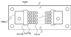
図2および図3を参照して、本発明の第1実施形態に係るコイル装置Lu1の構成について詳細に説明する。図2aは、本発明の第1実施形態に係るコイル装置の回路構成を模式的に示した図である。図2bは、本発明の第1実施形態に係るコイル装置における第1のキャパシタ回路の構成を模式的に示した図である。図3aは、本発明の第1実施形態に係るコイル装置を平面視した図である。図3bは、図3aにおける切断線A−Aに沿うコイル装置の断面図である。なお、説明の便宜上、図3aと図3bにおいて、キャパシタ回路は省略している。
次に、本発明の第2実施形態に係るコイル装置について説明する。第2実施形態に係るコイル装置が備える構成は、第1実施形態に係るコイル装置Lu1と同様である。第2実施形態に係るコイル装置においては、電力伝送用コイルL1の一方端に接続される第1のキャパシタ回路X10の合成静電容量と、電力伝送用コイルL1の他方端に接続される第2のキャパシタ回路X11の合成静電容量が略等しくなっている。ここで、理想的には第1のキャパシタ回路X10の合成静電容量と第2のキャパシタ回路X11の合成静電容量が一致していることが好ましいが、第1および第2のキャパシタ回路X10,X11を構成する複数のキャパシタ素子の公差や複数のキャパシタ素子の製造上の誤差等による差も「略等しい」の範囲に含まれることを意味する。
次に、図5を参照して、本発明の第3実施形態に係るコイル装置について詳細に説明する。図5は、本発明の第3実施形態に係るコイル装置における第1のキャパシタ回路の構成を模式的に示した図である。第3実施形態に係るコイル装置が備える構成は、第1実施形態に係るコイル装置Lu1と同様である。第3実施形態に係るコイル装置においては、第1および第2のキャパシタ回路X10,X11(キャパシタ回路X1)を構成する複数のキャパシタ素子CAP1の構成が異なる点で第1実施形態と相違する。なお、第1のキャパシタ回路X10と第2のキャパシタ回路X11の構成は同様のため、ここでは第1のキャパシタ回路X10の構成のみ説明する。
次に、図6を参照して、本発明の第3実施形態に係るコイル装置について詳細に説明する。図6は、本発明の第4実施形態に係るコイル装置における第1のキャパシタ回路の構成を模式的に示した図である。第4実施形態に係るコイル装置が備える構成は、第1実施形態に係るコイル装置Lu1と同様である。第4実施形態に係るコイル装置においては、第1および第2のキャパシタ回路X10,X11(キャパシタ回路X1)を構成する複数のキャパシタ素子CAP1の接続構成が異なる点で第1実施形態と相違する。なお、第1のキャパシタ回路X10と第2のキャパシタ回路X11の構成は同様のため、ここでは第1のキャパシタ回路X10の構成のみ説明する。
図7を参照して、本発明の第5実施形態に係るコイル装置Lu5の構成について詳細に説明する。図7は、本発明の第5実施形態に係るコイル装置の回路構成を模式的に示した図である。コイル装置Lu5は、図7に示されるように、電力伝送用コイルL1と、金属部SDと、キャパシタ回路X5と、計測部VSG1を有する。電力伝送用コイルL1、金属部SD、計測部VSG1の構成は、第1実施形態に係るコイル装置Lu1と同様である。第5実施形態に係るコイル装置Lu5は、キャパシタ回路X1に代えてキャパシタ回路X5を備えている点において、第1実施形態と相違する。以下、第1実施形態と異なる点を中心に説明する。

Claims (4)
- 電力伝送用コイルと、
前記電力伝送用コイルに接続され、複数のキャパシタ素子を有するキャパシタ回路と、
前記電力伝送用コイルと近接して配置される導電性の金属部と、
前記金属部に発生する電圧もしくは、電流を計測する計測部を備え、
前記キャパシタ回路は、前記電力伝送用コイルの一方端に接続される第1のキャパシタ回路と、前記電力伝送用コイルの他方端に接続される第2のキャパシタ回路を有し、
前記第1のキャパシタ回路の合成静電容量は、前記第2のキャパシタ回路の合成静電容量と略等しいことを特徴とするコイル装置。 - 前記複数のキャパシタ素子の各々は、積層セラミックコンデンサから構成され、
前記キャパシタ回路は、前記複数のキャパシタ素子が直並列接続されたキャパシタ群を有することを特徴とする請求項1に記載のコイル装置。 - 前記複数のキャパシタ素子の各々は、フィルムコンデンサから構成され、
前記キャパシタ回路は、前記複数のキャパシタ素子が直列接続されたキャパシタ部を複数有することを特徴とする請求項1に記載のコイル装置。 - 給電コイル装置を含むワイヤレス給電装置と、
受電コイル装置を含むワイヤレス受電装置を備え、
前記給電コイル装置と、前記受電コイル装置の少なくとも一方が、請求項1〜3のいずれか一項に記載のコイル装置であることを特徴とするワイヤレス電力伝送装置。
Priority Applications (3)
| Application Number | Priority Date | Filing Date | Title |
|---|---|---|---|
| CN201610798136.0A CN106487100B (zh) | 2015-09-02 | 2016-08-31 | 线圈装置及无线电力传输装置 |
| DE102016116342.2A DE102016116342A1 (de) | 2015-09-02 | 2016-09-01 | Spulenvorrichtung und drahtlos-leistungsübertragungsvorrichtung |
| US15/254,331 US10284017B2 (en) | 2015-09-02 | 2016-09-01 | Coil device and wireless power transmission device |
Applications Claiming Priority (2)
| Application Number | Priority Date | Filing Date | Title |
|---|---|---|---|
| JP2015172823 | 2015-09-02 | ||
| JP2015172823 | 2015-09-02 |
Publications (2)
| Publication Number | Publication Date |
|---|---|
| JP2017051084A JP2017051084A (ja) | 2017-03-09 |
| JP6747149B2 true JP6747149B2 (ja) | 2020-08-26 |
Family
ID=58280542
Family Applications (1)
| Application Number | Title | Priority Date | Filing Date |
|---|---|---|---|
| JP2016152550A Active JP6747149B2 (ja) | 2015-09-02 | 2016-08-03 | コイル装置及びワイヤレス電力伝送装置 |
Country Status (1)
| Country | Link |
|---|---|
| JP (1) | JP6747149B2 (ja) |
Families Citing this family (1)
| Publication number | Priority date | Publication date | Assignee | Title |
|---|---|---|---|---|
| JP2019087592A (ja) | 2017-11-06 | 2019-06-06 | Tdk株式会社 | コンデンサモジュール、共振器、ワイヤレス送電装置、ワイヤレス受電装置、ワイヤレス電力伝送システム |
Family Cites Families (6)
| Publication number | Priority date | Publication date | Assignee | Title |
|---|---|---|---|---|
| JP2009071960A (ja) * | 2007-09-12 | 2009-04-02 | Meleagros Corp | 電力伝送装置、電力伝送装置の送電装置、電力伝送装置の受電装置、高周波電力回路用キャパシタの性能評価方法および性能評価装置 |
| JP6120088B2 (ja) * | 2011-11-04 | 2017-04-26 | パナソニックIpマネジメント株式会社 | コイルユニット |
| JP5293851B2 (ja) * | 2012-02-20 | 2013-09-18 | 住友電気工業株式会社 | コイルユニット及び非接触給電システム |
| JP6102242B2 (ja) * | 2012-12-20 | 2017-03-29 | Tdk株式会社 | ワイヤレス給電装置及びワイヤレス電力伝送装置 |
| JP2014217199A (ja) * | 2013-04-26 | 2014-11-17 | 株式会社ノーリツ | 電力変換装置 |
| US9562955B2 (en) * | 2014-01-20 | 2017-02-07 | Qualcomm Incorporated | Methods and apparatus for magnetic field strength measurement |
-
2016
- 2016-08-03 JP JP2016152550A patent/JP6747149B2/ja active Active
Also Published As
| Publication number | Publication date |
|---|---|
| JP2017051084A (ja) | 2017-03-09 |
Similar Documents
| Publication | Publication Date | Title |
|---|---|---|
| EP3282539B1 (en) | Power transmission device, vehicle equipped with power transmission device, and wireless power transmission system | |
| EP3016231B1 (en) | Power transmission device, vehicle equipped with power transmission device, and wireless power transmission system | |
| JP6551853B2 (ja) | 送電装置、送電装置を搭載した車両及び無線電力伝送システム | |
| CN101681717B (zh) | 用于高压应用的高频变压器 | |
| US10284017B2 (en) | Coil device and wireless power transmission device | |
| JP2017514452A (ja) | モバイル装置用途向け無線エネルギ伝送 | |
| CN106908634A (zh) | 一种带有c型磁环的基于磁电层合材料的交流电流传感器 | |
| JP6667163B2 (ja) | 送電装置、送電装置を搭載した車両及び無線電力伝送システム | |
| JP2016039644A (ja) | 送電装置および無線電力伝送システム | |
| WO2016125725A1 (ja) | 電流検出素子及び電力伝送システム | |
| JP2014224695A (ja) | 電流計測装置 | |
| JP6003429B2 (ja) | 測定装置 | |
| CN206675527U (zh) | 射频体线圈及磁共振成像系统 | |
| JP6747149B2 (ja) | コイル装置及びワイヤレス電力伝送装置 | |
| JP5240529B2 (ja) | スイッチング電源装置 | |
| Zahedi et al. | Comparative study of self-compensated coil geometries for wireless power transfer system | |
| KR101629964B1 (ko) | 제어기능성 및 통합트랜스포머를 갖는 전력반도체 모듈 | |
| JP6361825B2 (ja) | 電流検出素子、送電装置及び電力伝送システム | |
| US9991749B2 (en) | Coil unit, wireless power feeding device, wireless power receiving device, and wireless power transmission device | |
| JP2007157985A (ja) | 非接触タイプの電源供給システム | |
| JP5911441B2 (ja) | Dc−dcコンバータのトランス配線構造 | |
| US9935500B2 (en) | Coil unit, wireless power feeding device, wireless power receiving device, and wireless power transmission device | |
| WO2021131607A1 (ja) | 異物検出装置、送電装置、受電装置および電力伝送システム | |
| JP2016119755A (ja) | 検出コイル、給電コイル、及び、受電コイル | |
| WO2013145080A1 (ja) | 短絡検査装置及び短絡検査方法 |
Legal Events
| Date | Code | Title | Description |
|---|---|---|---|
| A621 | Written request for application examination |
Free format text: JAPANESE INTERMEDIATE CODE: A621 Effective date: 20190327 |
|
| A977 | Report on retrieval |
Free format text: JAPANESE INTERMEDIATE CODE: A971007 Effective date: 20200220 |
|
| A131 | Notification of reasons for refusal |
Free format text: JAPANESE INTERMEDIATE CODE: A131 Effective date: 20200310 |
|
| A521 | Request for written amendment filed |
Free format text: JAPANESE INTERMEDIATE CODE: A523 Effective date: 20200507 |
|
| TRDD | Decision of grant or rejection written | ||
| A01 | Written decision to grant a patent or to grant a registration (utility model) |
Free format text: JAPANESE INTERMEDIATE CODE: A01 Effective date: 20200707 |
|
| A61 | First payment of annual fees (during grant procedure) |
Free format text: JAPANESE INTERMEDIATE CODE: A61 Effective date: 20200720 |
|
| R150 | Certificate of patent or registration of utility model |
Ref document number: 6747149 Country of ref document: JP Free format text: JAPANESE INTERMEDIATE CODE: R150 |
|
| R250 | Receipt of annual fees |
Free format text: JAPANESE INTERMEDIATE CODE: R250 |