JP6748006B2 - 圧力センサ - Google Patents
圧力センサ Download PDFInfo
- Publication number
- JP6748006B2 JP6748006B2 JP2017044554A JP2017044554A JP6748006B2 JP 6748006 B2 JP6748006 B2 JP 6748006B2 JP 2017044554 A JP2017044554 A JP 2017044554A JP 2017044554 A JP2017044554 A JP 2017044554A JP 6748006 B2 JP6748006 B2 JP 6748006B2
- Authority
- JP
- Japan
- Prior art keywords
- pressure
- temperature
- diaphragm
- detection device
- inner container
- Prior art date
- Legal status (The legal status is an assumption and is not a legal conclusion. Google has not performed a legal analysis and makes no representation as to the accuracy of the status listed.)
- Active
Links
Images


Classifications
-
- G—PHYSICS
- G01—MEASURING; TESTING
- G01L—MEASURING FORCE, STRESS, TORQUE, WORK, MECHANICAL POWER, MECHANICAL EFFICIENCY, OR FLUID PRESSURE
- G01L9/00—Measuring steady of quasi-steady pressure of fluid or fluent solid material by electric or magnetic pressure-sensitive elements; Transmitting or indicating the displacement of mechanical pressure-sensitive elements, used to measure the steady or quasi-steady pressure of a fluid or fluent solid material, by electric or magnetic means
- G01L9/12—Measuring steady of quasi-steady pressure of fluid or fluent solid material by electric or magnetic pressure-sensitive elements; Transmitting or indicating the displacement of mechanical pressure-sensitive elements, used to measure the steady or quasi-steady pressure of a fluid or fluent solid material, by electric or magnetic means by making use of variations in capacitance, i.e. electric circuits therefor
- G01L9/125—Measuring steady of quasi-steady pressure of fluid or fluent solid material by electric or magnetic pressure-sensitive elements; Transmitting or indicating the displacement of mechanical pressure-sensitive elements, used to measure the steady or quasi-steady pressure of a fluid or fluent solid material, by electric or magnetic means by making use of variations in capacitance, i.e. electric circuits therefor with temperature compensating means
-
- G—PHYSICS
- G01—MEASURING; TESTING
- G01L—MEASURING FORCE, STRESS, TORQUE, WORK, MECHANICAL POWER, MECHANICAL EFFICIENCY, OR FLUID PRESSURE
- G01L9/00—Measuring steady of quasi-steady pressure of fluid or fluent solid material by electric or magnetic pressure-sensitive elements; Transmitting or indicating the displacement of mechanical pressure-sensitive elements, used to measure the steady or quasi-steady pressure of a fluid or fluent solid material, by electric or magnetic means
- G01L9/02—Measuring steady of quasi-steady pressure of fluid or fluent solid material by electric or magnetic pressure-sensitive elements; Transmitting or indicating the displacement of mechanical pressure-sensitive elements, used to measure the steady or quasi-steady pressure of a fluid or fluent solid material, by electric or magnetic means by making use of variations in ohmic resistance, e.g. of potentiometers, electric circuits therefor, e.g. bridges, amplifiers or signal conditioning
- G01L9/04—Measuring steady of quasi-steady pressure of fluid or fluent solid material by electric or magnetic pressure-sensitive elements; Transmitting or indicating the displacement of mechanical pressure-sensitive elements, used to measure the steady or quasi-steady pressure of a fluid or fluent solid material, by electric or magnetic means by making use of variations in ohmic resistance, e.g. of potentiometers, electric circuits therefor, e.g. bridges, amplifiers or signal conditioning of resistance-strain gauges
- G01L9/045—Measuring steady of quasi-steady pressure of fluid or fluent solid material by electric or magnetic pressure-sensitive elements; Transmitting or indicating the displacement of mechanical pressure-sensitive elements, used to measure the steady or quasi-steady pressure of a fluid or fluent solid material, by electric or magnetic means by making use of variations in ohmic resistance, e.g. of potentiometers, electric circuits therefor, e.g. bridges, amplifiers or signal conditioning of resistance-strain gauges with electric temperature compensating means
-
- G—PHYSICS
- G01—MEASURING; TESTING
- G01L—MEASURING FORCE, STRESS, TORQUE, WORK, MECHANICAL POWER, MECHANICAL EFFICIENCY, OR FLUID PRESSURE
- G01L1/00—Measuring force or stress, in general
- G01L1/20—Measuring force or stress, in general by measuring variations in ohmic resistance of solid materials or of electrically-conductive fluids; by making use of electrokinetic cells, i.e. liquid-containing cells wherein an electrical potential is produced or varied upon the application of stress
- G01L1/22—Measuring force or stress, in general by measuring variations in ohmic resistance of solid materials or of electrically-conductive fluids; by making use of electrokinetic cells, i.e. liquid-containing cells wherein an electrical potential is produced or varied upon the application of stress using resistance strain gauges
- G01L1/2268—Arrangements for correcting or for compensating unwanted effects
- G01L1/2281—Arrangements for correcting or for compensating unwanted effects for temperature variations
-
- G—PHYSICS
- G01—MEASURING; TESTING
- G01L—MEASURING FORCE, STRESS, TORQUE, WORK, MECHANICAL POWER, MECHANICAL EFFICIENCY, OR FLUID PRESSURE
- G01L9/00—Measuring steady of quasi-steady pressure of fluid or fluent solid material by electric or magnetic pressure-sensitive elements; Transmitting or indicating the displacement of mechanical pressure-sensitive elements, used to measure the steady or quasi-steady pressure of a fluid or fluent solid material, by electric or magnetic means
- G01L9/0001—Transmitting or indicating the displacement of elastically deformable gauges by electric, electro-mechanical, magnetic or electro-magnetic means
- G01L9/0008—Transmitting or indicating the displacement of elastically deformable gauges by electric, electro-mechanical, magnetic or electro-magnetic means using vibrations
- G01L9/0016—Transmitting or indicating the displacement of elastically deformable gauges by electric, electro-mechanical, magnetic or electro-magnetic means using vibrations of a diaphragm
-
- G—PHYSICS
- G01—MEASURING; TESTING
- G01L—MEASURING FORCE, STRESS, TORQUE, WORK, MECHANICAL POWER, MECHANICAL EFFICIENCY, OR FLUID PRESSURE
- G01L9/00—Measuring steady of quasi-steady pressure of fluid or fluent solid material by electric or magnetic pressure-sensitive elements; Transmitting or indicating the displacement of mechanical pressure-sensitive elements, used to measure the steady or quasi-steady pressure of a fluid or fluent solid material, by electric or magnetic means
- G01L9/0041—Transmitting or indicating the displacement of flexible diaphragms
- G01L9/0072—Transmitting or indicating the displacement of flexible diaphragms using variations in capacitance
Landscapes
- Physics & Mathematics (AREA)
- General Physics & Mathematics (AREA)
- Measuring Fluid Pressure (AREA)
Description
Claims (3)
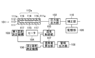
- 測定対象からの圧力を受けて変位するダイアフラムを備え、前記ダイアフラムの変位を他の物理量の変化に変換する検出デバイスと、
前記ダイアフラムの変位による前記他の物理量の変化を圧力値に変換して出力するように構成された圧力値出力部と、
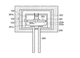
前記検出デバイスを収容する内側容器と、
前記内側容器を収容する外側容器と、
前記内側容器に接続され前記内側容器の内部に測定対象の圧力を導入するための圧力導入管と、
前記内側容器の内部に設けられ、前記内側容器の内部空間を前記圧力導入管を介して前記測定対象の圧力が導入される圧力検出側の空間と、前記圧力検出側の空間と反対側の空間で前記検出デバイスが配置される素子配置側の空間とに分離するとともに、前記素子配置側の面に前記検出デバイスが接合され、前記圧力検出側の圧力を前記検出デバイスの前記ダイアフラムに導く圧力導入孔を有する隔壁と
前記内側容器の前記素子配置側の外側壁面に設けられた第1温度測定機構と、
前記外側容器の外側に壁面に設置されて前記外側容器の内部を加熱するための加熱機構と、
前記加熱機構の動作を制御して、前記第1温度測定機構で測定される第1温度値を設定温度に近づけるように構成された温度制御部と、
前記加熱機構の温度を測定する第2温度測定機構と、
前記第1温度測定機構が測定した第1温度値と第2温度測定機構が測定した第2温度値との温度差を求めるように構成された温度差算出部と、
前記温度差算出部が算出した温度差が設定範囲を外れた場合に警報を発令するように構成された警報出力部と
を備えることを特徴とする圧力センサ。 - 請求項1記載の圧力センサにおいて、
前記検出デバイスは、前記ダイアフラムと離間して前記ダイアフラムを支持する基台と、前記ダイアフラムに設けられた第1の電極と、前記基台に設けられ前記第1の電極と向いあう第2の電極とを有し、
前記圧力値出力部は、前記ダイアフラムの変位による前記第1の電極と前記第2の電極との間の容量変化を前記圧力値に変換して出力することを特徴とする圧力センサ。 - 請求項1または2記載の圧力センサにおいて、
前記検出デバイスは、測定対象からの圧力を受ける受圧部となる前記ダイアフラムと反対側に真空とされた容量室を備えることを特徴とする圧力センサ。
Priority Applications (4)
| Application Number | Priority Date | Filing Date | Title |
|---|---|---|---|
| JP2017044554A JP6748006B2 (ja) | 2017-03-09 | 2017-03-09 | 圧力センサ |
| KR1020180025626A KR102017300B1 (ko) | 2017-03-09 | 2018-03-05 | 압력 센서 |
| CN201810191413.0A CN108572046B (zh) | 2017-03-09 | 2018-03-08 | 压力传感器 |
| US15/915,367 US10585010B2 (en) | 2017-03-09 | 2018-03-08 | Pressure sensor having a temperature control unit and a temperature difference calculation unit |
Applications Claiming Priority (1)
| Application Number | Priority Date | Filing Date | Title |
|---|---|---|---|
| JP2017044554A JP6748006B2 (ja) | 2017-03-09 | 2017-03-09 | 圧力センサ |
Publications (2)
| Publication Number | Publication Date |
|---|---|
| JP2018146530A JP2018146530A (ja) | 2018-09-20 |
| JP6748006B2 true JP6748006B2 (ja) | 2020-08-26 |
Family
ID=63446352
Family Applications (1)
| Application Number | Title | Priority Date | Filing Date |
|---|---|---|---|
| JP2017044554A Active JP6748006B2 (ja) | 2017-03-09 | 2017-03-09 | 圧力センサ |
Country Status (4)
| Country | Link |
|---|---|
| US (1) | US10585010B2 (ja) |
| JP (1) | JP6748006B2 (ja) |
| KR (1) | KR102017300B1 (ja) |
| CN (1) | CN108572046B (ja) |
Families Citing this family (11)
| Publication number | Priority date | Publication date | Assignee | Title |
|---|---|---|---|---|
| JP6564358B2 (ja) * | 2016-12-08 | 2019-08-21 | 長野計器株式会社 | 物理量測定装置 |
| JP6815221B2 (ja) * | 2017-02-17 | 2021-01-20 | アズビル株式会社 | 静電容量型圧力センサ |
| IT201700073763A1 (it) * | 2017-07-05 | 2019-01-05 | St Microelectronics Srl | Sensore capacitivo di pressione per il monitoraggio di strutture edilizie, in particolare di calcestruzzo |
| JP7092603B2 (ja) * | 2018-08-03 | 2022-06-28 | 株式会社ユニバーサルエンターテインメント | 遊技機 |
| FR3092167B1 (fr) * | 2019-01-29 | 2021-10-22 | Arianegroup Sas | Capteur pour la mesure d’une première grandeur physique dont la mesure est influencée par une deuxième grandeur physique |
| JP7372062B2 (ja) * | 2019-07-02 | 2023-10-31 | アズビル株式会社 | 圧力センサ |
| JP7553261B2 (ja) * | 2020-04-01 | 2024-09-18 | アズビル株式会社 | 圧力センサ用筐体およびこれを備える圧力センサ |
| JP7690277B2 (ja) * | 2020-11-27 | 2025-06-10 | アズビル株式会社 | 隔膜真空計 |
| JP7534198B2 (ja) * | 2020-11-27 | 2024-08-14 | アズビル株式会社 | 隔膜真空計 |
| JP7704564B2 (ja) * | 2021-05-10 | 2025-07-08 | アズビル株式会社 | 隔膜真空計 |
| CN116007841A (zh) * | 2022-12-30 | 2023-04-25 | 苏州科米隆机电有限公司 | 压力传感器芯片的标定设备和标定方法 |
Family Cites Families (21)
| Publication number | Priority date | Publication date | Assignee | Title |
|---|---|---|---|---|
| US5625152A (en) * | 1996-01-16 | 1997-04-29 | Mks Instruments, Inc. | Heated pressure transducer assembly |
| JP3404257B2 (ja) | 1997-07-11 | 2003-05-06 | 三菱電機株式会社 | 圧力センサ装置 |
| US6588280B1 (en) * | 2002-04-22 | 2003-07-08 | Mks Instruments, Inc. | Pressure transducer with compensation for thermal transients |
| US6701790B2 (en) * | 2002-06-13 | 2004-03-09 | Mykrolis Corporation | Temperature regulator for use with a pressure sensing device |
| JP4014006B2 (ja) | 2004-06-17 | 2007-11-28 | 株式会社山武 | 圧力センサ |
| US7946178B2 (en) * | 2007-06-19 | 2011-05-24 | Inficon Gmbh | Vacuum measuring cell device having a heater |
| JP2009133838A (ja) * | 2007-11-06 | 2009-06-18 | Canon Anelva Technix Corp | 静電容量型隔膜式圧力センサ |
| JP5114251B2 (ja) * | 2008-03-05 | 2013-01-09 | 株式会社アルバック | 真空処理装置 |
| JP2009244149A (ja) * | 2008-03-31 | 2009-10-22 | Yamatake Corp | 圧力センサ |
| JP5445020B2 (ja) * | 2009-10-20 | 2014-03-19 | 横河電機株式会社 | 電子式差圧・圧力伝送器 |
| JP5576331B2 (ja) | 2011-03-31 | 2014-08-20 | アズビル株式会社 | 圧力センサ装置 |
| EP2717030A4 (en) * | 2011-05-31 | 2015-09-23 | Japan Science & Tech Agency | METHOD FOR TEMPERATURE COMPENSATION IN A SENSOR, CALCULATION PROGRAM FOR THE TEMPERATURE COMPENSATION PROCESS, CALCULATION PROCESSING DEVICE AND SENSOR |
| JP4963138B1 (ja) * | 2011-07-27 | 2012-06-27 | 株式会社トライフォース・マネジメント | 力覚センサ |
| JP6058986B2 (ja) * | 2012-11-29 | 2017-01-11 | アズビル株式会社 | 差圧センサ |
| JP6002016B2 (ja) | 2012-11-30 | 2016-10-05 | アズビル株式会社 | 静電容量型圧力センサ |
| DE102013101936A1 (de) * | 2013-02-27 | 2014-08-28 | Endress + Hauser Gmbh + Co. Kg | Drucksensor |
| US10130123B2 (en) * | 2013-03-15 | 2018-11-20 | Juul Labs, Inc. | Vaporizer devices with blow discrimination |
| JP6130765B2 (ja) * | 2013-09-30 | 2017-05-17 | アズビル株式会社 | 静電容量型圧力センサ |
| DE102014200507A1 (de) * | 2014-01-14 | 2015-07-16 | Robert Bosch Gmbh | Mikromechanische Drucksensorvorrichtung und entsprechendes Herstellungsverfahren |
| JP6154760B2 (ja) * | 2014-02-10 | 2017-06-28 | アズビル株式会社 | 静電容量型圧力センサ |
| JP2016180651A (ja) * | 2015-03-24 | 2016-10-13 | アズビル株式会社 | 堆積物状態推定装置、堆積物状態推定方法および堆積物状態推定システム |
-
2017
- 2017-03-09 JP JP2017044554A patent/JP6748006B2/ja active Active
-
2018
- 2018-03-05 KR KR1020180025626A patent/KR102017300B1/ko active Active
- 2018-03-08 CN CN201810191413.0A patent/CN108572046B/zh active Active
- 2018-03-08 US US15/915,367 patent/US10585010B2/en active Active
Also Published As
| Publication number | Publication date |
|---|---|
| CN108572046A (zh) | 2018-09-25 |
| US10585010B2 (en) | 2020-03-10 |
| KR102017300B1 (ko) | 2019-09-03 |
| US20180259409A1 (en) | 2018-09-13 |
| JP2018146530A (ja) | 2018-09-20 |
| CN108572046B (zh) | 2020-04-24 |
| KR20180103706A (ko) | 2018-09-19 |
Similar Documents
| Publication | Publication Date | Title |
|---|---|---|
| JP6748006B2 (ja) | 圧力センサ | |
| JP5524055B2 (ja) | 測定セル構造を較正する方法、および作動させる方法 | |
| JP6815283B2 (ja) | 静電容量型圧力センサ | |
| JP6748000B2 (ja) | 圧力センサ | |
| KR20170101789A (ko) | 압력 센서 상태 검출 방법 및 시스템 | |
| JP2015148579A (ja) | 静電容量型圧力センサ | |
| CN108431571B (zh) | 压力传感器 | |
| US20160084723A1 (en) | Pressure Sensor | |
| JP2020085627A (ja) | 圧力センサ | |
| JP2016015457A (ja) | 基板処理装置及び基板処理方法 | |
| JP7690277B2 (ja) | 隔膜真空計 | |
| KR20040102631A (ko) | 진공 측정기 | |
| Plöchinger | Thermal conductivity measurement with “free floating” molecule detector | |
| JP2022174404A (ja) | 隔膜真空計 | |
| JP2019046286A (ja) | 異常検知方法および異常検知装置 |
Legal Events
| Date | Code | Title | Description |
|---|---|---|---|
| A621 | Written request for application examination |
Free format text: JAPANESE INTERMEDIATE CODE: A621 Effective date: 20190917 |
|
| A131 | Notification of reasons for refusal |
Free format text: JAPANESE INTERMEDIATE CODE: A131 Effective date: 20200512 |
|
| A521 | Request for written amendment filed |
Free format text: JAPANESE INTERMEDIATE CODE: A523 Effective date: 20200617 |
|
| TRDD | Decision of grant or rejection written | ||
| A01 | Written decision to grant a patent or to grant a registration (utility model) |
Free format text: JAPANESE INTERMEDIATE CODE: A01 Effective date: 20200707 |
|
| A61 | First payment of annual fees (during grant procedure) |
Free format text: JAPANESE INTERMEDIATE CODE: A61 Effective date: 20200806 |
|
| R150 | Certificate of patent or registration of utility model |
Ref document number: 6748006 Country of ref document: JP Free format text: JAPANESE INTERMEDIATE CODE: R150 |
|
| R250 | Receipt of annual fees |
Free format text: JAPANESE INTERMEDIATE CODE: R250 |
|
| R250 | Receipt of annual fees |
Free format text: JAPANESE INTERMEDIATE CODE: R250 |