JP6762015B2 - Connector - Google Patents

Connector Download PDF

Info

Publication number
JP6762015B2
JP6762015B2 JP2017001190A JP2017001190A JP6762015B2 JP 6762015 B2 JP6762015 B2 JP 6762015B2 JP 2017001190 A JP2017001190 A JP 2017001190A JP 2017001190 A JP2017001190 A JP 2017001190A JP 6762015 B2 JP6762015 B2 JP 6762015B2
Authority
JP
Japan
Prior art keywords
locking
male
connecting member
engaging
female
Prior art date
Legal status (The legal status is an assumption and is not a legal conclusion. Google has not performed a legal analysis and makes no representation as to the accuracy of the status listed.)
Active
Application number
JP2017001190A
Other languages
Japanese (ja)
Other versions
JP2018111921A (en
Inventor
勝 石黒
勝 石黒
椙山 晃
晃 椙山
Current Assignee (The listed assignees may be inaccurate. Google has not performed a legal analysis and makes no representation or warranty as to the accuracy of the list.)
Mitsuchi Corp
Original Assignee
Mitsuchi Corp
Priority date (The priority date is an assumption and is not a legal conclusion. Google has not performed a legal analysis and makes no representation as to the accuracy of the date listed.)
Filing date
Publication date
Application filed by Mitsuchi Corp filed Critical Mitsuchi Corp
Priority to JP2017001190A priority Critical patent/JP6762015B2/en
Publication of JP2018111921A publication Critical patent/JP2018111921A/en
Application granted granted Critical
Publication of JP6762015B2 publication Critical patent/JP6762015B2/en
Active legal-status Critical Current
Anticipated expiration legal-status Critical

Links

Images

Landscapes

  • Lining And Supports For Tunnels (AREA)

Description

本発明は、連結具に関する。 The present invention relates to a connector.

従来、部材相互の連結具として、円筒状のピンと、このピンが挿入される収納室を有し、この収納室内には、内周面に複数の爪を設けるとともに、爪の内径をピンの外径より小さく形成した複数の嵌合部材と、嵌合部材間に配設したスペーサが設けられ、ピンを収納室内に挿入すると、嵌合部材の爪がピンの外周面に圧接して、ピンを設けた部材と、収納室を設けた部材を相互に連結するようにしたものが知られている(特許文献1参照)。 Conventionally, as a connecting tool between members, a cylindrical pin and a storage chamber into which the pin is inserted are provided. In this storage chamber, a plurality of claws are provided on the inner peripheral surface, and the inner diameter of the claw is set outside the pin. A plurality of fitting members formed smaller than the diameter and spacers arranged between the fitting members are provided, and when the pin is inserted into the storage chamber, the claws of the fitting member are pressed against the outer peripheral surface of the pin to press the pin. A member provided with a storage chamber and a member provided with a storage chamber are known to be connected to each other (see Patent Document 1).

特開2012−180697号公報Japanese Unexamined Patent Publication No. 2012-180697

前記の爪は、ピン等が挿入された際に奥側で、かつ、ピン側へ傾斜した状態で相互に連結される。この連結状態において、ピン等が抜ける方向に力が作用し、所定以上の負荷が嵌合部材等に作用すると、爪が挿入側に反り返ってしまいピン等が抜けてしまう恐れがある。 The claws are connected to each other on the back side when the pin or the like is inserted and in a state of being inclined toward the pin side. In this connected state, if a force acts in the direction in which the pin or the like comes off and a load of a predetermined value or more acts on the fitting member or the like, the claw may bend back to the insertion side and the pin or the like may come off.

そこで本発明は、爪が挿入側に反ることを抑制することで、より締結力を高めた連結具を提供することを目的とするものである。 Therefore, an object of the present invention is to provide a connecting tool having a higher fastening force by suppressing the claw from warping toward the insertion side.

前記課題を解決するために、請求項1記載の発明は、雌型連結部材と、先部に雄型係止部材を有する雄型連結部材とからなり、
前記雌型連結部材の内部に、前記雄型係止部材を挿入することができる収納室を形成し、
前記収納室内に、前記雄型連結部材と前記雌型連結部材との連結時に、前記雄型係止部材の外周面に圧接する係合部材と、抑制部材を設け、
該係合部材は、前記雄型係止部材の挿入側とは反対の奥側に至るほど、雌型連結部材の軸芯側へ傾斜する傾斜部を有し、
前記抑制部材は、前記軸芯側部で、かつ、奥側において、前記軸芯に向かうほど、前記雄型係止部材の挿入側とは反対の奥側に傾斜するテーパ面を形成し、
該テーパ面により、前記傾斜部における前記雄型係止部材の挿入側への曲折を抑制することを特徴とするものである。
In order to solve the above problems, the invention according to claim 1 comprises a female connecting member and a male connecting member having a male locking member at the tip.
A storage chamber into which the male locking member can be inserted is formed inside the female connecting member.
An engaging member and a restraining member that press-contact the outer peripheral surface of the male locking member when the male connecting member and the female connecting member are connected are provided in the storage chamber.
The engaging member has an inclined portion that inclines toward the axis side of the female connecting member toward the inner side opposite to the insertion side of the male locking member.
The restraining member forms a tapered surface on the side of the shaft core and on the back side, which is inclined toward the back side opposite to the insertion side of the male locking member toward the shaft core.
The tapered surface suppresses bending of the male locking member to the insertion side at the inclined portion.

請求項2記載の発明は、雌型連結部材と、外周面に係合部を有する雄型係止部材を先部に設けた雄型連結部材とからなり、
前記雌型連結部材の内部に、前記雄型係止部材を挿入することができる収納室を形成し、
前記収納室内に、前記雄型連結部材と前記雌型連結部材との連結時に、前記雄型係止部材の係合部に係合する係合部材と、抑制部材を設け、
該係合部材は、前記雄型係止部材の挿入側とは反対の奥側に至るほど、雌型連結部材の軸芯側へ傾斜する傾斜部を有し、
前記抑制部材は、前記軸芯側部で、かつ、奥側において、前記軸芯に向かうほど、前記雄型係止部材の挿入側とは反対の奥側に傾斜するテーパ面を形成し、
該テーパ面により、前記傾斜部における前記雄型係止部材の挿入側への曲折を抑制することを特徴とするものである。
The invention according to claim 2 comprises a female connecting member and a male connecting member having a male locking member having an engaging portion on an outer peripheral surface at the tip thereof.
A storage chamber into which the male locking member can be inserted is formed inside the female connecting member.
An engaging member and a restraining member that engage with the engaging portion of the male locking member when the male connecting member and the female connecting member are connected are provided in the storage chamber.
The engaging member has an inclined portion that inclines toward the axis side of the female connecting member toward the inner side opposite to the insertion side of the male locking member.
The restraining member forms a tapered surface on the side of the shaft core and on the back side, which is inclined toward the back side opposite to the insertion side of the male locking member toward the shaft core.
The tapered surface suppresses bending of the male locking member to the insertion side at the inclined portion.

請求項3記載の発明は、請求項2記載の発明において、前記雄型係止部材の係合部は、係止山及び係止谷を交互に形成してなる係止部を外面に刻設して形成された係止部で構成されていることを特徴とするものである。 The invention according to claim 3 is the invention according to claim 2, wherein the engaging portion of the male locking member has a locking portion formed on an outer surface in which locking peaks and locking valleys are alternately formed. It is characterized in that it is composed of the locking portion formed in the above.

請求項4記載の発明は、請求項2記載の発明において、前記雄型係止部材の係合部は、雄型係止部材の外周面に形成した係合溝で構成されていることを特徴とするものである。 The invention according to claim 4 is characterized in that, in the invention according to claim 2, the engaging portion of the male locking member is formed of an engaging groove formed on the outer peripheral surface of the male locking member. It is to be.

請求項5記載の発明は、請求項3記載の発明において、前記収納室内に、係止山及び係止谷を交互に形成してなる係止部を内面側に刻設した雌型係止部材を設け、前記雌型係止部材間に前記雄型係止部材を挿入することにより、前記係止部により構成される係止穴が拡径した後に、付勢手段により前記係止穴が縮径し前記雌型係止部材の係止部と、前記雄型係止部材の係止部とが噛合するようにしたことを特徴とするものである。 The invention according to claim 5 is a female locking member in which, in the invention according to claim 3, locking portions formed by alternately forming locking peaks and locking valleys are engraved on the inner surface side in the storage chamber. By inserting the male locking member between the female locking members, the locking hole formed by the locking portion is expanded in diameter, and then the locking hole is contracted by the urging means. It is characterized in that the locking portion of the female locking member and the locking portion of the male locking member are engaged with each other.

請求項6記載の発明は、請求項1乃至5の何れか1項に記載の発明において、前記係合部材は、プッシュナット又はスピードナットであることを特徴とするものである。 The invention according to claim 6 is the invention according to any one of claims 1 to 5, wherein the engaging member is a push nut or a speed nut.

請求項7記載の発明は、請求項1乃至6の何れか1項に記載の発明において、前記雄型連結部材と前記雌型連結部材を、コンクリート部材に固設したことを特徴とするものである。 The invention according to claim 7 is the invention according to any one of claims 1 to 6, wherein the male connecting member and the female connecting member are fixed to a concrete member. is there.

請求項8記載の発明は、請求項7記載の発明において、前記コンクリート部材は、シールドセグメントであることを特徴とするものである。 The invention according to claim 8 is the invention according to claim 7, wherein the concrete member is a shield segment.

本発明は、収納室内に、雄型係止部材と雌型係止部材との連結時に、雄型係止部材の外周面に圧接する係合部材と、抑制部材を設け、係合部材は、雄型係止部材の挿入側とは反対の奥側に傾斜する傾斜部を有し、抑制部材は、軸芯側部で、かつ、奥側において、前記軸芯に向かうほど、前記雄型係止部材の挿入側とは反対の奥側に傾斜するテーパ面を形成し、テーパ面により、前記傾斜部における前記雄型係止部材の挿入側への曲折を抑制するようにしたことにより、雌型連結部材と雄型連結部材の連結状態において、相互に離間する方向に力が作用した際に、抑制部材のテーパ面により、係合部材の傾斜部が、挿入側方向の逆側に折れ曲がることが抑制され、上記従来技術と比較して、雌型連結部材と雄型連結部材の締結力を向上することができる。 In the present invention, an engaging member and a restraining member that press-contact the outer peripheral surface of the male locking member when the male locking member and the female locking member are connected are provided in the storage chamber. It has an inclined portion that is inclined to the back side opposite to the insertion side of the male locking member, and the restraining member is on the side of the shaft core and on the back side, the more toward the shaft core, the more the male mold is engaged. A tapered surface is formed on the back side opposite to the insertion side of the stop member, and the tapered surface suppresses bending of the male locking member to the insertion side in the inclined portion, so that the female In the connected state of the mold connecting member and the male connecting member, when a force is applied in a direction in which they are separated from each other, the inclined portion of the engaging member is bent to the opposite side in the insertion side direction due to the tapered surface of the suppressing member. Is suppressed, and the fastening force between the female connecting member and the male connecting member can be improved as compared with the above-mentioned conventional technique.

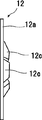
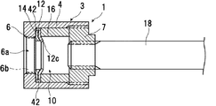
本発明の実施例1における雌型連結部材の部分断面図。FIG. 3 is a partial cross-sectional view of the female connecting member according to the first embodiment of the present invention. 本発明の実施例1における雄型連結部材の半面を断面とした部分断面図。FIG. 3 is a partial cross-sectional view taken along a half surface of the male connecting member according to the first embodiment of the present invention. 本発明の実施例1における雌型連結部材と雄型連結部材の連結状態を示す部分断面図。FIG. 3 is a partial cross-sectional view showing a connected state of the female connecting member and the male connecting member according to the first embodiment of the present invention. 本発明の実施例1における雌型連結部材の変形例を示す部分断面図。FIG. 3 is a partial cross-sectional view showing a modified example of the female connecting member according to the first embodiment of the present invention. 本発明の実施例1に用いる係合部材の正面図。The front view of the engaging member used in Example 1 of this invention. 図5の側面図。The side view of FIG. 本発明の実施例1における雌型連結部材の他の変形例を示す部分断面図。FIG. 3 is a partial cross-sectional view showing another modification of the female connecting member according to the first embodiment of the present invention. 本発明の実施例2における雌型連結部材の部分断面図。FIG. 2 is a partial cross-sectional view of a female connecting member according to a second embodiment of the present invention. 本発明の実施例3における雌型連結部材と雄型連結部材の連結状態を示す部分断面図。FIG. 3 is a partial cross-sectional view showing a connected state of the female connecting member and the male connecting member according to the third embodiment of the present invention. 本発明の実施例5における雌型連結部材と雄型連結部材の連結状態を示す部分断面図。FIG. 5 is a partial cross-sectional view showing a connected state of the female connecting member and the male connecting member according to the fifth embodiment of the present invention. 本発明の実施例5における他例の雌型連結部材と雄型連結部材の連結状態を示す部分断面図。FIG. 5 is a partial cross-sectional view showing a connected state of a female connecting member and a male connecting member of another example in Example 5 of the present invention. 本発明の実施例6における雌型連結部材と雄型連結部材の連結状態を示す部分断面図。FIG. 3 is a partial cross-sectional view showing a connected state of the female connecting member and the male connecting member in the sixth embodiment of the present invention.

本発明を実施するための形態を図に示す実施例に基づいて説明する。 A mode for carrying out the present invention will be described with reference to the examples shown in the figure.

[実施例1]
図1乃至図7は、本発明の実施例1を示す。
[Example 1]
1 to 7 show Example 1 of the present invention.

図1は、本実施例1の雌型連結部材1の部分断面図を示し、図2は、雌型連結部材1と連結する雄型連結部材2の部分断面図を示すものである。 FIG. 1 shows a partial cross-sectional view of the female connecting member 1 of the first embodiment, and FIG. 2 shows a partial cross-sectional view of the male connecting member 2 connected to the female connecting member 1.

雌型連結部材1は、ケーシング3を有し、該ケーシング3は、筒状、例えば円筒状に形成された筒部4、筒部4における雄型連結部材2の雄型係止部材5の挿入側端部に設けられた挿入部6、筒部4における挿入側とは反対側端部に設けられた蓋体7で構成されている。ケーシング3の内部には、雄型係止部材5の少なくとも一部を挿入することができる円筒状の収納室10が形成されている。なお、収納室10の断面形状は、円状以外にも、楕円形状、四角形等の多角形状など任意の形状に形成することができる。 The female connecting member 1 has a casing 3, and the casing 3 has a tubular portion 4, for example, a cylindrical portion 4, and the male locking member 5 of the male connecting member 2 in the tubular portion 4 is inserted. It is composed of an insertion portion 6 provided at a side end portion and a lid 7 provided at an end portion of the cylinder portion 4 opposite to the insertion side. Inside the casing 3, a cylindrical storage chamber 10 into which at least a part of the male locking member 5 can be inserted is formed. The cross-sectional shape of the storage chamber 10 can be formed in any shape such as an elliptical shape, a quadrangular shape, or the like, in addition to the circular shape.

挿入部6の中心部には、雄型係止部材5を挿通できる挿入穴6aが形成され、この挿入穴6aの内径は、雄型係止部材5の外径よりも所定量大きく、かつ、筒部4の内径よりも小さく設定されている。また、挿入穴6aの内周面には雌ねじ6bが刻設されている。蓋体7の内側面は、有底状に形成された収納室10の奥側壁10aを形成している。 An insertion hole 6a through which the male locking member 5 can be inserted is formed in the central portion of the insertion portion 6, and the inner diameter of the insertion hole 6a is a predetermined amount larger than the outer diameter of the male locking member 5. It is set smaller than the inner diameter of the tubular portion 4. Further, a female screw 6b is engraved on the inner peripheral surface of the insertion hole 6a. The inner surface of the lid 7 forms a bottom side wall 10a of the storage chamber 10 formed in a bottomed shape.

収納室10内における挿入部6の奥側には、雄型係止部材5の無溝状の筒部5aの外周面5bに圧接する係合部材12が設けられている。係合部材12は、図1に示すように一つでも、図4に示すように、軸方向に複数並列に設けてもよい。 On the inner side of the insertion portion 6 in the storage chamber 10, an engaging member 12 that presses against the outer peripheral surface 5b of the grooveless tubular portion 5a of the male locking member 5 is provided. The number of engaging members 12 may be one as shown in FIG. 1, or a plurality of engaging members 12 may be provided in parallel in the axial direction as shown in FIG.

係合部材12は、図5,図6に示すように、収納室10の形状に合わせた外形に形成され、本実施例においては、円形(環状)に形成された板状部材で構成された基部12aを有し、基部12aの中心部には穴部12bが設けられている。穴部12b内には、基部12aから内側へ突出する傾斜部である爪12cが、周方向において複数個分割して設けられ、基部12aと爪12cは一体に形成されている。また、爪12cは、図1、図6に示すように、雄側係止部材5の挿入側から奥部側に至る程、内側に傾斜して、爪12cの内周面で形成される仮想円が一方向(奥部側)に至るほど縮径し、各爪12cの先端(内径端)で形成される仮想円12dの径L1が、雄型係止部材5の筒部5aの外径よりも小さく設定されている。更に、爪12cは軸方向に弾性を有する。穴部12bの形状は、雄型係止部材5の外形形状に対応した形状に形成されれば、図に示す真円状以外にも、楕円状、四角形等の多角形状等任意の形状に形成することができる。 As shown in FIGS. 5 and 6, the engaging member 12 is formed in an outer shape that matches the shape of the storage chamber 10, and in this embodiment, it is composed of a plate-shaped member formed in a circular shape (annular shape). It has a base portion 12a, and a hole portion 12b is provided in a central portion of the base portion 12a. In the hole portion 12b, a plurality of claws 12c, which are inclined portions protruding inward from the base portion 12a, are provided so as to be divided in the circumferential direction, and the base portion 12a and the claw 12c are integrally formed. Further, as shown in FIGS. 1 and 6, the claw 12c is formed on the inner peripheral surface of the claw 12c by inclining inward from the insertion side to the inner side of the male side locking member 5. The diameter of the virtual circle 12d is reduced so that the circle is reduced in one direction (inner side), and the diameter L1 of the virtual circle 12d formed at the tip (inner diameter end) of each claw 12c is the outer diameter of the tubular portion 5a of the male locking member 5. Is set smaller than. Further, the claw 12c has elasticity in the axial direction. If the shape of the hole 12b is formed to correspond to the outer shape of the male locking member 5, it can be formed into any shape such as an ellipse, a quadrangle, or the like, in addition to the perfect circle shown in the figure. can do.

そして、係合部材12は、図1、図3に示すように、その爪12cの先が収納室10の奥側に向かう程、軸芯側に位置して傾斜するように設置されている。 Then, as shown in FIGS. 1 and 3, the engaging member 12 is installed so that the tip of the claw 12c is positioned toward the axis and tilts toward the back side of the storage chamber 10.

本実施例においては係合部材12として、図5,図6に示すような軸用のプッシュナットを使用したが、係合部材12は、前記のように基部12aから奥部側方向に傾斜する傾斜部である爪12cを有するものであればよく、例えば、フラットプッシュナット、丸形スピードナットを用いることができる。 係合部材12を複数設ける場合には、図4に示すように、爪12cの最内径と、雄型係止部材5の筒部5aの外径よりも大きな内径の孔を有するスペーサ13を、係合部材12間に設けることが好ましい。なお、スペーサ13を設けなくてもよい。 In this embodiment, the push nut for the shaft as shown in FIGS. 5 and 6 is used as the engaging member 12, but the engaging member 12 is inclined from the base portion 12a toward the inner portion side as described above. Anything having a claw 12c which is an inclined portion may be used, and for example, a flat push nut or a round speed nut can be used. When a plurality of engaging members 12 are provided, as shown in FIG. 4, a spacer 13 having a hole having an inner diameter larger than the innermost diameter of the claw 12c and the outer diameter of the tubular portion 5a of the male locking member 5 is provided. It is preferable to provide it between the engaging members 12. The spacer 13 may not be provided.

最も挿入側に位置する係合部材12と挿入部6の間には抑制部材14が設けられている。抑制部材14は、その中心部に穴部14aが設けられたドーナツ状に形成されている。抑制部材14の中心側部で、かつ、奥側面には、軸芯に向かうほど、奥側方向に位置するように傾斜するテーパ面14bが形成されている。 A restraining member 14 is provided between the engaging member 12 located on the insertion side and the insertion portion 6. The restraining member 14 is formed in a donut shape with a hole 14a provided in the center thereof. A tapered surface 14b is formed on the central side portion of the restraining member 14 and on the back side surface so as to be located in the back side direction toward the axis.

雄型係止部材5が収納室10内に挿入されていない状態において、穴部14aの内径は、係合部材12における爪部12cの内径よりも大きく形成さるとともに、テーパ面14bの軸芯に対する傾斜角度は、係合部材12の爪12cにおける軸芯に対する傾斜角度と同じかそれよりも大きく設定されている。 In a state where the male locking member 5 is not inserted into the storage chamber 10, the inner diameter of the hole 14a is formed larger than the inner diameter of the claw portion 12c of the engaging member 12, and the tapered surface 14b is relative to the axis. The inclination angle is set to be the same as or larger than the inclination angle of the engaging member 12 with respect to the axis of the claw 12c.

最も奥側に位置する係合部材12と蓋体7の間には、抑え部材16が設けられ、係合部材12と抑制部材14が所定の位置に配設されている。抑え部材16は、蓋体7と一体に形成してもよい。 A restraining member 16 is provided between the engaging member 12 and the lid 7 located at the innermost side, and the engaging member 12 and the restraining member 14 are arranged at predetermined positions. The holding member 16 may be formed integrally with the lid 7.

ケーシング3は、その収納室10内の所定位置に係合部材12と抑制部材14を配設できればよく、図1においては、筒部4と挿入部6を一体に形成し、蓋体7を別部材で構成したが、図7に示すように、筒部4と蓋体7を一体に形成し、挿入部6を別部材で構成するようにしてもよい。 The casing 3 only needs to be able to dispose the engaging member 12 and the suppressing member 14 at predetermined positions in the storage chamber 10. In FIG. 1, the tubular portion 4 and the inserting portion 6 are integrally formed, and the lid 7 is separated. Although it is composed of members, as shown in FIG. 7, the tubular portion 4 and the lid 7 may be integrally formed, and the insertion portion 6 may be composed of a separate member.

蓋体7の中心部には、蓋体7から奥側方向に突出するアンカーバー18の先部が螺着して固設されている。アンカーバー18の後側には、抜け止め部18aが外周側へ突出して設けられている。なお、蓋体7とアンカーバー18を一体に形成してもよい。 At the center of the lid 7, the tip of the anchor bar 18 projecting from the lid 7 toward the back side is screwed and fixed. On the rear side of the anchor bar 18, a retaining portion 18a is provided so as to project toward the outer peripheral side. The lid 7 and the anchor bar 18 may be integrally formed.

前記の雌型連結部材1は、一方の連結する部品、例えば、図3に示すようなコンクリート部材であるシールドセグメント19に、ケーシング3の挿入側の面3aがシールドセグメント19の接合面19aと面一になるように埋設して固設されている。 In the female connecting member 1, one of the connecting parts, for example, a shield segment 19 which is a concrete member as shown in FIG. 3, has a surface 3a on the insertion side of the casing 3 and a surface with the joining surface 19a of the shield segment 19. It is buried and fixed so that it becomes one.

次に、雄型連結部材2について説明する。 Next, the male connecting member 2 will be described.

雄型連結部材2は、変形できる部材、例えば、発泡スチロール、ゴム等の弾性材、樹脂、ダンボールで形成された調整部材21を有する。該調整部材21は、内周面及び外周面が円形の円筒状に形成され、この調整部材21内には、外面が円形に形成された連結体22が設けられている。この連結体22は、金属製で、軸方向の両端(先端と後端)が開口する中空部22aが形成されている。中空部22aの内壁には、先部から後端に掛けて雌ねじ22bが刻設されている。 The male connecting member 2 has a deformable member, for example, an adjusting member 21 made of elastic material such as styrofoam or rubber, resin, or cardboard. The adjusting member 21 has an inner peripheral surface and an outer peripheral surface formed in a circular cylindrical shape, and a connecting body 22 having a circular outer surface is provided in the adjusting member 21. The connecting body 22 is made of metal, and a hollow portion 22a in which both ends (front end and rear end) in the axial direction are opened is formed. A female screw 22b is engraved on the inner wall of the hollow portion 22a from the front end to the rear end.

連結体22における雌ねじ22bの先部には、図2に示すように、雄型係止部材5の奥側に設けられた雌ねじ体5cが螺着されている。 As shown in FIG. 2, a female screw body 5c provided on the back side of the male locking member 5 is screwed to the tip of the female screw 22b in the connecting body 22.

雄型係止部材5は、連結体22の先端より突出しており、その先部(前側)には、先部が縮径するドーム状の案内部24が形成されている。すなわち、先部に雄型係止部材5を誘導する曲面が形成され、その後部、かつ、雄ねじ体5cより先部には、無溝で円筒状の筒部5aが設けられている。なお、筒部5aの断面形状は、真円状、楕円状、四角形等の多角形状など任意の形状に形成することができ、本実施例においては、真円状に形成した。 The male locking member 5 protrudes from the tip of the connecting body 22, and a dome-shaped guide portion 24 having a reduced diameter is formed at the tip (front side) thereof. That is, a curved surface for guiding the male locking member 5 is formed at the front portion, and a non-grooved cylindrical tubular portion 5a is provided at the rear portion and at the tip of the male screw body 5c. The cross-sectional shape of the tubular portion 5a can be formed into an arbitrary shape such as a polygonal shape such as a perfect circle, an ellipse, or a quadrangle. In this embodiment, the tubular portion 5a is formed into a perfect circle.

雄型係止部材5は、雌型連結部材1における係合部材12の爪12cを構成する材質よりも柔らかい材質で構成され、雄型係止部材5の外周面5bに爪12cが圧接することができるようになっている。 The male locking member 5 is made of a material softer than the material constituting the claw 12c of the engaging member 12 in the female connecting member 1, and the claw 12c is pressed against the outer peripheral surface 5b of the male locking member 5. Can be done.

前記連結体22の後部には、図2に示すように、アンカーバー30が螺着して固設されている。なお、連結体22とアンカーバー30を一体に形成してもよい。該アンカーバー30の後端には抜け止め部30aが設けられている。また、アンカーバー30の外周には、ゴム等の弾性材もしくは金属からなる空間保持用のパイプ31が設けられている。空間保持用のパイプ31の前側端部は、前記調整部材21の後側の係止部21aに係止し、後側端部は、アンカーバー30の抜け止め部30aに設けられたゴム等の弾性材からなる座部材32に係止している。アンカーバー30と空間保持用のパイプ31との間には空隙33が設けられている。 As shown in FIG. 2, an anchor bar 30 is screwed and fixed to the rear portion of the connecting body 22. The connecting body 22 and the anchor bar 30 may be integrally formed. A retaining portion 30a is provided at the rear end of the anchor bar 30. Further, on the outer circumference of the anchor bar 30, a space-holding pipe 31 made of an elastic material such as rubber or metal is provided. The front end of the space holding pipe 31 is locked to the locking portion 21a on the rear side of the adjusting member 21, and the rear end is made of rubber or the like provided on the retaining portion 30a of the anchor bar 30. It is locked to a seat member 32 made of an elastic material. A gap 33 is provided between the anchor bar 30 and the space-holding pipe 31.

なお、空間保持用のパイプ31と空隙33を設けることなく、これらの代わりに、アンカーバー30における空間保持用のパイプ31に相当する部分の外周全体にゴム等の弾性材を設けてもよい。例えば、調整部材21を奥側まで延在させて形成しても良い。 Instead of providing the space-holding pipe 31 and the gap 33, an elastic material such as rubber may be provided on the entire outer circumference of the portion of the anchor bar 30 corresponding to the space-holding pipe 31. For example, the adjusting member 21 may be formed by extending to the back side.

前記調整部材21、アンカーバー30、空間保持用パイプ31は、図3に示すように、他方の連結する部品、例えば、コンクリート部材であるシールドセグメント35に、連結体22の前端面22dがシールドセグメント35の接合面35aと面一になるように埋設して固設されるもので、その前記調整部材21、空隙保持用パイプ31、抜け止め部30aの外部にはコンクリートが打設されている。 As shown in FIG. 3, the adjusting member 21, the anchor bar 30, and the space holding pipe 31 have other connecting parts, for example, a shield segment 35 which is a concrete member, and the front end surface 22d of the connecting body 22 is a shield segment. It is buried and fixed so as to be flush with the joint surface 35a of 35, and concrete is cast outside the adjusting member 21, the gap holding pipe 31, and the retaining portion 30a.

また、前記一方のシールドセグメント19における接合面19aには、図示しないシール材が突出して設けられ、他方のシールドセグメント35における接合面35aには、図示しないシール材が突出して設けられている。 Further, a sealing material (not shown) is projected on the joint surface 19a of the one shield segment 19, and a sealing material (not shown) is provided on the joint surface 35a of the other shield segment 35.

雄型連結部材2は、変形できる部材からなる調整部材21と空隙33と空隙保持用パイプ31と座部材32の相互作用により、アンカーバー30の抜け止め部30aを中心として、その軸芯と直交する方向に変位できるようになっている。 The male connecting member 2 is orthogonal to the axis of the anchor bar 30 centered on the retaining portion 30a due to the interaction between the adjusting member 21 made of a deformable member, the gap 33, the gap holding pipe 31, and the seat member 32. It can be displaced in the direction of

次に本発明をシールドセグメントに適用した例に基づいて連結操作を説明する。 Next, the connection operation will be described based on an example in which the present invention is applied to a shield segment.

先ず、雌型連結部材1の軸芯と雄型連結部材2の雄型係止部材5の軸芯とを略同軸上に位置した状態で、一方のシールドセグメント19と他方のシールドセグメント35を相対的に近接させ、雄型係止部材5を雌型係止部材1の挿入穴6aより挿入する。この挿入により、係合部材12の爪12cは、雄型係止部材5の先部により、基部12aとの境を起点として奥側方向に押し曲げられる。 First, with the shaft core of the female connecting member 1 and the shaft core of the male locking member 5 of the male connecting member 2 positioned substantially coaxially, one shield segment 19 and the other shield segment 35 are relative to each other. The male locking member 5 is inserted through the insertion hole 6a of the female locking member 1. By this insertion, the claw 12c of the engaging member 12 is pushed and bent toward the back side by the tip portion of the male locking member 5 starting from the boundary with the base portion 12a.

そして、図3に示すように、雌型連結部材1におけるケーシング3の先端面、すなわち、一方のシールドセグメント19の接合面19aと、雄型連結部材2における連結体22の先端面、すなわち他方のシールドセグメント35の接合面35aが接すると、雄型連結部材2の挿入が停止される。この際、雄型係止部材5における筒部5aの外周面5bに、係合部材12の爪12cの先が圧接して、相互に係合する。これにより、雌型連結部材1と雄型連結部材2が連結し、両セグメント19,35が連結される。 Then, as shown in FIG. 3, the tip surface of the casing 3 in the female connecting member 1, that is, the joint surface 19a of one shield segment 19, and the tip surface of the connecting body 22 in the male connecting member 2, that is, the other. When the joint surface 35a of the shield segment 35 comes into contact, the insertion of the male connecting member 2 is stopped. At this time, the tip of the claw 12c of the engaging member 12 is pressed against the outer peripheral surface 5b of the tubular portion 5a of the male locking member 5 to engage with each other. As a result, the female connecting member 1 and the male connecting member 2 are connected, and both segments 19 and 35 are connected.

雄型係止部材5における筒部5aの外周面5bと、係合部材12の爪12cが係合する際、爪12cの先は、雌型連結部材1と雄型連結部材2との非連結状態における位置よりも奥側に位置するようになっている。 When the outer peripheral surface 5b of the tubular portion 5a of the male locking member 5 and the claw 12c of the engaging member 12 engage, the tip of the claw 12c is not connected to the female connecting member 1 and the male connecting member 2. It is located on the back side of the position in the state.

雌型連結部材1と雄型連結部材2の連結状態において、相互に離間する方向に力が作用すると、係合部材12における爪部12cが、強度的に弱い爪部12cと基部12aとの曲折部を境にして、挿入側方向への折れ曲がろうとするが、抑制部材14のテーパ面14bにより、その折れ曲がりが抑制され、上記従来技術と比較して、雌型連結部材1と雄型連結部材2の締結力を向上することができる。 In the connected state of the female connecting member 1 and the male connecting member 2, when a force acts in a direction in which they are separated from each other, the claw portion 12c in the engaging member 12 bends the claw portion 12c and the base portion 12a, which are weak in strength. It tries to bend in the insertion side with the portion as a boundary, but the bending is suppressed by the tapered surface 14b of the suppressing member 14, and the female connecting member 1 and the male connecting member 1 are connected as compared with the above-mentioned prior art. The fastening force of the member 2 can be improved.

雌型連結部材1の軸芯X−Xと、雄型連結部材2の軸芯Y−Yが相互に非同芯状態(目違い状態)となっている場合においても、雄型連結部材2は、変形できる部材からなる調整部材21と空隙33と空隙保持用パイプ31と座部材32の相互作用により、アンカーバー30の抜け止め部30aを中心として、雌型連結部材1の軸芯X−Xは、雄型連結部材2の軸芯Y−Yと直交する方向に変位でき、雄型係止部材5を、雌型連結部材1の挿入穴6a内に挿入することが出来る。 Even when the shaft core XX of the female connecting member 1 and the shaft core YY of the male connecting member 2 are in a non-concentric state (misplaced state), the male connecting member 2 is still in a misaligned state. Due to the interaction between the adjusting member 21 made of a deformable member, the gap 33, the gap holding pipe 31, and the seat member 32, the axial core XX of the female connecting member 1 is centered on the retaining portion 30a of the anchor bar 30. Can be displaced in a direction orthogonal to the axial core YY of the male connecting member 2, and the male locking member 5 can be inserted into the insertion hole 6a of the female connecting member 1.

上記により、連結後において、シールドセグメント19、35間にこれらを離間する方向に大きな外力が作用したとしても、シールドセグメント19、35間の目開きを最小限に抑えることが出来、シールドセグメント19,35間からの漏水することを抑制できる。また、目開きを小さくすることができるため、シールドセグメント19、35間に設けるシール材を小さくすることができ、製造コストを低減できる。 As described above, even if a large external force acts between the shield segments 19 and 35 in the direction of separating them after the connection, the opening between the shield segments 19 and 35 can be minimized, and the shield segments 19 and 35 can be separated from each other. Leakage from between 35 can be suppressed. Further, since the opening can be reduced, the sealing material provided between the shield segments 19 and 35 can be reduced, and the manufacturing cost can be reduced.

[実施例2]
本実施例2は、図8に示すように、雌型連結部材1における係合部材12の径方向の外側端部と、ケーシング3における筒部4の内周面との間に、弾性部材42を設けたものである。弾性部材42としては、発泡スチロール、ゴム、樹脂等の弾性材で構成され、本実施例としてはゴムで構成した。
[Example 2]
In the second embodiment, as shown in FIG. 8, the elastic member 42 is located between the radial outer end of the engaging member 12 in the female connecting member 1 and the inner peripheral surface of the tubular portion 4 in the casing 3. Is provided. The elastic member 42 is made of an elastic material such as styrofoam, rubber, or resin, and in this embodiment, it is made of rubber.

その他の部材については、前記実施例1と同様の構造を有するため、その説明を省略する。 Since the other members have the same structure as that of the first embodiment, the description thereof will be omitted.

また、本実施例2においても、前記実施例1と同様の作用、効果を奏する。 Further, also in the second embodiment, the same actions and effects as those in the first embodiment are exhibited.

更に、係合部材12の径方向の外側端部と、ケーシング3における筒部4の内周面との間に、弾性部材42を設けたことにより、係合部材12が雌型連結部材1の軸芯X−Xと直交する径方向に移動することができ、上記実施例1と比較して、雌型連結部材1の軸芯X−Xと、係合部材12の軸芯を近づけることができ、雌型連結部材1と雄型連結部材2の締結力を向上させることができる。 Further, by providing the elastic member 42 between the radial outer end of the engaging member 12 and the inner peripheral surface of the tubular portion 4 in the casing 3, the engaging member 12 is the female connecting member 1. It is possible to move in the radial direction orthogonal to the shaft core XX, and the shaft core XX of the female connecting member 1 and the shaft core of the engaging member 12 can be brought closer to each other as compared with the first embodiment. It is possible to improve the fastening force between the female connecting member 1 and the male connecting member 2.

なお、雄型連結部材2に、調整部材21、アンカーバー30、空間保持用パイプ31等を設けず、雄型連結部材の軸芯Y−Yと直交する方向に変位できるようにしてもよい。 The male connecting member 2 may not be provided with the adjusting member 21, the anchor bar 30, the space holding pipe 31, or the like, and may be displaced in a direction orthogonal to the axis YY of the male connecting member.

[実施例3]
上記実施例1、2においては、雄型係止部材5には、円筒状の筒部5aを設け、この外周面5bに係合部材12の爪12cが圧接するようにしたが、この筒部5aの外周面の少なくとも一部に、図9に示すように、螺旋状の係止山及び係止谷からなる係止部(雄ねじ)45を刻設した雄型係止部材44としてもよい。
[Example 3]
In the first and second embodiments, the male locking member 5 is provided with a cylindrical tubular portion 5a so that the claw 12c of the engaging member 12 is in pressure contact with the outer peripheral surface 5b. As shown in FIG. 9, a male locking member 44 may be formed by engraving a locking portion (male screw) 45 composed of a spiral locking peak and a locking valley on at least a part of the outer peripheral surface of 5a.

この係止部45は、螺旋状に形成されるとともに、その断面形状は、任意に設定される。この断面形状として、例えば、軸方向断面が不等辺三角形状で、先部のテーパ角度が小さく形成した、のこぎり刃形状の係止山及び係止谷からなる係止部(雄ねじ)や、二等辺三角形状、直角三角形等の形状のものを用いることができる。係止谷の最内径は、爪12cの最内径よりも大きく設定され、係止部45と、係合部材12の爪12cとが相互に係合することができるようになっている。本実施例3においては、雄型係止部材44の係止部45が、請求項2における雄型係止部材の係合部に該当する。 The locking portion 45 is formed in a spiral shape, and its cross-sectional shape is arbitrarily set. As this cross-sectional shape, for example, a locking portion (male screw) consisting of a saw blade-shaped locking ridge and a locking valley formed with an unequal side triangular shape in the axial cross section and a small taper angle at the tip, or an isosceles right angle. A shape such as a triangular shape or a right triangle can be used. The innermost diameter of the locking valley is set to be larger than the innermost diameter of the claw 12c so that the locking portion 45 and the claw 12c of the engaging member 12 can engage with each other. In the third embodiment, the locking portion 45 of the male locking member 44 corresponds to the engaging portion of the male locking member according to claim 2.

また、係止部(雄ねじ)45のねじピッチPは所望に形成するもので、JISに規定する細目ねじの呼び径に対するねじピッチとしてもよく、また、JISに規定する細目ねじの呼び径に対するねじピッチよりも小さくしてもよい。 Further, the screw pitch P of the locking portion (male screw) 45 is formed as desired, and may be a screw pitch with respect to the nominal diameter of the fine screw specified in JIS, or a screw with respect to the nominal diameter of the fine screw specified in JIS. It may be smaller than the pitch.

例として、呼び径がM24(mm)の場合には、前記JIS B 0207のメートル細目ねじではねじピッチを2mm又は1.5mm又は1mmに形成するが、本発明では、ねじピッチPを0.3mm〜0.8mm、望ましくは0.5mmに設定する。 As an example, when the nominal diameter is M24 (mm), the screw pitch is formed to be 2 mm, 1.5 mm, or 1 mm in the metric fine screw of JIS B 0207, but in the present invention, the screw pitch P is 0.3 mm. Set to ~ 0.8 mm, preferably 0.5 mm.

また、呼び径がM30(mm)の場合もねじピッチPを0.3mm〜0.8mm、望ましくは0.5mmに設定する。 Also, when the nominal diameter is M30 (mm), the screw pitch P is set to 0.3 mm to 0.8 mm, preferably 0.5 mm.

ケーシング3の挿入部6には、その挿入穴6aの外周部に雌型連結部材1の軸芯X−X方向に貫通する孔46を複数設けるとともに、係合部材12の基部12aと、抑制部材14にも、挿入部6の孔46に対応する位置に孔47,48が形成されている。 The insertion portion 6 of the casing 3 is provided with a plurality of holes 46 penetrating in the axial core XX direction of the female connecting member 1 on the outer peripheral portion of the insertion hole 6a, and the base portion 12a of the engaging member 12 and the restraining member. Also in 14, holes 47 and 48 are formed at positions corresponding to the holes 46 of the insertion portion 6.

その他の部材については、前記実施例1,2と同様の構造を有するため、その説明を省略する。 Since the other members have the same structure as those of the first and second embodiments, the description thereof will be omitted.

また、本実施例3においても、前記実施例1,2と同様の作用、効果を奏する。 Further, also in this Example 3, the same actions and effects as those in Examples 1 and 2 are exhibited.

挿入部6の穴46にピン(図示せず)を挿入した後に,このピンを係合部材12の穴47と抑制部材14の穴48に挿通させることで、係合部材12と抑制部材14の回動を抑制し、雄型係止部材44を回転させることで、雌型連結部材1と雄型係止部材44の連結状態から、雄型連結部材44を切断した後に、雄型連結部材5を回動させて取外すことができるため、雄型連結部材5を交換すれば、再度雌型連結部材1と雄型連結部材2を連結させることができる。 After inserting a pin (not shown) into the hole 46 of the insertion portion 6, the pin is inserted into the hole 47 of the engaging member 12 and the hole 48 of the suppressing member 14, so that the engaging member 12 and the suppressing member 14 can be inserted. By suppressing the rotation and rotating the male locking member 44, after cutting the male connecting member 44 from the connected state of the female connecting member 1 and the male locking member 44, the male connecting member 5 Can be rotated and removed, so that if the male connecting member 5 is replaced, the female connecting member 1 and the male connecting member 2 can be connected again.

なお、挿入部6,係合部材12,抑制部材14の孔46,47,48は設けなくてもよい。 It is not necessary to provide holes 46, 47, 48 of the insertion portion 6, the engaging member 12, and the suppressing member 14.

[実施例4]
上記実施例3においては、雄型係止部材44における筒部5aの外周面5bに螺旋状の係止山及び係止谷からなる係止部(雄ねじ)45を刻設したが、この係止部を、その軸芯Y−Yに対して直交する環状に形成された複数の係止山及び係止谷を、多数、その軸芯方向に連続配置したもので構成してもよい。
[Example 4]
In the third embodiment, a locking portion (male screw) 45 composed of a spiral locking peak and a locking valley is engraved on the outer peripheral surface 5b of the tubular portion 5a of the male locking member 44. The portion may be composed of a large number of locking peaks and locking valleys formed in an annular shape orthogonal to the axis YY, which are continuously arranged in the axis direction.

その他の部材については、前記実施例3と同様の構造を有するため、その説明を省略する。 Since the other members have the same structure as that of the third embodiment, the description thereof will be omitted.

また、本実施例4においても、前記実施例3と同様の作用、効果を奏する。 Further, also in this Example 4, the same actions and effects as those in Example 3 are exhibited.

[実施例5]
上記実施例3,4においては、雌型連結部材1における挿入部6の奥側に収納室10を設け、この収納室10内に抑制部材14を設けたが、本実施例5は、挿入部6と抑制部材14との間、すなわち、挿入部6と収納室10との間に、図10に示すように、挿入側から奥部にかけて内径が徐々に拡大するテーパ面50aにしてなる円錐状のテーパ穴50を形成し、テーパ穴50内には、周方向に複数に分割してなる楔状の雌型係止部材52を、軸芯X−X方向に摺動可能に配設したものである。雌型係止部材52の数は、任意に設定することができるが、本実施例では3個に設定した。
[Example 5]
In Examples 3 and 4, a storage chamber 10 is provided on the back side of the insertion portion 6 of the female connecting member 1, and a restraining member 14 is provided in the storage chamber 10. However, in the fifth embodiment, the insertion portion is provided. As shown in FIG. 10, a conical shape having a tapered surface 50a whose inner diameter gradually expands from the insertion side to the inner portion between the insertion portion 6 and the restraining member 14, that is, between the insertion portion 6 and the storage chamber 10. The tapered hole 50 is formed, and a wedge-shaped female locking member 52 divided into a plurality of parts in the circumferential direction is slidably arranged in the axis XX direction in the tapered hole 50. is there. The number of female locking members 52 can be arbitrarily set, but in this embodiment, it is set to three.

雌型係止部材52の外周面には、挿入側から奥部にかけて外径が徐々に拡大するとともに、テーパ穴50のテーパ面50aに対応したテーパ面52cが形成されている。なお、以下において、雌型係止部材52を楔ナット52ともいう。 On the outer peripheral surface of the female locking member 52, the outer diameter gradually increases from the insertion side to the inner portion, and a tapered surface 52c corresponding to the tapered surface 50a of the tapered hole 50 is formed. In the following, the female locking member 52 is also referred to as a wedge nut 52.

各雌型係止部材52の径方向の内側には、係止山及び係止谷からなる係止部52aが、軸芯X−X方向に刻設されている。係止部52aは、雄型係止部材44の係止部45に対応した形状に形成されるとともに、螺旋状若しくは、その軸芯X−Xに対して直交する環状に形成された複数の係止山及び係止谷を、多数、その軸芯方向に連続配置したもので形成されている。 Inside each female locking member 52 in the radial direction, a locking portion 52a composed of a locking peak and a locking valley is engraved in the axis XX direction. The locking portion 52a is formed in a shape corresponding to the locking portion 45 of the male locking member 44, and has a plurality of engagements formed in a spiral shape or an annular shape orthogonal to the axis XX thereof. A large number of stop peaks and locking valleys are continuously arranged in the axial direction thereof.

上記により、複数個の楔ナット52の径方向の内側には、係止部52aで構成される係止穴52bが形成され、各楔ナット52がテーパ面50aに沿って後退することにより、その係止穴52bが拡径され、挿入側へ移動することにより、その係止穴52bが縮径するようになっている。 As described above, a locking hole 52b composed of a locking portion 52a is formed inside the plurality of wedge nuts 52 in the radial direction, and each wedge nut 52 retracts along the tapered surface 50a. The diameter of the locking hole 52b is increased and the diameter of the locking hole 52b is reduced by moving to the insertion side.

なお、雌型係止部材52を1個の円錐状で形成するとともに、挿入側端から奥側方向に形成した切れ込みと、奥側端から挿入側方向に形成した切れ込みとを周方向に交互に形成して、1個で形成した雌型係止部材52の係止穴52bを、拡径したり、縮径したりできるようにしてもよい。 The female locking member 52 is formed in a single conical shape, and the notches formed from the insertion side end toward the back side and the notches formed from the back side end toward the insertion side are alternately formed in the circumferential direction. It may be formed so that the locking hole 52b of the female locking member 52 formed by one can be expanded or reduced in diameter.

収納室10内には、係合部材12と抑制部材14が、軸芯X−X方向に摺動可能に設けられているとともに、係合部材12は、付勢部材55により挿入側方向に付勢されている。付勢部材55は、コイルバネ、ゴム、樹脂、ウレタンなどの弾性部材で構成され、本実施例ではコイルバネを用いた。 In the storage chamber 10, an engaging member 12 and a restraining member 14 are slidably provided in the axial core XX direction, and the engaging member 12 is attached in the insertion side direction by the urging member 55. It is being pushed. The urging member 55 is composed of an elastic member such as a coil spring, rubber, resin, or urethane, and a coil spring is used in this embodiment.

これにより、雄型係止部材44が、雌型連結部材1における挿入穴6aから挿入すると、雄型係止部材44が各楔ナット52を付勢部材55の付勢力に抗して後退させて各楔ナット52で形成されるねじ穴52bを拡径し、各楔ナット52における係止部52aの係止山を乗り越えつつ進入する。その後、付勢部材55により、楔ナット52が挿入側方向に移動されると、雄型係止部材44の係止部45と楔ナット52における係止部52aが噛合する。 As a result, when the male locking member 44 is inserted through the insertion hole 6a in the female connecting member 1, the male locking member 44 retracts each wedge nut 52 against the urging force of the urging member 55. The screw hole 52b formed by each wedge nut 52 is enlarged in diameter, and the screw hole 52b is entered while overcoming the locking ridge of the locking portion 52a in each wedge nut 52. After that, when the wedge nut 52 is moved toward the insertion side by the urging member 55, the locking portion 45 of the male locking member 44 and the locking portion 52a of the wedge nut 52 mesh with each other.

雄型係止部材44の係止部45の先部には、径方向の外側に開口する係合溝59が周方向全体に亘って形成されている。この係合溝59に、係合部材12の爪12cが係合することができるようになっている。本実施例5においては、雄型係止部材44の係合溝59が、請求項2における雄型係止部材の係合部に該当する。 At the tip of the locking portion 45 of the male locking member 44, an engaging groove 59 that opens outward in the radial direction is formed over the entire circumferential direction. The claw 12c of the engaging member 12 can be engaged with the engaging groove 59. In the fifth embodiment, the engaging groove 59 of the male locking member 44 corresponds to the engaging portion of the male locking member according to claim 2.

なお、雄型係止部材44の先部に形成した係合溝59に係合部材12の爪12cを係合するようにしたが、この係合溝59を設けずに、図11に示すように、係合溝59の位置まで、雄型係止部材44の係止部45を延在させて、雄型係止部材44の係止部45と係合部材12の爪12cを係合するようにしてもよい。この場合、雄型係止部材44の係止部45が、請求項2における雄型係止部材の係合部に該当する。 The claw 12c of the engaging member 12 was engaged with the engaging groove 59 formed at the tip of the male locking member 44, but the engaging groove 59 was not provided, as shown in FIG. The locking portion 45 of the male locking member 44 is extended to the position of the engaging groove 59 to engage the locking portion 45 of the male locking member 44 with the claw 12c of the engaging member 12. You may do so. In this case, the locking portion 45 of the male locking member 44 corresponds to the engaging portion of the male locking member according to claim 2.

また、雄型係止部材44の先部に形成した係合溝59に係合部材12の爪12cを係合するようにしたが、この係合溝59を設けずに、上記実施例1のように、雄型係止部材44の先部に設けた無溝状の円筒部に、係合部材12の爪12cを圧接することで、相互に係合できるようにしてもよい。 Further, although the claw 12c of the engaging member 12 is engaged with the engaging groove 59 formed at the tip of the male locking member 44, the engaging groove 59 is not provided and the above-mentioned Example 1 is performed. As described above, the claws 12c of the engaging member 12 may be pressed against the grooveless cylindrical portion provided at the tip of the male locking member 44 so that they can be engaged with each other.

その他の部材については、前記実施例3、4と同様の構造を有するため、その説明を省略する。 Since the other members have the same structure as those of the third and fourth embodiments, the description thereof will be omitted.

また、本実施例5においても、前記実施例3,4と同様の作用、効果を奏する。 Further, also in this Example 5, the same actions and effects as those in Examples 3 and 4 are exhibited.

更に、雄型係止部材44の係止部45と楔ナット52における係止部52aが噛合すようにしたことにより、雌型連結部材1と雄型連結部材2の締結力をより向上させることができる。 Further, by making the locking portion 45 of the male locking member 44 and the locking portion 52a of the wedge nut 52 mesh with each other, the fastening force between the female connecting member 1 and the male connecting member 2 can be further improved. Can be done.

[実施例6]
上記実施例5においては、雄型係止部材44の先部の外周面に、係合部材12の爪12cを係合、若しくは、圧接するようにしたが、図12示すように、雄型係止部材44の奥部側部(基部側)の外周面に、係合部材12の爪12cを係合、若しくは、圧接するようにしてもよい。
[Example 6]
In the fifth embodiment, the claw 12c of the engaging member 12 is engaged with or pressed against the outer peripheral surface of the tip of the male locking member 44, but as shown in FIG. 12, the male type engaging member The claw 12c of the engaging member 12 may be engaged or pressure-contacted with the outer peripheral surface of the inner peripheral side (base side) of the stopping member 44.

例えば、図12示すように、雄型係止部材44の係止部45の奥側の外周面に無溝の円筒部61を形成し、この円筒部61の外周面に係合部材12の爪12cが圧接するようにしてもよい。 For example, as shown in FIG. 12, a grooveless cylindrical portion 61 is formed on the outer peripheral surface of the male locking member 44 on the inner side of the locking portion 45, and the claw of the engaging member 12 is formed on the outer peripheral surface of the cylindrical portion 61. 12c may be pressure-welded.

また、雄型係止部材44の係止部45の奥側の外周面において、周方向全体に亘って周方向外側が開口する係合溝を形成し、この係合溝に係合部材12の爪12cが係合するようにしてもよい。この場合、この係合溝が、請求項2における雄型係止部材の係合部に該当する。 Further, on the outer peripheral surface of the male locking member 44 on the inner side of the locking portion 45, an engaging groove is formed in which the outer side in the circumferential direction opens over the entire circumferential direction, and the engaging member 12 is formed in the engaging groove. The claws 12c may be engaged. In this case, this engaging groove corresponds to the engaging portion of the male locking member according to claim 2.

また、雄型係止部材44の係止部45の奥側の外周面に、螺旋状の係止山及び係止谷で構成した係止部(雄ネジ)、若しくは、軸芯Y−Yに対して直交する環状に形成された複数の係止山及び係止谷を、多数、その軸芯方向に連続配置したもので構成した係止部を形成して、この係合溝に係合部材12の爪12cが係合するようにしてもよい。この場合、この係止部が、請求項2における雄型係止部材の係合部に該当する。 Further, on the outer peripheral surface of the male locking member 44 on the inner side of the locking portion 45, a locking portion (male screw) composed of a spiral locking peak and a locking valley, or a shaft core YY A locking portion composed of a large number of locking peaks and locking valleys formed in an annular shape orthogonal to each other and continuously arranged in the axial direction thereof is formed, and an engaging member is formed in the engaging groove. The twelve claws 12c may be engaged. In this case, this locking portion corresponds to the engaging portion of the male locking member according to claim 2.

その他の部材については、前記実施例6と同様の構造を有するため、その説明を省略する。 Since the other members have the same structure as that of the sixth embodiment, the description thereof will be omitted.

また、本実施例6においても、前記実施例5と同様の作用、効果を奏する。 Further, also in this Example 6, the same actions and effects as those in Example 5 are exhibited.

[その他の実施例]
また、前記実施例1乃至6においては、雌型連結部材1のケーシング3を、その挿入側の面3aを、シールドセグメント19の接合面19aと面一になるように埋設し、また、雄型連結部材2の連結体22の前端面22dがシールドセグメント35の接合面35aと面一となるように埋設したが、挿入側の面3aと前端面22dのいずれか一方を、接合面19a、35aより突出させ、他方を前方が開口するように埋没させてもよい。
[Other Examples]
Further, in the first to sixth embodiments, the casing 3 of the female connecting member 1 is embedded so that the surface 3a on the insertion side thereof is flush with the joint surface 19a of the shield segment 19, and the male mold is also formed. The front end surface 22d of the connecting body 22 of the connecting member 2 is embedded so as to be flush with the joining surface 35a of the shield segment 35, but either one of the insertion side surface 3a and the front end surface 22d is embedded in the joining surfaces 19a and 35a. It may be more projected and the other may be buried so that the front is open.

また、前記実施例1乃至6においては、雌型連結部材1と雄型連結部材2を、シールドセグメント19,35の連結に用いたが、雌型連結部材1のアンカーバー18、雄型連結部材2のアンカーバー30等を設けずに、鋼製セグメントや、合成セグメントなどのセグメントに固設して、これらのセグメント同士を連結するのに用いるようにしてもよい。また、雌型連結部材1と雄型連結部材2を、セグメント同士の連結以外にも任意の連結する部材同士を連結するのに用いるようにしてもよい。 Further, in the first to sixth embodiments, the female connecting member 1 and the male connecting member 2 are used for connecting the shield segments 19 and 35, but the anchor bar 18 and the male connecting member of the female connecting member 1 are connected. Instead of providing the anchor bar 30 or the like of 2, it may be fixed to a segment such as a steel segment or a synthetic segment and used to connect these segments. Further, the female connecting member 1 and the male connecting member 2 may be used not only for connecting the segments but also for connecting any connecting members.

また、前記実施例1乃至6においては、連結体22の外周面を円形に形成したが、連結体22の外周面の形状は、六角形等の多角形状に形成しても良い。 Further, in the first to sixth embodiments, the outer peripheral surface of the connecting body 22 is formed in a circular shape, but the outer peripheral surface of the connecting body 22 may be formed in a polygonal shape such as a hexagon.

以上、本発明の具体例を詳細に説明したが、これらは例示にすぎず、特許請求の範囲を限定するものではない。特許請求の範囲に記載の技術には、以上に例示した具体例を様々に変形、変更したものが含まれる。 Although specific examples of the present invention have been described in detail above, these are merely examples and do not limit the scope of claims. The techniques described in the claims include various modifications and modifications of the specific examples illustrated above.

1 雌型連結部材
2 雄型連結部材
3 ケーシング
5,44 雄型係止部材
10 収納室
12 係合部材
12c 傾斜部(爪)
14 抑制部材
14b テーパ面
19,35 シールドセグメント 45 雄型係止部材の係止部
52 雌型係止部材
52a 雌型係止部材の係止部
59 係合溝
1 Female connecting member 2 Male connecting member 3 Casing 5,44 Male locking member 10 Storage chamber 12 Engaging member 12c Inclined part (claw)
14 Suppressing member 14b Tapered surface 19, 35 Shield segment 45 Locking part of male locking member 52 Locking part of female locking member 52a Locking part of female locking member 59 Engagement groove

Claims (8)

雌型連結部材と、先部に雄型係止部材を有する雄型連結部材とからなり、
前記雌型連結部材の内部に、前記雄型係止部材を挿入することができる収納室を形成し、
前記収納室内に、前記雄型連結部材と前記雌型連結部材との連結時に、前記雄型係止部材の外周面に圧接する係合部材と、抑制部材を設け、
該係合部材は、前記雄型係止部材の挿入側とは反対の奥側に至るほど、雌型連結部材の軸芯側へ傾斜する傾斜部を有し、
前記抑制部材は、前記軸芯側部で、かつ、奥側において、前記軸芯に向かうほど、前記雄型係止部材の挿入側とは反対の奥側に傾斜するテーパ面を形成し、
該テーパ面により、前記傾斜部における前記雄型係止部材の挿入側への曲折を抑制することを特徴とする連結具。
It consists of a female connecting member and a male connecting member having a male locking member at the tip.
A storage chamber into which the male locking member can be inserted is formed inside the female connecting member.
An engaging member and a restraining member that press-contact the outer peripheral surface of the male locking member when the male connecting member and the female connecting member are connected are provided in the storage chamber.
The engaging member has an inclined portion that inclines toward the axis side of the female connecting member toward the inner side opposite to the insertion side of the male locking member.
The restraining member forms a tapered surface on the side of the shaft core and on the back side, which is inclined toward the back side opposite to the insertion side of the male locking member toward the shaft core.
A connecting tool characterized in that the tapered surface suppresses bending of the male locking member to the insertion side at the inclined portion.
雌型連結部材と、外周面に係合部を有する雄型係止部材を先部に設けた雄型連結部材とからなり、
前記雌型連結部材の内部に、前記雄型係止部材を挿入することができる収納室を形成し、
前記収納室内に、前記雄型連結部材と前記雌型連結部材との連結時に、前記雄型係止部材の係合部に係合する係合部材と、抑制部材を設け、
該係合部材は、前記雄型係止部材の挿入側とは反対の奥側に至るほど、雌型連結部材の軸芯側へ傾斜する傾斜部を有し、
前記抑制部材は、前記軸芯側部で、かつ、奥側において、前記軸芯に向かうほど、前記雄型係止部材の挿入側とは反対の奥側に傾斜するテーパ面を形成し、
該テーパ面により、前記傾斜部における前記雄型係止部材の挿入側への曲折を抑制することを特徴とする連結具。
It consists of a female connecting member and a male connecting member having a male locking member having an engaging portion on the outer peripheral surface at the tip.
A storage chamber into which the male locking member can be inserted is formed inside the female connecting member.
An engaging member and a restraining member that engage with the engaging portion of the male locking member when the male connecting member and the female connecting member are connected are provided in the storage chamber.
The engaging member has an inclined portion that inclines toward the axis side of the female connecting member toward the inner side opposite to the insertion side of the male locking member.
The restraining member forms a tapered surface on the side of the shaft core and on the back side, which is inclined toward the back side opposite to the insertion side of the male locking member toward the shaft core.
A connecting tool characterized in that the tapered surface suppresses bending of the male locking member to the insertion side at the inclined portion.
前記雄型係止部材の係合部は、係止山及び係止谷を交互に形成してなる係止部を外面に刻設して形成された係止部で構成されていることを特徴とする請求項2記載の連結具。 The engaging portion of the male locking member is characterized in that it is composed of a locking portion formed by engraving a locking portion formed by alternately forming locking peaks and locking valleys on an outer surface. The connector according to claim 2. 前記雄型係止部材の係合部は、雄型係止部材の外周面に形成した係合溝で構成されていることを特徴とする請求項2記載の連結具。 The connector according to claim 2, wherein the engaging portion of the male locking member is formed of an engaging groove formed on an outer peripheral surface of the male locking member. 前記収納室内に、係止山及び係止谷を交互に形成してなる係止部を内面側に刻設した雌型係止部材を設け、前記雌型係止部材間に前記雄型係止部材を挿入することにより、前記係止部により構成される係止穴が拡径した後に、付勢手段により前記係止穴が縮径し前記雌型係止部材の係止部と、前記雄型係止部材の係止部とが噛合するようにしたことを特徴とする請求項3記載の連結具。 A female locking member having locking portions formed by alternately forming locking peaks and locking valleys is provided on the inner surface side of the storage chamber, and the male locking member is provided between the female locking members. By inserting the member, the diameter of the locking hole formed by the locking portion is expanded, and then the diameter of the locking hole is reduced by the urging means to reduce the diameter of the locking hole and the locking portion of the female locking member and the male. The connector according to claim 3, wherein the locking portion of the mold locking member is engaged with the locking portion. 前記係合部材は、プッシュナット又はスピードナットであることを特徴とする請求項1乃至5のいずれか1項に記載の連結具。 The connector according to any one of claims 1 to 5, wherein the engaging member is a push nut or a speed nut. 前記雄型連結部材と前記雌型連結部材を、コンクリート部材に固設したことを特徴とする請求項1乃至6のいずれか1項に記載の連結具。 The connecting tool according to any one of claims 1 to 6, wherein the male connecting member and the female connecting member are fixed to a concrete member. 前記コンクリート部材は、シールドセグメントであることを特徴とする請求項7記載の連結具。 The connecting tool according to claim 7, wherein the concrete member is a shield segment.
JP2017001190A 2017-01-06 2017-01-06 Connector Active JP6762015B2 (en)

Priority Applications (1)

Application Number Priority Date Filing Date Title
JP2017001190A JP6762015B2 (en) 2017-01-06 2017-01-06 Connector

Applications Claiming Priority (1)

Application Number Priority Date Filing Date Title
JP2017001190A JP6762015B2 (en) 2017-01-06 2017-01-06 Connector

Publications (2)

Publication Number Publication Date
JP2018111921A JP2018111921A (en) 2018-07-19
JP6762015B2 true JP6762015B2 (en) 2020-09-30

Family

ID=62912064

Family Applications (1)

Application Number Title Priority Date Filing Date
JP2017001190A Active JP6762015B2 (en) 2017-01-06 2017-01-06 Connector

Country Status (1)

Country Link
JP (1) JP6762015B2 (en)

Family Cites Families (9)

* Cited by examiner, † Cited by third party
Publication number Priority date Publication date Assignee Title
JP2855175B2 (en) * 1990-04-27 1999-02-10 フジミ工研株式会社 Segment coupling equipment
JP2912466B2 (en) * 1991-04-24 1999-06-28 日立建機株式会社 Tail seal device for shield machine
JPH0550134U (en) * 1991-12-12 1993-07-02 松下電工株式会社 nut
JPH08284921A (en) * 1995-04-12 1996-11-01 Ishikawajima Kenzai Shoji Kk Joining structure
JPH0932834A (en) * 1995-07-19 1997-02-04 Nifco Inc Fixing tool
JP3572562B2 (en) * 1997-02-20 2004-10-06 清水建設株式会社 One-touch joint and concrete unit using the same
JP4454732B2 (en) * 1999-10-06 2010-04-21 石川島建材工業株式会社 Fitting bracket
JP4814059B2 (en) * 2006-11-08 2011-11-09 株式会社三ツ知 CONNECTING DEVICE AND CONCRETE MEMBER CONNECTING DEVICE USING THE SAME
JP6370721B2 (en) * 2015-01-29 2018-08-08 株式会社三ツ知 CONNECTING DEVICE AND CONCRETE MEMBER CONNECTING DEVICE USING THE SAME

Also Published As

Publication number Publication date
JP2018111921A (en) 2018-07-19

Similar Documents

Publication Publication Date Title
CN103429943B (en) Pipe joint
JP6847414B2 (en) Female connecting member
KR900018555A (en) Blind riveting member and assembly method
US6354574B1 (en) Leaf spring tip insert
US20070154289A1 (en) Multi-grip blind rivet
BRPI0613996A2 (en) pipe coupling
US6311960B1 (en) Leaf spring tip insert with semi-liquid or thermally deformable retention pin
US20190145451A1 (en) Fixing element
JP2019090301A (en) Shield segment joint member
US11306763B2 (en) Nut
JP6762015B2 (en) Connector
JP7623660B2 (en) Concrete member connection device
JP6370721B2 (en) CONNECTING DEVICE AND CONCRETE MEMBER CONNECTING DEVICE USING THE SAME
JP7325080B2 (en) Joining means and joining method of members
JP5908798B2 (en) CONNECTING DEVICE AND CONCRETE MEMBER CONNECTING DEVICE USING THE SAME
JP5197281B2 (en) Connector
US8696041B1 (en) Self-aligning gripping assembly
JP5908797B2 (en) CONNECTING DEVICE AND CONCRETE MEMBER CONNECTING DEVICE USING THE SAME
JP2009092165A (en) CONNECTING DEVICE AND CONCRETE MEMBER CONNECTING DEVICE USING THE SAME
KR101692189B1 (en) Anchor Bolt Provided With Wedge Fin
JP5034892B2 (en) Mounting hole cap and linear motion guide device having the same
JP5197298B2 (en) Connector
WO2012157614A1 (en) Hole plug
JP4757605B2 (en) Concrete member connector
JP4814059B2 (en) CONNECTING DEVICE AND CONCRETE MEMBER CONNECTING DEVICE USING THE SAME

Legal Events

Date Code Title Description
A621 Written request for application examination

Free format text: JAPANESE INTERMEDIATE CODE: A621

Effective date: 20190902

A977 Report on retrieval

Free format text: JAPANESE INTERMEDIATE CODE: A971007

Effective date: 20200624

A131 Notification of reasons for refusal

Free format text: JAPANESE INTERMEDIATE CODE: A131

Effective date: 20200721

A521 Written amendment

Free format text: JAPANESE INTERMEDIATE CODE: A523

Effective date: 20200728

TRDD Decision of grant or rejection written
A01 Written decision to grant a patent or to grant a registration (utility model)

Free format text: JAPANESE INTERMEDIATE CODE: A01

Effective date: 20200811

A61 First payment of annual fees (during grant procedure)

Free format text: JAPANESE INTERMEDIATE CODE: A61

Effective date: 20200831

R150 Certificate of patent or registration of utility model

Ref document number: 6762015

Country of ref document: JP

Free format text: JAPANESE INTERMEDIATE CODE: R150