JP6765716B2 - ヒンジアセンブリ - Google Patents
ヒンジアセンブリ Download PDFInfo
- Publication number
- JP6765716B2 JP6765716B2 JP2016247466A JP2016247466A JP6765716B2 JP 6765716 B2 JP6765716 B2 JP 6765716B2 JP 2016247466 A JP2016247466 A JP 2016247466A JP 2016247466 A JP2016247466 A JP 2016247466A JP 6765716 B2 JP6765716 B2 JP 6765716B2
- Authority
- JP
- Japan
- Prior art keywords
- outer cylinder
- cam
- cylinder
- hinge assembly
- pin
- Prior art date
- Legal status (The legal status is an assumption and is not a legal conclusion. Google has not performed a legal analysis and makes no representation as to the accuracy of the status listed.)
- Active
Links
Images


Landscapes
- Closing And Opening Devices For Wings, And Checks For Wings (AREA)
Description
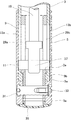
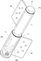
図1は、ヒンジアセンブリの正面図である。図2は、ヒンジアセンブリの平面図である。図3は、ヒンジアセンブリの断面図である。図4は、ヒンジアセンブリの要部拡大断面図である。図5は、ヒンジアセンブリの斜視図である。図6は、ヒンジアセンブリの動作状態の斜視図である。
玄関扉等への取り付けは、例えば図5の第1の結合板39を玄関の開口側にビスなどにより取り付け、第2の結合板41を玄関の扉側にビスなどにより取り付ける。
こうして、油圧抵抗が働く機能の備わったガススプリングを使用するため一つのヒンジアセンブリで自閉機能とスローダウン機能とを兼ね備えることができる。このため、自閉機能とスローダウン機能とを分離した構造に比較して構造をシンプルにし、安価に製造することもできる。
3 第1の外筒
5 第2の外筒
7 ガススプリング(付勢部材)
9 カム筒
11 カムピン(ピン)
13a、13b ガイド溝
17 シリンダ(基部)
19 ピストンロッド(可動部)
29a、29b カム溝
39 第1の結合板(第1の結合部)
41 第2の結合板(第2の結合部)
Claims (4)
- 第1、第2の外筒と付勢部材とカム筒とピンと第1、第2の結合部とを備えたヒンジアセンブリであって、
前記第1の外筒は、筒軸方向の一端側にガイド溝を有し、
前記第2の外筒は、前記第1の外筒の一端側に外嵌され、
前記付勢部材は、基部及び可動部を有して前記第1の外筒に同軸状に配置され、
前記基部は、前記第1の外筒の他端側に結合され、
前記可動部は、前記基部に対し押圧されるように移動し押圧が開放されると付勢力で移動を戻し、
前記カム筒は、前記第1の外筒の一端側に同軸状に配置されると共に前記第2の外筒に一体的に結合され、
前記カム筒は、前記ガイド溝に交差して一部が重なるカム溝を有し、
前記ピンは、前記ガイド溝及びカム溝が重なる部分で双方に嵌合し、
前記第1の外筒の他端側の外面に、取り付け用の前記第1の結合部が設けられると共に前記第2の外筒の外面に、取り付け用の前記第2の結合部が設けられ、
前記第2の結合部から受けた回転力で前記第2の外筒及び前記カム筒が前記第1の外筒に対して相対回転すると前記ピンが前記カム溝に駆動されつつ前記ガイド溝を一方向に移動して前記可動部の移動が行われ且つ前記押圧が開放されて前記付勢力により前記可動部の移動が戻ると前記ピンの移動が戻って前記カム溝を駆動し前記カム筒及び前記第2の外筒を介して前記第2の結合部の回転を戻すように連動構成された、
ことを特徴とするヒンジアセンブリ。 - 請求項1記載のヒンジアセンブリであって、
前記第2の外筒は、前記ガイド溝を覆う、
ことを特徴とするヒンジアセンブリ。 - 請求項1又は2記載のヒンジアセンブリであって、
前記付勢部材は、前記基部がシリンダであり、前記可動部がピストンロッドであり、ガスの圧縮反力により前記付勢力を発生するガススプリングである、
ことを特徴とするヒンジアセンブリ。 - 請求項1〜3の何れか1項に記載のヒンジアセンブリであって、
前記付勢部材は、前記付勢力による前記可動部の移動の戻り側にスローダウン機能部を備えた、
ことを特徴とするヒンジアセンブリ。
Priority Applications (1)
| Application Number | Priority Date | Filing Date | Title |
|---|---|---|---|
| JP2016247466A JP6765716B2 (ja) | 2016-12-21 | 2016-12-21 | ヒンジアセンブリ |
Applications Claiming Priority (1)
| Application Number | Priority Date | Filing Date | Title |
|---|---|---|---|
| JP2016247466A JP6765716B2 (ja) | 2016-12-21 | 2016-12-21 | ヒンジアセンブリ |
Publications (2)
| Publication Number | Publication Date |
|---|---|
| JP2018100543A JP2018100543A (ja) | 2018-06-28 |
| JP6765716B2 true JP6765716B2 (ja) | 2020-10-07 |
Family
ID=62715073
Family Applications (1)
| Application Number | Title | Priority Date | Filing Date |
|---|---|---|---|
| JP2016247466A Active JP6765716B2 (ja) | 2016-12-21 | 2016-12-21 | ヒンジアセンブリ |
Country Status (1)
| Country | Link |
|---|---|
| JP (1) | JP6765716B2 (ja) |
Families Citing this family (2)
| Publication number | Priority date | Publication date | Assignee | Title |
|---|---|---|---|---|
| CN108868412A (zh) * | 2018-07-16 | 2018-11-23 | 佛山市远阳五金制品有限公司 | 一种自动回位玻璃门安全夹 |
| CN114541900A (zh) * | 2022-01-21 | 2022-05-27 | 肇庆市高要区丰之泽卫浴五金有限公司 | 一种缓冲合页 |
Family Cites Families (3)
| Publication number | Priority date | Publication date | Assignee | Title |
|---|---|---|---|---|
| JP3713448B2 (ja) * | 2001-04-09 | 2005-11-09 | 和 佐波 | 緩衝機能付き自動閉扉機構及びその蝶番 |
| EP1342875A1 (en) * | 2002-03-07 | 2003-09-10 | Fu Luong Hi-Tech Co Ltd | Hinge device with a returning member for automatically closing an open door |
| ITVI20130245A1 (it) * | 2013-10-04 | 2015-04-05 | In & Tec Srl | Dispositivo a cerniera per porte, ante o similari |
-
2016
- 2016-12-21 JP JP2016247466A patent/JP6765716B2/ja active Active
Also Published As
| Publication number | Publication date |
|---|---|
| JP2018100543A (ja) | 2018-06-28 |
Similar Documents
| Publication | Publication Date | Title |
|---|---|---|
| JP5135232B2 (ja) | ヒンジ部分 | |
| US8127634B2 (en) | Driving device | |
| EP3222806A1 (en) | Door opening and closing device for vehicle | |
| US20090133222A1 (en) | Checker-Equipped Door Hinge Device for Vehicle | |
| JP7135814B2 (ja) | ローラユニット | |
| EP1624141B1 (en) | Clutch mechanism for locks | |
| RU2505655C2 (ru) | Фурнитура с приводом | |
| CN103958806A (zh) | 门操作器 | |
| CN112088237B (zh) | 用于驱动设备的制动装置 | |
| JP6765716B2 (ja) | ヒンジアセンブリ | |
| JP2019090258A (ja) | ドアチェック装置 | |
| CN102975775A (zh) | 车体 | |
| JP6345593B2 (ja) | 開閉体操作装置 | |
| CN1727625B (zh) | 汽车门控制装置 | |
| JP4510608B2 (ja) | 扉の制動装置 | |
| JP5782180B2 (ja) | ドアクローザ | |
| JP6884877B2 (ja) | 開閉体の開閉装置 | |
| JP2011121492A5 (ja) | ||
| JP6093204B2 (ja) | フリーストップドアヒンジクローザ | |
| JP2007145055A5 (ja) | ||
| EP1094185B1 (fr) | Charnière à freinage hydraulique | |
| JP2007145055A (ja) | 自動車のドアヒンジ装置 | |
| JP4829713B2 (ja) | 開口部閉鎖部材の制動装置及びそれを有する開口部閉鎖部材 | |
| WO2014114251A1 (zh) | 一种缓冲门折页 | |
| JP3550546B2 (ja) | ヒンジ機構 |
Legal Events
| Date | Code | Title | Description |
|---|---|---|---|
| A621 | Written request for application examination |
Free format text: JAPANESE INTERMEDIATE CODE: A621 Effective date: 20191107 |
|
| A977 | Report on retrieval |
Free format text: JAPANESE INTERMEDIATE CODE: A971007 Effective date: 20200820 |
|
| TRDD | Decision of grant or rejection written | ||
| A01 | Written decision to grant a patent or to grant a registration (utility model) |
Free format text: JAPANESE INTERMEDIATE CODE: A01 Effective date: 20200901 |
|
| A61 | First payment of annual fees (during grant procedure) |
Free format text: JAPANESE INTERMEDIATE CODE: A61 Effective date: 20200911 |
|
| R150 | Certificate of patent or registration of utility model |
Ref document number: 6765716 Country of ref document: JP Free format text: JAPANESE INTERMEDIATE CODE: R150 |
|
| R250 | Receipt of annual fees |
Free format text: JAPANESE INTERMEDIATE CODE: R250 |
|
| R250 | Receipt of annual fees |
Free format text: JAPANESE INTERMEDIATE CODE: R250 |
|
| R250 | Receipt of annual fees |
Free format text: JAPANESE INTERMEDIATE CODE: R250 |