JP6768356B2 - Shower head, faucet water supply equipment, hot water supply equipment with water discharge equipment structure and the same water discharge equipment structure - Google Patents
Shower head, faucet water supply equipment, hot water supply equipment with water discharge equipment structure and the same water discharge equipment structure Download PDFInfo
- Publication number
- JP6768356B2 JP6768356B2 JP2016112898A JP2016112898A JP6768356B2 JP 6768356 B2 JP6768356 B2 JP 6768356B2 JP 2016112898 A JP2016112898 A JP 2016112898A JP 2016112898 A JP2016112898 A JP 2016112898A JP 6768356 B2 JP6768356 B2 JP 6768356B2
- Authority
- JP
- Japan
- Prior art keywords
- water
- flow path
- electrolyzed
- electrolytic
- water discharge
- Prior art date
- Legal status (The legal status is an assumption and is not a legal conclusion. Google has not performed a legal analysis and makes no representation as to the accuracy of the status listed.)
- Active
Links
Images


Classifications
-
- A—HUMAN NECESSITIES
- A47—FURNITURE; DOMESTIC ARTICLES OR APPLIANCES; COFFEE MILLS; SPICE MILLS; SUCTION CLEANERS IN GENERAL
- A47K—SANITARY EQUIPMENT; ACCESSORIES THEREFOR, e.g. TOILET ACCESSORIES
- A47K3/00—Baths; Showers; Appurtenances therefor
- A47K3/28—Showers or bathing douches
-
- C—CHEMISTRY; METALLURGY
- C02—TREATMENT OF WATER, WASTE WATER, SEWAGE, OR SLUDGE
- C02F—TREATMENT OF WATER, WASTE WATER, SEWAGE, OR SLUDGE
- C02F1/00—Treatment of water, waste water, or sewage
- C02F1/46—Treatment of water, waste water, or sewage by electrochemical methods
-
- E—FIXED CONSTRUCTIONS
- E03—WATER SUPPLY; SEWERAGE
- E03C—DOMESTIC PLUMBING INSTALLATIONS FOR FRESH WATER OR WASTE WATER; SINKS
- E03C1/00—Domestic plumbing installations for fresh water or waste water; Sinks
- E03C1/02—Plumbing installations for fresh water
- E03C1/04—Water-basin installations specially adapted to wash-basins or baths
- E03C1/046—Adding soap, disinfectant, or the like in the supply line or at the water outlet
-
- A—HUMAN NECESSITIES
- A61—MEDICAL OR VETERINARY SCIENCE; HYGIENE
- A61H—PHYSICAL THERAPY APPARATUS, e.g. DEVICES FOR LOCATING OR STIMULATING REFLEX POINTS IN THE BODY; ARTIFICIAL RESPIRATION; MASSAGE; BATHING DEVICES FOR SPECIAL THERAPEUTIC OR HYGIENIC PURPOSES OR SPECIFIC PARTS OF THE BODY
- A61H33/00—Bathing devices for special therapeutic or hygienic purposes
- A61H33/02—Bathing devices for use with gas-containing liquid, or liquid in which gas is led or generated, e.g. carbon dioxide baths
-
- B—PERFORMING OPERATIONS; TRANSPORTING
- B05—SPRAYING OR ATOMISING IN GENERAL; APPLYING FLUENT MATERIALS TO SURFACES, IN GENERAL
- B05B—SPRAYING APPARATUS; ATOMISING APPARATUS; NOZZLES
- B05B1/00—Nozzles, spray heads or other outlets, with or without auxiliary devices such as valves, heating means
- B05B1/14—Nozzles, spray heads or other outlets, with or without auxiliary devices such as valves, heating means with multiple outlet openings; with strainers in or outside the outlet opening
- B05B1/18—Roses; Shower heads
Landscapes
- Health & Medical Sciences (AREA)
- Public Health (AREA)
- Water Supply & Treatment (AREA)
- Chemical & Material Sciences (AREA)
- Life Sciences & Earth Sciences (AREA)
- Hydrology & Water Resources (AREA)
- Engineering & Computer Science (AREA)
- Chemical Kinetics & Catalysis (AREA)
- Environmental & Geological Engineering (AREA)
- Organic Chemistry (AREA)
- Electrochemistry (AREA)
- General Chemical & Material Sciences (AREA)
- Epidemiology (AREA)
- General Health & Medical Sciences (AREA)
- Bathtubs, Showers, And Their Attachments (AREA)
- Nozzles (AREA)
- Domestic Plumbing Installations (AREA)
- Devices For Medical Bathing And Washing (AREA)
- Water Treatment By Electricity Or Magnetism (AREA)
Description
本発明は、吐水設備構造及び同吐水設備構造を備えたシャワーヘッド、蛇口水道設備、打たせ湯設備に関する。 The present invention relates to a water discharge facility structure and a shower head, a faucet water supply facility, and a hot water supply facility having the same water discharge facility structure.
従来、水道や給湯機等に接続され、湯水を吐水可能に構成した吐水設備が存在している。 Conventionally, there is a water discharge facility that is connected to a water supply or a water heater and is configured to be able to discharge hot water.
このような吐水設備の一例としては、例えば体を洗浄したり温める手段であり、多数の細孔から湯水を吐出させるシャワーが広く利用されている。 As an example of such a water discharge facility, for example, a means for washing or warming the body, and a shower that discharges hot water from a large number of pores is widely used.
シャワーは、吐出される無数の水滴を全身で浴びることで、身体表面に適度な刺激が与えられ、リフレッシュは勿論のこと、美容や安らぎの空間としても利用されている。 The shower is used as a space for beauty and comfort as well as refreshing because the body surface is appropriately stimulated by bathing the whole body with innumerable water droplets discharged.
特に昨今では、使用者の手肌などに有用な成分を含有させた機能水を吐出可能に構成したシャワーも提供されており、使用者がシャワータイムをより楽しむことができるよう工夫されている。 In particular, in recent years, showers that are configured to discharge functional water containing useful ingredients for the user's hands and the like have been provided, and are devised so that the user can enjoy the shower time more.
このような機能水の一例として、例えば、水を電気分解することで得られる酸性水やアルカリ水、またこれらが混じり合った水等の電解水が挙げられる。これら電解水は、それぞれ皮膚表面に対して収斂効果や制菌効果を発揮したり、皮膚表面の老廃物を効率的に除去できることが知られている。 Examples of such functional water include acidic water and alkaline water obtained by electrolyzing water, and electrolyzed water such as water in which these are mixed. It is known that each of these electrolyzed waters exerts an astringent effect and a bacteriostatic effect on the skin surface, and can efficiently remove waste products on the skin surface.
そこで、電解水による効果を体表面においても享受すべく、湯水に通電して電解可能に構成したシャワーヘッドが提供されている(例えば、特許文献1参照。)。 Therefore, in order to enjoy the effect of electrolyzed water on the body surface as well, a shower head configured to be electrolyzable by energizing hot water is provided (see, for example, Patent Document 1).
このシャワーヘッドによれば、電解水を全身で浴びることができ、皮膚の引き締めを行ったり、汚れを効率的に除去できるとしている。 According to this shower head, electrolyzed water can be bathed in the whole body, tightening the skin and efficiently removing dirt.
ところで、水に水素ガスを溶存させた水素水は、活性酸素消去能を有するとして、近年注目を浴びている。 By the way, hydrogen water in which hydrogen gas is dissolved in water has been attracting attention in recent years because it has an active oxygen scavenging ability.
この水素水は、水を電気分解して陰極側からの水素を水に含ませることで生成することも可能であり、前述のアルカリ水や、同アルカリ水と酸性水との混合水は、電解により生成した水素水としての側面も持ち合わせた機能水であると言える。なお、以下の説明において、水を電解することで水素を含ませた水を電解水素水と称し、中でも、水素ガスを含有する陰極側で生成されたアルカリ水をアルカリ電解水素水と称する。 This hydrogen water can also be generated by electrolyzing water and including hydrogen from the cathode side in the water, and the above-mentioned alkaline water and mixed water of the alkaline water and acidic water are electrolyzed. It can be said that it is a functional water that also has an aspect as hydrogen water generated by. In the following description, water containing hydrogen by electrolyzing water is referred to as electrolytic hydrogen water, and among them, alkaline water generated on the cathode side containing hydrogen gas is referred to as alkaline electrolytic hydrogen water.
しかしながら、上記従来のシャワー装置は、電解水素水を吐水するシャワー装置としての観点から言えば、電解水素水を所望する部位へ重点的に、且つ、高濃度で浴びせることが困難であった。 However, from the viewpoint of the shower device that discharges the electrolyzed hydrogen water, it is difficult for the above-mentioned conventional shower device to focus on the desired portion and to shower the electrolyzed hydrogen water at a high concentration.
また、これはシャワー装置に限られるものではなく、電解水素水を吐水可能に構成した吐水設備全般の問題点でもある。 Further, this is not limited to the shower device, but is also a problem of the whole water discharge facility configured to be capable of discharging electrolytic hydrogen water.
本発明は、斯かる事情に鑑みてなされたものであって、電解水素水を所望する部位へ重点的に、且つ、高濃度で吐出することのできる吐水設備構造を提供する。また、本発明では、同吐水設備構造を備えたシャワーヘッドや、同吐水設備構造を備えた蛇口水道設備、同吐水設備構造を備えた打たせ湯設備についても提供する。 The present invention has been made in view of such circumstances, and provides a water discharge facility structure capable of discharging electrolyzed hydrogen water to a desired portion in a focused manner and at a high concentration. The present invention also provides a shower head having the same water discharge facility structure, a faucet water supply facility having the same water discharge facility structure, and a hot water tapping facility having the same water discharge facility structure.
上記従来の課題を解決するために、本発明に係る吐水設備構造では、(1)給水流路より供給される湯水を吐水部から吐出する吐水設備の構造において、前記給水流路にて前記湯水を分流する分流部と、分流部にて分流された一方の湯水を電解して電解水素水と成し、同電解水素水を前記吐水部へ導く電解流路と、分流部にて分流された他方の湯水を電解せずに非電解水の状態で前記吐水部へ導く通水流路と、を備え、前記吐水部には、前記電解流路の下流にて電解水素水を吐出する電解水素水吐出領域と、前記通水流路の下流にて非電解水を吐出する非電解水吐出領域と、がそれぞれ別個に形成されていることとした。 In order to solve the above-mentioned conventional problems, in the water discharge facility structure according to the present invention, (1) in the structure of the water discharge facility that discharges the hot water supplied from the water supply flow path from the water discharge unit, the hot water in the water supply flow path. The split stream section and one of the hot water splits at the split stream section are electrolyzed to form electrolytic hydrogen water, and the electrolytic hydrogen water is split into the electrolytic flow path leading to the water discharge section and the diversion section. Electrolyzed hydrogen water that is provided with a water passage that guides the other hot water to the spouting portion in a non-electrolyzed state without electrolyzing the hot water, and discharges electrolytic hydrogen water downstream of the electrolytic flow path to the spouting portion. It was decided that the discharge region and the non-electrolyzed water discharge region for discharging the non-electrolyzed water downstream of the water flow path are separately formed.
また、本発明に係る吐水設備構造では、以下の点にも特徴を有する。
(2)湯水の流通により起電する起電部を前記給水流路に備え、同起電部にて生成した電力により前記電解流路にて湯水の電解を行うこと。
(3)前記電解水素水吐出領域と前記非電解水吐出領域との境界には、吐出された前記電解水素水と前記非電解水とが飛程において混在するのを防止する区画手段が設けられていること。
(4)前記電解水素水吐出領域に穿設された吐出孔と、前記非電解水吐出領域に穿設された吐出孔は、相互に離隔する方向へ吐出する角度で穿設されていること。
(5)前記電解流路は、アルカリ性の電解水素水を生成する陰極が配置された陰極流路と、酸性水を生成する陽極が配置された陽極流路とを備え、両流路は相互の流通を規制する区画壁にて仕切られており、前記電解水素水吐出領域には、アルカリ電解水素水を吐出するアルカリ電解水素水吐出領域と、酸性水を吐出する酸性水吐出領域とが、それぞれ別個に形成されていること。
(6)前記通水流路にマイクロバブル発生部を備えること。
(7)前記電解流路にマイクロバブル発生部を備えること。
In addition, the water discharge facility structure according to the present invention is also characterized by the following points.
(2) A power generating section for generating electricity by the flow of hot water is provided in the water supply flow path, and hot water is electrolyzed in the electrolytic flow path by the electric power generated by the power generating section.
(3) At the boundary between the electrolyzed hydrogen water discharge region and the non-electrolyzed water discharge region, a partition means for preventing the discharged electrolyzed hydrogen water and the non-electrolyzed water from being mixed in the flight is provided. That you are.
(4) The discharge hole bored in the electrolyzed hydrogen water discharge region and the discharge hole bored in the non-electrolyzed water discharge region shall be bored at an angle of discharging in a direction away from each other.
(5) The electrolytic flow path includes a cathode flow path in which a cathode for producing alkaline electrolytic hydrogen water is arranged and an anode flow path in which an anode for generating acidic water is arranged, and both flow paths are mutually exclusive. It is partitioned by a partition wall that regulates distribution, and in the electrolytic hydrogen water discharge region, an alkaline electrolytic hydrogen water discharge region for discharging alkaline electrolytic hydrogen water and an acidic water discharge region for discharging acidic water are respectively. Must be formed separately.
(6) The water flow path is provided with a micro-bubble generating portion.
(7) The electrolytic flow path is provided with a microbubble generating portion.
また、本発明に係るシャワーヘッドでは、(8)上記(1)〜(7)いずれかの吐水設備構造を備えることとした。 Further, the shower head according to the present invention is provided with (8) a water discharge facility structure according to any one of (1) to (7) above.
また、本発明に係る蛇口水道設備では、(9)上記(1)〜(7)いずれかの吐水設備構造を備えることとした。 Further, the faucet water supply facility according to the present invention is provided with (9) the water discharge facility structure according to any one of (1) to (7) above.
また、本発明に係る打たせ湯設備では、(10)上記(1)〜(7)いずれかの吐水設備構造を備えることとした。 Further, the hot water facility according to the present invention is provided with (10) the water discharge facility structure according to any one of (1) to (7) above.
本発明に係る吐水設備構造によれば、給水流路より供給される湯水を吐水部から吐出する吐水設備の構造において、前記給水流路にて前記湯水を分流する分流部と、分流部にて分流された一方の湯水を電解して電解水素水と成し、同電解水素水を前記吐水部へ導く電解流路と、分流部にて分流された他方の湯水を電解せずに非電解水の状態で前記吐水部へ導く通水流路と、を備え、前記吐水部には、前記電解流路の下流にて電解水素水を吐出する電解水素水吐出領域と、前記通水流路の下流にて非電解水を吐出する非電解水吐出領域と、がそれぞれ別個に形成されていることとしたため、電解水素水を所望する部位へ重点的に、且つ、高濃度で吐出することのできる吐水設備構造を提供することができる。 According to the water discharge facility structure according to the present invention, in the structure of the water discharge facility that discharges the hot water supplied from the water supply flow path from the water discharge section, the diversion section that divides the hot water in the water supply flow path and the diversion section One of the separated hot water is electrolyzed to form electrolytic hydrogen water, and the electrolytic flow path that guides the electrolytic hydrogen water to the water discharge section and the other hot water that has been split at the diversion section are not electrolyzed. The water discharge section is provided with a water flow path leading to the water discharge section in the above state, and the water discharge section has an electrolytic hydrogen water discharge region for discharging electrolytic hydrogen water downstream of the electrolytic flow path and downstream of the water flow path. Since the non-electrolyzed water discharge region for discharging the non-electrolyzed water is formed separately, the water discharge facility can discharge the electrolyzed hydrogen water to a desired part in a concentrated manner and at a high concentration. The structure can be provided.
また、湯水の流通により起電する起電部を前記給水流路に備え、同起電部にて生成した電力により前記電解流路にて湯水の電解を行うこととすれば、分流前の大流量の湯水で発電しつつ、分流後の少ない湯水をこの十分な電力により電解することができ、電解水素水中に含まれる水素の高濃度化をより堅実なものとすることができる。 Further, if a power generating section for generating electricity by the flow of hot water is provided in the water supply flow path and the hot water is electrolyzed in the electrolytic flow path by the electric power generated by the power generating section, the amount of hot water before splitting is large. While generating electricity with hot water of a flow rate, it is possible to electrolyze a small amount of hot water after diversion with this sufficient electric power, and it is possible to make the concentration of hydrogen contained in the electrolyzed hydrogen water more solid.
また、前記電解水素水吐出領域と前記非電解水吐出領域との境界には、吐出された前記電解水素水と前記非電解水とが飛程において混在するのを防止する区画手段が設けられていることとすれば、非電解水により電解水素水が希釈されてしまうことを防止でき、電解水素水を所望する部位へ高濃度で吐出することができる。 Further, at the boundary between the electrolyzed hydrogen water discharge region and the non-electrolyzed water discharge region, a partition means for preventing the discharged electrolyzed hydrogen water and the non-electrolyzed water from being mixed in the flight is provided. If this is the case, it is possible to prevent the electrolyzed hydrogen water from being diluted by the non-electrolyzed water, and it is possible to discharge the electrolyzed hydrogen water to a desired portion at a high concentration.
また、前記電解水素水吐出領域に穿設された吐出孔と、前記非電解水吐出領域に穿設された吐出孔は、相互に離隔する方向へ吐出する角度で穿設されていることとすれば、非電解水により電解水素水が希釈されてしまうことをより堅実に防止することができる。 Further, the discharge holes bored in the electrolyzed hydrogen water discharge region and the discharge holes bored in the non-electrolyzed water discharge region are bored at an angle of discharging in a direction away from each other. For example, it is possible to more steadily prevent the electrolyzed hydrogen water from being diluted by the non-electrolyzed water.
また、前記電解流路は、アルカリ性の電解水素水を生成する陰極が配置された陰極流路と、酸性水を生成する陽極が配置された陽極流路とを備え、両流路は相互の流通を規制する区画壁にて仕切られており、前記電解水素水吐出領域には、アルカリ電解水素水を吐出するアルカリ電解水素水吐出領域と、酸性水を吐出する酸性水吐出領域とが、それぞれ別個に形成されていることとすれば、更に高濃度の水素を含有し、しかも皮膚表面の老廃物除去効果に優れたアルカリ電解水素水を酸性水や非電解水により希釈されてしまうことなく吐出させることができる。 Further, the electrolytic flow path includes a cathode flow path in which a cathode for generating alkaline electrolyzed hydrogen water is arranged and an anode flow path in which an anode for generating acidic water is arranged, and both flow paths are mutually circulated. In the electrolytic hydrogen water discharge region, an alkaline electrolyzed hydrogen water discharge region for discharging alkaline electrolyzed hydrogen water and an acidic water discharge region for discharging acidic water are separated from each other. If it is formed in, alkaline electrolyzed hydrogen water containing a higher concentration of hydrogen and having an excellent effect of removing waste products on the skin surface is discharged without being diluted by acidic water or non-electrolyzed water. be able to.
また、前記通水流路にマイクロバブル発生部を備えることとすれば、湯水吐出領域より吐出される湯水についてもマイクロバブルによる機能性を付与することができ、洗浄効果や美容効果をより高めることができる。 Further, if the water flow path is provided with a micro-bubble generating portion, it is possible to impart the functionality of the micro-bubbles to the hot water discharged from the hot water discharge region, and it is possible to further enhance the cleaning effect and the beauty effect. it can.
また、前記電解流路にマイクロバブル発生部を備えることとすれば、電解水素水にマイクロバブルによる機能性を付与することができ、洗浄効果や美容効果をより高めることができる。特に電解流路の下流側にマイクロバブル発生手段を備えることとすれば、水素の溶解をより高効率で行わせることができる。 Further, if the electrolytic flow path is provided with the micro-bubble generating portion, the electrolytic hydrogen water can be imparted with the functionality due to the micro-bubbles, and the cleaning effect and the beauty effect can be further enhanced. In particular, if the microbubble generating means is provided on the downstream side of the electrolytic flow path, hydrogen can be dissolved with higher efficiency.
また、上述の吐水設備構造を備えたシャワーヘッドとすれば、水素水を所望する部位へ重点的に、且つ、高濃度で浴びせることのできるシャワーヘッドを提供することができる。 Further, if the shower head is provided with the above-mentioned water discharge facility structure, it is possible to provide a shower head capable of spraying hydrogen water on a desired portion in a concentrated manner and at a high concentration.
また、上述の吐水設備構造を備えた蛇口水道設備とすれば、水素水を所望する部位へ重点的に、且つ、高濃度で浴びせることのできる蛇口水道設備を提供することができる。 Further, if the faucet water supply facility having the above-mentioned water discharge facility structure is provided, it is possible to provide a faucet water supply facility capable of spraying hydrogen water on a desired portion in a concentrated manner and at a high concentration.
また、上述の吐水設備構造を備えた打たせ湯設備とすれば、水素水を所望する部位へ重点的に、且つ、高濃度で浴びせることのできる打たせ湯設備を提供することができる。 Further, if the hot water spouting facility having the above-mentioned water spouting facility structure is provided, it is possible to provide a hot water tapping facility capable of spraying hydrogen water on a desired portion in a concentrated manner and at a high concentration.
本発明は、給水流路より供給される湯水を吐水部から吐出する吐水設備の構造において、前記給水流路にて前記湯水を分流する分流部と、分流部にて分流された一方の湯水を電解して電解水素水と成し、同電解水素水を前記吐水部へ導く電解流路と、分流部にて分流された他方の湯水を電解せずに非電解水の状態で前記吐水部へ導く通水流路と、を備え、前記吐水部には、前記電解流路の下流にて電解水素水を吐出する電解水素水吐出領域と、前記通水流路の下流にて非電解水を吐出する非電解水吐出領域と、がそれぞれ別個に形成されていることを特徴とする吐水設備構造を提供するものである。 The present invention has a structure of a water discharge facility that discharges hot water supplied from a water supply flow path from a water discharge section, in which a diversion section that diverts the hot water in the water supply flow path and one of the hot water that is split in the diversion section are separated. Electrolyze to form electrolyzed hydrogen water, and the electrolyzed flow path that guides the electrolyzed hydrogen water to the spouting part and the other hot water that has been separated at the diversion part are not electrolyzed to the spouting part in the state of non-electrolyzed water. It is provided with a water flow path for guiding, and the water discharge portion has an electrolytic hydrogen water discharge region for discharging electrolytic hydrogen water downstream of the electrolytic flow path and non-electrolyzed water is discharged downstream of the water flow path. Provided is a water discharge facility structure characterized in that a non-electrolyzed water discharge region and a non-electrolyzed water discharge region are formed separately.
前述したように、吐水設備の一つである従来のシャワー装置にあっては、使用者は電解水素水を浴びることは可能であるものの、極めて水素濃度の低い電解水素水でしか、水素の活性酸素消去効果を享受することはできず、また、使用者が所望する被施療部位に対してピンポイントで浴びせることは困難であった。 As mentioned above, in the conventional shower device, which is one of the water discharge facilities, the user can be exposed to the electrolytic hydrogen water, but the hydrogen activity is only in the electrolytic hydrogen water having an extremely low hydrogen concentration. It was not possible to enjoy the oxygen scavenging effect, and it was difficult to pinpoint the treatment site desired by the user.
そこで本発明では、給水流路より供給された湯水を分流してその一部に対して電解を施し、電解により生成した電解水素水を一般の湯水、すなわち非電解水とは別個の吐出領域より吐出させることとしている。 Therefore, in the present invention, the hot water supplied from the water supply flow path is divided and a part of the hot water is electrolyzed, and the electrolyzed hydrogen water generated by the electrolysis is discharged from a general hot water, that is, a discharge region separate from the non-electrolyzed water. It is supposed to be discharged.
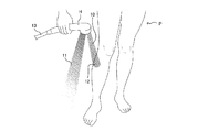
従って、図1に示すように、使用者Pは、非電解水11とは別個に吐出される電解水素水10を、非電解水11により希釈されることなく被施療部位(図1においては、すね12やふくらはぎ等)に対し、高濃度かつピンポイントで浴びせることができ、高濃度水素による活性酸素消去効果を享受して手肌や美容上気になる部位の改善を行うことができる。
Therefore, as shown in FIG. 1, the user P uses the electrolyzed
以下、本実施形態に係る吐水設備構造及び同吐水設備構造を備えたシャワーヘッド、蛇口水道設備、打たせ湯設備について、図面を参照しながら具体的に説明する。 Hereinafter, the shower head, the faucet water supply facility, and the tapping hot water facility having the water discharge facility structure and the water discharge facility structure according to the present embodiment will be specifically described with reference to the drawings.
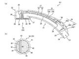
図2は、第1の実施形態に係る吐水設備構造を備えたシャワーヘッドH1の構成を示した説明図であって、図2(a)はシャワーヘッドH1の長手方向断面を示しており、図2(b)はシャワーヘッドH1に備えられた散水部22の底面部34を示している。
FIG. 2 is an explanatory view showing the configuration of the shower head H1 provided with the water discharge facility structure according to the first embodiment, and FIG. 2A shows a longitudinal cross section of the shower head H1. Reference numeral 2 (b) shows a
シャワーヘッドH1は、図2(a)に示すように、使用者Pが把持する把持部21と、同把持部21の先端側に配置された散水部22とで構成している。
As shown in FIG. 2A, the shower head H1 is composed of a
把持部21は、中空の略筒状としてその内部に流路23を形成している。また、把持部21の基端部外周には、シャワーヘッドH1に湯水を供給するための給水ホース13(図1参照)を螺合可能とする雄ネジ部24が形成されおり、給水ホース13より供給された湯水を流路23に通水可能としている。
The
流路23には、その中途部から散水部22にかけて、流路23に供給された湯水を区画分流する分流壁25が配設されており、その基端側端部近傍を分流部26としている。
The
分流部26よりも上流側の流路23は、分流部26よりも下流側の流路23であって並列して設けられた複数の流路より構成される分岐流路27に湯水を供給するための給水流路28としている。
The
特に本実施形態では、分岐流路27にて電解水素水を生成する電力を得るための給電機構29が把持部21に備えられており、給水流路28には、同給水流路28を流通する湯水により回転力を得るためのプロペラ29aが配設されている。
In particular, in the present embodiment, the
具体的には、給水流路28の通水により回転するプロペラ29aの回転力は、把持部21の基端側に形成した肉厚形成部30内の発電機29bに伝達され、発電機29bにて生成された電力は、制御部29dを介して分岐流路27へ供給されるよう構成している。すなわち、プロペラ29aと発電機29bとで起電部29cを構成しており、給電機構29は、起電部29cと制御部29dとで構成している。
Specifically, the rotational force of the
分岐流路27は、分流壁25を隔てて通水流路31と電解流路32とで構成している。
The
通水流路31は、分流部26にて分流された湯水を電解せず、非電解水11として散水部22へ導く流路である。
The
電解流路32は、分流部26にて分流された湯水を電解して電解水素水10と成し、同電解水素水10を散水部22へ導く流路であり、その内周壁面には、対向状態に配設された陰極板33a及び陽極板33bよりなる一対の電極板33が配設されている。
The
陰極板33aは、前述の給電機構29の制御部29dに配設された陰極端子に電気的に接続され、また、陽極板33bは制御部29dの陽極端子に電気的にに接続されており、陰極板33aは陽極板33bに対して相対的に低電位(陽極板33bは陰極板33aに対して相対的に高電位)に電圧が印加されるよう構成し、電極間で電解流路32を流通する湯水を介して通電し、電解を行って、陰極板33aの表面にて発生する水素ガスを溶解させて電解水素水10が生成されるようにしている。
The
散水部22は、中空で略円柱状に形成された吐水部として機能する部位であり、図2(b)に示すように、その底面部34を吐水面としている。
The
また、散水部22の内部には、仕切壁35を隔てて電解水素水流入空間36と非電解水流入空間37とが形成されている。
Further, inside the
電解水素水流入空間36は、電解流路32にて生成された電解水素水10が流入する空間であり、電解流路32と連通させて形成している。
The electrolytic hydrogen
また、電解水素水流入空間36に対応する底面部34は、電解水素水流入空間36内に流入した電解水素水10が吐出される電解水素水吐出孔38を複数穿設して電解水素水吐出領域39としている。
Further, the
非電解水流入空間37は、通水流路31を流通する非電解水11が流入する空間であり、通水流路31と連通させて形成している。
The non-electrolyzed
また、非電解水流入空間37に対応する底面部34は、非電解水流入空間37内に流入した非電解水11が吐出される非電解水吐出孔40を複数穿設して非電解水吐出領域41としている。
Further, the
ここで、図2(a)に示すように、底面部34に穿設された電解水素水吐出孔38及び非電解水吐出孔40は、相互に離隔する方向へ吐出する角度で穿設されている。
Here, as shown in FIG. 2A, the electrolyzed hydrogen
また、図2(b)に示すように、電解水素水吐出領域39と非電解水吐出領域41との境界には、吐水孔が穿設されていない区画領域42が区画手段として形成されており、電解水素水吐出領域39より吐出された電解水素水10と、非電解水吐出領域41より吐出された非電解水11とが飛程において混在するのを防止している。
Further, as shown in FIG. 2B, a
そして、このような構成を備えたシャワーヘッドH1によれば、雄ネジ部24に接続された給水ホース13より湯水が供給されると、湯水は給水流路28内に流入し、給水流路28内に配設されたプロペラ29aを回転させる。
Then, according to the shower head H1 having such a configuration, when hot water is supplied from the
プロペラ29aの回転力により発電機29bでは電力が生成され、制御部29dを介して陰極板33a及び陽極板33bに所定の電圧が印加される。
Electric power is generated in the generator 29b by the rotational force of the
次いで、給水流路28の湯水は分流部26に至り、通水流路31へ流入する湯水と電解流路32へ流入する湯水とに分流される。
Next, the hot water of the water
通水流路31に流入した湯水は、電解を受けることなく非電解水11として散水部22の非電解水流入空間37へ至り、底面部34の非電解水吐出領域41より非電解水吐出孔40を介して吐出される。
The hot water flowing into the
一方、電解流路32へ流入した湯水は、対向配置された電極板33間を流れることで電解され、陰極板33aの表面にて生じた水素ガスが溶解して電解水素水10となる。
On the other hand, the hot water flowing into the
電解流路32にて生成された電解水素水10は、散水部22の電解水素水流入空間36へ至り、底面部34の電解水素水吐出領域39より電解水素水吐出孔38を介して吐出されることとなる。
The
ここで、本実施形態に係るシャワーヘッドH1について特筆すべき点の一つとして、給水流路28の下流にて湯水を分流する分流部26と、分流部26にて分流された一方の湯水を電解して電解水素水10と成し、同電解水素水10を散水部22へ導く電解流路32と、分流部26にて分流された他方の湯水を電解せずに非電解水11として散水部22へ導く通水流路31と、を備えている点が挙げられる。
Here, as one of the points to be noted about the shower head H1 according to the present embodiment, the
すなわち、シャワーヘッドH1では、電解流路32へ流入する単位時間あたりの湯水の量は、給水流路28を流通する単位時間あたりの湯水の量よりも少ない量となるように構成している。
That is, the shower head H1 is configured such that the amount of hot water flowing into the
従って、給水流路28を流れる大流量の湯水により大きな電力を得つつ、電解流路32に流入した相対的に小流量の湯水を大きな電力で強力に電解することができ、高濃度に水素ガスを溶存させた電解水素水10を生成することができる。
Therefore, it is possible to strongly electrolyze the relatively small flow rate of hot water flowing into the
また、分流部26における湯水の分流割合は、電解流路32に流入する単位時間あたりの湯水の量が、給水流路28を流れる単位時間あたりの湯水の量よりも少なくなれば特に限定されるものではなく、適宜変更可能である。
Further, the diversion ratio of hot water in the
例えば、図2(a)において示したように、分流部26における湯水の分流割合を、電解流路32に流入する単位時間あたりの湯水の量が、通水流路31に流入する単位時間あたりの湯水の量に比して少なくなるように構成しても良い。
For example, as shown in FIG. 2A, the diversion ratio of hot water in the
このような構成とすることにより、水素ガスをより濃厚に含有させた電解水素水10を吐出させることができ、手肌の改善や美容効果の更なる向上を期待することができる。
With such a configuration, the electrolyzed
また、図2(a)において示したように、分流壁25で隔てつつも通水流路31と電解流路32とを並行して設け、通水流路31を流れる非電解水11と電解流路32を流れる電解水素水10との間で熱の授受ができるように構成しても良い。
Further, as shown in FIG. 2A, the
特に、シャワーヘッドH1では、分流壁25側に陰極板33aを配設しており、陰極板33aにおいて電解により生じた熱が分流壁25を介して非電解水11に伝達されるよう構成している。付言するならば、通水流路31を流れる非電解水11を冷却媒とする陰極板33aの冷却構造を備えている。
In particular, in the shower head H1, a
従って、水素ガスの水への溶解は温度が低いほど促進されるところ、上記構成によれば、陰極板33aの表面にて生じた水素ガスの溶解効率を向上させることができ、より高濃度の電解水素水10を生成することができる。このことは特に、給水流路28を流れる大量の湯水で発生させた大電流により、比較的少量の湯水を電解して電解水素水10を生成する場合には、大電流による電解によって電解水素水10の温度が昇温しやすいため、水素ガスの溶存量を向上させる上で極めて有用な構成であるといえる。
Therefore, the dissolution of hydrogen gas in water is promoted as the temperature is lower. However, according to the above configuration, the dissolution efficiency of hydrogen gas generated on the surface of the
また、陰極板33aが金属など熱伝導性の高い材料で形成されている場合には、電解による熱で昇温した電解流路32を流れる電解水素水10から、通水流路31を流れる非電解水11との熱勾配により熱を奪う受熱板として機能させることができ、分流壁25を介して電解水素水10の温度を低下させることも可能である。また、分流壁25は、熱伝達が可能な程度の厚みであれば、通常、シャワーヘッドに用いられる一般的な樹脂にて形成しても良いが、高熱伝導性の樹脂を用いるのも一案である。
When the
また、本実施形態に係るシャワーヘッドH1についての更なる特筆すべき点として、散水部22の底面部34には、電解流路32の下流にて電解水素水10を吐出する電解水素水吐出領域39と、通水流路31の下流にて非電解水11を吐出する非電解水吐出領域41と、をそれぞれ別個に形成している点が挙げられる。
Further, as a further noteworthy point about the shower head H1 according to the present embodiment, the
このような構成を備えることにより、電解水素水吐出孔38より吐出される電解水素水10と非電解水吐出領域41より吐出される非電解水11とが混合されて電解水素水10が希釈されてしまうことを防止でき、高濃度の水素ガスを含有した電解水素水10による効果を堅実に享受することが可能となる。
By providing such a configuration, the
しかも、電解水素水吐出領域39と非電解水吐出領域41との2つの領域は、それぞれ別個に形成しているため、電解水素水吐出領域39より吐出された電解水素水10を、使用者が所望する被施療部位に対してピンポイントで浴びせることができ、より良い皮膚改善効果や美容効果を生起させることができる。
Moreover, since the two regions of the electrolytic hydrogen
また、底面部34の電解水素水吐出孔38と非電解水吐出領域41との境界には区画領域42を設けているため、被施療部位に対してピンポイントで電解水素水10を浴びせやすく、また電解水素水10と非電解水11とが混ざり合って希釈化されることをより堅実に防止することができる。
Further, since the
更には、電解水素水吐出孔38と非電解水吐出孔40とを、相互に離隔する方向へ吐出する角度で穿設することで、電解水素水10と非電解水11とが飛程において混在することを防止して、電解水素水10の希釈化を更に防止することができる。なお、上述したシャワーヘッドH1の基本構成や付加的構成は、後述する他の実施形態においても採用可能であり、これらの効果を享受し得るのは勿論である。
Further, by drilling the electrolytic hydrogen
次に、第2の実施形態に係る吐水設備構造を備えたシャワーヘッドH1aについて、図3を参照しながら説明する。図3(a)はシャワーヘッドH1aの長手方向断面を示しており、図3(b)はシャワーヘッドH1aに備えられた吐出面20を示している。なお、以下において、前述のシャワーヘッドH1と同様の構成については、同じ符号を付して説明を省略する。
Next, the shower head H1a provided with the water discharge facility structure according to the second embodiment will be described with reference to FIG. FIG. 3A shows a longitudinal cross section of the shower head H1a, and FIG. 3B shows a
シャワーヘッドH1aは、シャワーヘッドH1と略同様の構成を備えており、電解水素水10と非電解水11とを吐出可能に構成したものであるが、通水流路31の中途部にバルブ体14を介設した点や、電解流路32の下流側流路終端部に定流量弁15を配設した点において構成を異にしている。
The shower head H1a has substantially the same configuration as the shower head H1 and is configured so that the electrolyzed
図3(a)に示す通水流路31の中途に介設されたバルブ体14は、使用者が指先などでボタン14aを押下することにより、通水流路31の通水・止水を操作可能とするものである。
The
具体的には、バルブ体14の内部には、通水孔14cが穿設されたボール体14bが収容されており、ボタン14aが押下される毎に略90度回転し、ボールバルブの如く通水・止水が行われる。すなわち、バルブ体14は、通水流路流通制御手段として機能する。
Specifically, a
一方、電解流路32の終端部に配設された定流量弁15は、バルブ体14が閉状態の時に、同バルブ体14が開状態の時と略同量の電解水素水の流通に規制する弁体である。
On the other hand, the
そして、このような構成を備えたシャワーヘッドH1aによれば、給水ホース13より供給され、給水流路28を経て分流部26に至った湯水は、電解流路32と通水流路31とに分流される。
Then, according to the shower head H1a having such a configuration, the hot water supplied from the
通水流路31へ流入した湯水は、バルブ体14が開状態であれば、電解を受けることなく非電解水11として散水部22の非電解水流入空間37へ至り、底面部34の非電解水吐出領域41より非電解水吐出孔40を介して吐出される。
If the
一方、電解流路32へ流入した湯水は、対向配置された電極板33間を流れることで電解され、陰極板33aの表面にて生じた水素ガスが溶解して電解水素水10となり、定流量弁15を介して散水部22の電解水素水流入空間36へ至り、底面部34の電解水素水吐出領域39、すなわち、底面部34の外周縁近傍領域より電解水素水吐出孔38を介して吐出されることとなる。
On the other hand, the hot water flowing into the
ここで、使用者によりバルブ体14のボタン14aが押下され、バルブ体14が閉状態となると、分流部26における通水流路31への湯水の流入はなくなり、非電解水吐出領域41からの非電解水11の吐出は停止する。
Here, when the
従って、吐出面20からは電解水素水吐出領域39からの電解水素水10のみが吐出されることとなり、吐出後に非電解水11と混じり合って希釈されてしまうことを堅実に防止することができる。
Therefore, only the electrolyzed
このとき電解流路32では、通水流路31が止水されたことに伴い、本来であれば単位時間あたりの流量が増加するところであるが、定流量弁15によりその流量は通水流路31が開状態のときと略同流量に保たれる。
At this time, in the
従って、電解流路32へ流入した湯水は電極板33により十分に電解を受ける時間を確保することができ、電解水素水吐出領域39より吐出される電解水素水の溶存水素濃度が極端に低下してしまうことを防止することができる。
Therefore, the hot water flowing into the
また、電解流路32では、バルブ体14が開状態の時と比較して、高い水圧が付与されることとなる。従って、水素の溶解効率を更に向上させることができる。
Further, in the
なお、本実施形態では、通水流路流通制御手段として手動式のバルブ体14を用いて通水流路31の通水・止水を操作するようにしたがこれに限定されるものではなく、例えば電磁バルブ等を用いて電気的に通水流路31の通水・止水を操作可能としても良い。
In the present embodiment, the
次に、第3の実施形態に係る吐水設備構造を備えたシャワーヘッドH2について、図4を参照しながら説明する。図4(a)はシャワーヘッドH2の長手方向断面を示しており、図4(b)はシャワーヘッドH2に備えられた吐出面20を示している。
Next, the shower head H2 provided with the water discharge facility structure according to the third embodiment will be described with reference to FIG. FIG. 4A shows a longitudinal cross section of the shower head H2, and FIG. 4B shows a
シャワーヘッドH2は、シャワーヘッドH1と略同様の構成を備えており、電解水素水10と非電解水11とを吐出可能に構成したものであるが、分流壁を円筒状として分岐流路27を二重管状に構成した点や、通水流路31にマイクロバブル発生部を設けて非電解水をマイクロバブル水として吐出可能に構成した点、底面部34に形成した各吐出領域の領域形状において構成を異にしている。
The shower head H2 has substantially the same configuration as the shower head H1 and is configured so that the electrolyzed
図4(a)に示すように、シャワーヘッドH2における流路23には、その中途部から散水部22にかけて、略円筒状の筒状分流壁50が二重管状に配設されており、その基端側端部近傍を分流部26としている。
As shown in FIG. 4A, a substantially cylindrical
また、筒状分流壁50の内側を通水流路31とする一方、筒状分流壁50の外周面と把持部21の内周面との間に形成された横断面においてドーナツ状の間隙を電解流路32としている。
Further, while the
筒状分流壁50の中途部には、内方へ肉厚状に形成してなるベンチュリ構造部51が備えられており、通水流路31は一部狭窄した形状としている。
A
また、筒状分流壁50には、把持部21の表面にかけて細管状の吸気管52が形成されており、通水流路31へ流入した湯水に対して空気を導入可能としている。この吸気管52は、ベンチュリ構造部51と共に、非電解水11としてのマイクロバブル水を生成するマイクロバブル発生部53として機能する。
Further, a thin
電解流路32は、分流部26にて分流された湯水を電解して電解水素水10と成し、同電解水素水10を散水部22へ導く流路であり、筒状分流壁50の外周面に配設された陰極板33aと、把持部21の内周面に配設された陽極板33bとよりなる一対の電極板33が配設されている。
The
これら陰極板33a及び陽極板33bは、前述のシャワーヘッドH1と同様、給電機構29の制御部29dに配設された陰極端子や陰極端子に電気的に接続されており、陰極板33aは陽極板33bに対して相対的に低電位(陽極板33bは陰極板33aに対して相対的に高電位)に電圧が印加されるよう構成し、電極間で電解流路32に流入した湯水を介して通電し、電解を行って、陰極板33aの表面にて発生する水素ガスを溶解させて電解水素水10が生成されるようにしている。
Similar to the shower head H1, the
散水部22は、その内部を仕切壁35で隔て、電解流路32と連通する電解水素水流入空間36と、通水流路31と連通するマイクロバブル水流入空間54とが形成されている。
The
また、電解水素水流入空間36に対応する底面部34は、電解水素水流入空間36内に流入した電解水素水10が吐出される電解水素水吐出孔38を複数穿設して電解水素水吐出領域39とする一方、マイクロバブル水流入空間54に対応する底面部34には、マイクロバブル水流入空間54内に流入したマイクロバブル水が吐出されるマイクロバブル水吐出孔55を複数穿設して、非電解水吐出領域としてのマイクロバブル水吐出領域56を形成している。
Further, the
また、図4(b)に示すように、電解水素水吐出領域39とマイクロバブル水吐出領域56との境界には、吐水孔が穿設されていない区画領域42が同心円状に形成されており、電解水素水吐出領域39より吐出された電解水素水10と、マイクロバブル水吐出領域56より吐出されたマイクロバブル水とが飛程において混在するのを防止している。
Further, as shown in FIG. 4B, a
そして、このような構成を備えたシャワーヘッドH2によれば、給水ホース13より供給され、給水流路28を経て分流部26に至った湯水は、電解流路32と通水流路31とに分流される。
Then, according to the shower head H2 having such a configuration, the hot water supplied from the
電解流路32へ流入した湯水は、対向配置された電極板33間を流れることで電解され、陰極板33aの表面にて生じた水素ガスが溶解して電解水素水10となり、散水部22の電解水素水流入空間36へ至り、底面部34の電解水素水吐出領域39、すなわち、底面部34の外周縁近傍領域より電解水素水吐出孔38を介して吐出されることとなる。
The hot water flowing into the
一方、通水流路31に流入した湯水は、吸気管52を介して空気を引き込んで気泡を含んだ状態となってベンチュリ構造部51へ至ると、気泡崩壊によりマイクロバブルが発生し、マイクロバブル水となる。
On the other hand, when the hot water flowing into the
マイクロバブル水は、散水部22のマイクロバブル水流入空間54へ至り、底面部34のマイクロバブル水吐出領域56よりマイクロバブル水吐出孔55を介して吐出される。
The micro-bubble water reaches the micro-bubble
このように、シャワーヘッドH2によっても、シャワーヘッドH1と同様、電解流路32へ流入する単位時間あたりの湯水の量は、給水流路28を流通する単位時間あたりの湯水の量よりも少ない量であり、給水流路28を流れる大流量の湯水により大きな電力を得つつ、電解流路32に流入した相対的に小流量の湯水を大きな電力で強力に電解することができ、高濃度に水素ガスを溶存させた電解水素水10を生成することができる。
As described above, even with the shower head H2, the amount of hot water flowing into the
また、通水流路31に配設したマイクロバブル発生部53により、マイクロバブル水吐出領域56より吐出される非電解水11についてもマイクロバブルによる機能性を付与することができ、洗浄効果や美容効果をより高めることができる。
Further, the
なお、このシャワーヘッドH2では、シャワーヘッドH1の如く電解水素水吐出孔38やマイクロバブル水吐出孔55が相互に離隔する方向へ吐出する角度で穿設されてはいないが、少なくとも使用者が所望する被施療部位までの飛程において電解水素水10がマイクロバブル水によって希釈されることはなく、被施療部位に対して高濃度の電解水素水10を供給する目的は達せられる。
In this shower head H2, unlike the shower head H1, the electrolytic hydrogen
次に、第4の実施形態に係る吐水設備構造を備えたシャワーヘッドH2aについて、図5を参照しながら説明する。図5(a)はシャワーヘッドH2aの長手方向断面を示しており、図5(b)はシャワーヘッドH2aに備えられた吐出面20を示している。
Next, the shower head H2a provided with the water discharge facility structure according to the fourth embodiment will be described with reference to FIG. FIG. 5A shows a longitudinal cross section of the shower head H2a, and FIG. 5B shows a
シャワーヘッドH2aは、シャワーヘッドH2と比較して、筒状分流壁50により分岐流路27を二重管状に構成した点や、マイクロバブル発生部53を設けた点において同様の構成を備えているが、筒状分流壁50の内部に電極板33を配置して電解流路32とする一方、筒状分流壁50の外方を通水流路31とした点や、マイクロバブル発生部53を電解流路32の下流終端部に配置した点で構成を異にしている。
The shower head H2a has the same configuration as the shower head H2 in that the
そして、このような構成を備えたシャワーヘッドH2aによれば、給水ホース13より供給され、給水流路28を経て分流部26に至った湯水は、通水流路31と電解流路32とに分流される。
Then, according to the shower head H2a having such a configuration, the hot water supplied from the
通水流路31へ流入した湯水は、電解を受けることなく非電解水11として散水部22の非電解水流入空間37へ至り、底面部34の非電解水吐出領域41より非電解水吐出孔40を介して吐出される。
The hot water flowing into the
一方、電解流路32へ流入した湯水は、対向配置された電極板33間を流れることで電解され、陰極板33aの表面にて生じた水素ガスが溶解して電解水素水10となる。
On the other hand, the hot water flowing into the
次いで、この電解水素水10は、吸気管52を介して空気を引き込んで気泡を含んだ状態となってベンチュリ構造部51へ至ると、気泡崩壊によりマイクロバブルが発生し、電解水素水10としてのマイクロバブル水となる。
Next, when the
この時、陰極板33aから剥離したものの電解水素水10中に溶解しきれなかった水素ガス気泡は、ベンチュリ構造部51を通過することにより強制的に微細化されて溶解することとなり、電解水素水10の溶存水素濃度をより高くすることができる。
At this time, the hydrogen gas bubbles that were separated from the
また、一部狭窄した形状を有しているベンチュリ構造部51を電解流路32の下流側端部に配置していることから、電解流路32内の圧力、すなわち、ベンチュリ構造部51よりも上流側の圧力が高くなるため、対向配置された電極板33間を流れている際の水素ガスの溶解効率も高まり、高濃度の水素を含んだ電解水素水10の生成が行われる。
Further, since the
そして、このマイクロバブルを含有した電解水素水10は、散水部22の電解水素水流入空間36へ至り、底面部34の電解水素水吐出領域39より電解水素水吐出孔38を介して吐出されることとなる。
Then, the
従って、電解水素水10でありながら、マイクロバブルによる機能性を有することとなり、洗浄効果や美容効果をより高めることができる。
Therefore, although the electrolyzed
次に、第5の実施形態に係る吐水設備構造を備えたシャワーヘッドH3について、図6を参照しながら説明する。図6(a)はシャワーヘッドH3の長手方向断面を示しており、図6(b)はシャワーヘッドH3に備えられた散水部22の底面部34を示し、図6(c)は散水部22の周面部を示している。
Next, the shower head H3 provided with the water discharge facility structure according to the fifth embodiment will be described with reference to FIG. FIG. 6A shows a longitudinal cross section of the shower head H3, FIG. 6B shows a
シャワーヘッドH3についても、シャワーヘッドH1と略同様の構成を備えており、湯水を電解して吐出可能に構成したものであるが、電解流路32を更に区画壁60で仕切り、陰極板33aが配置されアルカリ電解水素水を生成する陰極流路61と、陽極板33bが配置され酸性水を生成する陽極流路62とを構成している点や、底面部34の他に散水部22の周面部68も吐水面としている点で構成を異にしている。
The shower head H3 also has substantially the same configuration as the shower head H1 and is configured so that hot water can be electrolyzed and discharged. However, the
具体的には図6(a)に示すように、シャワーヘッドH3における流路23には、その中途部から散水部22にかけて、流路23に供給された湯水を区画分流する分流壁25が配設されており、その基端側端部近傍を分流部26としている。
Specifically, as shown in FIG. 6A, the
また、分岐流路27は、分流壁25を隔てて通水流路31と電解流路32とで構成すると共に、通水流路31は、分流部26にて分流された湯水を電解せずに非電解水11として散水部22へ導く流路としている。
Further, the
その一方で、電解流路32には、同電解流路32に流入した湯水を更に分流する区画壁60を配設している。
On the other hand, the
区画壁60は、電解流路32の内周壁面に対向状態で配設された陰極板33a及び陽極板33bよりなる一対の電極板33のうち、陰極板33aが配置された陰極流路61と陽極板33bが配置された陽極流路62とを区画しており、各電極と対応する位置には、陰極流路61及び陽極流路62の合流を阻止しつつ通電を許容する隔膜63が張設されている。
The
散水部22は、その内部を仕切壁35で隔て、陰極流路61と連通するアルカリ電解水素水流入空間64と、通水流路31と連通する非電解水流入空間37とが形成されており、散水部22の内部上面側には陽極流路62と連通する酸性水吐出流路65が形成されている。
The
また、アルカリ電解水素水流入空間64に対応する底面部34は、図6(a)及び図6(b)に示すように、アルカリ電解水素水流入空間64内に流入したアルカリ電解水素水が吐出されるアルカリ電解水素水吐出孔66を複数穿設してアルカリ電解水素水吐出領域67とする一方、非電解水流入空間37に対応する底面部34には、非電解水流入空間37内に流入した非電解水11が吐出される非電解水吐出孔40を複数穿設して、非電解水吐出領域41を形成している。
Further, as shown in FIGS. 6A and 6B, the
また、酸性水吐出流路65の伸延先となる散水部22の周面部68には、図6(c)に示すように、酸性水吐出流路65に流入した酸性水が吐出される酸性水吐出孔69が複数穿設された酸性水吐出領域70が形成されている。
Further, as shown in FIG. 6C, the acidic water that has flowed into the acidic water
そして、このような構成を備えたシャワーヘッドH3によれば、給水ホース13より供給され、給水流路28を経て分流部26に至った湯水は、通水流路31と電解流路32とに分流される。
Then, according to the shower head H3 having such a configuration, the hot water supplied from the
通水流路31に流入した湯水は、電解を受けることなく非電解水11として散水部22の非電解水流入空間37へ至り、底面部34の非電解水吐出領域41より非電解水吐出孔40を介して吐出される。
The hot water flowing into the
一方、電解流路32へ流入した湯水は、区画壁60により更に陰極流路61と陽極流路62とに分流されると共に、対向配置された電極板33間を流れることで隔膜63を介してそれぞれ電解され、陰極流路61では陰極板33aの表面にて生じた水素ガスが溶解してアルカリ電解水素水となり、また、陽極流路62では電解により生じた水素イオンにより酸性水が生成する。
On the other hand, the hot water flowing into the
次いで、陰極流路61にて生成したアルカリ電解水素水は、散水部22のアルカリ電解水素水流入空間64へ至り、底面部34のアルカリ電解水素水吐出領域67よりアルカリ電解水素水吐出孔66を介して吐出されることとなる。
Next, the alkaline electrolyzed hydrogen water generated in the
また、陽極流路62にて生成した酸性水は、散水部22の酸性水吐出流路65に至り、周面部68の酸性水吐出領域70より酸性水吐出孔69を介して吐出される。
Further, the acidic water generated in the
このように、シャワーヘッドH3によっても、シャワーヘッドH1やシャワーヘッドH2と同様、電解流路32へ流入する単位時間あたりの湯水の量は、給水流路28を流通する単位時間あたりの湯水の量よりも少ない量であり、給水流路28を流れる大流量の湯水により大きな電力を得つつ、電解流路32に流入した相対的に小流量の湯水を大きな電力で強力に電解することができ、高濃度に水素ガスを溶存させた電解水素水を生成することができる。
As described above, even with the shower head H3, as with the shower head H1 and the shower head H2, the amount of hot water flowing into the
しかも、シャワーヘッドH3では、陰極流路61と陽極流路62とを別個に形成することで、陰極流路61にて生成したアルカリ電解水素水が酸性水によって希釈されてしまうことを防止できるため、より高濃度の溶存水素ガスによる皮膚改善効果や美容効果を享受することができる。
Moreover, in the shower head H3, by forming the
また、周面部68に酸性水吐出領域70を設けることで、別途酸性水についても、使用者は酸性水が適する被施療部位に対し、酸性水をピンポイントで浴びせることもできる。
Further, by providing the acidic
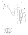
次に、第6の実施形態として、吐水設備構造をシャワーヘッド以外に適用した例について、図7〜図10を参照しながら説明する。図7(a)は、浴室Rの室内部Riから室外部Roにかけての構造を示した断面図であり、図7(b)はシャワーヘッド97の散水部94における底面部95を示した説明図である。
Next, as a sixth embodiment, an example in which the water discharge facility structure is applied to other than the shower head will be described with reference to FIGS. 7 to 10. FIG. 7A is a cross-sectional view showing the structure of the bathroom R from the indoor Ri to the outdoor Ro, and FIG. 7B is an explanatory view showing the
図7(a)に示すように、浴室Rは、室外部Roに湯水供給設備80が配置されると共に、湯水供給設備80より伸延する接続ホース81が浴室壁82を貫通し、室内部Riに配置されたシャワーヘッド97に接続されている。
As shown in FIG. 7A, in the bathroom R, the hot
本実施例は、これまで説明した実施例と比較して、シャワーヘッド97自体には本実施形態に係るシャワー構造は備えられておらず、湯水供給設備80や接続ホース81、シャワーヘッド97で構成されるシャワー設備83に本実施形態に係るシャワー構造が備えられている点で構成を異にしている。
In this embodiment, as compared with the embodiments described so far, the
具体的には、室外部Roに配設された湯水供給設備80は、図示しない給湯部より伸延する給水流路84を備えており、同給水流路84は、分流部85を経て通水流路86と電解流路87とに分岐している。
Specifically, the hot
通水流路86は接続ホース81に接続されている。一方、電解流路87は、電解槽88に接続されている。電解槽88の内部は、陰極板89a及び陽極板89bよりなる電極板89が対向配置されており、これら電極板89の間隙を通水可能としている。
The
また、電極板89はそれぞれ制御部90に電気的に接続されている。制御部90は、先端に電源プラグ91aを備えた電源ケーブル91を備えており、図示しない商用電源コンセントに接続することで、受電可能としている。
Further, each of the electrode plates 89 is electrically connected to the
制御部90は、商用電源より受電すると整流し、陰極板89a及び陽極板89bに所定の電圧を印加する。
The
電解槽88の出口側からは電解水素水送出流路92が伸延しており、同電解水素水送出流路92の下流側端部は接続ホース81に接続している。
The electrolytic hydrogen water
接続ホース81は、通水流路86から供給される非電解水11と、電解水素水送出流路92より供給される電解水素水10とが別個に流通するよう仕切部81aが形成されており、その下流側先端部にはシャワーヘッド97が螺合接続される。
The
シャワーヘッド97もまた接続ホース81と同様、把持部93から散水部94の底面部95に至るまで内部に仕切部96が形成されており、底面部95からは非電解水11と電解水素水10とがそれぞれ別個に吐出されるよう構成している。
Similar to the connecting
底面部95は、図7(b)に示すように、シャワーヘッドH1における底面部34と同様、複数の電解水素水吐出孔38が穿設された電解水素水吐出領域39と、複数の非電解水吐出孔40が穿設された非電解水吐出領域41とを備え、両領域の境界には区画領域42が形成されている。
As shown in FIG. 7B, the
そして、このような構成を備えたシャワー設備83によれば、給湯部(図示せず)より供給され、給水流路84を経て分流部85に至った湯水は、通水流路86と電解流路87とに分流される。
According to the
通水流路86に流入した湯水は、電解を受けることなく非電解水11として接続ホース81に至り、シャワーヘッド97の把持部93を経て、散水部94の底面部34の非電解水吐出領域41より非電解水吐出孔40を介して吐出される。
The hot water flowing into the
電解流路87へ流入した湯水は、対向配置された電極板89間を流れることで電解され、陰極板89aの表面にて生じた水素ガスが溶解して電解水素水10となり、電解水素水送出流路92を経て接続ホース81に至り、シャワーヘッド97の把持部93を通じて、散水部94の底面部34の電解水素水吐出領域39より電解水素水吐出孔38を介して吐出される
The hot water flowing into the
このように、上述のシャワー設備83によっても、本実施形態に係る吐水設備構造を備えているため、使用者が所望する部位へ水素水を重点的に、且つ、高濃度で浴びせることができる。
As described above, since the
次に、第7の実施形態として、吐水設備構造を打たせ湯設備に適用した例について、図8を参照しながら説明する。図8は、打たせ湯設備Uの構成を示す説明図である。 Next, as a seventh embodiment, an example in which the water discharge facility structure is applied to the hot water facility will be described with reference to FIG. FIG. 8 is an explanatory diagram showing the configuration of the hot water facility U.
打たせ湯設備Uは、壁体Wを境に施療部Uiと装置部Uoとを備えている。施療部Uiは、流下する非電解水11や電解水素水10の下に被施療者が身を置き、身体の所望する部位に水流をあてて施療を行う部位であり、壁体Wの壁面上方には切断された竹を模した筒状吐水体100が吐水部として設けられている。
The hitting hot water facility U includes a treatment unit Ui and an apparatus unit Uo with the wall body W as a boundary. The treatment unit Ui is a part where the person to be treated places himself / herself under the flowing
筒状吐水体100は、小径長尺の電解水素水吐水管100aと、大径短尺の非電解水吐水管100bとで二重管状に形成されており、各吐水管から吐出される電解水素水10と非電解水11とがその飛程において大凡混じり合わないように構成している。
The
一方、装置部Uoは、前述の浴室Rにおける室外部Roと同様、湯水供給設備80が配置されると共に、湯水供給設備80より伸延する電解水素水送出流路92及び通水流路86は、壁体Wより装置部Uo側に露出した筒状吐水体100の基部に、電解水素水吐水管100aと非電解水吐水管100bとにそれぞれ接続されている。
On the other hand, in the device unit Uo, the hot
そして、このような構成を備えた打たせ湯設備Uによれば、給湯部(図示せず)より供給され、給水流路84を経て分流部85に至った湯水は、通水流路86と電解流路87とに分流される。
Then, according to the hot water supply facility U having such a configuration, the hot water supplied from the hot water supply section (not shown) and reaches the
通水流路86に流入した湯水は、電解を受けることなく非電解水11として非電解水吐水管100bを介して吐出される。
The hot water flowing into the
一方、電解流路87へ流入した湯水は、対向配置された電極板89間を流れることで電解され、陰極板89aの表面にて生じた水素ガスが溶解して電解水素水10となり、電解水素水送出流路92を経て、電解水素水吐水管100aを介して吐出される。
On the other hand, the hot water flowing into the
このように、上述の打たせ湯設備Uによっても、本実施形態に係る吐水設備構造を備えているため、使用者が所望する部位へ水素水を重点的に、且つ、高濃度で浴びせることができる。 As described above, since the above-mentioned hot water discharge facility U also has the water discharge facility structure according to the present embodiment, it is possible to intensively spray hydrogen water on a portion desired by the user at a high concentration. it can.
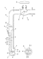
次に、第8の実施形態として、吐水設備構造を蛇口水道設備に適用した例について、図9を参照しながら説明する。図9は、蛇口水道設備J1の構成を示す説明図であって、図9(a)は蛇口水道設備J1の長手方向断面を示しており、図9(b)は通水管部102に備えられた吐水口134を示している。
Next, as an eighth embodiment, an example in which the water discharge facility structure is applied to the faucet water supply facility will be described with reference to FIG. 9A and 9B are explanatory views showing the configuration of the faucet water supply facility J1, FIG. 9A shows a longitudinal cross section of the faucet water supply facility J1, and FIG. 9B is provided in the water
蛇口水道設備J1は、所謂単水栓型の構造を備えており、水栓部101と、通水管部102とで構成している。
The faucet water supply facility J1 has a so-called single faucet type structure, and is composed of a
水栓部101は、給水流路28の通水・止水を操作する部位であり、使用者がハンドル103を回動させることにより、内部に配設されたコマ104が移動して通水・止水が行われる。
The
通水管部102は、水栓部101を介して供給される湯水を吐出部としての吐水口134に導く管であり、水栓部101に対し袋ナット105を介して接続することにより揺動可能としている。
The water
また、通水管部102は、第1実施形態にて述べたシャワーヘッドH1の内部構造と略同様の構成を備えており、電解水素水10と非電解水11とを吐水可能としている。
Further, the
具体的には、供給された湯水を区画分流する分流壁25が配設されており、その基端側端部近傍を分流部26とし、分流部26よりも上流側には、給電機構29のプロペラ29aが配設されている。
Specifically, a
また、分流壁25を隔てて通水流路31と電解流路32とを備えており、電解流路32の内周壁面には、対向状態に配設された陰極板33a及び陽極板33bよりなる一対の電極板33が配設されている。
Further, a
通水管部102の終端近傍部122は、中空に形成された吐水部として機能する部位であり、図9(b)に示すように、吐水口134を備えている。
The
また、終端近傍部122の内部には、仕切壁35を隔てて電解水素水流入空間36と非電解水流入空間37とが形成されており、電解水素水流入空間36に対応する吐水口134は、電解水素水流入空間36内に流入した電解水素水10が吐出される電解水素水吐出口138を形成して電解水素水吐出領域39とする一方、非電解水流入空間37に対応する吐水口134は、非電解水流入空間37内に流入した非電解水11が吐出される非電解水吐出口140を形成して非電解水吐出領域41としている。
Further, inside the
また、図9(b)に示すように、電解水素水吐出領域39と非電解水吐出領域41との境界には、区画手段としての区画領域42が形成されており、電解水素水吐出領域39より吐出された電解水素水10と、非電解水吐出領域41より吐出された非電解水11とが飛程において混在するのを防止している。
Further, as shown in FIG. 9B, a
そして、このような構成を備えた蛇口水道設備J1によれば、水栓部101を介して通水管部102の給水流路28を経て分流部26に至った湯水は、通水流路31と電解流路32とに分流される。
Then, according to the faucet water supply facility J1 having such a configuration, the hot water that has reached the
通水流路31に流入した湯水は、電解を受けることなく非電解水11として非電解水流入空間37へ至り、非電解水吐出領域41の非電解水吐出口140を介して吐出される。
The hot water that has flowed into the
一方、電解流路32へ流入した湯水は、対向配置された電極板33間を流れることで電解され、陰極板33aの表面にて生じた水素ガスが溶解して電解水素水10となり、電解水素水流入空間36に流入して電解水素水吐出領域39の電解水素水吐出口138を介して吐出される。
On the other hand, the hot water flowing into the
このように、上述の蛇口水道設備J1によっても、本実施形態に係る吐水設備構造を備えているため、使用者が所望する部位へ水素水を重点的に、且つ、高濃度で吐出させることができる。 As described above, since the faucet water supply facility J1 described above also has the water discharge facility structure according to the present embodiment, it is possible to discharge hydrogen water to a portion desired by the user in a focused manner and at a high concentration. it can.
次に、第9の実施形態として、吐水設備構造を蛇口水道設備に適用した更なる例について、図10を参照しながら説明する。図10は、蛇口水道設備J2の構成を示す模式説明図である。 Next, as a ninth embodiment, a further example in which the water discharge facility structure is applied to the faucet water supply facility will be described with reference to FIG. FIG. 10 is a schematic explanatory view showing the configuration of the faucet water supply facility J2.
蛇口水道設備J2は、水栓部201と、給水部202とで構成している。水栓部201は、浴室や洗面所、台所など所定の水回り領域に配設されており、使用者により操作可能としている。
The faucet water supply facility J2 is composed of a
水栓部201は、基台となるベース板203上に、第1ハンドル204、第1カラン205、第2ハンドル206、第2カラン207を配設して構成している。
The
第1ハンドル204は、給水部202より供給される非電解水11の吐水・止水を操作するためのハンドルであり、同第1ハンドル204を開操作することにより、第1カラン205から非電解水11が吐出するよう構成している。
The
第2ハンドル206は、給水部202より供給される電解水素水10の吐水・止水を操作するためのハンドルであり、同第2ハンドル206を開操作することにより、第2カラン207から電解水素水10が吐出するよう構成している。
The
第1カラン205及び第2カラン207は、それぞれ非電解水11及び電解水素水10を吐出させるためのカランであり、その基部において給水部202と通水可能に接続されている。なお、本実施形態では、第1カラン205及び第2ハンドル206自体が吐水部として機能すると共に、電解水素水と非電解水とが飛程において混在するのを防止する区画手段としても機能する。
The
給水部202は、前述の第6実施形態にて説明したシャワー設備83の湯水供給設備80と略同様の構成を備えており、給水流路84より供給された湯水を分流部85において通水流路86と電解流路87とに分岐させ、通水流路86に流入した湯水は電解することなく非電解水として第1カラン205へ導くと共に、電解流路87へ流入した湯水は電解槽88にて陰極板89aと陽極板89bとの間で電解を行って、電解水素水送出流路92を介して第2カラン207へ導く。
The
また、通水流路86の中途部及び電解水素水送出流路92の中途部には、それぞれ第1バルブ208及び第2バルブ209が介設されている。第1バルブ208及び第2バルブ209は、それぞれ第1ハンドル204及び第2ハンドル206に連動連結されており、使用者が各ハンドルを操作することで、通水流路86や電解水素水送出流路92の通水・止水が行われる。
Further, a
また、電解槽88よりも上流側となる電解流路87の中途部には、通水検知センサ210を配設している。この通水検知センサ210は、電解流路87を介して電解槽88に湯水が供給されているか否かを検知するセンサであって制御部90に対し電気的に接続されている。制御部90は、第2ハンドル206の開操作により第2バルブ209が開状態となり、第2カラン207から吐水され、電解槽88に対して電解流路87を通じて湯水が供給されている時に陰極板89a及び陽極板89bに電圧を印加して湯水の電解を行う。
Further, a water
そして、このような蛇口水道設備J2によっても、本実施形態に係る吐水設備構造を備えているため、例えば湯桶やコップなど使用者が所望する部位へ水素水を重点的に、且つ、高濃度で吐出させることができる。 Since the faucet water supply facility J2 also has the water discharge facility structure according to the present embodiment, hydrogen water is concentrated and concentrated in a portion desired by the user, such as a tub or a cup. It can be discharged.
上述してきたように、本発明に係る吐水設備構造によれば、給水流路より供給される湯水を吐水部から吐出する吐水設備の構造において、前記給水流路にて前記湯水を分流する分流部と、分流部にて分流された一方の湯水を電解して電解水素水と成し、同電解水素水を前記吐水部へ導く電解流路と、分流部にて分流された他方の湯水を電解せずに非電解水の状態で前記吐水部へ導く通水流路と、を備え、前記吐水部には、前記電解流路の下流にて電解水素水を吐出する電解水素水吐出領域と、前記通水流路の下流にて非電解水を吐出する非電解水吐出領域と、がそれぞれ別個に形成されていることとしたため、電解水素水を所望する部位へ重点的に、且つ、高濃度で吐出することのできる吐水設備構造を提供することができる。 As described above, according to the water discharge facility structure according to the present invention, in the structure of the water discharge facility that discharges the hot water supplied from the water supply flow path from the water discharge section, the diversion section that divides the hot water in the water supply flow path. Then, one hot water split at the diversion section is electrolyzed to form electrolytic hydrogen water, and the electrolytic flow path that guides the electrolytic hydrogen water to the spout section and the other hot water split at the diversion section are electrolyzed. The water discharge section is provided with a water flow path that leads to the water discharge section in the state of non-electrolyzed water, and the water discharge section has an electrolytic hydrogen water discharge region that discharges electrolytic hydrogen water downstream of the electrolytic flow path, and the water discharge section. Since the non-electrolyzed water discharge region for discharging the non-electrolyzed water downstream of the water flow path is formed separately, the electrolyzed hydrogen water is discharged to the desired portion in a concentrated manner and at a high concentration. It is possible to provide a water discharge facility structure that can be used.
最後に、上述した各実施の形態の説明は本発明の一例であり、本発明は上述の実施の形態に限定されることはない。このため、上述した各実施の形態以外であっても、本発明に係る技術的思想を逸脱しない範囲であれば、設計等に応じて種々の変更が可能であることは勿論である。 Finally, the description of each embodiment described above is an example of the present invention, and the present invention is not limited to the above-described embodiment. Therefore, it goes without saying that various changes can be made according to the design and the like as long as the technical idea of the present invention is not deviated from the above-described embodiments.
例えば、散水部22の底面部34や周面部68等の吐水面に形成される各吐水領域の配置は、適宜変更可能であることは言うまでもない。
For example, it goes without saying that the arrangement of each water discharge region formed on the water discharge surface such as the
すなわち、シャワーヘッドH1であれば、内部流路構造を適宜変更することで電解水素水吐出領域39と非電解水吐出領域41の位置を入れ替えても良いし、電解水素水10を周面部68から吐出させるようにしても良い。また、シャワーヘッドH2であれば、筒状分流壁50の内方を電解流路32として、電解水素水吐出領域39とマイクロバブル水吐出領域56との位置を入れ替えても良いし、シャワーヘッドH3であれば、アルカリ電解水素水が生成される流路と酸性水が生成される流路とを入れ替えてることもできる。
That is, in the case of the shower head H1, the positions of the electrolyzed hydrogen
また、吐水面に形成される各領域は、必ずしもそれぞれ1つずつには限定されず、電解水素水10や非電解水11が飛程において混在しないのであれば、複数設けられていても良い。
Further, each region formed on the water discharge surface is not necessarily limited to one, and a plurality of
また、シャワーヘッドH1〜H3は、起電部29cにより生成した電力により電解を行うこととしたが、これに限定されるものではなく、例えば蓄電池を備えたり、商用電源から受電して電解するよう構成しても良い。併せて、H4においても、給電機構29を備え、給水流路84にプロペラ29aを配置するなどし、外的な電力供給によらず電解可能に構成しても良いのは勿論である。
Further, the shower heads H1 to H3 are electrolyzed by the electric power generated by the
また、上述した第1〜第9の実施形態における各構成は、その機能を阻害しない範囲内において、それぞれ別の実施形態に適用することができ、これらの構成もまた本発明の概念に含まれる。 Further, each of the above-described configurations in the first to ninth embodiments can be applied to different embodiments as long as the functions are not impaired, and these configurations are also included in the concept of the present invention. ..
10 電解水素水
11 非電解水
20 吐出面
21 把持部
22 散水部
25 分流壁
26 分流部
28 給水流路
29 給電機構
29c 起電部
31 通水流路
32 電解流路
33 電極板
34 底面部
39 電解水素水吐出領域
41 非電解水吐出領域
42 区画領域
53 マイクロバブル発生部
56 マイクロバブル水吐出領域
60 区画壁
61 陰極流路
62 陽極流路
63 隔膜
67 アルカリ電解水素水吐出領域
68 周面部
70 酸性水吐出領域
81 接続ホース
83 シャワー設備
84 給水流路
85 分流部
86 通水流路
87 電解流路
94 散水部
95 底面部
H1〜H4 シャワーヘッド
U 打たせ湯設備
J1〜J2 蛇口水道設備
10
Claims (7)
前記給水流路にて前記湯水を分流する分流部と、
分流部にて分流された一方の湯水を電解して電解水素水と成し、同電解水素水を前記吐水部へ導く電解流路と、
分流部にて分流された他方の湯水を電解せずに非電解水の状態で前記吐水部へ導く通水流路と、を備え、
前記吐水部には、
前記電解流路の下流にて電解水素水を吐出する電解水素水吐出領域と、
前記通水流路の下流にて非電解水を吐出する非電解水吐出領域と、がそれぞれ別個に形成されているとともに、
前記電解水素水吐出領域に穿設された吐出孔と、前記非電解水吐出領域に穿設された吐出孔は、相互に離隔する方向へ吐出する角度で穿設されていることを特徴とする吐水設備構造。 In the structure of the water discharge facility that discharges hot water supplied from the water supply channel from the water discharge section
A diversion section that diverts the hot water in the water supply flow path,
An electrolytic flow path that electrolyzes one of the hot water separated at the diversion section to form electrolytic hydrogen water and guides the electrolytic hydrogen water to the spouting section.
It is provided with a water flow path that guides the other hot water separated at the diversion section to the spouting section in the state of non-electrolyzed water without electrolyzing.
In the water discharge part
An electrolytic hydrogen water discharge region for discharging electrolytic hydrogen water downstream of the electrolytic flow path,
A non-electrolyzed water discharge region for discharging non-electrolyzed water downstream of the water flow path is formed separately, and is also formed separately .
The discharge hole bored in the electrolytic hydrogen water discharge region and the discharge hole bored in the non-electrolyzed water discharge region are bored at an angle of discharging in a direction away from each other. Water discharge facility structure.
前記給水流路にて前記湯水を分流する分流部と、
分流部にて分流された一方の湯水を電解して電解水素水と成し、同電解水素水を前記吐水部へ導く電解流路と、
分流部にて分流された他方の湯水を電解せずに非電解水の状態で前記吐水部へ導く通水流路と、を備え、
前記吐水部には、
前記電解流路の下流にて電解水素水を吐出する電解水素水吐出領域と、
前記通水流路の下流にて非電解水を吐出する非電解水吐出領域と、がそれぞれ別個に形成されているとともに、
前記電解流路は、アルカリ性の電解水素水を生成する陰極が配置された陰極流路と、酸性水を生成する陽極が配置された陽極流路とを備え、両流路は相互の流通を規制する区画壁にて仕切られており、
前記電解水素水吐出領域には、アルカリ電解水素水を吐出するアルカリ電解水素水吐出領域と、酸性水を吐出する酸性水吐出領域とが、それぞれ別個に形成されていることを特徴とする請求項1に記載の吐水設備構造。 In the structure of the water discharge facility that discharges hot water supplied from the water supply channel from the water discharge section
A diversion section that diverts the hot water in the water supply flow path,
An electrolytic flow path that electrolyzes one of the hot water separated at the diversion section to form electrolytic hydrogen water and guides the electrolytic hydrogen water to the spouting section.
It is provided with a water flow path that guides the other hot water separated at the diversion section to the spouting section in the state of non-electrolyzed water without electrolyzing.
In the water discharge part
An electrolytic hydrogen water discharge region for discharging electrolytic hydrogen water downstream of the electrolytic flow path,
A non-electrolyzed water discharge region for discharging non-electrolyzed water downstream of the water flow path is formed separately, and is also formed separately.
The electrolytic flow path includes a cathode flow path in which a cathode for generating alkaline electrolytic hydrogen water is arranged and an anode flow path in which an anode for generating acidic water is arranged, and both flow paths regulate mutual flow. It is separated by a partition wall
The claim is characterized in that, in the electrolytic hydrogen water discharge region, an alkaline electrolytic hydrogen water discharge region for discharging alkaline electrolytic hydrogen water and an acidic water discharge region for discharging acidic water are separately formed. The water discharge facility structure according to 1.
Priority Applications (2)
| Application Number | Priority Date | Filing Date | Title |
|---|---|---|---|
| JP2016112898A JP6768356B2 (en) | 2016-06-06 | 2016-06-06 | Shower head, faucet water supply equipment, hot water supply equipment with water discharge equipment structure and the same water discharge equipment structure |
| PCT/JP2017/015980 WO2017212802A1 (en) | 2016-06-06 | 2017-04-21 | Water discharge facility structure, shower head provided with water discharge facility structure, faucet water supply facility, waterfall bath facility |
Applications Claiming Priority (1)
| Application Number | Priority Date | Filing Date | Title |
|---|---|---|---|
| JP2016112898A JP6768356B2 (en) | 2016-06-06 | 2016-06-06 | Shower head, faucet water supply equipment, hot water supply equipment with water discharge equipment structure and the same water discharge equipment structure |
Publications (2)
| Publication Number | Publication Date |
|---|---|
| JP2017217158A JP2017217158A (en) | 2017-12-14 |
| JP6768356B2 true JP6768356B2 (en) | 2020-10-14 |
Family
ID=60577784
Family Applications (1)
| Application Number | Title | Priority Date | Filing Date |
|---|---|---|---|
| JP2016112898A Active JP6768356B2 (en) | 2016-06-06 | 2016-06-06 | Shower head, faucet water supply equipment, hot water supply equipment with water discharge equipment structure and the same water discharge equipment structure |
Country Status (2)
| Country | Link |
|---|---|
| JP (1) | JP6768356B2 (en) |
| WO (1) | WO2017212802A1 (en) |
Cited By (1)
| Publication number | Priority date | Publication date | Assignee | Title |
|---|---|---|---|---|
| KR20240040862A (en) * | 2022-09-22 | 2024-03-29 | 주식회사 뉴워터텍 | Shower head using self-generation, electrolysis and micro-bubble with antibacterial and pore cleaning function |
Families Citing this family (10)
| Publication number | Priority date | Publication date | Assignee | Title |
|---|---|---|---|---|
| CN107890958B (en) * | 2017-12-18 | 2023-08-01 | 厦门松霖科技股份有限公司 | Micro-electrotherapy beauty shower and micro-electrotherapy method |
| US11154878B2 (en) | 2017-12-18 | 2021-10-26 | Xiamen Solex High-Tech Industries Co., Ltd. | Micro-current therapy beauty care shower head and micro-current therapy |
| JP7082903B2 (en) * | 2018-05-14 | 2022-06-09 | マクセル株式会社 | shower head |
| JP7199962B2 (en) * | 2018-12-26 | 2023-01-06 | マクセル株式会社 | shower head |
| CN109620697B (en) * | 2019-01-08 | 2021-10-26 | 郝凤兰 | Clinical medicine feeding device of gynaecology and obstetrics |
| CN109817276B (en) * | 2019-01-29 | 2023-05-23 | 鲁东大学 | A Method for Protein Secondary Structure Prediction Based on Deep Neural Network |
| JP7130570B2 (en) * | 2019-02-05 | 2022-09-05 | マクセル株式会社 | shower head |
| CN109967275A (en) * | 2019-04-29 | 2019-07-05 | 绍兴上虞优耐德管业有限公司 | A kind of shower head |
| JP7335145B2 (en) * | 2019-11-26 | 2023-08-29 | 株式会社 資生堂 | SKIN CLEANING DEVICE AND SKIN CLEANING METHOD |
| JP7181966B1 (en) * | 2021-05-13 | 2022-12-01 | 株式会社日本トリム | Electrolyzer and water supply system |
Family Cites Families (6)
| Publication number | Priority date | Publication date | Assignee | Title |
|---|---|---|---|---|
| JP2001169952A (en) * | 1999-12-15 | 2001-06-26 | Toto Ltd | Shower equipment |
| JP2002004368A (en) * | 2000-06-21 | 2002-01-09 | Kvk Corp | shower head |
| US20090314851A1 (en) * | 2006-03-10 | 2009-12-24 | Michael Bonacci | Dual hose showerhead |
| JP2008229516A (en) * | 2007-03-20 | 2008-10-02 | Univ Of Tsukuba | Micro bubble shower |
| JP2014210002A (en) * | 2013-04-18 | 2014-11-13 | 義久 林 | Mist generator and showerhead to be used for the same |
| JP2015098014A (en) * | 2013-10-18 | 2015-05-28 | 株式会社熊本アイディーエム | Electrolytic water micro nano-bubble generator |
-
2016
- 2016-06-06 JP JP2016112898A patent/JP6768356B2/en active Active
-
2017
- 2017-04-21 WO PCT/JP2017/015980 patent/WO2017212802A1/en not_active Ceased
Cited By (2)
| Publication number | Priority date | Publication date | Assignee | Title |
|---|---|---|---|---|
| KR20240040862A (en) * | 2022-09-22 | 2024-03-29 | 주식회사 뉴워터텍 | Shower head using self-generation, electrolysis and micro-bubble with antibacterial and pore cleaning function |
| KR102822123B1 (en) * | 2022-09-22 | 2025-06-23 | 주식회사 뉴워터텍 | Shower head using self-generation, electrolysis and micro-bubble with antibacterial and pore cleaning function |
Also Published As
| Publication number | Publication date |
|---|---|
| WO2017212802A1 (en) | 2017-12-14 |
| JP2017217158A (en) | 2017-12-14 |
Similar Documents
| Publication | Publication Date | Title |
|---|---|---|
| JP6768356B2 (en) | Shower head, faucet water supply equipment, hot water supply equipment with water discharge equipment structure and the same water discharge equipment structure | |
| KR101826750B1 (en) | Vibrating Shower Device Having a Function Of LED Display | |
| KR101608475B1 (en) | apparatus for manufacturing hydrogen water of high density | |
| CN107585846B (en) | Hydrogen shower water system | |
| CN111389610A (en) | Liquid spraying device | |
| KR20080092750A (en) | Oxygen Microbubble Feeder | |
| KR20190027103A (en) | water rap shower | |
| JP6502098B2 (en) | Beauty equipment | |
| CN104048075B (en) | Tap | |
| KR102376857B1 (en) | Fine bubble generator and functional shower head using the generator | |
| JP4807967B2 (en) | Bathing equipment | |
| JP2011152485A (en) | Charged particulate water-containing fine bubble generator | |
| KR20150118215A (en) | Bidet including Nozzle Assembly | |
| JP6624672B2 (en) | Ultra-fine bubble generator for bathroom | |
| JP3244651U (en) | head spa equipment | |
| JP2009011521A (en) | Oxygen-enriched mist generator | |
| CN216631244U (en) | Micro-nano bubble goes out water equipment | |
| JP6554244B1 (en) | Hydrogen gas charging device provided side by side with pool type water tank, pool type water tank equipped with hydrogen gas charging device and hydrogen gas charging method to pool type water tank | |
| CN202516716U (en) | Sprayer | |
| JP2019013482A (en) | Bathtub circulation type water discharge device | |
| CN106176182A (en) | A kind of hydrotherapy apparatus of the super oxygen-enriched energy of sound wave | |
| JP2006334385A (en) | Facial care equipment | |
| WO2012147459A1 (en) | Multipurpose gas dissolution device | |
| KR20210117978A (en) | Shower | |
| CN203803668U (en) | Multifunctional eddy jet water-saving sprinkler |
Legal Events
| Date | Code | Title | Description |
|---|---|---|---|
| A621 | Written request for application examination |
Free format text: JAPANESE INTERMEDIATE CODE: A621 Effective date: 20190327 |
|
| A131 | Notification of reasons for refusal |
Free format text: JAPANESE INTERMEDIATE CODE: A131 Effective date: 20200407 |
|
| A521 | Request for written amendment filed |
Free format text: JAPANESE INTERMEDIATE CODE: A523 Effective date: 20200518 |
|
| TRDD | Decision of grant or rejection written | ||
| A01 | Written decision to grant a patent or to grant a registration (utility model) |
Free format text: JAPANESE INTERMEDIATE CODE: A01 Effective date: 20200901 |
|
| A61 | First payment of annual fees (during grant procedure) |
Free format text: JAPANESE INTERMEDIATE CODE: A61 Effective date: 20200923 |
|
| R150 | Certificate of patent or registration of utility model |
Ref document number: 6768356 Country of ref document: JP Free format text: JAPANESE INTERMEDIATE CODE: R150 |
|
| S533 | Written request for registration of change of name |
Free format text: JAPANESE INTERMEDIATE CODE: R313533 |
|
| R350 | Written notification of registration of transfer |
Free format text: JAPANESE INTERMEDIATE CODE: R350 |
|
| R250 | Receipt of annual fees |
Free format text: JAPANESE INTERMEDIATE CODE: R250 |
|
| R250 | Receipt of annual fees |
Free format text: JAPANESE INTERMEDIATE CODE: R250 |
|
| R250 | Receipt of annual fees |
Free format text: JAPANESE INTERMEDIATE CODE: R250 |