JP6776357B2 - 液体を充填すべきボトルおよび充填用モジュールを含む充填用システム - Google Patents
液体を充填すべきボトルおよび充填用モジュールを含む充填用システム Download PDFInfo
- Publication number
- JP6776357B2 JP6776357B2 JP2018536339A JP2018536339A JP6776357B2 JP 6776357 B2 JP6776357 B2 JP 6776357B2 JP 2018536339 A JP2018536339 A JP 2018536339A JP 2018536339 A JP2018536339 A JP 2018536339A JP 6776357 B2 JP6776357 B2 JP 6776357B2
- Authority
- JP
- Japan
- Prior art keywords
- valve
- pipe
- plate
- bottle
- filling
- Prior art date
- Legal status (The legal status is an assumption and is not a legal conclusion. Google has not performed a legal analysis and makes no representation as to the accuracy of the status listed.)
- Active
Links
Images








Classifications
-
- B—PERFORMING OPERATIONS; TRANSPORTING
- B05—SPRAYING OR ATOMISING IN GENERAL; APPLYING FLUENT MATERIALS TO SURFACES, IN GENERAL
- B05B—SPRAYING APPARATUS; ATOMISING APPARATUS; NOZZLES
- B05B11/00—Single-unit hand-held apparatus in which flow of contents is produced by the muscular force of the operator at the moment of use
- B05B11/0005—Components or details
- B05B11/0037—Containers
- B05B11/0056—Containers with an additional opening for filling or refilling
-
- A—HUMAN NECESSITIES
- A45—HAND OR TRAVELLING ARTICLES
- A45D—HAIRDRESSING OR SHAVING EQUIPMENT; EQUIPMENT FOR COSMETICS OR COSMETIC TREATMENTS, e.g. FOR MANICURING OR PEDICURING
- A45D34/00—Containers or accessories specially adapted for handling liquid toiletry or cosmetic substances, e.g. perfumes
- A45D34/02—Scent flasks, e.g. with evaporator
-
- B—PERFORMING OPERATIONS; TRANSPORTING
- B05—SPRAYING OR ATOMISING IN GENERAL; APPLYING FLUENT MATERIALS TO SURFACES, IN GENERAL
- B05B—SPRAYING APPARATUS; ATOMISING APPARATUS; NOZZLES
- B05B11/00—Single-unit hand-held apparatus in which flow of contents is produced by the muscular force of the operator at the moment of use
- B05B11/0005—Components or details
- B05B11/0037—Containers
- B05B11/0039—Containers associated with means for compensating the pressure difference between the ambient pressure and the pressure inside the container, e.g. pressure relief means
- B05B11/0044—Containers associated with means for compensating the pressure difference between the ambient pressure and the pressure inside the container, e.g. pressure relief means compensating underpressure by ingress of atmospheric air into the container, i.e. with venting means
-
- B—PERFORMING OPERATIONS; TRANSPORTING
- B05—SPRAYING OR ATOMISING IN GENERAL; APPLYING FLUENT MATERIALS TO SURFACES, IN GENERAL
- B05B—SPRAYING APPARATUS; ATOMISING APPARATUS; NOZZLES
- B05B11/00—Single-unit hand-held apparatus in which flow of contents is produced by the muscular force of the operator at the moment of use
- B05B11/01—Single-unit hand-held apparatus in which flow of contents is produced by the muscular force of the operator at the moment of use characterised by the means producing the flow
- B05B11/10—Pump arrangements for transferring the contents from the container to a pump chamber by a sucking effect and forcing the contents out through the dispensing nozzle
- B05B11/1001—Piston pumps
-
- B—PERFORMING OPERATIONS; TRANSPORTING
- B67—OPENING, CLOSING OR CLEANING BOTTLES, JARS OR SIMILAR CONTAINERS; LIQUID HANDLING
- B67D—DISPENSING, DELIVERING OR TRANSFERRING LIQUIDS, NOT OTHERWISE PROVIDED FOR
- B67D7/00—Apparatus or devices for transferring liquids from bulk storage containers or reservoirs into vehicles or into portable containers, e.g. for retail sale purposes
- B67D7/02—Apparatus or devices for transferring liquids from bulk storage containers or reservoirs into vehicles or into portable containers, e.g. for retail sale purposes for transferring liquids other than fuel or lubricants
- B67D7/0288—Container connection means
- B67D7/0294—Combined with valves
Landscapes
- Basic Packing Technique (AREA)
- Filling Of Jars Or Cans And Processes For Cleaning And Sealing Jars (AREA)
- Coating Apparatus (AREA)
- Containers And Packaging Bodies Having A Special Means To Remove Contents (AREA)
Description
−2つの孔があいたベースを伴う中空ケーシングを有するボトルと、
−充填用モジュールであって、
−底面を有するタンク、
−高位置と低位置との間で垂直方向に並進運動し、ベースを収容するための場所を有するプレート、
−柔軟なケーシングの形をしたポンプ、
−プレートが高位置から低位置まで移行した場合にポンプを圧縮するように構成された圧縮システム、
−プレートを高位置に強制する復元手段、および
−一方ではタンクとプレートとの間、他方ではタンクとポンプとの間のパイプセット、
を含む充填用モジュールと、
−プレートとベースとの間の流体用連結アセンブリであって、
−各孔について、前記孔の中に収納され、パイプによりボトル内に延長され、閉鎖位置と開放位置との間で可動であるバルブ、
−プレート上に固定され、閉鎖位置と開放位置との間で可動である第1のバルブおよび第2のバルブであって、第1のバルブが一方のバルブと協働するように想定され、第2のバルブがもう一方のバルブと協働するように想定されており、第2のバルブが前記パイプセットの1つのパイプに連結されている、第1および第2のバルブ、
を含むプレートとベースとの間の流体用連結アセンブリと、
を含む充填用システムにおいて、
前記パイプセットが、
−底面のレベルでタンク内に通じている第1のパイプと、
−底面から離れたところからタンク内に通じ、第2のバルブに連結された第2のパイプと、
−第1のパイプの液体をポンプに向かって通過させる、第1のパイプとポンプとの間の第1のチェックバルブと、
−第1のバルブを延長する接続用パイプと、
−ポンプの液体を接続用パイプに向かって通過させる、接続用パイプとポンプとの間の第2のチェックバルブと、
−第1のバルブが一方のバルブと接触状態にあり第2のバルブがもう一方のバルブと接触状態にある場合に、バルブを同時に開放し、バルブが接触状態にない場合にはこれらのバルブを同時に閉鎖するように構成されている、開閉機構と、
を含み、
充填用モジュールは、互いに固定され間には第2のパイプの一部分がくり抜き部によって実現されているベースプレートとサブベースプレートで構成されたベースを含んでおり、プレートは、互いに固定され間には第2のパイプの一部分がくり抜き部によって実現されているオーバープレートとサブプレートで構成されており、第2のパイプは、プレートとベースとの間に延在する中間部分を有し、中間部分は、ベローズ管の形をとっている、
充填用システムが提案される。
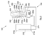
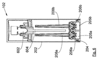
−ベース204を伴うケーシング202を有するボトル102、
−充填用モジュール104であって、
−タンク210a〜b、
−高位置と低位置との間で垂直方向に並進運動252し、ベース204を収容するための場所を有するプレート256、
−柔軟なケーシングの形をしたポンプ220、
−プレート256が高位置から低位置まで移行した場合にポンプ220を圧縮するように構成された圧縮システム250、
−プレート256を高位置に強制する復元手段254、
−一方ではタンク210a〜bとプレート256との間、他方ではタンク210a〜bとポンプ220との間のパイプセット214、216、224、
を含む充填用モジュール、
−プレート256とベース204との間の流体用連結アセンブリ218a〜b、206a〜b。
−各孔205a〜bについて、前記孔205a〜bの中に収納されたバルブ206a〜b、
−前記パイプセットのうちの1つのパイプ216に連結された第1のバルブ218aおよび第2のバルブ218b。
−第1のパイプ214、
−第2のバルブ218bに連結された第2のパイプ216、
−第1のチェックバルブ222a、
−接続用パイプ224、
−第2のチェックバルブ222b、および
−開閉機構。
−第1の側面1214aの上端部と第2の先端部1216の上部部分との間の接合部のレベルに位置する第1の下降段1218a(位置C)、
−第2の先端部1216の底部の直ぐ上流側に位置する第2の下降段1218b(位置D)、および
−第2の側面1214bの上端部と第2の先端部1216の上部部分との間の接合部レベルに位置する第3の下降段1218c(位置E)。
102 ボトル
104 充填用モジュール
202 中空ケーシング
204 ベース
205a、b 孔
206a、b バルブ
208a、b パイプ
210a、b タンク
212a、b 底面
214 第1のパイプ
216 第2のパイプ
218a 第1のバルブ
218b 第2のバルブ
220 ポンプ
222a 第1のチェックバルブ
222b 第2のチェックバルブ
224 接続用パイプ
250 圧縮システム
254 復元手段
256 プレート
Claims (8)
- −2つの孔(205a〜b)があいたベース(204)を伴う中空ケーシング(202)を有するボトル(102)と、
−充填用モジュール(104)であって、
−底面(212a〜b)を有するタンク(210a〜b)、
−高位置と低位置との間で垂直方向に並進運動(252)しベース(204)を収容するための場所を有するプレート(256)、
−柔軟なケーシングの形をしたポンプ(220)、
−プレート(256)が高位置から低位置まで移行した場合にポンプ(220)を圧縮するように構成された圧縮システム(250)、
−プレート(256)を高位置に強制する復元手段(254)、および
−一方ではタンク(210a〜b)とプレート(256)との間、他方ではタンク(210a〜b)とポンプ(220)との間のパイプセット(214、216、224)、
を含む充填用モジュールと、
−プレート(256)とベース(204)との間の流体用連結アセンブリ(218a〜b、206a〜b)であって、
−各孔(205a〜b)について、前記孔(205a〜b)の中に収納され、パイプ(208a〜b)によりボトル(102)内に延長され、閉鎖位置と開放位置との間で可動であるバルブ(206a〜b)、
−プレート(256)上に固定され、閉鎖位置と開放位置との間で可動である第1のバルブ(218a)および第2のバルブ(218b)であって、第1のバルブ(218a)が一方のバルブ(206a)と協働するように想定され、第2のバルブ(218b)がもう一方のバルブ(206b)と協働するように想定されており、第2のバルブ(218b)が前記パイプセット(214、216、224)の1つのパイプ(216)に連結されている、第1および第2のバルブ、
を含むプレートとベースとの間の流体用連結アセンブリと、
を含む充填用システム(100)において、
前記パイプセット(214、216、224)が、
−底面(212a)のレベルでタンク(210a)内に通じている第1のパイプ(214)と、
−底面(212a)から離れたところからタンク(210a)内に通じ、第2のバルブ(218b)に連結された第2のパイプ(216)と、
−第1のパイプ(214)の液体をポンプ(220)に向かって通過させる、第1のパイプ(214)とポンプ(220)との間の第1のチェックバルブ(222a)と、
−第1のバルブ(218a)を延長する接続用パイプ(224)と、
−ポンプ(220)の液体を接続用パイプ(224)に向かって通過させる、接続用パイプ(224)とポンプ(220)との間の第2のチェックバルブ(222b)と、
−第1のバルブ(218a)が一方のバルブ(206a)と接触状態にあり第2のバルブ(218b)がもう一方のバルブ(206b)と接触状態にある場合に、バルブ(205a〜b、2018a〜b)を同時に開放し、バルブ(205a〜b、218a〜b)が接触状態にない場合にはこれらのバルブを同時に閉鎖するように構成されている、開閉機構と、
を含み、
充填用モジュール(104)は、互いに固定され間には第2のパイプ(216)の一部分がくり抜き部によって実現されているベースプレート(706)とサブベースプレート(708)で構成されたベース(704)を含んでおり、プレート(256)は、互いに固定され間には第2のパイプ(216)の一部分がくり抜き部によって実現されているオーバープレート(956a)とサブプレート(956b)で構成されており、第2のパイプ(216)は、プレート(256)とベース(704)との間に延在する中間部分(916)を有し、中間部分(916)は、ベローズ管の形をとっている、
充填用システム(100)。 - ボトル(102)内に通じる2つのパイプ(208a〜b)の端部がボトル(102)内で同じ高さにあることを特徴とする、請求項1に記載の充填用システム(100)。
- 第1のパイプ(214)が底面(212a)に対して同じ高さになる形でタンク(210a)内に通じていることを特徴とする、請求項1に記載の充填用システム(100)。
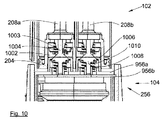
- ボトル(102)の各バルブ(205a〜b)が1つの弁座(1002)および1つの弁体(1003)を有すること、弁座(1002)がバネ(1004)上に組付けられており、下降位置と上昇位置との間で垂直方向に可動であること、弁体(1003)が固定であり、プレート(256)の方に方向づけられた裾広がり部分を有すること、第1のバルブ(218a)および第2のバルブ(218b)が各々1つの弁座(1006)と1つの弁体(1008)を有すること、弁体(1008)が、ボトル(102)の方に方向づけられた裾広がり部分を有すること、弁体(1008)がバネ(1010)上に組付けられ、上昇位置と下降位置との間で垂直方向に可動であること、および弁座(1006)が固定であることを特徴とする、請求項1に記載の充填用システム(100)。
- 復元手段(254)がポンプ(220)内に収納された圧縮バネからなることを特徴とする、請求項1に記載の充填用システム(100)。
- 充填用モジュール(104)は、第1および第2のバルブ(218a〜b)の上方に窓(714)があけられたハウジング(702)、ハウジング(702)上に組付けられ、仕切り板(716)が窓(714)をふさぐ閉鎖位置と仕切り板(716)が窓(714)をふさいでいない開放位置との間で可動である仕切り板(716)、および仕切り板(716)を閉鎖位置に強制する復元手段(720)を有していることを特徴とする、請求項1に記載の充填用システム(100)。
- プレート(256)が少なくとも1つのマグネット(960)を有すること、およびボトル(102)のベース(204)がマグネットまたは各マグネット(960)について1つずつの逆の極性を有する反対のマグネットを有することを特徴とする、請求項1に記載の充填用システム(100)。
- 充填用モジュール(104)が、低位置でプレート(256)を阻止する阻止位置またはプレート(256)が高位置に到達できる解放位置を交互にとることのできる阻止用システム(1200)を有することを特徴とする、請求項1に記載の充填用システム(100)。
Applications Claiming Priority (3)
| Application Number | Priority Date | Filing Date | Title |
|---|---|---|---|
| FR1559442 | 2015-10-05 | ||
| FR1559442A FR3041943B1 (fr) | 2015-10-05 | 2015-10-05 | Systeme de remplissage comportant un flacon a remplir avec un liquide et un module de remplissage |
| PCT/EP2016/073477 WO2017060174A1 (fr) | 2015-10-05 | 2016-09-30 | Système de remplissage comportant un flacon à remplir avec un liquide et un module de remplissage |
Publications (2)
| Publication Number | Publication Date |
|---|---|
| JP2018532663A JP2018532663A (ja) | 2018-11-08 |
| JP6776357B2 true JP6776357B2 (ja) | 2020-10-28 |
Family
ID=54707999
Family Applications (1)
| Application Number | Title | Priority Date | Filing Date |
|---|---|---|---|
| JP2018536339A Active JP6776357B2 (ja) | 2015-10-05 | 2016-09-30 | 液体を充填すべきボトルおよび充填用モジュールを含む充填用システム |
Country Status (8)
| Country | Link |
|---|---|
| US (1) | US10894264B2 (ja) |
| EP (1) | EP3359299B1 (ja) |
| JP (1) | JP6776357B2 (ja) |
| KR (1) | KR102562399B1 (ja) |
| CN (1) | CN108348938B (ja) |
| ES (1) | ES2774479T3 (ja) |
| FR (1) | FR3041943B1 (ja) |
| WO (1) | WO2017060174A1 (ja) |
Families Citing this family (2)
| Publication number | Priority date | Publication date | Assignee | Title |
|---|---|---|---|---|
| WO2021093972A1 (de) * | 2019-11-15 | 2021-05-20 | ADA Cosmetics International GmbH | Pumpspender, füllvorichtung und nachfüllsystem mit einer mehrzahl von pumspendern |
| IT202200023457A1 (it) | 2022-11-15 | 2024-05-15 | La Bottega S P A | Dispositivo erogatore di liquido ricaricabile. |
Family Cites Families (12)
| Publication number | Priority date | Publication date | Assignee | Title |
|---|---|---|---|---|
| JPH0654579U (ja) * | 1992-12-28 | 1994-07-26 | 株式会社三谷バルブ | 携帯用吐出容器 |
| JPH09301301A (ja) * | 1996-05-15 | 1997-11-25 | Sanken Electric Co Ltd | 細管部分を有する容器に対する流動体充填装置 |
| FR2802447B1 (fr) * | 1999-12-16 | 2002-02-15 | Lir France Sa | Systeme vaporisateur rechargeable |
| EP1615823A1 (fr) * | 2003-04-16 | 2006-01-18 | Gotec SA | Dispositif de remplissage d'un liquide dans un contenant |
| DE102008027987A1 (de) * | 2008-03-04 | 2009-09-17 | Kist-Europe Forschungsgesellschaft Mbh | Dosierungsvorrichtung |
| CN201329329Y (zh) | 2008-12-26 | 2009-10-21 | 东莞怡信磁碟有限公司 | 改进型便携可充式喷液瓶 |
| FR2949764B1 (fr) * | 2009-09-07 | 2011-11-25 | Maitrise & Innovation | Dispositif de distribution a diffuseur mobile et embase fixe comportant une pompe electrique miniature |
| FR2966129B1 (fr) | 2010-10-18 | 2012-10-19 | Rexam Dispensing Sys | Procede et flacon de distribution d'un produit fluide |
| FR2974074B1 (fr) * | 2011-04-14 | 2014-07-04 | Valois Sas | Systeme de recharge de produit fluide. |
| FR2978134B1 (fr) * | 2011-07-21 | 2014-04-25 | Valois Sas | Systeme de remplissage de distributeur nomade. |
| CN202321216U (zh) * | 2011-12-14 | 2012-07-11 | 东莞怡信磁碟有限公司 | 一种可充式喷液瓶 |
| FR2996828B1 (fr) * | 2012-10-15 | 2014-10-24 | Rexam Dispensing Sys | Flacon remplissable de distribution d’un produit fluide |
-
2015
- 2015-10-05 FR FR1559442A patent/FR3041943B1/fr not_active Expired - Fee Related
-
2016
- 2016-09-30 ES ES16778289T patent/ES2774479T3/es active Active
- 2016-09-30 US US15/758,784 patent/US10894264B2/en active Active
- 2016-09-30 KR KR1020187012911A patent/KR102562399B1/ko active Active
- 2016-09-30 EP EP16778289.5A patent/EP3359299B1/fr active Active
- 2016-09-30 JP JP2018536339A patent/JP6776357B2/ja active Active
- 2016-09-30 WO PCT/EP2016/073477 patent/WO2017060174A1/fr not_active Ceased
- 2016-09-30 CN CN201680056253.8A patent/CN108348938B/zh not_active Expired - Fee Related
Also Published As
| Publication number | Publication date |
|---|---|
| US20190047003A1 (en) | 2019-02-14 |
| WO2017060174A1 (fr) | 2017-04-13 |
| JP2018532663A (ja) | 2018-11-08 |
| EP3359299A1 (fr) | 2018-08-15 |
| ES2774479T3 (es) | 2020-07-21 |
| EP3359299B1 (fr) | 2019-12-04 |
| KR20180092937A (ko) | 2018-08-20 |
| KR102562399B1 (ko) | 2023-08-01 |
| FR3041943A1 (fr) | 2017-04-07 |
| FR3041943B1 (fr) | 2019-04-19 |
| US10894264B2 (en) | 2021-01-19 |
| CN108348938B (zh) | 2020-11-06 |
| CN108348938A (zh) | 2018-07-31 |
Similar Documents
| Publication | Publication Date | Title |
|---|---|---|
| TW201429859A (zh) | 水平泵、再塡充單元、及具有整合空氣壓縮器之泡沫施配器 | |
| CN102448355B (zh) | 泵装置和用于制造该泵装置的方法 | |
| CN105209347B (zh) | 具有侧边按钮的抽吸式化妆品容器 | |
| KR101219011B1 (ko) | 디스펜서 펌프버튼 | |
| US20170082475A1 (en) | Fixed quantity discharge device for liquid container | |
| US20160058154A1 (en) | Fixed Quantity Discharge Device for Liquid Container | |
| CN104884174B (zh) | 泡沫分配器 | |
| US20170291185A1 (en) | Dispenser Container | |
| TW201350071A (zh) | 液體分配器泵 | |
| CN103384789B (zh) | 用于流体分配器的阀组件 | |
| CN101289126A (zh) | 定量吐出内容物的喷嘴头下降型真空密封泵分配器 | |
| KR20190142046A (ko) | 펌프식 액체 밀폐용기 | |
| JP6776357B2 (ja) | 液体を充填すべきボトルおよび充填用モジュールを含む充填用システム | |
| KR200467835Y1 (ko) | 거품 발생 펌프 | |
| KR102499504B1 (ko) | 기밀 방식으로 폐쇄된 보틀을 위한 충전 장치 | |
| JP2002066401A (ja) | 流動体吐出ポンプ | |
| KR101383919B1 (ko) | 이종유체 토출형 화장품 용기 | |
| KR101987601B1 (ko) | 펌프식 액체 밀폐용기 | |
| KR20080015392A (ko) | 용기로부터 유체를 분배하는 도우징 헤드 | |
| JP2019018917A (ja) | ポンプ式液体密閉容器 | |
| KR101649099B1 (ko) | 크림타입 화장품용기 | |
| KR101038011B1 (ko) | 액체 저장용기의 펌프 | |
| KR20150114492A (ko) | 유체 디스펜싱 디바이스 및 이러한 디바이스의 생산 방법 | |
| KR100835312B1 (ko) | 가습기 및 가습기용 보충수 물통 | |
| US20200009780A1 (en) | Inverted cylinder assembly for forming and filling a container with liquid |
Legal Events
| Date | Code | Title | Description |
|---|---|---|---|
| A521 | Request for written amendment filed |
Free format text: JAPANESE INTERMEDIATE CODE: A523 Effective date: 20180727 |
|
| RD01 | Notification of change of attorney |
Free format text: JAPANESE INTERMEDIATE CODE: A7426 Effective date: 20190207 |
|
| A521 | Request for written amendment filed |
Free format text: JAPANESE INTERMEDIATE CODE: A821 Effective date: 20190207 |
|
| A521 | Request for written amendment filed |
Free format text: JAPANESE INTERMEDIATE CODE: A523 Effective date: 20190813 |
|
| A621 | Written request for application examination |
Free format text: JAPANESE INTERMEDIATE CODE: A621 Effective date: 20190823 |
|
| A521 | Request for written amendment filed |
Free format text: JAPANESE INTERMEDIATE CODE: A821 Effective date: 20190813 |
|
| A977 | Report on retrieval |
Free format text: JAPANESE INTERMEDIATE CODE: A971007 Effective date: 20200826 |
|
| TRDD | Decision of grant or rejection written | ||
| A01 | Written decision to grant a patent or to grant a registration (utility model) |
Free format text: JAPANESE INTERMEDIATE CODE: A01 Effective date: 20200908 |
|
| A61 | First payment of annual fees (during grant procedure) |
Free format text: JAPANESE INTERMEDIATE CODE: A61 Effective date: 20201007 |
|
| R150 | Certificate of patent or registration of utility model |
Ref document number: 6776357 Country of ref document: JP Free format text: JAPANESE INTERMEDIATE CODE: R150 |
|
| R250 | Receipt of annual fees |
Free format text: JAPANESE INTERMEDIATE CODE: R250 |
|
| R250 | Receipt of annual fees |
Free format text: JAPANESE INTERMEDIATE CODE: R250 |
|
| R250 | Receipt of annual fees |
Free format text: JAPANESE INTERMEDIATE CODE: R250 |