JP6800959B2 - カムシャフト調整器 - Google Patents
カムシャフト調整器 Download PDFInfo
- Publication number
- JP6800959B2 JP6800959B2 JP2018512528A JP2018512528A JP6800959B2 JP 6800959 B2 JP6800959 B2 JP 6800959B2 JP 2018512528 A JP2018512528 A JP 2018512528A JP 2018512528 A JP2018512528 A JP 2018512528A JP 6800959 B2 JP6800959 B2 JP 6800959B2
- Authority
- JP
- Japan
- Prior art keywords
- housing
- shaft
- actuating
- output element
- plain bearing
- Prior art date
- Legal status (The legal status is an assumption and is not a legal conclusion. Google has not performed a legal analysis and makes no representation as to the accuracy of the status listed.)
- Active
Links
Images



Classifications
-
- F—MECHANICAL ENGINEERING; LIGHTING; HEATING; WEAPONS; BLASTING
- F01—MACHINES OR ENGINES IN GENERAL; ENGINE PLANTS IN GENERAL; STEAM ENGINES
- F01L—CYCLICALLY OPERATING VALVES FOR MACHINES OR ENGINES
- F01L1/00—Valve-gear or valve arrangements, e.g. lift-valve gear
- F01L1/34—Valve-gear or valve arrangements, e.g. lift-valve gear characterised by the provision of means for changing the timing of the valves without changing the duration of opening and without affecting the magnitude of the valve lift
- F01L1/344—Valve-gear or valve arrangements, e.g. lift-valve gear characterised by the provision of means for changing the timing of the valves without changing the duration of opening and without affecting the magnitude of the valve lift changing the angular relationship between crankshaft and camshaft, e.g. using helicoidal gear
- F01L1/352—Valve-gear or valve arrangements, e.g. lift-valve gear characterised by the provision of means for changing the timing of the valves without changing the duration of opening and without affecting the magnitude of the valve lift changing the angular relationship between crankshaft and camshaft, e.g. using helicoidal gear using bevel or epicyclic gear
-
- F—MECHANICAL ENGINEERING; LIGHTING; HEATING; WEAPONS; BLASTING
- F01—MACHINES OR ENGINES IN GENERAL; ENGINE PLANTS IN GENERAL; STEAM ENGINES
- F01L—CYCLICALLY OPERATING VALVES FOR MACHINES OR ENGINES
- F01L1/00—Valve-gear or valve arrangements, e.g. lift-valve gear
- F01L1/34—Valve-gear or valve arrangements, e.g. lift-valve gear characterised by the provision of means for changing the timing of the valves without changing the duration of opening and without affecting the magnitude of the valve lift
-
- F—MECHANICAL ENGINEERING; LIGHTING; HEATING; WEAPONS; BLASTING
- F01—MACHINES OR ENGINES IN GENERAL; ENGINE PLANTS IN GENERAL; STEAM ENGINES
- F01L—CYCLICALLY OPERATING VALVES FOR MACHINES OR ENGINES
- F01L1/00—Valve-gear or valve arrangements, e.g. lift-valve gear
- F01L1/02—Valve drive
- F01L1/04—Valve drive by means of cams, camshafts, cam discs, eccentrics or the like
- F01L1/047—Camshafts
- F01L2001/0476—Camshaft bearings
-
- F—MECHANICAL ENGINEERING; LIGHTING; HEATING; WEAPONS; BLASTING
- F01—MACHINES OR ENGINES IN GENERAL; ENGINE PLANTS IN GENERAL; STEAM ENGINES
- F01L—CYCLICALLY OPERATING VALVES FOR MACHINES OR ENGINES
- F01L1/00—Valve-gear or valve arrangements, e.g. lift-valve gear
- F01L1/34—Valve-gear or valve arrangements, e.g. lift-valve gear characterised by the provision of means for changing the timing of the valves without changing the duration of opening and without affecting the magnitude of the valve lift
- F01L1/344—Valve-gear or valve arrangements, e.g. lift-valve gear characterised by the provision of means for changing the timing of the valves without changing the duration of opening and without affecting the magnitude of the valve lift changing the angular relationship between crankshaft and camshaft, e.g. using helicoidal gear
- F01L1/352—Valve-gear or valve arrangements, e.g. lift-valve gear characterised by the provision of means for changing the timing of the valves without changing the duration of opening and without affecting the magnitude of the valve lift changing the angular relationship between crankshaft and camshaft, e.g. using helicoidal gear using bevel or epicyclic gear
- F01L2001/3522—Valve-gear or valve arrangements, e.g. lift-valve gear characterised by the provision of means for changing the timing of the valves without changing the duration of opening and without affecting the magnitude of the valve lift changing the angular relationship between crankshaft and camshaft, e.g. using helicoidal gear using bevel or epicyclic gear with electromagnetic brake
Landscapes
- Engineering & Computer Science (AREA)
- Mechanical Engineering (AREA)
- General Engineering & Computer Science (AREA)
- Valve Device For Special Equipments (AREA)
- Valve-Gear Or Valve Arrangements (AREA)
Description
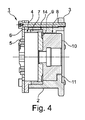
2 ハウジング
3 入力車
4 作動伝動装置
5 作動軸
6 入力リングギヤ
7 出力リングギヤ
8 第1の滑り軸受装置
9 フランジ
10 出力エレメント
11 伝動装置構成部分
12 軸方向溝
13 環状の溝
14 第2の滑り軸受装置
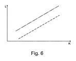
lk てこ腕長さ
K チェーン力
Claims (10)
- 内燃機関のシャフトの作動装置であって、
ハウジング(2)と、
該ハウジング(2)に結合された入力車(3)と、
作動伝動装置(4)と、
駆動されるべきシャフトとの結合のために設けられた出力エレメント(10)と、
前記ハウジング(2)内に前記出力エレメント(10)を支持するために設けられた滑り軸受装置(8)と、
を備えた作動装置において、
前記出力エレメント(10)は、該出力エレメント(10)に相対回動不能に結合されかつ該出力エレメント(10)を半径方向で超えて突出しているフランジ(9)を、駆動されるべきシャフトの軸方向で見て、前記作動伝動装置(4)と前記入力車(3)との間に有しており、前記滑り軸受装置(8)は、前記フランジ(9)に隣接して前記入力車(3)の側に配置されていることを特徴とする、内燃機関のシャフトの作動装置。 - 前記作動伝動装置(4)が、前記フランジ(9)に結合された出力リングギヤ(7)を有し、該出力リングギヤ(7)が、第2の滑り軸受装置(14)によって前記ハウジング(2)内に支持されていることを特徴とする、請求項1記載の作動装置。
- 前記両滑り軸受装置(8,14)が、互いに異なる直径を有することを特徴とする、請求項2記載の作動装置。
- 前記両滑り軸受装置(8,14)が、互いに異なる軸方向延在長さを有することを特徴とする、請求項2または3記載の作動装置。
- 軸方向で前記作動伝動装置(4)と前記入力車(3)との間に配置された第1の滑り軸受(8)が、第2の滑り軸受(14)よりも小さな直径と、第2の滑り軸受(14)よりも大きな軸方向延在長さとを有することを特徴とする、請求項3または4記載の作動装置。
- 前記出力エレメント(10)が、駆動されるべきシャフトの調節角度を制限するストッパディスクとして形成されていることを特徴とする、請求項1から5までのいずれか1項記載の作動装置。
- 前記作動伝動装置(4)が、3軸伝動装置、特にウェーブ伝動装置として構成されていることを特徴とする、請求項1から6までのいずれか1項記載の作動装置。
- 前記ハウジング(2)が、前記滑り軸受装置(8)の領域に、複数の軸方向溝(12)を有することを特徴とする、請求項1から7までのいずれか1項記載の作動装置。
- 前記ハウジング(2)が、前記滑り軸受装置(8)の領域に、周方向に延びる少なくとも1つの溝(13)を有することを特徴とする、請求項1から8までのいずれか1項記載の作動装置。
- 当該作動装置が、電気式のカムシャフト調整器の一部または内燃機関の圧縮比を変えるための装置の一部であることを特徴とする、請求項1から9までのいずれか1項記載の作動装置。
Applications Claiming Priority (3)
| Application Number | Priority Date | Filing Date | Title |
|---|---|---|---|
| DE102015217296.1 | 2015-09-10 | ||
| DE102015217296 | 2015-09-10 | ||
| PCT/DE2016/200420 WO2017041801A1 (de) | 2015-09-10 | 2016-09-07 | Nockenwellenversteller |
Publications (2)
| Publication Number | Publication Date |
|---|---|
| JP2018530695A JP2018530695A (ja) | 2018-10-18 |
| JP6800959B2 true JP6800959B2 (ja) | 2020-12-16 |
Family
ID=57003300
Family Applications (1)
| Application Number | Title | Priority Date | Filing Date |
|---|---|---|---|
| JP2018512528A Active JP6800959B2 (ja) | 2015-09-10 | 2016-09-07 | カムシャフト調整器 |
Country Status (5)
| Country | Link |
|---|---|
| EP (1) | EP3347578B1 (ja) |
| JP (1) | JP6800959B2 (ja) |
| CN (1) | CN108026799B (ja) |
| DE (1) | DE102016216927A1 (ja) |
| WO (1) | WO2017041801A1 (ja) |
Families Citing this family (4)
| Publication number | Priority date | Publication date | Assignee | Title |
|---|---|---|---|---|
| US10287932B2 (en) * | 2016-09-19 | 2019-05-14 | Schaeffler Technologies AG & Co. KG | Camshaft phasing system including idler gear phaser for internal combustion engines |
| DE102017115882B4 (de) | 2017-07-14 | 2023-11-09 | Schaeffler Technologies AG & Co. KG | Elektrischer Nockenwellenversteller zur variablen Einstellung der Ventilsteuerzeiten einer Brennkraftmaschine |
| DE102017128423A1 (de) | 2017-11-30 | 2019-06-06 | Schaeffler Technologies AG & Co. KG | Wellgetriebe |
| DE102018128930B4 (de) | 2018-11-19 | 2023-06-29 | Schaeffler Technologies AG & Co. KG | Wellgetriebe, Verfahren zur Herstellung eines Wellgetriebes und Nockenwellenversteller mit einem Wellgetriebe |
Family Cites Families (11)
| Publication number | Priority date | Publication date | Assignee | Title |
|---|---|---|---|---|
| US7089897B2 (en) * | 2002-07-11 | 2006-08-15 | Ina-Schaeffler Kg | Electrically driven camshaft adjuster |
| DE102004038681B4 (de) | 2004-08-10 | 2017-06-01 | Schaeffler Technologies AG & Co. KG | Elektromotorischer Nockenwellenversteller |
| JP4390078B2 (ja) | 2005-09-05 | 2009-12-24 | 株式会社デンソー | バルブタイミング調整装置 |
| JP4900286B2 (ja) * | 2008-03-04 | 2012-03-21 | 株式会社デンソー | バルブタイミング調整装置 |
| JP5288311B2 (ja) * | 2009-04-03 | 2013-09-11 | Ntn株式会社 | 可変バルブタイミング装置 |
| US8555836B2 (en) * | 2010-12-10 | 2013-10-15 | Delphi Technologies, Inc. | Electric drive camshaft phaser with torque rate limit at travel stops |
| US8516983B2 (en) | 2011-09-30 | 2013-08-27 | Delphi Technologies, Inc. | Harmonic drive camshaft phaser with a harmonic drive ring to prevent ball cage deflection |
| JP2013167181A (ja) * | 2012-02-15 | 2013-08-29 | Hitachi Automotive Systems Ltd | 内燃機関のバルブタイミング制御装置 |
| JP2014074388A (ja) * | 2012-10-05 | 2014-04-24 | Denso Corp | バルブタイミング調整装置 |
| WO2014092973A1 (en) * | 2012-12-10 | 2014-06-19 | Borgwarner Inc. | Electric motor driven simple planetary cam phaser |
| JP5862696B2 (ja) * | 2014-01-29 | 2016-02-16 | 株式会社日本自動車部品総合研究所 | バルブタイミング調整装置 |
-
2016
- 2016-09-07 EP EP16770885.8A patent/EP3347578B1/de active Active
- 2016-09-07 CN CN201680050942.8A patent/CN108026799B/zh active Active
- 2016-09-07 WO PCT/DE2016/200420 patent/WO2017041801A1/de not_active Ceased
- 2016-09-07 DE DE102016216927.0A patent/DE102016216927A1/de not_active Withdrawn
- 2016-09-07 JP JP2018512528A patent/JP6800959B2/ja active Active
Also Published As
| Publication number | Publication date |
|---|---|
| CN108026799A (zh) | 2018-05-11 |
| CN108026799B (zh) | 2020-06-30 |
| WO2017041801A1 (de) | 2017-03-16 |
| EP3347578B1 (de) | 2019-06-19 |
| DE102016216927A1 (de) | 2017-03-16 |
| EP3347578A1 (de) | 2018-07-18 |
| JP2018530695A (ja) | 2018-10-18 |
Similar Documents
| Publication | Publication Date | Title |
|---|---|---|
| JP6800959B2 (ja) | カムシャフト調整器 | |
| JP2021021479A (ja) | クラッチ装置 | |
| JP6820321B2 (ja) | 弾性的な歯車を有する伝動装置 | |
| US8622037B2 (en) | Harmonic drive camshaft phaser with a compact drive sprocket | |
| US20110030632A1 (en) | Harmonic Drive Camshaft Phaser with Improved Radial Stability | |
| US20190323577A1 (en) | Damper device | |
| WO2021020315A1 (ja) | クラッチ装置 | |
| JP2018505363A (ja) | ベルトプーリデカップラ | |
| WO2016093064A1 (ja) | 変速機構 | |
| CN109210132A (zh) | 减振装置 | |
| JP5139209B2 (ja) | 可変バルブタイミング装置 | |
| JP2009197980A (ja) | 変速機 | |
| JP2010038184A (ja) | 変速機 | |
| JP5180931B2 (ja) | ベルト式無段変速機 | |
| CN104514819A (zh) | 单向机械离合器系统及包括这种系统的交流发电机 | |
| JP2014196784A (ja) | Vベルト式無段変速機 | |
| WO2014038296A1 (ja) | 無段変速機 | |
| WO2017135047A1 (ja) | ベルト式無段変速機 | |
| JP2015021558A (ja) | 無段変速機 | |
| CN105090444B (zh) | 无级变速器 | |
| JP2014196780A (ja) | Vベルト式無段変速機 | |
| JPWO2024161768A5 (ja) | ||
| US8601904B2 (en) | Force transmission assembly and a control assembly including such an assembly | |
| JP6036282B2 (ja) | アクチュエータ | |
| CN104006090B (zh) | 设有穿过螺旋孔口作用的套筒连接的用于内燃机的机组的致动器 |
Legal Events
| Date | Code | Title | Description |
|---|---|---|---|
| A621 | Written request for application examination |
Free format text: JAPANESE INTERMEDIATE CODE: A621 Effective date: 20190904 |
|
| A131 | Notification of reasons for refusal |
Free format text: JAPANESE INTERMEDIATE CODE: A131 Effective date: 20200618 |
|
| A521 | Request for written amendment filed |
Free format text: JAPANESE INTERMEDIATE CODE: A523 Effective date: 20200910 |
|
| TRDD | Decision of grant or rejection written | ||
| A01 | Written decision to grant a patent or to grant a registration (utility model) |
Free format text: JAPANESE INTERMEDIATE CODE: A01 Effective date: 20201027 |
|
| A61 | First payment of annual fees (during grant procedure) |
Free format text: JAPANESE INTERMEDIATE CODE: A61 Effective date: 20201125 |
|
| R150 | Certificate of patent or registration of utility model |
Ref document number: 6800959 Country of ref document: JP Free format text: JAPANESE INTERMEDIATE CODE: R150 |
|
| R250 | Receipt of annual fees |
Free format text: JAPANESE INTERMEDIATE CODE: R250 |
|
| R250 | Receipt of annual fees |
Free format text: JAPANESE INTERMEDIATE CODE: R250 |
|
| R250 | Receipt of annual fees |
Free format text: JAPANESE INTERMEDIATE CODE: R250 |