(1)概要
以下の実施形態は、本発明の様々な実施形態の一つに過ぎない。以下の実施形態は、本発明の目的を達成できれば、設計等に応じて種々の変更が可能である。また、下記の実施形態等において説明する図1〜図11Bは、模式的な図であり、図1〜図11B中の各構成要素の大きさや厚さそれぞれの比が、必ずしも実際の寸法比を反映しているとは限らない。
(1) Outline The following embodiment is only one of various embodiments of the present invention. The following embodiments can be variously modified according to the design and the like as long as the object of the present invention can be achieved. Further, FIGS. 1 to 11B described in the following embodiments and the like are schematic views, and the ratio of the size and the thickness of each component in FIGS. 1 to 11B does not necessarily mean the actual dimensional ratio. It does not always reflect.
本実施形態の配線スイッチ構造は、図1に示すように、弾性部材2と操作部3とを備える。また、本実施形態の配線スイッチ構造は、例えば、配線器具であるスイッチ10に適用されて、スイッチ装置1を構成する。すなわち、スイッチ装置1は、配線スイッチ構造とスイッチ10とを備える。本実施形態では、スイッチ10は、図1に示すように、一例としてシーソー型スイッチである。しかし、スイッチ10は、ピアノハンドル型スイッチであってもよい。
As shown in FIG. 1, the wiring switch structure of the present embodiment includes an elastic member 2 and an operation unit 3. Further, the wiring switch structure of the present embodiment is applied to, for example, a switch 10 which is a wiring appliance to form a switch device 1. That is, the switch device 1 includes a wiring switch structure and a switch 10. In this embodiment, the switch 10 is a seesaw type switch as an example, as shown in FIG. However, the switch 10 may be a piano handle type switch.
弾性部材2は、スイッチ10のハンドル12を覆い、押圧を受けると弾性変形してハンドル12を搖動させる。操作部3は、図3に示すように、一表面(第1面30)に第1領域31及び第2領域32を有している。第1領域31又は第2領域32への押操作に応じて上記押圧を弾性部材2に与えてスイッチ10における接点11(図5及び図6参照)の開閉状態を切り替える。つまり、弾性部材2は、操作部3とスイッチ10のハンドル12との間に配置されている。
The elastic member 2 covers the handle 12 of the switch 10 and elastically deforms when pressed to cause the handle 12 to oscillate. As shown in FIG. 3, the operation unit 3 has a first region 31 and a second region 32 on one surface (first surface 30). The pressure is applied to the elastic member 2 in response to the pressing operation on the first region 31 or the second region 32 to switch the open / closed state of the contact 11 (see FIGS. 5 and 6) in the switch 10. That is, the elastic member 2 is arranged between the operation unit 3 and the handle 12 of the switch 10.
ここで言う第1領域31及び第2領域32は、図3中において想像線(一点鎖線)で図示されているが、厳密な境界線を示すものではなく、おおむねそれらの領域内を押すことで、スイッチ10の接点11の状態が切り替わるものである。
Although the first region 31 and the second region 32 referred to here are illustrated by imaginary lines (dashed-dotted lines) in FIG. 3, they do not show strict boundaries and are generally pressed within those regions. , The state of the contact 11 of the switch 10 is switched.
本実施形態のスイッチ装置1では、利用者によって操作部3の第1領域31が押された状態のとき(図3参照)、スイッチ10の接点11が閉状態(オン)にある。この状態から利用者によって操作部3の第2領域32が押されると、接点11が閉状態(オン)から開状態(オフ)に切り替わる。なお、スイッチ10がピアノハンドル型スイッチである場合には、操作部3の第1領域31及び第2領域32の一方のみに対して押操作される度に、スイッチ10の接点11の開閉状態が切り替わることになる。
In the switch device 1 of the present embodiment, when the first region 31 of the operation unit 3 is pressed by the user (see FIG. 3), the contact 11 of the switch 10 is in the closed state (on). When the second region 32 of the operation unit 3 is pushed by the user from this state, the contact 11 is switched from the closed state (on) to the open state (off). When the switch 10 is a piano handle type switch, the open / closed state of the contact 11 of the switch 10 is changed each time the switch 10 is pressed against only one of the first region 31 and the second region 32 of the operation unit 3. It will switch.
ここで、本実施形態の弾性部材2は、図1、図9A、及び図9Bに示すように、接触部20と第1側部21と第2側部22と第1連結部23と第2連結部24とを有している。接触部20は、上記押圧を受けてハンドル12と接触する。第1側部21は、第1領域31と第2領域32とが並ぶ第1方向D1におけるハンドル12の両端部の少なくとも一方と対向する。本実施形態の弾性部材2は、一例として、一対の第1側部21,21を有しており、一対の第1側部21,21が、第1方向D1におけるハンドル12の両端部(図示例では上下両端部)と、それぞれ一対一で対向する。
Here, the elastic member 2 of the present embodiment has a contact portion 20, a first side portion 21, a second side portion 22, a first connecting portion 23, and a second, as shown in FIGS. 1, 9A, and 9B. It has a connecting portion 24. The contact portion 20 receives the above pressure and comes into contact with the handle 12. The first side portion 21 faces at least one of both end portions of the handle 12 in the first direction D1 in which the first region 31 and the second region 32 are aligned. As an example, the elastic member 2 of the present embodiment has a pair of first side portions 21 and 21, and the pair of first side portions 21 and 21 are both end portions of the handle 12 in the first direction D1 (FIG. In the example, the upper and lower ends) face each other on a one-to-one basis.
第2側部22は、操作部3の第1面30の前方から見て、第1方向D1と直交する第2方向D2におけるハンドル12の両端部の少なくとも一方と対向する。なお、ここで言う「直交」は、幾何学上の「直交」よりも広い意味であり、厳密な「直交」でなくてもよく、略直交(互いに交わる角度が例えば90°±5°)でもよい。本実施形態の弾性部材2は、一例として、一対の第2側部22,22を有しており、一対の第2側部22,22が、第2方向D2におけるハンドル12の両端部(図示例では左右両端部)に、それぞれ一対一で対向する。
The second side portion 22 faces at least one of both ends of the handle 12 in the second direction D2 orthogonal to the first direction D1 when viewed from the front of the first surface 30 of the operation portion 3. Note that "orthogonal" here has a broader meaning than geometrical "orthogonal" and does not have to be strictly "orthogonal", even if it is substantially orthogonal (the angle at which they intersect each other is, for example, 90 ° ± 5 °). Good. The elastic member 2 of the present embodiment has a pair of second side portions 22, 22 as an example, and the pair of second side portions 22, 22 are both end portions of the handle 12 in the second direction D2 (FIG. In the example, the left and right ends) face each other on a one-to-one basis.
図示例では、第1方向D1は、上下方向に相当し、第2方向D2は、左右方向に相当するが、特に限定されない。第1領域31と第2領域32とが並ぶ第1方向D1は、例えば、左右方向に相当してもよい。この場合、第2方向D2は、上下方向に相当する。なお、第1方向D1は、スイッチ装置1の前方から見たときに、スイッチ10のハンドル12が搖動する方向に沿った方向とも言える。
In the illustrated example, the first direction D1 corresponds to the vertical direction, and the second direction D2 corresponds to the left-right direction, but is not particularly limited. The first direction D1 in which the first region 31 and the second region 32 are lined up may correspond to, for example, the left-right direction. In this case, the second direction D2 corresponds to the vertical direction. The first direction D1 can be said to be a direction along the direction in which the handle 12 of the switch 10 swings when viewed from the front of the switch device 1.
第1連結部23は、接触部20と第1側部21とを連結している。つまり、接触部20と第1側部21とは、第1連結部23を間に介して一体となって形成されている。第2連結部24は、接触部20と第2側部22とを連結している。つまり、接触部20と第2側部22とは、第2連結部24を間に介して一体となって形成されている。そして、第1連結部23は、第2連結部24よりも可撓性が大きい。
The first connecting portion 23 connects the contact portion 20 and the first side portion 21. That is, the contact portion 20 and the first side portion 21 are integrally formed with the first connecting portion 23 interposed therebetween. The second connecting portion 24 connects the contact portion 20 and the second side portion 22. That is, the contact portion 20 and the second side portion 22 are integrally formed with the second connecting portion 24 interposed therebetween. The first connecting portion 23 is more flexible than the second connecting portion 24.
この構成によれば、利用者によって操作部3の第1領域31(又は第2領域32)が押操作されると、弾性部材2が弾性的に変形するとともに、操作部3からの押圧が弾性部材2超しにハンドル12へ伝わり接点11の開閉状態が切り替わる。ただし、第1連結部23が第2連結部24よりも可撓性が大きい。そのため、弾性部材2は、第2連結部24よりも第1連結部23が主として弾性変形することになる。一方で、第2連結部24は第1連結部23に比べれば弾性変形し難い。したがって、第1連結部23と第2連結部24の両方が略均一に押し潰れるように弾性変形してしまう場合に比べて、利用者に対して、より良い操作感(操作部3を押した時の感触)を与えることができる。その結果、操作感の向上を図ることができる。
According to this configuration, when the first region 31 (or the second region 32) of the operation unit 3 is pushed by the user, the elastic member 2 is elastically deformed and the pressure from the operation unit 3 is elastic. It is transmitted to the handle 12 beyond the member 2 and the open / closed state of the contact 11 is switched. However, the first connecting portion 23 is more flexible than the second connecting portion 24. Therefore, in the elastic member 2, the first connecting portion 23 is mainly elastically deformed rather than the second connecting portion 24. On the other hand, the second connecting portion 24 is less likely to be elastically deformed than the first connecting portion 23. Therefore, compared to the case where both the first connecting portion 23 and the second connecting portion 24 are elastically deformed so as to be crushed substantially uniformly, a better operation feeling (pressing the operation unit 3) is given to the user. Feeling of time) can be given. As a result, the operability can be improved.
ところで、本実施形態のスイッチ装置1は、一例として、屋外の造営材(例えば壁材)の表面に埋め込み配置されることを想定している。そのため、スイッチ装置1に防水機能を持たせるために、弾性部材2は、図1に示すように、スイッチ10及び取付枠4を前方から覆うように形成された防水パッキンである。ただし、本実施形態のスイッチ装置1において、防水機能は必須の機能ではない。例えば、スイッチ装置1が屋内専用のスイッチ装置であれば、弾性部材2は、スイッチ10のハンドル12のみを前方から覆うように形成されていてもよい。
By the way, it is assumed that the switch device 1 of the present embodiment is embedded in the surface of an outdoor construction material (for example, a wall material) as an example. Therefore, in order to give the switch device 1 a waterproof function, the elastic member 2 is a waterproof packing formed so as to cover the switch 10 and the mounting frame 4 from the front, as shown in FIG. However, in the switch device 1 of the present embodiment, the waterproof function is not an essential function. For example, if the switch device 1 is a switch device dedicated to indoor use, the elastic member 2 may be formed so as to cover only the handle 12 of the switch 10 from the front.
(2)詳細
(2.1)全体構成
以下、本実施形態の配線スイッチ構造、及びスイッチ装置1について、図1〜図11Bを参照して詳しく説明する。スイッチ装置1は、上述したように、配線スイッチ構造(弾性部材2及び操作部3)と、スイッチ10とを備える。また、スイッチ装置1は、図1に示すように、取付枠4と、組立枠5と、カバー体6とを更に備える。
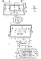
(2) Details (2.1) Overall configuration Hereinafter, the wiring switch structure and the switch device 1 of the present embodiment will be described in detail with reference to FIGS. 1 to 11B. As described above, the switch device 1 includes a wiring switch structure (elastic member 2 and operation unit 3) and a switch 10. Further, as shown in FIG. 1, the switch device 1 further includes a mounting frame 4, an assembly frame 5, and a cover body 6.
以下では、スイッチ装置1の上下、左右、前後の方向を、図1に図示されている上下、左右、前後の矢印を用いて規定して説明する。これらの矢印は、単に説明を補助する目的で記載しているに過ぎず、実体を伴わない。また、これらの方向は、スイッチ装置1の使用方向を限定する趣旨ではない。
In the following, the vertical, horizontal, and front-back directions of the switch device 1 will be defined and described with reference to the up-down, left-right, and front-back arrows shown in FIG. These arrows are for the purpose of assisting explanation only and are not accompanied by substance. Further, these directions are not intended to limit the direction in which the switch device 1 is used.
(2.2)スイッチ
スイッチ10は、上の「(1)概要」の欄で説明したように、一例として、シーソー型スイッチである。スイッチ10は、図1に示すように、ハンドル12と、スイッチ本体13とで構成される。
(2.2) Switch The switch 10 is a seesaw type switch as an example, as described in the column of "(1) Overview" above. As shown in FIG. 1, the switch 10 includes a handle 12 and a switch body 13.
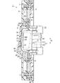
スイッチ本体13は、図1及び図2に示すように、上下方向に長尺の略矩形箱状に形成されている。ハンドル12は、スイッチ10の前方から見たときに、スイッチ本体13の前面において、第1方向D1(上下方向)に沿って搖動可能に取り付けられている。スイッチ本体13は、図5及び図6に示すように、その内部に、接点11及び接点11の切替機構を有している。ハンドル12の一面120(前面)において、上側領域又は下側領域が押し込まれると、ハンドル12が搖動し、スイッチ本体13の接点11は、閉状態と開状態とで切り替えられる。本実施形態では、図5に示すように、一面120の上側領域が押し込まれると、接点11が閉状態(オン状態)となり、逆に、図6に示すように、一面120の下側領域が押し込まれると、接点11が開状態(オフ状態)となる。
As shown in FIGS. 1 and 2, the switch body 13 is formed in a substantially rectangular box shape that is long in the vertical direction. The handle 12 is rotatably attached to the front surface of the switch body 13 along the first direction D1 (vertical direction) when viewed from the front of the switch 10. As shown in FIGS. 5 and 6, the switch main body 13 has a contact 11 and a contact 11 switching mechanism inside. When the upper region or the lower region is pushed on one side 120 (front surface) of the handle 12, the handle 12 swings, and the contact 11 of the switch body 13 is switched between the closed state and the open state. In the present embodiment, as shown in FIG. 5, when the upper region of the one surface 120 is pushed in, the contact 11 is closed (on state), and conversely, as shown in FIG. 6, the lower region of the one surface 120 is opened. When pushed in, the contact 11 is in the open state (off state).
本実施形態では、接点11は、固定接点110と、可動接点111とを有し、ハンドル12の搖動に応じて可動接触子112が変位して、固定接点110に対する可動接点111の接離が行われる。なお、このような接点11の切替機構は、従来周知であるからスイッチ本体13の内部構造等の詳細な図示及び説明は省略する。
In the present embodiment, the contact 11 has a fixed contact 110 and a movable contact 111, and the movable contact 112 is displaced according to the swing of the handle 12, and the movable contact 111 is brought into contact with and detached from the fixed contact 110. It is said. Since such a contact 11 switching mechanism is well known in the past, detailed illustration and description of the internal structure of the switch body 13 and the like will be omitted.
このスイッチ10は、電源(例えば商用電源)と負荷(例えば照明負荷)とを電気的に接続する給電路の途中に接続される。スイッチ10の接点11がオンになると、負荷に電力が供給され、負荷が照明負荷であれば点灯する。スイッチ10の接点11がオフになると、負荷への電力供給が遮断され、負荷が照明負荷であれば消灯する。
The switch 10 is connected in the middle of a power supply path that electrically connects a power source (for example, a commercial power source) and a load (for example, a lighting load). When the contact 11 of the switch 10 is turned on, power is supplied to the load, and if the load is a lighting load, it lights up. When the contact 11 of the switch 10 is turned off, the power supply to the load is cut off, and if the load is a lighting load, the light is turned off.
ハンドル12は、図1に示すように、その一面120の上側において、ランプカバー121を有していてもよい。この場合、スイッチ本体13の内部にはランプ(不図示)が収容されており、当該ランプの発光は、ランプカバー121を透過して前方に出射されてもよい。スイッチ本体13の内部に収容されるランプとして、例えば接点11がオフ状態で白色(又は緑色)発光する発光ダイオードと、接点11がオン状態で赤色発光する発光ダイオードとが用いられていることが望ましい。
As shown in FIG. 1, the handle 12 may have a lamp cover 121 on the upper side of one side 120 thereof. In this case, a lamp (not shown) is housed inside the switch main body 13, and the light emission of the lamp may be emitted forward through the lamp cover 121. As the lamp housed inside the switch body 13, for example, it is desirable that a light emitting diode that emits white (or green) light when the contact 11 is off and a light emitting diode that emits red light when the contact 11 is on are used. ..
スイッチ本体13は、図1に示すように、第1ブロック13Aと第2ブロック13Bを有している。第1ブロック13Aと第2ブロック13Bとは、一対の取付金具13Cによって、前後方向に組み付けられていて、全体として略矩形の箱体を構成する。
As shown in FIG. 1, the switch body 13 has a first block 13A and a second block 13B. The first block 13A and the second block 13B are assembled in the front-rear direction by a pair of mounting brackets 13C, and form a substantially rectangular box body as a whole.
第1ブロック13Aは、後面が開放した略矩形箱状に形成されている。第1ブロック13Aは、主にハンドル12を収容している。ただし、第1ブロック13Aは、その前面に設けられている露出孔を通じて、ハンドル12の一面120を露出する。第1ブロック13Aは、左右方向から見て、その前方部位130が後方部位131に対して前方に凸となるように突出し、ハンドル12の一面120を露出する露出孔は、凸となる当該前方部位130の前面に設けられている。
The first block 13A is formed in a substantially rectangular box shape with an open rear surface. The first block 13A mainly houses the handle 12. However, the first block 13A exposes one side 120 of the handle 12 through an exposed hole provided in the front surface thereof. The front portion 130 of the first block 13A protrudes forward so as to be convex forward with respect to the rear portion 131 when viewed from the left-right direction, and the exposed hole exposing one surface 120 of the handle 12 is the convex front portion. It is provided on the front surface of the 130.
各取付金具13Cは、上下方向から見て略U字形の帯板状に形成されている。各取付金具13Cは、図1に示すように、上下方向に貫通するスリット13Dを有している。なお、図1では、上側の取付金具13Cのスリット13Dのみが図示されている。各スリット13Dには、(後述の)組立枠5の取付片51,52のうちの対応する一方が挿入する。
Each mounting bracket 13C is formed in a substantially U-shaped strip shape when viewed from the vertical direction. As shown in FIG. 1, each mounting bracket 13C has a slit 13D penetrating in the vertical direction. In FIG. 1, only the slit 13D of the upper mounting bracket 13C is shown. The corresponding one of the mounting pieces 51 and 52 of the assembly frame 5 (described later) is inserted into each slit 13D.
第2ブロック13Bは、前面が開放した矩形箱状に形成されている。第2ブロック13Bは、主に接点11及び接点11の切替機構を収容している。上下方向における第2ブロック13Bの寸法は、第1ブロック13Aの後方部位131の寸法とおおむね同じであり、第1ブロック13Aの前方部位130の寸法よりも大きい。第2ブロック13Bは、図4に示すように、その後面において、電線(不図示)を挿入するための電線挿入孔132を上下端付近の各々に2個ずつ(合計4個)有している。
The second block 13B is formed in a rectangular box shape with an open front surface. The second block 13B mainly houses the contact 11 and the switching mechanism of the contact 11. The dimensions of the second block 13B in the vertical direction are substantially the same as the dimensions of the rear portion 131 of the first block 13A, and are larger than the dimensions of the front portion 130 of the first block 13A. As shown in FIG. 4, the second block 13B has two electric wire insertion holes 132 (four in total) near the upper and lower ends on the rear surface thereof for inserting electric wires (not shown). ..
また、第2ブロック13Bは、その内部に、接点11の固定接点110側の端子又は可動接点111側の端子にそれぞれ電気的に接続された速結構造の接続端子(ねじなし端子)を4個有している。4個の接続端子は、4個の電線挿入孔132と一対一に対向して配置されており、いずれかの電線挿入孔132に挿入された電線の芯線は、対応する接続端子に機械的及び電気的に接続される。
Further, the second block 13B has four connection terminals (screwless terminals) having a quick connection structure, which are electrically connected to the terminals on the fixed contact 110 side or the terminals on the movable contact 111 side of the contact 11 inside. Have. The four connection terminals are arranged one-to-one with the four wire insertion holes 132, and the core wire of the wire inserted into any of the wire insertion holes 132 is mechanically and to the corresponding connection terminal. It is electrically connected.
なお、第2ブロック13Bは、図4に示すように、その後面における上下端の各々において、内部に通じている差込口133を、更に有している。例えば、マイナスドライバー等の工具の先端を差込口133に差し込むことで、電線挿入孔132に挿入されている電線の芯線に食い込んでいる接続端子の鎖錠部を当該芯線から引き離して、スイッチ本体13から電線を引き抜くことができる。
As shown in FIG. 4, the second block 13B further has an insertion port 133 that leads to the inside at each of the upper and lower ends on the rear surface. For example, by inserting the tip of a tool such as a flat-blade screwdriver into the insertion port 133, the locking portion of the connection terminal that bites into the core wire of the electric wire inserted in the electric wire insertion hole 132 is separated from the core wire, and the switch main body is separated. The electric wire can be pulled out from 13.
(2.3)取付枠
取付枠4は、図1に示すように、略中央に窓孔40を有した、上下方向に長尺の矩形枠の板状に形成されている。取付枠4は、例えば合成樹脂材料により形成されている。窓孔40は、取付枠4を前後方向に貫通した略矩形状の孔であり、スイッチ10が挿入されて配置されるための空間である。窓孔40の周縁部とスイッチ10との間には、ある程度の隙間できる程度に、窓孔40の上下寸法及び左右寸法は、例えば、スイッチ10の上下寸法及び左右寸法よりも大きく規定されている。
(2.3) Mounting Frame As shown in FIG. 1, the mounting frame 4 is formed in the shape of a plate having a long rectangular frame in the vertical direction and having a window hole 40 at substantially the center. The mounting frame 4 is made of, for example, a synthetic resin material. The window hole 40 is a substantially rectangular hole that penetrates the mounting frame 4 in the front-rear direction, and is a space for inserting and arranging the switch 10. The vertical and horizontal dimensions of the window hole 40 are defined to be larger than, for example, the vertical and horizontal dimensions of the switch 10 so that there is a certain gap between the peripheral edge of the window hole 40 and the switch 10. ..
取付枠4は、図1に示すように、その前面の上下端の各々において、左右方向の中央に、前方へ突出して周囲よりも肉厚が大きくなった直方体状の段部41を有している。各段部41には、前後方向に貫通するねじ孔42が設けられている。このねじ孔42には、カバー体6及び弾性部材2を取付枠4へねじ止めするための2本のねじ7が、それぞれねじ込まれる。
As shown in FIG. 1, the mounting frame 4 has a rectangular parallelepiped stepped portion 41 at each of the upper and lower ends of the front surface thereof, which protrudes forward and is thicker than the periphery at the center in the left-right direction. There is. Each step 41 is provided with a screw hole 42 penetrating in the front-rear direction. Two screws 7 for screwing the cover body 6 and the elastic member 2 to the mounting frame 4 are screwed into the screw holes 42, respectively.
また、取付枠4は、図1に示すように、上端の段部41の下近傍、及び下端の段部41の上近傍の各々に、左右方向に長尺の長孔43を有している。長孔43は、取付枠4を前後方向に貫通している。取付枠4は、2本のねじ(不図示)を、それぞれ2個の長孔43に通し、例えば造営材の裏側に埋め込み設置されているスイッチボックス、あるいは造営材の裏側に配置される挟み金具に、ねじ止めすることで造営材に固定される。
Further, as shown in FIG. 1, the mounting frame 4 has elongated holes 43 in the left-right direction in each of the lower vicinity of the upper end step portion 41 and the upper vicinity of the lower end step portion 41. .. The elongated hole 43 penetrates the mounting frame 4 in the front-rear direction. In the mounting frame 4, two screws (not shown) are passed through each of the two elongated holes 43, and for example, a switch box embedded in the back side of the construction material or a sandwiching metal fitting arranged on the back side of the construction material. It is fixed to the construction material by screwing.
なお、取付枠4は、図1及び図2に示すように、下端部の左右方向における中央に、下方へ突出する突出片44を有している。取付枠4を造営材から取り外す際には、スイッチボックス又は挟み金具等に締結されていたねじを緩め、指先又は工具等の先端を、この突出片44に引っ掛けることで造営材の表面から容易に引き外すことができる。
As shown in FIGS. 1 and 2, the mounting frame 4 has a protruding piece 44 projecting downward at the center of the lower end portion in the left-right direction. When removing the mounting frame 4 from the construction material, loosen the screws fastened to the switch box or the sandwiching metal fittings, and hook the tip of the fingertip or tool on the protruding piece 44 to easily remove it from the surface of the construction material. It can be pulled out.
(2.4)組立枠
組立枠5は、図1及び図2に示すように、略中央に挿入口50を有した、上下方向に長尺の矩形枠の板状に形成されている。組立枠5は、例えば金属材料により形成されている。組立枠5は、スイッチ10を支持するように構成されている。挿入口50は、組立枠5を前後方向に貫通した略矩形状の孔である。挿入口50は、前後方向から見たときに、スイッチ10の第1ブロック13Aにおける凸となる前方部位130の上下及び左右方向の寸法よりもやや大きい開口面積を有する。ただし、挿入口50は、スイッチ10の第1ブロック13Aにおける後方部位131や第2ブロック13Bの上下方向の寸法よりも小さい開口面積を有する。要するに、挿入口50は、ハンドル12の一面120、及びハンドル12の側方を囲む第1ブロック13Aの前方部位130のみを、組立枠5の前面よりも前方に露出するように構成されている。
(2.4) Assembly Frame As shown in FIGS. 1 and 2, the assembly frame 5 is formed in the shape of a plate of a rectangular frame elongated in the vertical direction, which has an insertion port 50 at substantially the center. The assembly frame 5 is made of, for example, a metal material. The assembly frame 5 is configured to support the switch 10. The insertion port 50 is a substantially rectangular hole that penetrates the assembly frame 5 in the front-rear direction. The insertion port 50 has an opening area slightly larger than the vertical and horizontal dimensions of the convex front portion 130 in the first block 13A of the switch 10 when viewed from the front-rear direction. However, the insertion port 50 has an opening area smaller than the vertical dimension of the rear portion 131 and the second block 13B in the first block 13A of the switch 10. In short, the insertion port 50 is configured so that only one side 120 of the handle 12 and the front portion 130 of the first block 13A surrounding the side of the handle 12 are exposed in front of the front surface of the assembly frame 5.
組立枠5は、図1及び図2に示すように、挿入口50の上縁部分と下縁部分とに、組立枠5の中心に向かって突出する取付片51,52を有する。ただし、挿入口50の上縁部分の上近傍には、略U字状に貫通する差込孔53が設けられていて、この上縁部分は、上方に向かって凸となるように緩やかに湾曲している。スイッチ10を組立枠5に組み付ける際には、例えば、スイッチ10の前方部位130を組立枠5の後方から挿入口50に挿入させて、下縁部分の取付片52を、スイッチ10の下側のスリット13Dに係止させる。その状態から、マイナスドライバー等の工具の先端を差込孔53に差し込んで、挿入口50の上縁部分を下方へ塑性変形させる(かしめる)。その結果、上縁部分の取付片51がスイッチ10の上側のスリット13Dに係止して、スイッチ10が組立枠5に固定される。
As shown in FIGS. 1 and 2, the assembly frame 5 has mounting pieces 51 and 52 projecting toward the center of the assembly frame 5 at the upper edge portion and the lower edge portion of the insertion port 50. However, an insertion hole 53 penetrating in a substantially U shape is provided in the vicinity of the upper edge portion of the insertion port 50, and the upper edge portion is gently curved so as to be convex upward. doing. When assembling the switch 10 to the assembly frame 5, for example, the front portion 130 of the switch 10 is inserted into the insertion slot 50 from the rear of the assembly frame 5, and the mounting piece 52 of the lower edge portion is inserted under the switch 10. It is locked in the slit 13D. From that state, the tip of a tool such as a flat-blade screwdriver is inserted into the insertion hole 53, and the upper edge portion of the insertion port 50 is plastically deformed (caulked) downward. As a result, the mounting piece 51 at the upper edge portion is locked to the slit 13D on the upper side of the switch 10, and the switch 10 is fixed to the assembly frame 5.
なお、組立枠5は、図1及び図2に示すように、上端近傍及び下端近傍の各々における左右方向の中央において、前後方向に貫通した挿通孔54を有している。スイッチ10が組立枠5に組み付けられた状態で、2本のタッピンねじ8を挿通孔54,54にそれぞれ挿通させ、更に弾性部材2の孔部25,25に挿通させて、カバー体6の第1ボス62にあるねじ孔にねじ込むことで、組立枠5が弾性部材2及びカバー体6に固定される。
As shown in FIGS. 1 and 2, the assembly frame 5 has an insertion hole 54 penetrating in the front-rear direction at the center in the left-right direction in each of the vicinity of the upper end and the vicinity of the lower end. With the switch 10 assembled to the assembly frame 5, two tapping screws 8 are inserted into the insertion holes 54 and 54, respectively, and further inserted into the holes 25 and 25 of the elastic member 2 to form the cover body 6. The assembly frame 5 is fixed to the elastic member 2 and the cover body 6 by screwing into the screw hole in the boss 62.
(2.5)弾性部材
弾性部材2は、図1、図2、図5、図6、図8、図9A及び図9Bに示すように、上下方向に長尺で、かつ後面が開放された、全体としてへん平な略矩形箱状に形成されている。弾性部材2は、例えば、軟質の塩化ビニルを材料とし、射出成型により形成された、単一の成型品である。弾性部材2は、例えば、薄膜状に形成されている。弾性部材2は、例えば、透光性を有していてもよい。本実施形態の弾性部材2は、被覆部2Aと、基部2Bとから構成されている。
(2.5) Elastic member As shown in FIGS. 1, 2, 5, 6, 8, 9A and 9B, the elastic member 2 is long in the vertical direction and has an open rear surface. , It is formed in a flat, substantially rectangular box shape as a whole. The elastic member 2 is, for example, a single molded product formed by injection molding using soft vinyl chloride as a material. The elastic member 2 is formed in a thin film shape, for example. The elastic member 2 may have, for example, translucency. The elastic member 2 of the present embodiment is composed of a covering portion 2A and a base portion 2B.
まず被覆部2Aについて説明する。被覆部2Aは、その後面が開放された矩形箱状に形成されている。被覆部2Aは、へん平な略矩形箱状の基部2Bにおける上下及び左右方向の中央に配置されている。被覆部2Aは、その前面が、基部2Bの前面よりも前方に位置するように凸となっている。被覆部2Aは、組立枠5の挿入口50から突き出ているスイッチ10のハンドル12及び第1ブロック13Aの前方部位130を、これらの前方及び側方(上下左右方向)から覆うように構成されている。
First, the covering portion 2A will be described. The covering portion 2A is formed in a rectangular box shape with an open rear surface. The covering portion 2A is arranged at the center in the vertical and horizontal directions in the flat substantially rectangular box-shaped base portion 2B. The front surface of the covering portion 2A is convex so as to be located in front of the front surface of the base portion 2B. The covering portion 2A is configured to cover the handle 12 of the switch 10 and the front portion 130 of the first block 13A protruding from the insertion port 50 of the assembly frame 5 from the front and sides (up, down, left, and right directions) of these. There is.
被覆部2Aは、図9A及び図9Bに示すように、接触部20と、一対の第1側部21と、一対の第2側部22と、一対の第1連結部23と、一対の第2連結部24とを有しており、これらが一体となって形成されることで、後面が開放した矩形箱状となっている。
As shown in FIGS. 9A and 9B, the covering portion 2A includes a contact portion 20, a pair of first side portions 21, a pair of second side portions 22, a pair of first connecting portions 23, and a pair of first side portions. It has two connecting portions 24, and by forming them integrally, it has a rectangular box shape with an open rear surface.
接触部20は、おおむね矩形の薄膜状に形成されており、その厚み方向が前後方向に沿うように配置され、ハンドル12の一面120と対向する。すなわち、接触部20は、操作部3から押圧を受けて、主にハンドル12と接触する部位である。
The contact portion 20 is formed in a substantially rectangular thin film shape, is arranged so that the thickness direction thereof is along the front-rear direction, and faces one surface 120 of the handle 12. That is, the contact portion 20 is a portion that receives pressure from the operation portion 3 and mainly contacts the handle 12.
一対の第1側部21は、互いに同じ構造を有しており、おおむね左右方向に長尺で、かつ矩形の薄膜状に形成されている。一対の第1側部21は、その厚み方向が上下方向に沿うように配置され、第1方向D1(図示例では上下方向)におけるハンドル12の両端部(上下両端部)と対向する。ただし、本実施形態では、ハンドル12の上下両端部が第1ブロック13Aの前方部位130に覆われている。したがって、各第1側部21は、第1ブロック13Aを間に介して、ハンドル12の対応する端部と対向する。
The pair of first side portions 21 have the same structure as each other, and are formed in a rectangular thin film shape that is generally elongated in the left-right direction. The pair of first side portions 21 are arranged so that their thickness directions are along the vertical direction, and face both end portions (upper and lower end portions) of the handle 12 in the first direction D1 (vertical direction in the illustrated example). However, in the present embodiment, the upper and lower ends of the handle 12 are covered with the front portion 130 of the first block 13A. Therefore, each first side portion 21 faces the corresponding end portion of the handle 12 with the first block 13A in between.
一対の第2側部22は、互いに同じ構造を有しており、おおむね上下方向に長尺で、かつ矩形の薄膜状に形成されている。一対の第2側部22は、その厚み方向が左右方向に沿うように配置され、第2方向D2(図示例では左右方向)におけるハンドル12の両端部(左右両端部)と対向する。ただし、本実施形態では、ハンドル12の左右両端部が第1ブロック13Aの前方部位130に覆われている。したがって、各第2側部22は、第1ブロック13Aを間に介して、ハンドル12の対応する端部と対向する。
The pair of second side portions 22 have the same structure as each other, and are formed in a rectangular thin film shape that is generally elongated in the vertical direction. The pair of second side portions 22 are arranged so that their thickness directions are along the left-right direction, and face both end portions (left-right end portions) of the handle 12 in the second direction D2 (left-right direction in the illustrated example). However, in the present embodiment, both the left and right ends of the handle 12 are covered with the front portion 130 of the first block 13A. Therefore, each second side portion 22 faces the corresponding end portion of the handle 12 with the first block 13A in between.
一対の第1連結部23は、互いに同じ構造を有しており、おおむね左右方向に長尺で、かつ矩形の薄膜状に形成されている。一対の第1連結部23の各々は、図5及び図6に示すように、接触部20と、対応する第1側部21とを連結するための部位である。すなわち、上側の第1連結部23は、接触部20と、上側の第1側部21とを連結し、下側の第1連結部23は、接触部20と、下側の第1側部21とを連結している。左右方向における各第1連結部23の寸法は、接触部20の寸法と略同じであり、また、第1側部21の寸法と略同じである。
The pair of first connecting portions 23 have the same structure as each other, and are formed in a rectangular thin film shape that is generally long in the left-right direction. Each of the pair of first connecting portions 23 is a portion for connecting the contact portion 20 and the corresponding first side portion 21 as shown in FIGS. 5 and 6. That is, the upper first connecting portion 23 connects the contact portion 20 and the upper first side portion 21, and the lower first connecting portion 23 connects the contact portion 20 and the lower first side portion. 21 is connected. The dimensions of each first connecting portion 23 in the left-right direction are substantially the same as the dimensions of the contact portion 20, and are substantially the same as the dimensions of the first side portion 21.
薄膜状の各第1連結部23は、第2方向D2(左右方向)から見たときに、例えば、その表面及び裏面がアール形状に形成された断面を有している(図5及び図6参照)。すなわち、各第1連結部23は、スイッチ10から離れる方向に凸となるように湾曲している。
Each of the thin film-shaped first connecting portions 23 has a cross section in which, for example, the front surface and the back surface thereof are formed in a round shape when viewed from the second direction D2 (left-right direction) (FIGS. 5 and 6). reference). That is, each first connecting portion 23 is curved so as to be convex in the direction away from the switch 10.
一対の第2連結部24は、互いに同じ構造を有しており、おおむね上下方向に長尺で、かつ矩形の薄膜状に形成されている。一対の第2連結部24の各々は、図8に示すように、接触部20と、対応する第1側部21とを連結するための部位である。すなわち、右側の第2連結部24は、接触部20と、右側の第2側部22とを連結し、左側の第2連結部24は、接触部20と、左側の第2側部22とを連結している。上下方向における各第2連結部24の寸法は、接触部20の寸法と略同じであり、また、第2側部22の寸法と略同じである。
The pair of second connecting portions 24 have the same structure as each other, and are formed in a rectangular thin film shape that is generally elongated in the vertical direction. As shown in FIG. 8, each of the pair of second connecting portions 24 is a portion for connecting the contact portion 20 and the corresponding first side portion 21. That is, the second connecting portion 24 on the right side connects the contact portion 20 and the second side portion 22 on the right side, and the second connecting portion 24 on the left side connects the contact portion 20 and the second side portion 22 on the left side. Are connected. The dimensions of each of the second connecting portions 24 in the vertical direction are substantially the same as the dimensions of the contact portion 20, and are substantially the same as the dimensions of the second side portion 22.
薄膜状の各第2連結部24は、第1方向D1(上下方向)から見たときに、例えば、その表面及び裏面がアール形状に形成された断面を有している(図8参照)。すなわち、各第2連結部24は、スイッチ10から離れる方向に凸となるように湾曲している。
Each of the thin film-shaped second connecting portions 24 has a cross section in which, for example, the front surface and the back surface thereof are formed in a rounded shape when viewed from the first direction D1 (vertical direction) (see FIG. 8). That is, each second connecting portion 24 is curved so as to be convex in the direction away from the switch 10.
ここで、各第1連結部23は、各第2連結部24よりも可撓性が大きく構成されている。具体的には、図11A及び図11Bに示すように、各第1連結部23の厚みW1が、各第2連結部24の厚みW2よりも小さくなるように、互いの寸法関係が規定されている。一例として、厚みW1と厚みW2との比は、0.6〜0.8:1であることが好ましく、特に0.7:1であることが好ましい。例えば、厚みW1が0.7mmであり、厚みW2が1mmであってもよい。なお、本実施形態の被覆部2Aでは、厚みW1以外、すなわち、接触部20、第1側部21、第2側部22、及び第2連結部24の厚みは、全て、例えば1mmである。ただし、少なくとも、各第1連結部23が各第2連結部24よりも可撓性が大きければ、これらの厚みは、特に限定されるものではない。
Here, each first connecting portion 23 is configured to be more flexible than each second connecting portion 24. Specifically, as shown in FIGS. 11A and 11B, the dimensional relationship with each other is defined so that the thickness W1 of each first connecting portion 23 is smaller than the thickness W2 of each second connecting portion 24. There is. As an example, the ratio of the thickness W1 to the thickness W2 is preferably 0.6 to 0.8: 1, and particularly preferably 0.7: 1. For example, the thickness W1 may be 0.7 mm and the thickness W2 may be 1 mm. In the covering portion 2A of the present embodiment, the thicknesses other than the thickness W1, that is, the thicknesses of the contact portion 20, the first side portion 21, the second side portion 22, and the second connecting portion 24 are all, for example, 1 mm. However, as long as each first connecting portion 23 is more flexible than each second connecting portion 24, the thickness thereof is not particularly limited.
また、本実施形態では、アール形状の各第1連結部23の径R1(図11A参照)が、アール形状の各第2連結部24の径R2(図8参照)よりも大きくなるように、互いの寸法関係が規定されている。図示例では、径R1及び径R2は、第1連結部23及び第2連結部24の外径にそれぞれ相当するが、内径についても、各第1連結部23は、各第2連結部24より大きくなるように、互いの寸法関係が規定されている。
Further, in the present embodiment, the diameter R1 of each rounded first connecting portion 23 (see FIG. 11A) is larger than the diameter R2 of each rounded second connecting portion 24 (see FIG. 8). The dimensional relationship with each other is specified. In the illustrated example, the diameter R1 and the diameter R2 correspond to the outer diameters of the first connecting portion 23 and the second connecting portion 24, respectively, but the inner diameter of each first connecting portion 23 is also higher than that of the second connecting portion 24. The dimensional relationship with each other is specified so as to be large.
なお、接触部20の裏面(後面)には、図9Bに示すように、弾性部材2の強度を保つために左右方向に沿って細長く延びている2つのリブ200が、上下方向に並んで設けられている。2つのリブ200は、それぞれ、上下方向の中央から所定の距離だけ離れた位置に設けられている。各リブ200は、一方の第2連結部24から他方の第2連結部24までわたって延びている。
As shown in FIG. 9B, two ribs 200 elongated in the left-right direction are provided side by side in the vertical direction on the back surface (rear surface) of the contact portion 20 in order to maintain the strength of the elastic member 2. Has been done. Each of the two ribs 200 is provided at a position separated from the center in the vertical direction by a predetermined distance. Each rib 200 extends from one second connecting portion 24 to the other second connecting portion 24.
次に、基部2Bについて説明する。基部2Bは、図1、図2、図9A及び図9Bに示すように、後面が開放されたへん平な略矩形箱状に形成されている。基部2Bは、上下方向に長尺となっている。基部2Bの内部の空間は、被覆部2Aの内部の空間と繋がっている。基部2Bは、カバー体6とともにねじ7で取付枠4に取り付けられた状態において、取付4が基部2Bの内部に収まるように、寸法関係が規定されている(図4参照)。
Next, the base 2B will be described. As shown in FIGS. 1, 2, 9A and 9B, the base portion 2B is formed in the shape of a flat substantially rectangular box with an open rear surface. The base portion 2B is elongated in the vertical direction. The space inside the base 2B is connected to the space inside the covering 2A. The dimensional relationship of the base 2B is defined so that the mounting 4 fits inside the base 2B when the base 2B is attached to the mounting frame 4 with screws 7 together with the cover body 6 (see FIG. 4).
基部2Bは、図1及び図9Aに示すように、その前面の周縁において、カバー体6の後面における周縁に設けられている周縁突起60(図2参照)が嵌め込まれるための溝部26を有している。溝部26は、後方へ凹むように形成されている。
As shown in FIGS. 1 and 9A, the base portion 2B has a groove portion 26 for fitting a peripheral projection 60 (see FIG. 2) provided on the peripheral surface of the rear surface of the cover body 6 at the peripheral edge of the front surface thereof. ing. The groove portion 26 is formed so as to be recessed rearward.
また、基部2Bは、その前面における、被覆部2Aを囲む領域に、後方へ凹んだ凹所27を有している。凹所27は、基部2Bの前方から見たときに、上下方向に長尺の略矩形状に形成されている。凹所27がある領域における基部2Bの厚みは、例えば第1側部21及び第2側部22と同じく、1mmである。一方、凹所27がある領域の周辺領域における基部2Bの厚みは、例えば2mmである。
Further, the base portion 2B has a recess 27 recessed rearward in a region surrounding the covering portion 2A on the front surface thereof. The recess 27 is formed in a substantially rectangular shape that is long in the vertical direction when viewed from the front of the base portion 2B. The thickness of the base portion 2B in the region where the recess 27 is located is 1 mm, which is the same as, for example, the first side portion 21 and the second side portion 22. On the other hand, the thickness of the base portion 2B in the peripheral region of the region where the recess 27 is located is, for example, 2 mm.
この凹所27の上縁及び下縁の各々には、カバー体6の第1ボス62を受け入れるための受部270が設けられている。上縁の受部270は、上方向に半円形状に凸となるように形成され、下縁の受部270は、下方向に半円形状に凸となるように形成されている。各受部270には、基部2Bを前後方向に貫通する孔部25が設けられている。各孔部25は、上述したように、組立枠5の挿通孔54を通ったタッピンねじ8が挿通するための孔である。なお、孔部25の内径は、挿通孔54の内径よりもやや大きい。
Each of the upper edge and the lower edge of the recess 27 is provided with a receiving portion 270 for receiving the first boss 62 of the cover body 6. The receiving portion 270 of the upper edge is formed so as to be convex in a semicircular shape in the upward direction, and the receiving portion 270 of the lower edge is formed so as to be convex in a semicircular shape in the downward direction. Each receiving portion 270 is provided with a hole portion 25 that penetrates the base portion 2B in the front-rear direction. As described above, each hole 25 is a hole through which the tappin screw 8 that has passed through the insertion hole 54 of the assembly frame 5 is inserted. The inner diameter of the hole 25 is slightly larger than the inner diameter of the insertion hole 54.
基部2Bの後面における各孔部25の周縁部分250は、図2及び図9Bに示すように、後方へ環状に突出している。この周縁部分250は、組立枠5が基部2Bの後面から合わさったときに、組立枠5の挿通孔54の周縁付近に対して押し潰れるように接触することで、防水性が高められる。
Peripheral portions 250 of each hole 25 on the rear surface of the base 2B project rearward in an annular shape, as shown in FIGS. 2 and 9B. When the assembly frame 5 is joined from the rear surface of the base portion 2B, the peripheral edge portion 250 is brought into contact with the vicinity of the peripheral edge of the insertion hole 54 of the assembly frame 5 so as to be crushed, thereby enhancing the waterproof property.
ところで、凹所27は、操作部3が収容されるための空間である。凹所27は、その右縁の上下方向における中央において、右方向に凹んだ位置決め部271を有している。操作部3は、被覆部2Aを覆った状態で、操作部3の軸部37の先端が位置決め部271に収まることで、弾性部材2に対して位置決めされる。
By the way, the recess 27 is a space for accommodating the operation unit 3. The recess 27 has a positioning portion 271 recessed in the right direction at the center of the right edge in the vertical direction. The operating portion 3 is positioned with respect to the elastic member 2 by fitting the tip of the shaft portion 37 of the operating portion 3 into the positioning portion 271 while covering the covering portion 2A.
基部2Bは、上縁近傍及び下縁近傍の各々における左右方向の中央に、カバー体6の第2ボス63が嵌る嵌合孔280を有している。各嵌合孔280は、基部2Bをその厚み方向に円形状に貫通している。また、基部2Bは、下側の嵌合孔280の左右両横に、一対の水抜き溝281を有している。各水抜き溝281の底面は、下方へ行くほど基部2Bの前面から離れる向きに傾斜している。カバー体6と弾性部材2との間に入り込んだ水(例えば雨水)は、各水抜き溝281を通じてスイッチ装置1の外部へ排出され得る。
The base portion 2B has a fitting hole 280 into which the second boss 63 of the cover body 6 is fitted at the center in the left-right direction in each of the vicinity of the upper edge and the vicinity of the lower edge. Each fitting hole 280 penetrates the base portion 2B in a circular shape in the thickness direction thereof. Further, the base portion 2B has a pair of drainage grooves 281 on both the left and right sides of the lower fitting hole 280. The bottom surface of each drainage groove 281 is inclined so as to move downward from the front surface of the base portion 2B. The water (for example, rainwater) that has entered between the cover body 6 and the elastic member 2 can be discharged to the outside of the switch device 1 through each drain groove 281.
各水抜き溝281の上部付近には、更に、堰き(せき)部282が設けられている。堰き部282は、左右方向に長尺の矩形板状に形成されており、基部2Bの前面から前方に突出している。堰き部282は、例えば虫等の異物が水抜き溝281からカバー体6と弾性部材2との間に進入して操作部3の操作性が低下することを抑制する。
A weir portion 282 is further provided near the upper portion of each drainage groove 281. The dam portion 282 is formed in the shape of a long rectangular plate in the left-right direction, and projects forward from the front surface of the base portion 2B. The dam portion 282 prevents foreign matter such as insects from entering between the cover body 6 and the elastic member 2 through the drain groove 281 to reduce the operability of the operation portion 3.
基部2Bの後面における周縁部分は、図2、図4及び図9Bに示すように、おおむね全周にわたって後方へ突出する側壁2Cが設けられている。側壁2Cは、図4に示すように、取付枠4の周縁を囲むように構成されている。側壁2Cは、その先端において、前方に凹んだ嵌合凹部283を有している。この嵌合凹部283は、例えば造営材の裏側に埋め込み設置されているスイッチボックス等の開口縁が嵌め込まれる部位である。要するに、スイッチ装置1が、スイッチボックス等に取り付けられたときに、弾性部材2とスイッチボックス等とで囲まれた空間、すなわち、スイッチ10等が配置される空間内への浸水を防ぐことができる。また、側壁2Cは、図2に示すように、その下部における左右方向の中央に、取付枠4の突出片44を逃がすための逃がし溝284を有している。
As shown in FIGS. 2, 4 and 9B, the peripheral edge portion of the rear surface of the base portion 2B is provided with a side wall 2C that projects rearward over substantially the entire circumference. As shown in FIG. 4, the side wall 2C is configured to surround the peripheral edge of the mounting frame 4. The side wall 2C has a fitting recess 283 recessed forward at its tip. The fitting recess 283 is a portion where an opening edge such as a switch box embedded and installed on the back side of a construction material is fitted. In short, when the switch device 1 is attached to the switch box or the like, it is possible to prevent water from entering the space surrounded by the elastic member 2 and the switch box or the like, that is, the space in which the switch 10 or the like is arranged. .. Further, as shown in FIG. 2, the side wall 2C has a relief groove 284 for allowing the protruding piece 44 of the mounting frame 4 to escape at the center in the left-right direction at the lower portion thereof.
また、基部2Bは、図2に示すように、その後面において、各嵌合孔280の左右近傍に一対の補強突起285を有している(合計4個)。補強突起285は、基部2Bの後面から後方へ突出し、更に、側壁2Cの内面とも一体となっている。補強突起285によって、嵌合孔280の周縁部位の変形による破損を抑制することができる。
Further, as shown in FIG. 2, the base portion 2B has a pair of reinforcing protrusions 285 on the rear surface in the vicinity of the left and right sides of each fitting hole 280 (a total of four). The reinforcing protrusion 285 projects rearward from the rear surface of the base portion 2B, and is further integrated with the inner surface of the side wall 2C. The reinforcing protrusion 285 can suppress damage due to deformation of the peripheral portion of the fitting hole 280.
(2.6)操作部
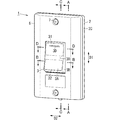
操作部3は、図1〜図3、及び図10に示すように、全体として、後面が開放された、へん平な矩形の箱状に形成されている。操作部3は、例えば、合成樹脂材料により形成されている。操作部3は、基体3Aと、基体3Aの周縁縁から後方へ突出する側体3Bと、軸体3Cと、から構成されている。
(2.6) Operation unit As shown in FIGS. 1 to 3 and 10, the operation unit 3 is formed in the shape of a flat rectangular box with an open rear surface as a whole. The operation unit 3 is made of, for example, a synthetic resin material. The operation unit 3 is composed of a base 3A, a side body 3B protruding rearward from the peripheral edge of the base 3A, and a shaft body 3C.
基体3Aは、略矩形板状に形成されていて、主に利用者の指先で押される部位である。基体3Aは、第1面30(一表面)と、第1面30とは反対側の面である第2面33と、を有している。本実施形態では、第1面30は前面に相当し、第2面33は後面に相当する。
The substrate 3A is formed in a substantially rectangular plate shape, and is a portion mainly pressed by the fingertips of the user. The substrate 3A has a first surface 30 (one surface) and a second surface 33 which is a surface opposite to the first surface 30. In the present embodiment, the first surface 30 corresponds to the front surface, and the second surface 33 corresponds to the rear surface.
基体3Aは、第1面30に、第1領域31及び第2領域32を有している(図3参照)。利用者が第1領域31又は第2領域32へ押操作することで、押圧が弾性部材2に与えられ、スイッチ10における接点11(図5及び図6参照)の開閉状態が切り替えられる。また、第1領域31の上部には、図3に示すように、左右方向に細長い突起部3Dが設けられている。利用者は、突起部3Dを目印として、突起部3Dのある第1領域31を押操作することで、スイッチ10の接点11をオン状態に切り替えることができる。なお、突起部3Dの代わりに、スイッチ10のランプカバー121を透過した光がスイッチ装置1の外部に出射されるための、透光性を有した表示用カバーが、基体3Aを貫通する孔に設けられていてもよい。ただし、この場合、弾性部材2は、透光性を有していることが望ましい。
The substrate 3A has a first region 31 and a second region 32 on the first surface 30 (see FIG. 3). When the user pushes into the first region 31 or the second region 32, the pressure is applied to the elastic member 2, and the open / closed state of the contact 11 (see FIGS. 5 and 6) in the switch 10 is switched. Further, as shown in FIG. 3, a protrusion 3D elongated in the left-right direction is provided on the upper portion of the first region 31. The user can switch the contact 11 of the switch 10 to the ON state by pressing and operating the first region 31 where the protrusion 3D is located, using the protrusion 3D as a mark. Instead of the protrusion 3D, a translucent display cover for emitting light transmitted through the lamp cover 121 of the switch 10 to the outside of the switch device 1 is provided in a hole penetrating the substrate 3A. It may be provided. However, in this case, it is desirable that the elastic member 2 has translucency.
また、基体3Aは、図2及び図9Bに示すように、第2面33において、4個の押子部35と、2個の補強リブ36とを有している。各押子部35は、第1方向D1及び第2方向D2に直交する方向、すなわち、後方向に沿って突出しており、弾性部材2の接触部20と接触することで操作部3からの押圧を弾性部材2に与える。また、各押子部35は、図5〜図7に示すように、第2方向D2(左右方向)から見て、弾性部材2に近づくほど、第1方向D1(上下方向)における長さ寸法が小さくなるように構成されている。操作部3が押子部35を有していることで、押圧を弾性部材2により確実に与えることができる。
Further, as shown in FIGS. 2 and 9B, the substrate 3A has four pusher portions 35 and two reinforcing ribs 36 on the second surface 33. Each pusher portion 35 projects in a direction orthogonal to the first direction D1 and the second direction D2, that is, in the rear direction, and is pressed by the operation portion 3 by coming into contact with the contact portion 20 of the elastic member 2. Is given to the elastic member 2. Further, as shown in FIGS. 5 to 7, each pusher portion 35 has a length dimension in the first direction D1 (vertical direction) as it approaches the elastic member 2 when viewed from the second direction D2 (horizontal direction). Is configured to be small. Since the operating portion 3 has the pusher portion 35, the pressing can be reliably applied by the elastic member 2.
各押子部35は、更に、その角部分350がアール形状となるように形成されている。本実施形態の各押子部35は、図5〜図7に示すように、例えば、第2方向D2(左右方向)から見て、全体として逆台形の板状に形成されている。押子部35の角部分350がアール形状に形成されていることで、操作部3は、弾性部材2の接触部20に対して滑らかに接触する。したがって、利用者に与える操作感を更に良くすることができる。
Each pusher portion 35 is further formed so that its corner portion 350 has a rounded shape. As shown in FIGS. 5 to 7, each pusher portion 35 of the present embodiment is formed in an inverted trapezoidal plate shape as a whole when viewed from, for example, the second direction D2 (left-right direction). Since the corner portion 350 of the pusher portion 35 is formed in a rounded shape, the operation portion 3 smoothly contacts the contact portion 20 of the elastic member 2. Therefore, the operability given to the user can be further improved.
4個の押子部35のうち、一方の対を成す2個の押子部35が、第2面33の上端寄りの領域において、第2方向D2(左右方向)に沿って並んで配置されている。また、他方の対を成す2個の押子部35が、第2面33の下端寄りの領域において、第2方向D2(左右方向)に沿って並んで配置されている。
Of the four pusher portions 35, two pusher portions 35 forming one pair are arranged side by side along the second direction D2 (left-right direction) in the region near the upper end of the second surface 33. ing. Further, the other pair of two pusher portions 35 are arranged side by side along the second direction D2 (left-right direction) in the region near the lower end of the second surface 33.
各補強リブ36は、接触部20に押し付けられる押子部35の破損を防ぐための補強用の部位である。各補強リブ36は、凸状となって形成されており、第2方向D2(左右方向)に沿って延びている。2個の補強リブ36のうち、一方の補強リブ36が、上端寄りの2個の押子部35を連結する。また、他方の補強リブ36が、下端寄りの2個の押子部35を連結する。本実施形態の各補強リブ36は、図10に示すように、対応する一対の補強リブ36を左右方向に貫通するように側体3Bの右壁302から左壁303まで形成されている。
Each reinforcing rib 36 is a reinforcing portion for preventing damage to the pusher portion 35 pressed against the contact portion 20. Each reinforcing rib 36 is formed in a convex shape and extends along the second direction D2 (left-right direction). Of the two reinforcing ribs 36, one reinforcing rib 36 connects the two pusher portions 35 near the upper end. Further, the other reinforcing rib 36 connects the two pusher portions 35 near the lower end. As shown in FIG. 10, each reinforcing rib 36 of the present embodiment is formed from the right wall 302 to the left wall 303 of the side body 3B so as to penetrate the corresponding pair of reinforcing ribs 36 in the left-right direction.
側体3Bは、図10に示すように、前後方向から見て、上壁300、下壁301、右壁302及び左壁303で構成された矩形の枠状に形成されている。右壁302及び左壁303の後面には、上下方向の中央に、後方へ突出する略台形状の突起304,305が、それぞれ設けられており、更に、その突起304,305の先端には、軸体3Cを構成する軸部37及び軸部38が、それぞれ設けられている。軸部37は、突起304の先端から右方に突き出るように形成され、軸部38は、突起305の先端から左方に突き出るように形成されている。軸部37及び軸部38の軸心は、左右方向に沿っていて、互いに一致する。操作部3は、軸体3Cの軸部37及び軸部38がカバー体6の軸受け64,65にそれぞれ軸支されて、カバー体6に対して揺動可能となっている。なお、左右方向における軸部37の寸法は、軸部37の寸法よりもやや長い。
As shown in FIG. 10, the side body 3B is formed in a rectangular frame shape composed of an upper wall 300, a lower wall 301, a right wall 302, and a left wall 303 when viewed from the front-rear direction. On the rear surfaces of the right wall 302 and the left wall 303, substantially trapezoidal protrusions 304 and 305 projecting rearward are provided in the center in the vertical direction, respectively, and further, the tips of the protrusions 304 and 305 are provided. A shaft portion 37 and a shaft portion 38 constituting the shaft body 3C are provided, respectively. The shaft portion 37 is formed so as to protrude to the right from the tip of the protrusion 304, and the shaft portion 38 is formed so as to protrude to the left from the tip of the protrusion 305. The axes of the shaft portion 37 and the shaft portion 38 are aligned with each other along the left-right direction. In the operation unit 3, the shaft portion 37 and the shaft portion 38 of the shaft body 3C are pivotally supported by the bearings 64 and 65 of the cover body 6, respectively, and can swing with respect to the cover body 6. The size of the shaft portion 37 in the left-right direction is slightly longer than the size of the shaft portion 37.
ところで、ハンドル12の一面120(前面)は、第2方向D2から見て、操作部3から離れる方向(後方)に円弧状に凹んでいる。ここで、本実施形態の操作部3の基体3Aは、図5及び図6に示すように、第2方向D2から見て、全体的にハンドル12に近づく方向に円弧状に凹んでいる。特に、操作部3の第2面33(後面)は、第2方向D2から見て、ハンドル12の円弧状の一面120と同心円状に凹んでいる。そのため、例えば第2面33が平坦な面である場合と比べて、操作部3がハンドル12の一面120に対して弾性部材2越しに接触する際に、第2面33と一面120が成す角度が小さい状態で接触することができる。要するに、操作部3がハンドル12の一面120に対して弾性部材2越しに滑らかに接触することができる。したがって、利用者に与える操作感を更に良くすることができる。
By the way, one surface 120 (front surface) of the handle 12 is recessed in an arc shape in a direction away from the operation unit 3 (rear) when viewed from the second direction D2. Here, as shown in FIGS. 5 and 6, the substrate 3A of the operation unit 3 of the present embodiment is recessed in an arc shape as a whole in the direction approaching the handle 12 when viewed from the second direction D2. In particular, the second surface 33 (rear surface) of the operation unit 3 is recessed concentrically with the arcuate one surface 120 of the handle 12 when viewed from the second direction D2. Therefore, for example, as compared with the case where the second surface 33 is a flat surface, the angle formed by the second surface 33 and the one surface 120 when the operation unit 3 comes into contact with the one surface 120 of the handle 12 through the elastic member 2. Can be contacted in a small state. In short, the operation unit 3 can smoothly contact the one surface 120 of the handle 12 through the elastic member 2. Therefore, the operability given to the user can be further improved.
(2.7)カバー体
カバー体6は、図1〜図3に示すように、全体として上下方向に長尺で、後面が開放されたへん平な矩形の箱状に形成されている。カバー体6は、例えば、合成樹脂材料により形成されている。上下方向及び左右方向におけるカバー体6の寸法は、弾性部材2の寸法とおおむね同じである。言い換えると、弾性部材2がカバー体6に組み付けられた状態において、図3に示すように、互いの外周側面がおおむね面一となるように、寸法関係が規定されている。なお、カバー体6の前面は、左右両縁付近では、後方へ緩やかに傾斜している。
(2.7) Cover body As shown in FIGS. 1 to 3, the cover body 6 is formed in a flat rectangular box shape that is long in the vertical direction as a whole and has an open rear surface. The cover body 6 is made of, for example, a synthetic resin material. The dimensions of the cover body 6 in the vertical direction and the horizontal direction are substantially the same as the dimensions of the elastic member 2. In other words, when the elastic member 2 is assembled to the cover body 6, the dimensional relationship is defined so that the outer peripheral side surfaces of the elastic member 2 are substantially flush with each other as shown in FIG. The front surface of the cover body 6 is gently inclined rearward in the vicinity of both the left and right edges.
カバー体6は、上下方向及び左右方向の中央に、操作部3を露出するための露出窓61を有している。露出窓61は、カバー体6をその厚み方向に沿って矩形状に貫通している。また、カバー体6は、その前面の上縁近傍及び下縁近傍における左右方向の中央に、それぞれ、ねじ7の頭部が収まるねじ穴66を有している。また、各ねじ穴66の底面には、ねじ7のねじ部が通るための貫通孔が設けられていて、当該貫通孔は、カバー体6の後面に設けられている第2ボス63(図2参照)を前後方向に貫いている。
The cover body 6 has an exposure window 61 for exposing the operation unit 3 at the center in the vertical direction and the horizontal direction. The exposed window 61 penetrates the cover body 6 in a rectangular shape along the thickness direction thereof. Further, the cover body 6 has screw holes 66 in which the head of the screw 7 is accommodated, respectively, at the center in the left-right direction in the vicinity of the upper edge and the vicinity of the lower edge of the front surface thereof. Further, the bottom surface of each screw hole 66 is provided with a through hole through which the screw portion of the screw 7 passes, and the through hole is a second boss 63 provided on the rear surface of the cover body 6 (FIG. 2). (See) in the front-back direction.
カバー体6は、図2に示すように、その後面において、操作部3の軸体3Cを軸支するための軸受け64,65を有している。軸受け64,65は、露出窓61の左右の縁部分における上下方向の中央に、それぞれ設けられている。軸受け64,65の各々は、略半円筒形状に前方へ凹んで形成されている。左右方向における軸受け64,65の寸法は、軸部37,38の長さ寸法に合わせて、規定されている。すなわち、左右方向における軸受け64の寸法は、軸受け65の寸法よりも大きい。
As shown in FIG. 2, the cover body 6 has bearings 64 and 65 for axially supporting the shaft body 3C of the operation unit 3 on the rear surface. The bearings 64 and 65 are provided at the center in the vertical direction at the left and right edge portions of the exposed window 61, respectively. Each of the bearings 64 and 65 is formed by being recessed forward in a substantially semi-cylindrical shape. The dimensions of the bearings 64 and 65 in the left-right direction are defined according to the length dimensions of the shaft portions 37 and 38. That is, the size of the bearing 64 in the left-right direction is larger than the size of the bearing 65.
また、露出窓61の上下の縁部分の各々の近傍には、第1ボス62が設けられている。第1ボス62は、弾性部材2の孔部25を通ったタッピンねじ8がねじ込まれるねじ孔を有している。なお、カバー体6の後面には、第1ボス62,62、第2ボス63,63、及び軸受け64,65の強度を保つための補強用のリブ68が設けられている。
Further, a first boss 62 is provided in the vicinity of each of the upper and lower edge portions of the exposed window 61. The first boss 62 has a screw hole into which the tapping screw 8 that has passed through the hole 25 of the elastic member 2 is screwed. The rear surface of the cover body 6 is provided with reinforcing ribs 68 for maintaining the strength of the first bosses 62, 62, the second bosses 63, 63, and the bearings 64, 65.
また、カバー体6は、その後面における周縁に、弾性部材2の溝部26に嵌め込まれる周縁突起60を有している。なお、周縁突起60は、その下部において、弾性部材2の水抜き溝281,281とそれぞれ対向する位置に、前方に窪んだ凹部67,67を有している。凹部67,67は、水抜き溝281,281とともに、カバー体6と弾性部材2との間に入り込んだ水(例えば雨水)をスイッチ装置1の外部へ排出することができる。
Further, the cover body 6 has a peripheral projection 60 fitted into the groove 26 of the elastic member 2 on the peripheral edge on the rear surface. The peripheral protrusion 60 has recesses 67 and 67 recessed forward at positions facing the drainage grooves 281,281 of the elastic member 2 at the lower portion thereof. The recesses 67 and 67, together with the drainage grooves 281,281, can discharge the water (for example, rainwater) that has entered between the cover body 6 and the elastic member 2 to the outside of the switch device 1.
(2.8)組立手順
以下、製造時におけるスイッチ装置1の組立手順について簡単に説明する。以下の組立手順は、単なる一例であり、特に限定されるものではない。
(2.8) Assembly Procedure The assembly procedure of the switch device 1 at the time of manufacturing will be briefly described below. The following assembly procedure is merely an example and is not particularly limited.
まず、組立作業を行う作業者は、スイッチ10を組立枠5に組み付ける。具体的には、作業者は、組立枠5の挿入口50に対して組立枠5の後からスイッチ10のハンドル12及び第1ブロック13Aの前方部位130を挿入し、一方の取付片52を下側のスリット13Dに差し込む。他方の取付片51は、マイナスドライバー等の工具の先端を差込孔53に差し込んで、挿入口50の上縁部分を下方へかしめることで、上側のスリット13Dに係止し、スイッチ10が組立枠5に固定される。
First, the worker who performs the assembly work assembles the switch 10 to the assembly frame 5. Specifically, the operator inserts the handle 12 of the switch 10 and the front portion 130 of the first block 13A into the insertion port 50 of the assembly frame 5 from behind the assembly frame 5, and lowers one mounting piece 52. Insert it into the slit 13D on the side. The other mounting piece 51 is locked to the upper slit 13D by inserting the tip of a tool such as a flat-blade screwdriver into the insertion hole 53 and crimping the upper edge portion of the insertion port 50 downward, and the switch 10 is engaged. It is fixed to the assembly frame 5.
次に、作業者は、操作部3をカバー体6の後面側から露出窓61に挿入する。この時、操作部3の軸部37を軸受け64に、軸部38を軸受け65に、それぞれ嵌める。この状態で、作業者は、カバー体6の後面を弾性部材2で覆う。この時、弾性部材2の被覆部2Aは、操作部3内に収められ、弾性部材2の溝部26内に、カバー体6の周縁突起60が嵌め込まれる。さらに、作業者は、スイッチ10が組み付けられている組立枠5を、ハンドル12の一面120が弾性部材2の接触部20と対向するように、弾性部材2の後面に配置させる。
Next, the operator inserts the operation unit 3 into the exposed window 61 from the rear surface side of the cover body 6. At this time, the shaft portion 37 of the operation unit 3 is fitted to the bearing 64, and the shaft portion 38 is fitted to the bearing 65. In this state, the operator covers the rear surface of the cover body 6 with the elastic member 2. At this time, the covering portion 2A of the elastic member 2 is housed in the operating portion 3, and the peripheral projection 60 of the cover body 6 is fitted in the groove portion 26 of the elastic member 2. Further, the operator arranges the assembly frame 5 to which the switch 10 is assembled on the rear surface of the elastic member 2 so that the one surface 120 of the handle 12 faces the contact portion 20 of the elastic member 2.
次に、作業者は、2本のタッピンねじ8を、組立枠5の後方から、組立枠5の挿通孔54,54に挿入し、更に、弾性部材2の孔部25,25に挿入して、最後にカバー体6の後面にある第1ボス62,62のねじ孔にねじ込む。その結果、スイッチ10、組立枠5、弾性部材2、及び操作部3が、カバー体6と一体となるように組み付けられる。
Next, the operator inserts the two tapping screws 8 into the insertion holes 54 and 54 of the assembly frame 5 from the rear of the assembly frame 5, and further inserts them into the holes 25 and 25 of the elastic member 2. Finally, the screw is screwed into the screw holes of the first bosses 62 and 62 on the rear surface of the cover body 6. As a result, the switch 10, the assembly frame 5, the elastic member 2, and the operation unit 3 are assembled so as to be integrated with the cover body 6.
そして、作業者は、取付枠4を、弾性部材2の側壁2Cで囲まれた空間内に収まるように、弾性部材2の後方から配置させる。最後に、作業者は、2本のねじ7,7を、カバー体6の前面にあるねじ穴66,66の貫通孔に挿入して、弾性部材2の嵌合孔280,280に通し、取付枠4の段部41,41にあるねじ孔42,42にねじ込む。その結果、スイッチ装置1の組立が完了する。
Then, the operator arranges the mounting frame 4 from the rear of the elastic member 2 so as to fit in the space surrounded by the side wall 2C of the elastic member 2. Finally, the operator inserts the two screws 7 and 7 into the through holes of the screw holes 66 and 66 on the front surface of the cover body 6 and passes them through the fitting holes 280 and 280 of the elastic member 2 for mounting. It is screwed into the screw holes 42, 42 in the step portions 41, 41 of the frame 4. As a result, the assembly of the switch device 1 is completed.
なお、製造時において、スイッチ装置1は、上述のように完全に組み立てられた状態でなくてもよいし、また、ねじによる固定は、仮止め程度に比較的緩い状態であってもよい。例えば、ねじ7,7によって取付枠4を、弾性部材2及びカバー体6等に組み付ける作業は、実際に施工する施工現場で行われてもよい。スイッチ装置1の施工手順の詳細な説明は省略するが、スイッチ装置1を例えば屋外の造営材の表面に施工する際には、取付枠4を先にスイッチボックス等にねじ止めして、スイッチ10に対する配線回りの接続作業を行う。その後に、ねじ7,7によって、弾性部材2及びカバー体6等を、取付枠4にねじ止めしてもよい。
At the time of manufacture, the switch device 1 may not be in a completely assembled state as described above, and the fixing with screws may be in a relatively loose state to the extent of temporary fixing. For example, the work of assembling the mounting frame 4 to the elastic member 2 and the cover body 6 with the screws 7 and 7 may be performed at the actual construction site. Although detailed description of the construction procedure of the switch device 1 is omitted, when the switch device 1 is constructed on the surface of an outdoor construction material, for example, the mounting frame 4 is first screwed to a switch box or the like, and the switch 10 Perform connection work around the wiring for. After that, the elastic member 2, the cover body 6, and the like may be screwed to the mounting frame 4 with screws 7 and 7.
(3)操作部及び弾性部材の動作説明
以下、利用者がスイッチ装置1(の操作部3)を押操作する際における、操作部3及び弾性部材2の動作について説明する。ここでは、利用者が操作部3を押操作する前まで、操作部3の第2領域32が後方に押し込まれていて、スイッチ10の接点11がオフ状態である(図6参照)ことを想定する。また、ここでは、スイッチ10は、電源と照明負荷とを電気的に接続する給電路の途中に接続されていることを想定する。要するに、利用者が操作部3を押操作する前まで照明負荷が消灯状態にあったとする。
(3) Description of Operation of Operation Unit and Elastic Member The operation of the operation unit 3 and the elastic member 2 when the user presses the switch device 1 (operation unit 3) will be described below. Here, it is assumed that the second region 32 of the operation unit 3 is pushed backward and the contact 11 of the switch 10 is in the off state until the user presses the operation unit 3 (see FIG. 6). To do. Further, here, it is assumed that the switch 10 is connected in the middle of the power supply path that electrically connects the power supply and the lighting load. In short, it is assumed that the lighting load has been turned off before the user presses the operation unit 3.
利用者は、例えば、消灯状態にある照明負荷を点灯させるために、スイッチ装置1の操作部3を操作する。すなわち、利用者は、前方に突き出ている操作部3の第1領域31を後方へ押す。操作部3は、軸体3Cを中心に搖動し、第1領域31が後方へ下がり、第2領域32が前方へ突き出る。この時、図11Aに示すように、操作部3は、第1領域31とは反対側の後面にある一対の押子部35,35が、弾性部材2の接触部20に当たる。そして、接触部20は、押子部35が当たる上端部位が弾性変形により後方へ凹まされて、スイッチ10のハンドル12の上端部周辺に接触する。その結果、操作部3からの押圧が弾性部材2超しにハンドル12に伝達され、ハンドル12は、接点11がオフ状態からオン状態に切り替わるように搖動する。
The user operates the operation unit 3 of the switch device 1, for example, in order to turn on the lighting load in the extinguished state. That is, the user pushes the first area 31 of the operation unit 3 protruding forward to the rear. The operation unit 3 swings around the shaft body 3C, the first region 31 descends rearward, and the second region 32 protrudes forward. At this time, as shown in FIG. 11A, in the operation unit 3, a pair of pusher portions 35, 35 on the rear surface opposite to the first region 31 hits the contact portion 20 of the elastic member 2. Then, the upper end portion of the contact portion 20 to which the pusher portion 35 hits is recessed rearward due to elastic deformation, and comes into contact with the vicinity of the upper end portion of the handle 12 of the switch 10. As a result, the pressure from the operation unit 3 is transmitted to the handle 12 over the elastic member 2, and the handle 12 swings so that the contact 11 switches from the off state to the on state.
ここで、本実施形態の弾性部材2では、図11A及び11Bに示すように、第1連結部23の厚みW1が第2連結部24の厚みW2よりも小さいことに起因して、第1連結部23は、第2連結部24よりも可撓性が大きい。したがって、操作部3の押子部35,35からの押圧によって接触部20の上端部位が弾性変形により後方へ凹まされたときに、第1連結部23が第2連結部24に比べて大きく撓む。つまり、操作部3から弾性部材2が受ける応力のうち、ハンドル12を押すための力以外の余分な力を、第2連結部24よりも、第1連結部23へ逃がすことになる。
Here, in the elastic member 2 of the present embodiment, as shown in FIGS. 11A and 11B, the thickness W1 of the first connecting portion 23 is smaller than the thickness W2 of the second connecting portion 24, so that the first connecting portion 2 is connected. The portion 23 is more flexible than the second connecting portion 24. Therefore, when the upper end portion of the contact portion 20 is recessed rearward due to elastic deformation due to the pressing from the pusher portions 35, 35 of the operation portion 3, the first connecting portion 23 is greatly bent as compared with the second connecting portion 24. Mmm. That is, of the stress received by the elastic member 2 from the operating portion 3, an extra force other than the force for pushing the handle 12 is released to the first connecting portion 23 rather than the second connecting portion 24.
したがって、操作部3を操作する利用者にとっては、接触部20の周囲にある第1連結部23及び第2連結部24が、略均一に押し潰れる(ひしゃげる)場合に比べて、より良い操作感が得られる。特に、利用者に対して、スイッチ10のオン/オフを切り替えたと認識できるような操作感(例えばカチッといった感触)を与えることができる。
Therefore, for the user who operates the operation unit 3, the operation is better than the case where the first connecting portion 23 and the second connecting portion 24 around the contact portion 20 are crushed (squashed) substantially uniformly. You can get a feeling. In particular, it is possible to give the user an operation feeling (for example, a click feeling) that can be recognized as switching the switch 10 on / off.
また、各第1連結部23の径R1(図11A参照)が各第2連結部24の径R2(図8参照)よりも大きくなるように、互いの寸法関係が規定されている。したがって、第2連結部24よりも可撓性が大きい第1連結部23を、容易に提供することができる。
Further, the dimensional relationship with each other is defined so that the diameter R1 (see FIG. 11A) of each first connecting portion 23 is larger than the diameter R2 (see FIG. 8) of each second connecting portion 24. Therefore, the first connecting portion 23, which is more flexible than the second connecting portion 24, can be easily provided.
また、利用者が、今度は逆に、前方に突き出ている操作部3の第2領域32を後方へ押すと、操作部3は、軸体3Cを中心に搖動し、第2領域32が後方へ下がり、第1領域31が前方へ突き出る。この時、弾性部材2の接触部20の上端部位を押し下げていた押子部35も、弾性部材2から離れる方向(前方)へ移動するため、接触部20の当該上端部位が弾性復帰して、元の状態に戻る(図6参照)。この時の弾性復帰についても、第2連結部24が第1連結部23よりも撓み難いため、第1連結部23及び第2連結部24が略均一に押し潰れている場合に比べて、接触部20を容易に元の状態へ復帰させることができる。
Further, when the user pushes the second area 32 of the operation unit 3 protruding forward this time to the rear, the operation unit 3 swings around the shaft body 3C, and the second area 32 moves backward. The first region 31 protrudes forward. At this time, the pusher portion 35, which has pushed down the upper end portion of the contact portion 20 of the elastic member 2, also moves in the direction away from the elastic member 2 (forward), so that the upper end portion of the contact portion 20 is elastically restored. It returns to the original state (see FIG. 6). Regarding the elastic recovery at this time, since the second connecting portion 24 is less likely to bend than the first connecting portion 23, the contact is made as compared with the case where the first connecting portion 23 and the second connecting portion 24 are crushed substantially uniformly. The unit 20 can be easily returned to the original state.
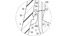
ところで、操作部3の第1領域31及び第2領域32のうち一方が後方へ退き、他方が前方へ突き出た状態にあるとき、図7に示すように、当該他方の領域の反対側の面にある押子部35と、接触部20とには隙間(第1の隙間)が有ることが好ましい。図7は、図5中の点線の円で囲まれた部位の拡大図である。また、接触部20と、前方へ突き出た状態にあるハンドル12の端部(図示例では下端部)とにも隙間(第2の隙間)が有ることが好ましい。なお、この図示例では、上記一方の領域は第1領域31であり、上記他方の領域は第2領域32である。
By the way, when one of the first region 31 and the second region 32 of the operation unit 3 retreats backward and the other protrudes forward, as shown in FIG. 7, the surface on the opposite side of the other region. It is preferable that there is a gap (first gap) between the pusher portion 35 and the contact portion 20. FIG. 7 is an enlarged view of a portion surrounded by a dotted circle in FIG. Further, it is preferable that there is a gap (second gap) between the contact portion 20 and the end portion (lower end portion in the illustrated example) of the handle 12 protruding forward. In this illustrated example, the one region is the first region 31, and the other region is the second region 32.
ここで、上記の第1の隙間は、比較的小さいことが望ましい。第1の隙間の前後方向における(最短)距離L1(図7参照)は、例えば、弾性部材2の接触部20の厚みよりも小さいことが好ましい。本実施形態では、一例として、接触部20の厚みが1mmであり、距離L1が0.2mmである。
Here, it is desirable that the first gap is relatively small. The (shortest) distance L1 (see FIG. 7) in the front-rear direction of the first gap is preferably smaller than, for example, the thickness of the contact portion 20 of the elastic member 2. In the present embodiment, as an example, the thickness of the contact portion 20 is 1 mm, and the distance L1 is 0.2 mm.
同様に、上記の第2の隙間は、比較的小さいことが望ましい。第2の隙間の前後方向における(最短)距離L2(図7参照)は、例えば、距離L1と略等しく、弾性部材2の接触部20の厚みよりも小さいことが好ましい。本実施形態では、一例として、距離L2は、0.2mmである。
Similarly, it is desirable that the second gap is relatively small. The (shortest) distance L2 (see FIG. 7) in the front-rear direction of the second gap is preferably, for example, substantially equal to the distance L1 and smaller than the thickness of the contact portion 20 of the elastic member 2. In the present embodiment, as an example, the distance L2 is 0.2 mm.
なお、図7の状態とは逆に、第1領域31が前方へ突き出て、第2領域32が後方へ退いた状態にあるときも、第1領域31の反対側の後面にある押子部35から接触部20までの(最短)距離L1は、一例として0.2mmである。同様に、接触部20から前方へ突き出た状態にあるハンドル12の上端部までの(最短)距離L2は、一例として0.2mmである。
Contrary to the state of FIG. 7, even when the first region 31 protrudes forward and the second region 32 retreats backward, the pusher portion on the rear surface opposite to the first region 31 The (shortest) distance L1 from 35 to the contact portion 20 is 0.2 mm as an example. Similarly, the (shortest) distance L2 from the contact portion 20 to the upper end portion of the handle 12 protruding forward is 0.2 mm as an example.
このように、操作部3、弾性部材2、及びハンドル12間の距離が設定されていることで、操作感の向上を、更に図ることができる。特に、利用者に対して、スイッチ10のオン/オフを切り替えたと認識できるような操作感(例えばカチッといった感触)を、更により良く与えることができる。
By setting the distance between the operation unit 3, the elastic member 2, and the handle 12 in this way, it is possible to further improve the operability. In particular, it is possible to give the user an even better operational feeling (for example, a click feeling) that allows the user to recognize that the switch 10 has been turned on / off.
(4)変形例
以下に、いくつかの変形例について列記する。以下では上述した実施形態を「基本例」と呼ぶ。
(4) Modification examples Below, some modification examples are listed. Hereinafter, the above-described embodiment will be referred to as a “basic example”.
基本例では、第1連結部23及び第2連結部24の両方がアール形状に形成されているが、第1連結部23のみがアール形状に形成されていてもよい。また、少なくとも、第1連結部23が第2連結部24よりも可撓性が大きければ、第1連結部23及び第2連結部24の両方が、アール形状ではなく、平坦な傾斜面を有するように構成されていてもよいし、あるいは、階段状に形成されていてもよい。
In the basic example, both the first connecting portion 23 and the second connecting portion 24 are formed in a rounded shape, but only the first connecting portion 23 may be formed in a rounded shape. Further, if at least the first connecting portion 23 is more flexible than the second connecting portion 24, both the first connecting portion 23 and the second connecting portion 24 have a flat inclined surface instead of a rounded shape. It may be configured as such, or it may be formed in a staircase pattern.
基本例では、スイッチ装置1がスイッチ10を1個だけ備えているが、スイッチ10を複数個備えていてもよい。この場合、スイッチ装置1は、操作部3を、スイッチ10と同じ数だけ備え、同様に、弾性部材2の被覆部2Aを、スイッチ10と同じ数だけ備えてもよい。
In the basic example, the switch device 1 includes only one switch 10, but a plurality of switches 10 may be provided. In this case, the switch device 1 may include the same number of operation units 3 as the switch 10, and may similarly include the same number of covering portions 2A of the elastic member 2 as the switch 10.
基本例では、操作部3が押子部35を4個有しているが、押子部35の数は特に限定されない。また、押子部35は、操作部3にとって必須の構成要素ではなく、設けられていなくてもよい。ただし、押子部35が設けられている方が、押子部35を通じて、弾性部材2の接触部20に対してより確実に押圧を与えることができる。
In the basic example, the operation unit 3 has four pusher portions 35, but the number of pusher portions 35 is not particularly limited. Further, the pusher portion 35 is not an essential component for the operation portion 3, and may not be provided. However, when the pusher portion 35 is provided, the pressing portion 20 of the elastic member 2 can be pressed more reliably through the pusher portion 35.
基本例では、弾性部材2が軟質の塩化ビニルによって形成されているが、材料は、特に限定されるものではない。弾性部材2は、例えばエラストマ等のゴム材によって形成されていてもよい。ただし、軟質の塩化ビニルを材料として用いて射出成型によって形成する方が、より容易に、第1連結部23の厚みW1を第2連結部24の厚みW2よりも小さくすることができる。
In the basic example, the elastic member 2 is formed of soft vinyl chloride, but the material is not particularly limited. The elastic member 2 may be formed of a rubber material such as an elastomer. However, it is more easily formed by injection molding using soft vinyl chloride as a material, so that the thickness W1 of the first connecting portion 23 can be made smaller than the thickness W2 of the second connecting portion 24.
(5)利点
以上説明したように、第1の態様に係る配線スイッチ構造は、弾性部材2と、操作部3と、を備える。弾性部材2は、スイッチ10のハンドル12を覆い、押圧を受けると弾性変形してハンドル12を搖動させる。操作部3は、一表面(第1面30)に第1領域31及び第2領域32を有し、第1領域31又は第2領域32への押操作に応じて上記押圧を弾性部材2に与えてスイッチ10における接点11の開閉状態を切り替える。弾性部材2は、接触部20と、第1側部21と、第2側部22と、第1連結部23と、第2連結部24と、を有している。接触部20は、上記押圧を受けてハンドル12と接触する。第1側部21は、第1領域31と第2領域32とが並ぶ第1方向D1におけるハンドル12の両端部の少なくとも一方と対向する。第2側部22は、操作部3の一表面(第1面30)の前方から見て、第1方向D1と直交する第2方向D2におけるハンドル12の両端部の少なくとも一方と対向する。第1連結部23は、接触部20と第1側部21とを連結する。第2連結部24は、接触部20と第2側部22とを連結する。第1連結部23は、第2連結部24よりも可撓性が大きい。第1の態様によれば、操作感の向上を図ることができる。
(5) Advantages As described above, the wiring switch structure according to the first aspect includes an elastic member 2 and an operation unit 3. The elastic member 2 covers the handle 12 of the switch 10 and elastically deforms when pressed to cause the handle 12 to oscillate. The operation unit 3 has a first region 31 and a second region 32 on one surface (first surface 30), and the elastic member 2 is pressed in response to a pressing operation on the first region 31 or the second region 32. Then, the open / closed state of the contact 11 in the switch 10 is switched. The elastic member 2 has a contact portion 20, a first side portion 21, a second side portion 22, a first connecting portion 23, and a second connecting portion 24. The contact portion 20 receives the above pressure and comes into contact with the handle 12. The first side portion 21 faces at least one of both end portions of the handle 12 in the first direction D1 in which the first region 31 and the second region 32 are aligned. The second side portion 22 faces at least one of both ends of the handle 12 in the second direction D2 orthogonal to the first direction D1 when viewed from the front of one surface (first surface 30) of the operation portion 3. The first connecting portion 23 connects the contact portion 20 and the first side portion 21. The second connecting portion 24 connects the contact portion 20 and the second side portion 22. The first connecting portion 23 is more flexible than the second connecting portion 24. According to the first aspect, it is possible to improve the operability.
第2の態様に係る配線スイッチ構造に関して、第1の態様において、弾性部材2は、薄膜状に形成されていることが好ましい。第1連結部23の厚みW1は、第2連結部24の厚みW2よりも小さいことが好ましい。第2の態様によれば、第2連結部24よりも可撓性が大きい第1連結部23を容易に提供することができる。
Regarding the wiring switch structure according to the second aspect, in the first aspect, the elastic member 2 is preferably formed in a thin film shape. The thickness W1 of the first connecting portion 23 is preferably smaller than the thickness W2 of the second connecting portion 24. According to the second aspect, the first connecting portion 23 having a greater flexibility than the second connecting portion 24 can be easily provided.
第3の態様に係る配線スイッチ構造に関して、第1又は第2の態様において、第1連結部23は、アール形状に形成されていることが好ましい。第3の態様によれば、第1連結部23の可撓性をより大きくすることができる。
Regarding the wiring switch structure according to the third aspect, in the first or second aspect, the first connecting portion 23 is preferably formed in a rounded shape. According to the third aspect, the flexibility of the first connecting portion 23 can be increased.
第4の態様に係る配線スイッチ構造に関して、第3の態様において、更に、第2連結部24は、アール形状に形成されていて、第1連結部23の径R1は、第2連結部24の径R2よりも大きいことが好ましい。第4の態様によれば、第2連結部24よりも可撓性が大きい第1連結部23を容易に提供することができる。
Regarding the wiring switch structure according to the fourth aspect, in the third aspect, the second connecting portion 24 is further formed in a rounded shape, and the diameter R1 of the first connecting portion 23 is the diameter R1 of the second connecting portion 24. It is preferably larger than the diameter R2. According to the fourth aspect, the first connecting portion 23 having a greater flexibility than the second connecting portion 24 can be easily provided.
第5の態様に係る配線スイッチ構造に関して、第1〜第4の態様のいずれか1つにおいて、ハンドル12は、接触部20と接触する一面120を有し、一面120は、第2方向D2から見て、操作部3から離れる方向に円弧状に凹んでいることが好ましい。また、操作部3の一表面(第1面30)とは反対側の面(第2面33)は、第2方向D2から見て、ハンドル12の円弧状の一面120と同心円状に凹んでいることが好ましい。第5の態様によれば、例えば操作部3の第2面33が平坦な面である場合と比べて、操作部3がハンドル12の一面120に対して弾性部材2越しに接触する際に、第2面33と一面120が成す角度が小さい状態で接触することができる。要するに、操作部3がハンドル12の一面120に対して弾性部材2越しに滑らかに接触することができる。したがって、利用者に与える操作感を更に良くすることができる。
Regarding the wiring switch structure according to the fifth aspect, in any one of the first to fourth aspects, the handle 12 has one surface 120 in contact with the contact portion 20, and the one surface 120 is from the second direction D2. As seen, it is preferable that the portion is recessed in an arc shape in the direction away from the operation unit 3. Further, the surface (second surface 33) opposite to one surface (first surface 30) of the operation unit 3 is recessed concentrically with the arc-shaped one surface 120 of the handle 12 when viewed from the second direction D2. It is preferable to have. According to the fifth aspect, for example, as compared with the case where the second surface 33 of the operation unit 3 is a flat surface, when the operation unit 3 comes into contact with the one surface 120 of the handle 12 through the elastic member 2. The second surface 33 and the first surface 120 can be brought into contact with each other in a small angle. In short, the operation unit 3 can smoothly contact the one surface 120 of the handle 12 through the elastic member 2. Therefore, the operability given to the user can be further improved.
第6の態様に係る配線スイッチ構造に関して、第1〜第5の態様のいずれか1つにおいて、操作部3は、一表面(第1面30)とは反対側の面(第2面33)において、押子部35を有していることが好ましい。押子部35は、第1方向D1及び第2方向D2に直交する方向に突出し、接触部20と接触して上記押圧を与える。押子部35は、第2方向D2から見て、弾性部材2に近づくほど、第1方向D1における長さ寸法が小さくなっており、押子部35の角部分350は、アール形状に形成されていることが好ましい。第6の態様によれば、押子部35を通じて、弾性部材2の接触部20に対してより確実に上記押圧を与えることができる。また、押子部35の角部分350は、アール形状に形成されているため、操作部3は、弾性部材2の接触部20に対して滑らかに接触する。したがって、利用者に与える操作感を更に良くすることができる。
Regarding the wiring switch structure according to the sixth aspect, in any one of the first to fifth aspects, the operation unit 3 has a surface (second surface 33) opposite to one surface (first surface 30). It is preferable to have the pusher portion 35. The pusher portion 35 projects in a direction orthogonal to the first direction D1 and the second direction D2, and comes into contact with the contact portion 20 to apply the above-mentioned pressing. When the pusher portion 35 is viewed from the second direction D2, the closer to the elastic member 2, the smaller the length dimension in the first direction D1, and the corner portion 350 of the pusher portion 35 is formed in a rounded shape. Is preferable. According to the sixth aspect, the pressing can be more reliably applied to the contact portion 20 of the elastic member 2 through the pusher portion 35. Further, since the corner portion 350 of the pusher portion 35 is formed in a rounded shape, the operation portion 3 smoothly contacts the contact portion 20 of the elastic member 2. Therefore, the operability given to the user can be further improved.
第7の態様に係る配線スイッチ構造に関して、第6の態様において、操作部3は、押子部35を複数備え、複数の押子部35は、第2方向D2に沿って並んで配置されることが好ましい。操作部3は、一表面(第1面30)とは反対側の面(第2面33)において、第2方向D2に沿って延びていて、かつ、複数の押子部35を連結する、凸状の補強リブ36を、更に有していることが好ましい。第7の態様によれば、操作部3が弾性部材2の接触部20と接触する際に、弾性部材2から受ける抗力が複数の押子部35によって分散される。したがって、利用者に与える操作感を更に良くすることができる。また、補強リブ36により、複数の押子部35の強度の向上を図ることができる。
Regarding the wiring switch structure according to the seventh aspect, in the sixth aspect, the operation unit 3 includes a plurality of pusher portions 35, and the plurality of pusher portions 35 are arranged side by side along the second direction D2. Is preferable. The operation unit 3 extends along the second direction D2 on a surface (second surface 33) opposite to one surface (first surface 30) and connects a plurality of pusher portions 35. It is preferable to further have the convex reinforcing ribs 36. According to the seventh aspect, when the operating portion 3 comes into contact with the contact portion 20 of the elastic member 2, the drag force received from the elastic member 2 is dispersed by the plurality of pusher portions 35. Therefore, the operability given to the user can be further improved. Further, the reinforcing ribs 36 can improve the strength of the plurality of pusher portions 35.
第8の態様に係る配線スイッチ構造に関して、第1〜第7の態様のいずれか1つにおいて、スイッチ10は、シーソー型スイッチであることが好ましい。第8の態様によれば、シーソー型スイッチであるスイッチ10に適用することで、利用者に与える操作感を更に良くすることができる。
Regarding the wiring switch structure according to the eighth aspect, in any one of the first to seventh aspects, the switch 10 is preferably a seesaw type switch. According to the eighth aspect, by applying it to the switch 10 which is a seesaw type switch, the operation feeling given to the user can be further improved.
第9の態様に係るスイッチ装置1は、第1〜第8の態様のいずれか1つにおける配線スイッチ構造と、スイッチ10と、を備える。第9の態様によれば、操作感の向上を図ることができるスイッチ装置1を提供することができる。
The switch device 1 according to the ninth aspect includes the wiring switch structure in any one of the first to eighth aspects, and the switch 10. According to the ninth aspect, it is possible to provide the switch device 1 capable of improving the operability.