JP6830233B2 - Equipment for plant cultivation - Google Patents
Equipment for plant cultivation Download PDFInfo
- Publication number
- JP6830233B2 JP6830233B2 JP2016187054A JP2016187054A JP6830233B2 JP 6830233 B2 JP6830233 B2 JP 6830233B2 JP 2016187054 A JP2016187054 A JP 2016187054A JP 2016187054 A JP2016187054 A JP 2016187054A JP 6830233 B2 JP6830233 B2 JP 6830233B2
- Authority
- JP
- Japan
- Prior art keywords
- cultivation
- plant
- chamber box
- cultivation space
- space
- Prior art date
- Legal status (The legal status is an assumption and is not a legal conclusion. Google has not performed a legal analysis and makes no representation as to the accuracy of the status listed.)
- Expired - Fee Related
Links
Images

Classifications
-
- Y—GENERAL TAGGING OF NEW TECHNOLOGICAL DEVELOPMENTS; GENERAL TAGGING OF CROSS-SECTIONAL TECHNOLOGIES SPANNING OVER SEVERAL SECTIONS OF THE IPC; TECHNICAL SUBJECTS COVERED BY FORMER USPC CROSS-REFERENCE ART COLLECTIONS [XRACs] AND DIGESTS
- Y02—TECHNOLOGIES OR APPLICATIONS FOR MITIGATION OR ADAPTATION AGAINST CLIMATE CHANGE
- Y02A—TECHNOLOGIES FOR ADAPTATION TO CLIMATE CHANGE
- Y02A40/00—Adaptation technologies in agriculture, forestry, livestock or agroalimentary production
- Y02A40/10—Adaptation technologies in agriculture, forestry, livestock or agroalimentary production in agriculture
- Y02A40/25—Greenhouse technology, e.g. cooling systems therefor
Landscapes
- Cultivation Of Plants (AREA)
- Greenhouses (AREA)
Description
本発明は、植物工場などの屋内で植物を効率的に栽培することのできる植物栽培用装置に関するものであり、より具体的には、外部環境の影響を受けることなく植物を栽培することのできる植物栽培用装置に関するものである。 The present invention relates to a plant cultivation device capable of efficiently cultivating a plant indoors such as a plant factory, and more specifically, the plant can be cultivated without being affected by the external environment. It relates to a device for plant cultivation.
植物を植物工場などの屋内で栽培する植物栽培装置が提案されている。植物栽培装置は、空調手段及び照明手段を具え、栽培パレットに植えられた植物に適度な空調と照明を提供することで、外部環境の影響を排除し、好適な栽培条件で植物を栽培するようにしている。 A plant cultivation device for cultivating plants indoors such as a plant factory has been proposed. The plant cultivation device is equipped with air-conditioning means and lighting means, and provides appropriate air-conditioning and lighting to the plants planted on the cultivation pallet to eliminate the influence of the external environment and cultivate the plants under suitable cultivation conditions. I have to.
たとえば、特許文献1では、多段に形成された栽培空間に夫々栽培パレットを配置し、空調手段と各栽培空間をダクトで連結すると共に、各空間の天井面に照明を設置している。 For example, in Patent Document 1, cultivation pallets are arranged in each of the cultivation spaces formed in multiple stages, the air conditioning means and each cultivation space are connected by a duct, and lighting is installed on the ceiling surface of each space.
栽培空間と空調手段とをダクトにより接続した場合、栽培空間の段数を変更するにはダクトを繋ぎ直す必要があり、栽培空間の段数が増加すると配管が複雑になる。また、ダクトの長さや屈曲度合いによって栽培空間毎に供給される気流に差が生じるから、植物に合わせた均質な気流環境を提供することが困難である。 When the cultivation space and the air conditioning means are connected by a duct, it is necessary to reconnect the ducts in order to change the number of stages of the cultivation space, and as the number of stages of the cultivation space increases, the piping becomes complicated. In addition, it is difficult to provide a uniform airflow environment suitable for plants because the airflow supplied to each cultivation space differs depending on the length of the duct and the degree of bending.
さらに、出願人は、植物の生長に合わせて、気流を当てる位置を調整することで、その生長を促進できることを見出し、本発明に至った。 Furthermore, the applicant has found that the growth can be promoted by adjusting the position where the airflow is applied according to the growth of the plant, and has reached the present invention.
本発明の目的は、各栽培空間に均質な気流環境を整え、植物の生長に合わせて気流を当てる位置の調整ができる植物栽培装置を提供することである。 An object of the present invention is to provide a plant cultivation apparatus capable of preparing a homogeneous airflow environment in each cultivation space and adjusting the position of applying the airflow according to the growth of the plant.
上記課題を解決するために、本発明に係る植物栽培装置は、
配風手段と、
前記配風手段に連繋されたチャンバーボックスと、
前記チャンバーボックスに併設され、内部に植物の栽培パレットが配置される1段又は複数段の栽培空間と、
を具えた植物栽培装置であって、
前記チャンバーボックスと前記栽培空間は、1又は複数の開口部が形成されたパネルによって仕切られている。
In order to solve the above problems, the plant cultivation apparatus according to the present invention is used.
Wind distribution means and
A chamber box connected to the air distribution means and
A one-stage or multiple-stage cultivation space that is attached to the chamber box and has a plant cultivation palette inside.
It is a plant cultivation device equipped with
The chamber box and the cultivation space are separated by a panel having one or more openings formed therein.
前記開口部は、前記パネルの幅方向に長く開設されたスリットとすることができる。 The opening can be a slit long in the width direction of the panel.
前記パネルは、前記栽培空間に対して高さ方向に位置調整可能とすることが望ましい。 It is desirable that the panel can be adjusted in height with respect to the cultivation space.
前記チャンバーボックスには、ソックダクトが配設されており、前記配風手段からの気流はソックダクトを通じて導入することが望ましい。 A sock duct is provided in the chamber box, and it is desirable that the airflow from the air distribution means is introduced through the sock duct.
前記栽培空間の天井面には、前記パネルと略平行に風向調整板が突設することができる。 On the ceiling surface of the cultivation space, a wind direction adjusting plate can be provided so as to project substantially parallel to the panel.
本発明の植物栽培装置によれば、配風手段から気流が導入されるチャンバーボックスと、栽培空間の間を開口部の形成されたパネルによって連繋しているから、各栽培空間にダクトを配設する必要はなく、構成を簡素化できる。また、スリットなどの開口部によって直接チャンバーボックスと栽培空間を連通させているから、ダクトの長さや屈曲度合いによって調整の難しかった均質な気流環境を提供できる。 According to the plant cultivation apparatus of the present invention, since the chamber box in which the air flow is introduced from the wind distribution means and the cultivation space are connected by a panel having an opening, a duct is arranged in each cultivation space. There is no need to do this, and the configuration can be simplified. Further, since the chamber box and the cultivation space are directly communicated with each other through an opening such as a slit, it is possible to provide a homogeneous airflow environment that is difficult to adjust depending on the length of the duct and the degree of bending.
栽培空間に対してパネルを高さ調整することで開口部の高さを可変とすることができるから、植物の生長に合わせて気流を当てることができ、その生長を促進することができ、効率的な植物栽培を実現できる。 Since the height of the opening can be made variable by adjusting the height of the panel with respect to the cultivation space, it is possible to apply an air flow according to the growth of the plant, and it is possible to promote the growth and efficiency. Plant cultivation can be realized.
また、チャンバーボックスへの気流の導入を、ソックダクトを通じて行なうことで、チャンバーボックスから開口部を通じて栽培空間に供給される気流の均質化を達成できる。 Further, by introducing the airflow into the chamber box through the sock duct, the homogenization of the airflow supplied from the chamber box to the cultivation space through the opening can be achieved.
さらに、栽培空間の天井面に風向調整板を配置することで、開口部から離れた位置の植物に対しても好適な気流を提供できる。 Further, by arranging the wind direction adjusting plate on the ceiling surface of the cultivation space, it is possible to provide a suitable air flow even for plants located away from the opening.
以下、図面を参照しながら本発明の植物栽培装置10について説明する。
Hereinafter, the
本発明の植物栽培装置10で栽培される植物50は、レタス、せり、糸三つ葉、モロヘイヤ、レッドキャベツ、セルリー、ホウレンソウ、春菊、大葉などを例示できるが、これらに限定されるものではない。
Examples of the
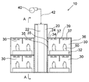
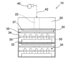
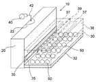
図1乃至図3に示すように、本発明の植物栽培装置10は、電動ファンなどの配風手段40から気流が供給されるチャンバーボックス20と、チャンバーボックス20と連通する栽培空間30を具える。植物栽培装置10は、植物工場などの屋内に設置することができる。
As shown in FIGS. 1 to 3, the
図示の実施形態では、植物栽培装置10は、中央にチャンバーボックス20が配置され、その両側に栽培空間30を夫々2段ずつ併設して構成しているが、栽培空間30の配置は一方のみでもよく、また、その段数も2段に限定されるものではない。さらに、栽培空間30は幅方向(横方向)に複数設けることもできる。この場合、隣り合う栽培空間30どうしの間には仕切りは不要であり、両端の栽培空間30の端側のみを塞ぐ構成とすればよい。但し、各栽培空間30で異なる種類の植物50や生長状態の異なる植物50を栽培する場合には、各栽培空間30どうしの間に仕切りを設けることが望ましい。
In the illustrated embodiment, the
チャンバーボックス20は、配風手段40とダクト42を介して接続されている。チャンバーボックス20は、比較的広い空間であって、配風手段40からの気流を安定させる役割をなす。
The
チャンバーボックス20は、配風手段40からの気流をさらに安定させるために、図1乃至図3に示すように、不織布やメッシュなどから形成される筒状のソックダクト42が内装され、配風手段40から供給される気流をソックダクト42から緩やかにチャンバーボックス20内に流出させることが望ましい。図示の実施形態では、配風手段40からのダクト42をチャンバーボックス20の上面に接続し、縦方向にソックダクト42を配置しているが、ダクト42をチャンバーボックス20の横面に接続し、横方向にソックダクト42を配置することもできる。
As shown in FIGS. 1 to 3, the
チャンバーボックス20は、栽培空間30と対向する側面が開口24している。図示では、栽培空間30との対向面のすべてを開口24としているが、少なくとも後述するパネル34の開口部35と対向する面を開口させておけばよい。
The
チャンバーボックス20の両側には、栽培空間30が2段ずつ配置されている。栽培空間30は、図1乃至図3及び栽培空間30を拡大して示す図4のように、内部に植物50を栽培する栽培パレット32が収容可能となっている。栽培パレット32は、育成される植物50やその苗などが植えられる。栽培パレット32は、土壌栽培、水耕栽培とすることができる。また、栽培パレット32には、水や肥料などを供給するホースなどを接続することができる。
栽培空間30は、チャンバーボックス20の開口24と対向する面が開口しており、栽培空間30は、チャンバーボックス20との間にパネル34が装着されて仕切られている。パネル34は、1又は複数の開口部35が開設され、チャンバーボックス20からの気流を栽培空間30に導入可能となっている。図示の開口部35は、パネル34に開設された幅方向に長いスリットとしているが、開口部35はスリットに限定されるものではなく、たとえば、丸孔、角孔などの貫通孔であってもよい。この場合、貫通孔の配置は、列状、格子状、千鳥状などにすることができる。開口部35には、気流の向きを調整するブレード(図示せず)等を装着することもできる。
The
パネル34は、望ましくは、栽培空間30に対して高さ方向に位置調整可能とする(図4の矢印B参照)。たとえば、栽培空間30の側縁に対向するコ字状の溝を形成しておき、これら溝にパネル34を装着することでパネル34を高さ方向に位置調整することができる。パネル34を高さ方向に位置調整可能とすることで、開口部35の高さ位置を調整することができ、栽培される植物50の種類や生長度合い等によって導入される気流の高さを最適に調整することができる。
The
なお、パネル34は、栽培空間30に着脱可能な構成とし、開口部35の幅や長さ、数の異なるパネルを準備して、栽培される植物50の種類や生長度合い等によってパネル34を交換できる構成としてもよい。
The
栽培空間30は、図1に示すように、上記パネル34の逆側の面(外側面)も開口した構成とすることができる。そして、この開口にはカバー36が装着される。カバー36は、栽培空間30からの気流の排出経路を確保するために外側面を密封するのではなく、隙間を存するよう構成することが望ましい。たとえば、図示の実施形態では、カバー36は外側面の上方のみを塞ぎ、下方に気流の排出経路を確保している。
As shown in FIG. 1, the
カバー36は、着脱可能又はヒンジ等によって栽培空間30に回動可能に装着することで、栽培パレット32の出し入れをスムーズに行なうことができる。
By attaching the
栽培空間30の天井面には、照明手段37が設置されている。照明手段37は、たとえばLEDや蛍光灯を採用できる。図示の実施形態では、照明手段37は、次に説明する風向調整板39を挟んで2列設置している。
Lighting means 37 is installed on the ceiling surface of the
栽培空間30の天井面には、開口部35から導入された気流の風向きを調整する風向調整板39を設置することができる。風向調整板39は、パネル34と略平行に天井面から突設する構成を例示できる。これにより、開口部35から導入された気流は、一部が風向調整板39に当たって風向きを下方に変えることができ、栽培空間30内の気流を安定させることができる。風向調整板39を栽培空間30の天井面に取り付けたのは、栽培空間30内において、気流が植物50に当たって流動し難い下側の空間に比べて、天井面近傍の空間は遮蔽物がないため、気流が誘引され易く、気流の誘引によって植物50に当たる気流が減少してしまうことを防止するためである。
On the ceiling surface of the
上記構成の植物栽培装置10において、栽培パレット32に植物50を植えて栽培空間30に載置する。そして、照明手段37を点灯させ、配風手段40を作動させる。配風手段40の出力は、栽培される植物50の種類や生長度合い、開口部35の幅、数等に基づいて決定すればよい。
In the
配風手段40の作動により、ダクト42を通じてソックダクト22に空気が送られる。ソックダクト22は不織布或いはメッシュから構成されるため、チャンバーボックス20内に均質に空気を導入する。また、チャンバーボックス20は、比較的広い空間であるため、導入された空気は乱流や流速の大きい流れになることを防止できる。
By the operation of the air distribution means 40, air is sent to the
チャンバーボックス20は、導入された空気によって高圧になるが、各栽培空間30のパネル34には開口部35が形成されているから、図4に示すようにチャンバーボックス20から開口部35を通じて気流60が栽培空間30に流入する。この気流60は、上記したとおりチャンバーボックス20内で乱流等が生じていないから、均質で安定した流れとなる。また、従来のように各栽培空間30にダクトを経由して直接気流を流入させるものではないから、ダクトの長さや屈曲度合いによって栽培空間毎に供給される気流に差が生じることもない。さらに、開口部35は、植物50に合わせて高さに調整されているから、気流60は植物50の好適な位置に当たる。
The
開口部35は、植物50の高さに応じて水平方向にほぼ均一な気流60を導入できるように、図示のとおりスリットとすることが好適である。開口部35を貫通孔から構成した場合、水平方向に着目すると貫通孔から気流が栽培空間30で略扇状に広がることになるが、貫通孔どうしの間隔によっては、パネル34の近傍で気流が通らない部分が生じることがあり、また、隣り合う貫通孔から導入された気流が重なって気流にむらが生じる虞がある。
The
そして、植物50に当たって一部乱流となった気流60や天面側を流れる気流60は、風向調整板39に当たってその流れが制御され、下流側の植物50に当たり、栽培空間30の外側面に取り付けられたカバー36の下方の隙間から放出される。チャンバーボックス20は、大気圧である外部よりも高圧であるから、栽培空間30にカバー36の下方の隙間から気流が逆流することはない。
Then, the
上記のように、本発明の植物栽培装置10によれば、植物50に好適な均質且つ安定した気流60を当てることで、植物50の生長を促進させることができる。
As described above, according to the
植物50が生長することで、気流60を当てる高さを変える場合には、パネル34の高さ位置を調整(図4の矢印B参照)、又は、開口部35の高さや幅の異なるパネル34を交換すればよい。
When the height to which the
また、栽培空間30自体を交換する場合や栽培空間30の段数を変更する場合であっても、ダクトの繋ぎ直し等が不要であり簡便である。
Further, even when the
なお、配風手段40からチャンバーボックス20に導入される空気又はチャンバーボックス20内の空気は、植物50に応じて適宜温度や湿度を調整することが好適である。
It is preferable that the temperature and humidity of the air introduced into the
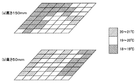
以下の条件で図5に示すような植物栽培装置10を作成し、植物50としてレタスの栽培を行なった。そして、栽培空間30内の温度分布を計測した。なお、実験のため、栽培空間30は一方に一段のみの構成としている。
A
配風手段40:18℃の空気を210m3/hで供給
ソックダクト22:ポリエステル繊維製、直径200mmの断面半円筒形、長さ900mm
チャンバーボックス20:幅1400mm、奥行400mm、高さ900mm(容量0.5m3)
栽培空間30:幅1400mm、奥行700mm、高さ550mm
開口部35:栽培パレット32の上面から50mmと150mmの高さに幅50mm、長さ1200mmのスリットを形成
風向調整板39:栽培空間30の天井面中央から200mm突設
照明手段37:32W蛍光灯各2灯を風向調整板39の両側に配置
植物50:高さ150mm、直径150mmのレタス24株を幅方向6列、奥行方向4列
Wind distribution means 40: Air at 18 ° C is supplied at 210 m 3 / h Sock duct 22: Made of polyester fiber, semi-cylindrical cross section with a diameter of 200 mm, length 900 mm
Chamber box 20: width 1400 mm, depth 400 mm, height 900 mm (capacity 0.5 m 3 )
Cultivation space 30: width 1400 mm, depth 700 mm, height 550 mm
Opening 35: A slit with a width of 50 mm and a length of 1200 mm is formed at a height of 50 mm and 150 mm from the upper surface of the
上記構成の植物栽培装置10に対し、栽培空間30を幅方向に二分した一方の領域(700mm×700mm)について、植物パレット32の上面から150mmと50mmの高さ位置における温度分布を測定した。結果を図6に示す。
With respect to the
図6を参照すると、栽培空間30内の温度は、(a)高さ150mm、(b)高さ50mmの何れにおいても、すべての領域で18℃〜21℃までの温度範囲に調整できていることがわかる。すなわち、本発明の植物栽培装置10により、栽培空間30に均質な安定した気流を発生させ、植物50の生長に最適な高さにおいて栽培に最適な環境を提供できる。
With reference to FIG. 6, the temperature in the
上記実施例の説明は、本発明を説明するためのものであって、特許請求の範囲に記載の発明を限定し、或は範囲を減縮する様に解すべきではない。又、本発明の各部構成は上記実施例に限らず、特許請求の範囲に記載の技術的範囲内で種々の変形が可能であることは勿論である。 The description of the above-described embodiment is for explaining the present invention, and should not be understood so as to limit or reduce the scope of the invention described in the claims. Further, the configuration of each part of the present invention is not limited to the above embodiment, and it goes without saying that various modifications can be made within the technical scope described in the claims.
10 植物栽培装置
20 チャンバーボックス
22 ソックダクト
30 栽培空間
32 栽培パレット
34 パネル
35 開口部(スリット)
39 風向調整板
40 配風手段
50 植物
10
39 Wind
Claims (4)
前記配風手段に連繋されたチャンバーボックスと、
前記チャンバーボックスに併設され、内部に植物の栽培パレットが配置される1段又は複数段の栽培空間と、
を具えた植物栽培装置であって、
前記チャンバーボックスと前記栽培空間は、1又は複数の開口部が形成されたパネルによって仕切られており、
前記パネルは、前記栽培空間に対して高さ方向に位置調整可能である、
ことを特徴とする植物栽培装置。 Wind distribution means and
A chamber box connected to the air distribution means and
A one-stage or multiple-stage cultivation space that is attached to the chamber box and has a plant cultivation palette inside.
It is a plant cultivation device equipped with
The chamber box and the cultivation space are separated by a panel in which one or a plurality of openings are formed .
The panel can be adjusted in height with respect to the cultivation space.
A plant cultivation device characterized by that.
請求項1に記載の植物栽培装置。 The opening is a slit elongated in the width direction of the panel.
The plant cultivation apparatus according to claim 1.
請求項1又は請求項2に記載の植物栽培装置。 A sock duct is provided in the chamber box, and the airflow from the air distribution means is introduced through the sock duct.
The plant cultivation apparatus according to claim 1 or 2 .
請求項1乃至請求項3の何れかに記載の植物栽培装置。 On the ceiling surface of the cultivation space, a wind direction adjusting plate is provided so as to project substantially parallel to the panel.
The plant cultivation apparatus according to any one of claims 1 to 3 .
Priority Applications (1)
| Application Number | Priority Date | Filing Date | Title |
|---|---|---|---|
| JP2016187054A JP6830233B2 (en) | 2016-09-26 | 2016-09-26 | Equipment for plant cultivation |
Applications Claiming Priority (1)
| Application Number | Priority Date | Filing Date | Title |
|---|---|---|---|
| JP2016187054A JP6830233B2 (en) | 2016-09-26 | 2016-09-26 | Equipment for plant cultivation |
Publications (2)
| Publication Number | Publication Date |
|---|---|
| JP2018050486A JP2018050486A (en) | 2018-04-05 |
| JP6830233B2 true JP6830233B2 (en) | 2021-02-17 |
Family
ID=61832630
Family Applications (1)
| Application Number | Title | Priority Date | Filing Date |
|---|---|---|---|
| JP2016187054A Expired - Fee Related JP6830233B2 (en) | 2016-09-26 | 2016-09-26 | Equipment for plant cultivation |
Country Status (1)
| Country | Link |
|---|---|
| JP (1) | JP6830233B2 (en) |
Families Citing this family (3)
| Publication number | Priority date | Publication date | Assignee | Title |
|---|---|---|---|---|
| JP2022505558A (en) * | 2018-11-02 | 2022-01-14 | フィースマン リフリッジレーション ソリューションズ ゲーエムベーハー | Closed climate cell for plant cultivation in multiple layers with an optimized climate system |
| CN109997570A (en) * | 2019-04-11 | 2019-07-12 | 陈锋 | A kind of forestry seedling cultivation incubator |
| CN117280974B (en) * | 2023-09-16 | 2025-08-01 | 杭州绿沙景观建设有限公司 | A seedling hardening device for green plants |
Family Cites Families (5)
| Publication number | Priority date | Publication date | Assignee | Title |
|---|---|---|---|---|
| JPS59210834A (en) * | 1983-05-16 | 1984-11-29 | 日立プラント建設株式会社 | Environment testing apparatus for plant |
| JP2001231376A (en) * | 2000-02-25 | 2001-08-28 | Toyota Motor Corp | Seedling raising device and seedling raising method |
| JP2014014285A (en) * | 2012-07-06 | 2014-01-30 | Sumitomo Mitsui Construction Co Ltd | Plants factory |
| GB201405099D0 (en) * | 2014-03-21 | 2014-05-07 | Hydrogarden Wholesale Supplies Ltd | Vertical tiered growing systems |
| JP6526976B2 (en) * | 2015-01-29 | 2019-06-05 | 大和ハウス工業株式会社 | Multistage cultivation device |
-
2016
- 2016-09-26 JP JP2016187054A patent/JP6830233B2/en not_active Expired - Fee Related
Also Published As
| Publication number | Publication date |
|---|---|
| JP2018050486A (en) | 2018-04-05 |
Similar Documents
| Publication | Publication Date | Title |
|---|---|---|
| JP6123495B2 (en) | Multistage shelf type plant growing device and plant growing system | |
| JP2022022299A (en) | Solanaceae seedling cultivation apparatus and cultivation method | |
| JP7472788B2 (en) | Apparatus and method for cultivating seedlings of solanaceae plants | |
| US10058041B2 (en) | Plant cultivation apparatus | |
| US20160157447A1 (en) | Plant cultivation apparatus | |
| JP6830233B2 (en) | Equipment for plant cultivation | |
| AU2016323373B2 (en) | Culture device and culture method | |
| EA029019B1 (en) | Greenhouse and forced greenhouse climate control system and method | |
| US20160235018A1 (en) | Air conditioning apparatus in plant cultivation | |
| JP2012000028A (en) | Plant cultivation facility | |
| JP6713107B2 (en) | Multi-stage seedling raising device | |
| JP2016140249A (en) | Multistage-type shelf, and multistage-type cultivation device equipped with the same | |
| JP3771152B2 (en) | Multistage seedling raising equipment | |
| JP5830263B2 (en) | Plant cultivation equipment | |
| JP7382229B2 (en) | Cultivation method | |
| JP2019010077A (en) | Plant cultivation device, plant cultivation system and plant cultivation method | |
| JP6676898B2 (en) | Cultivation apparatus and cultivation method | |
| CN116347976A (en) | Plant cultivation device and method | |
| JPWO2022092030A5 (en) | ||
| JP5952476B2 (en) | Plant cultivation equipment | |
| WO2017208949A1 (en) | Plant cultivation device | |
| JP2021000042A (en) | Blowing apparatus of vegetable cultivation factory | |
| JP6625685B2 (en) | Plant cultivation equipment | |
| JP2017158437A (en) | Plant cultivation apparatus and plant cultivation system | |
| JP2017046615A (en) | Air conditioning system for plants |
Legal Events
| Date | Code | Title | Description |
|---|---|---|---|
| A621 | Written request for application examination |
Free format text: JAPANESE INTERMEDIATE CODE: A621 Effective date: 20190826 |
|
| A977 | Report on retrieval |
Free format text: JAPANESE INTERMEDIATE CODE: A971007 Effective date: 20200731 |
|
| A131 | Notification of reasons for refusal |
Free format text: JAPANESE INTERMEDIATE CODE: A131 Effective date: 20200929 |
|
| A521 | Request for written amendment filed |
Free format text: JAPANESE INTERMEDIATE CODE: A523 Effective date: 20201124 |
|
| TRDD | Decision of grant or rejection written | ||
| A01 | Written decision to grant a patent or to grant a registration (utility model) |
Free format text: JAPANESE INTERMEDIATE CODE: A01 Effective date: 20210104 |
|
| A61 | First payment of annual fees (during grant procedure) |
Free format text: JAPANESE INTERMEDIATE CODE: A61 Effective date: 20210112 |
|
| R150 | Certificate of patent or registration of utility model |
Ref document number: 6830233 Country of ref document: JP Free format text: JAPANESE INTERMEDIATE CODE: R150 |
|
| LAPS | Cancellation because of no payment of annual fees |