JP6830363B2 - Gas circuit breaker - Google Patents
Gas circuit breaker Download PDFInfo
- Publication number
- JP6830363B2 JP6830363B2 JP2017003776A JP2017003776A JP6830363B2 JP 6830363 B2 JP6830363 B2 JP 6830363B2 JP 2017003776 A JP2017003776 A JP 2017003776A JP 2017003776 A JP2017003776 A JP 2017003776A JP 6830363 B2 JP6830363 B2 JP 6830363B2
- Authority
- JP
- Japan
- Prior art keywords
- shaft
- exhaust
- puffer
- conductor
- guide
- Prior art date
- Legal status (The legal status is an assumption and is not a legal conclusion. Google has not performed a legal analysis and makes no representation as to the accuracy of the status listed.)
- Active
Links
Images

Classifications
-
- H—ELECTRICITY
- H01—ELECTRIC ELEMENTS
- H01H—ELECTRIC SWITCHES; RELAYS; SELECTORS; EMERGENCY PROTECTIVE DEVICES
- H01H33/00—High-tension or heavy-current switches with arc-extinguishing or arc-preventing means
- H01H33/70—Switches with separate means for directing, obtaining, or increasing flow of arc-extinguishing fluid
- H01H33/88—Switches with separate means for directing, obtaining, or increasing flow of arc-extinguishing fluid the flow of arc-extinguishing fluid being produced or increased by movement of pistons or other pressure-producing parts
-
- H—ELECTRICITY
- H01—ELECTRIC ELEMENTS
- H01H—ELECTRIC SWITCHES; RELAYS; SELECTORS; EMERGENCY PROTECTIVE DEVICES
- H01H33/00—High-tension or heavy-current switches with arc-extinguishing or arc-preventing means
- H01H33/02—Details
- H01H33/53—Cases; Reservoirs, tanks, piping or valves, for arc-extinguishing fluid; Accessories therefor, e.g. safety arrangements, pressure relief devices
- H01H33/56—Gas reservoirs
-
- H—ELECTRICITY
- H01—ELECTRIC ELEMENTS
- H01H—ELECTRIC SWITCHES; RELAYS; SELECTORS; EMERGENCY PROTECTIVE DEVICES
- H01H33/00—High-tension or heavy-current switches with arc-extinguishing or arc-preventing means
- H01H33/70—Switches with separate means for directing, obtaining, or increasing flow of arc-extinguishing fluid
- H01H33/88—Switches with separate means for directing, obtaining, or increasing flow of arc-extinguishing fluid the flow of arc-extinguishing fluid being produced or increased by movement of pistons or other pressure-producing parts
- H01H2033/888—Deflection of hot gasses and arcing products
-
- H—ELECTRICITY
- H01—ELECTRIC ELEMENTS
- H01H—ELECTRIC SWITCHES; RELAYS; SELECTORS; EMERGENCY PROTECTIVE DEVICES
- H01H33/00—High-tension or heavy-current switches with arc-extinguishing or arc-preventing means
- H01H33/70—Switches with separate means for directing, obtaining, or increasing flow of arc-extinguishing fluid
- H01H33/72—Switches with separate means for directing, obtaining, or increasing flow of arc-extinguishing fluid having stationary parts for directing the flow of arc-extinguishing fluid, e.g. arc-extinguishing chamber
- H01H33/74—Switches with separate means for directing, obtaining, or increasing flow of arc-extinguishing fluid having stationary parts for directing the flow of arc-extinguishing fluid, e.g. arc-extinguishing chamber wherein the break is in gas
Landscapes
- Circuit Breakers (AREA)
- Arc-Extinguishing Devices That Are Switches (AREA)
Description
本発明は遮断器に関するものであり、特に電流遮断時に絶縁ガスを吹き付け、アークを消弧するガス遮断器に関する。 The present invention relates to a circuit breaker, and more particularly to a gas circuit breaker that blows an insulating gas to extinguish an arc when a current is cut off.
発生した熱ガスを冷却する排気構造として特許文献1に記載の発明がある。この発明は、可動側のパッファシャフトと可動側排気導体の間に、排気されたガスの流れを変えるための冷却羽を配置した構造である。排気された高温の熱ガスが冷却羽に当たることで、周囲の低温ガスとの撹拌が促進され、高温ガスは冷却される。排気筒から排出される高温ガスが冷却されることで、遮断器の対地絶縁性能を向上させている。
There is an invention described in
特許文献1に記載の発明では、可動側のパッファシャフトと可動側排気導体の間に、冷却羽を配置しているため、可動側の排気構造にとっては常に排気の流路抵抗が大きな状態となり、極間の熱ガス排気の妨げとなり、極間の遮断性能が低下するという課題がある。
In the invention described in
上記課題を解決するために、本発明のガス遮断器は、ガスタンク内に開極及び閉極動作を可能に対向配置した一対のアーク接触子と、前記一対のアーク接触子の一方に同軸上に連結されたパッファシャフトと、前記パッファシャフトは周方向にシャフト排気穴を有し、前記パッファシャフトの外周に同軸上に設けられたパッファシリンダと、前記パッファシリンダと前記パッファシャフトの間の空間に設けられたパッファピストンと、前記パッファシリンダの遮断部側に固定した絶縁ノズルと、前記パッファシャフトと操作器を連結する絶縁ロッドと、前記パッファシャフトと絶縁ロッドの連結部の外周に設けられたシャフトガイドと、前記シャフトガイドは周方向にシャフトガイド排気穴を有し、前記シャフトガイドの同心円状の外周に位置するように、前記パッファピストンの操作器側に固定して設けられた排気ガイドと、前記排気ガイドの外周に支持絶縁物でガスタンクの内壁に支持された可動側排気導体を有し、前記可動側排気導体は外周に導体排気穴を有し、遮断動作で生じた熱ガスを、遮断動作途中はパッファシャフトのシャフト排気穴、パッファシャフトとシャフトガイドで形成される空間、シャフトガイドと排気ガイドで形成される空間、排気ガイドと可動側排気導体で形成される空間、可動側排気導体の導体排気穴を通して、ガスタンク内に熱ガスを排出する第一の形態と、パッファシャフトのシャフト排気穴とシャフトガイドのシャフトガイド排気穴が連通し、シャフト排気穴、シャフトガイド排気穴、排気ガイドと可動側排気導体で形成される空間、可動側排気導体の導体排気穴を通して、ガスタンク内に熱ガスを排気する第二の形態を有することを特徴とする。
In order to solve the above problems, the gas breaker of the present invention has a pair of arc contacts arranged so as to enable open and closed operations in a gas tank and one of the pair of arc contacts coaxially. The connected puffer shaft and the puffer shaft have shaft exhaust holes in the circumferential direction, and are provided in a space between the puffer cylinder and the puffer shaft provided coaxially on the outer periphery of the puffer shaft. The puffer piston, the insulating nozzle fixed to the blocking portion side of the puffer cylinder, the insulating rod connecting the puffer shaft and the operator, and the shaft guide provided on the outer periphery of the connecting portion between the puffer shaft and the insulating rod. The shaft guide has a shaft guide exhaust hole in the circumferential direction, and is fixed to the operator side of the puffer piston so as to be located on the concentric outer periphery of the shaft guide. The movable side exhaust conductor is supported on the inner wall of the gas tank by a supporting insulator on the outer periphery of the exhaust guide, and the movable side exhaust conductor has a conductor exhaust hole on the outer periphery, and the heat gas generated by the shutoff operation is cut off. On the way, the shaft exhaust hole of the puffer shaft, the space formed by the puffer shaft and the shaft guide, the space formed by the shaft guide and the exhaust guide, the space formed by the exhaust guide and the movable side exhaust conductor, the conductor of the movable side exhaust conductor. The first form of discharging hot gas into the gas tank through the exhaust hole, and the shaft exhaust hole of the puffer shaft and the shaft guide exhaust hole of the shaft guide communicate with each other, and the shaft exhaust hole, shaft guide exhaust hole, exhaust guide and movable side It is characterized by having a second form of exhausting hot gas into a gas tank through a space formed by an exhaust conductor and a conductor exhaust hole of a movable side exhaust conductor.
本発明は、遮断動作途中では極間で生じた熱ガスを、パッファシャフトのシャフト排気穴、パッファシャフトとシャフトガイドで形成される空間、可動側排気導体とその導体排気穴の流路を通してからガスタンク内に熱ガスを排出することで、ガスタンク内に排気するときには冷却され、絶縁性能が向上する。また、遮断動作終了前の電流零点近くの領域にかけて、パッファシャフトのシャフト排気穴とシャフトガイドのシャフトガイド排気穴が連通することで、排気流路が短縮され、排気流路の抵抗が小さくなり、極間のガスを効率よく排気されて、極間の遮断性能を向上させることができる。 In the present invention, the heat gas generated between the poles during the shutoff operation is passed through the shaft exhaust hole of the puffer shaft, the space formed by the puffer shaft and the shaft guide, the movable side exhaust conductor and the flow path of the conductor exhaust hole, and then the gas tank. By discharging the hot gas inside, it is cooled when it is exhausted into the gas tank, and the insulation performance is improved. In addition, the shaft exhaust hole of the puffer shaft and the shaft guide exhaust hole of the shaft guide communicate with each other over the region near the current zero point before the end of the cutoff operation, so that the exhaust flow path is shortened and the resistance of the exhaust flow path is reduced. The gas between the poles can be efficiently exhausted, and the blocking performance between the poles can be improved.
以下、図面を用いて本発明の実施例について説明する。下記はあくまでも実施の例であり、発明の内容を下記具体的態様に限定することを意図する趣旨ではない。発明自体は、特許請求の範囲に記載された内容に即した限りにおいて種々の態様で実施することが可能である。 Hereinafter, examples of the present invention will be described with reference to the drawings. The following is just an example of implementation, and is not intended to limit the content of the invention to the following specific aspects. The invention itself can be implemented in various aspects as long as it conforms to the contents described in the claims.
図1を用いて遮断動作時におけるガス遮断器の概要構造と動作について示す。 FIG. 1 shows the outline structure and operation of the gas circuit breaker during the circuit breaker operation.
ガス遮断器は絶縁ガスが充填されたガスタンク1内に収納されている。図1において省略しているが、遮断器はパッファシャフト6が絶縁ロッド17を介して操作器(不図示)と接続されており、遮断器全体はSF6ガスが充填されたガスタンク1内に配置される。
The gas circuit breaker is housed in a
図1に示されるように、遮断器は固定側アーク接触子3と可動側アーク接触子2と、パッファシリンダ8と、パッファシリンダ8とパッファピストン7とパッファシャフト6と可動子カバー11と絶縁ノズル10によって囲まれた空間で構成されるパッファ室9と、可動側主接触子4と固定側主接触子5と導体18とシールド14とシャフトガイド19と可動側排気導体15で概略構成される。
As shown in FIG. 1, the circuit breaker includes a
固定側導体12と固定側排気筒13は金属支持構造物を通して固定側アーク接触子3に電気的に接続されており、電気的に接続された可動側アーク接触子2とパッファシャフト6とパッファピストン7とパッファシリンダ8と可動側主接触子4は、通電状態(閉極状態)において固定側とそれぞれ電気的に接続される。
The fixed-
パッファ室9は、上記パッファシリンダ8と、パッファシリンダ8の内周に同軸上に配置されて、内部が中空となっており、該中空内に絶縁ガスが流入するパッファシャフト6と、パッファシリンダ8とパッファシャフト6の間に形成された空間を摺動するパッファピストン7で形成される。
The
操作器側の遮断部はガスタンク1の内周面に設けられた取り付け座に支持絶縁物16で固定されている。
The blocking portion on the actuator side is fixed to a mounting seat provided on the inner peripheral surface of the
通常、操作器側の可動側アーク接触子2と反対側の固定側アーク接触子3および、可動側主接触子4と固定側主接触子5は電気的に接続されているが、事故時に開極指令が伝えられるとパッファシャフト6と絶縁ロッド17を介して操作器(不図示)により可動側が動作し、固定側の固定側アーク接触子3と可動側の可動側アーク接触子2、固定側主接触子5と可動側主接触子4がそれぞれ物理的に開離された状態に移行する。
Normally, the movable arc contact 2 on the actuator side and the
接触子が開離した後も、固定側アーク接触子3と可動側アーク接触子2間には電流が流れ、アークが発生する。ガス遮断器はアークに高圧の絶縁ガスを吹き付け消弧するため、可動側動作の際にパッファピストン7でパッファ室9内の絶縁ガスの圧縮が行われ、アークへのガス吹付が行われ、アークの消孤が行われる。
Even after the contacts are separated, a current flows between the fixed-
アークに吹付けられる絶縁ガスのパッファ室9内における圧力形成は、可動するパッファシリンダ8が固定されたパッファピストン7に対し相対的に移動することにより行われる。より詳細には、図示されていない操作器に接続された絶縁ロッド17からパッファシャフト6を通じてパッファシリンダ8に操作器の駆動力が伝達され、パッファシリンダ8が紙面右側に動くことでパッファ室9内の絶縁ガスが圧縮される。
The pressure formation in the
パッファ室9内で圧縮された高圧の絶縁ガスは遮断動作時に固定側アーク接触子3と可動側アーク接触子2間に、発生したアークに対して吹付けられる。アークに吹き付けられた後に発生する高温の熱ガスは、固定側と操作器側にそれぞれ排出され固定側には絶縁ノズル10、固定側排気筒13の内部を通り、冷却されながらガスタンク1内に排出される。
The high-pressure insulating gas compressed in the
操作器側にはパッファシャフト6のシャフト排気穴21を通して、可動側排気導体15に排出され、その後、可動側排気導体15の導体排気穴22を通してガスタンク1内に排出される。なお、図1から図6において導体排気穴22は位置関係が分かり易くなるため同じ断面図上に示したが、実際には図7に示す位置関係となっている。
On the actuator side, it is discharged to the movable
ガス吹付の際に発生した熱ガスは高温で密度が低くなっており、絶縁耐力が低い状態となっている。極間の絶縁性能の低下を防ぐため消弧が成功した後に熱ガスは速やかに排出する必要があり、絶縁ノズル10とパッファシャフト6を通じて、固定側と可動側へそれぞれ排気される。
The heat gas generated during gas spraying has a low density at a high temperature, and has a low dielectric strength. In order to prevent deterioration of the insulation performance between the poles, it is necessary to promptly discharge the hot gas after the arc is successfully extinguished, and the heat gas is exhausted to the fixed side and the movable side through the
排気筒の役割は発生した熱ガスを電極間に滞留させず速やかに排出することと、熱ガスを効率的に冷却することである。 The role of the exhaust stack is to quickly discharge the generated heat gas without staying between the electrodes and to cool the heat gas efficiently.
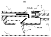
図2を用いて、可動側排気導体15とガスタンク1間での絶縁破壊の発生のメカニズムについて説明する。ガスの冷却が不十分で密度の低下したままの高温で絶縁耐力が低い熱ガスが可動側排気導体15の導体排気穴22の端部の高電界部に達すると可動側排気導体15とガスタンク1間の絶縁耐力が低下し、可動側排気導体15とガスタンク1との間で絶縁破壊を生じる事故(地絡)が発生する可能性がある。
The mechanism of dielectric breakdown between the
地絡事故に対しては、ガスタンク径を拡大することにより、可動側排気導体15とガスタンク1間の電界緩和による対地絶縁性能を得る手段や、排気筒拡大による熱ガスの冷却能力を向上させるといった手段がとられている。ただし、このような手段では、遮断部構造、排気・シールド構造の大型化に繋がる。また、近年、電力系統の高電圧・大電流化が進んでおり、必要な遮断性能を得るためにガス遮断器の大容量化が進められている一方で、コスト低減のため、遮断部構造、排気・シールド構造の最適化による小型化も進められており、これらに反することになる。
In the event of a ground fault, by increasing the diameter of the gas tank, it is possible to improve the means for obtaining ground insulation performance by relaxing the electric field between the
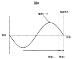
図8はガス遮断器に流れる遮断電流を遮断動作途中の領域Aと、最終半波の電流ピークを越えて電流零点に向かう遮断電流が小さくなる領域Bを表した説明図である。領域Aではアークエネルギーが増加し、排気される熱ガスの温度も高く、流速も速いガスとなる。領域Bでは電流ピークを過ぎて、アークエネルギーが小さくなるため、発生するガス温度も低下し、流速も遅くなる。電流零点では、極間に印加される回復電圧に耐えるために、極間の熱ガスを十分に排気することも必要となる。 FIG. 8 is an explanatory diagram showing a region A in the middle of the interrupting operation of the breaking current flowing through the gas circuit breaker and a region B in which the breaking current beyond the current peak of the final half wave and toward the current zero becomes small. In region A, the arc energy increases, the temperature of the exhausted hot gas is high, and the flow velocity is high. In the region B, since the current peak is passed and the arc energy becomes small, the generated gas temperature also decreases and the flow velocity becomes slow. At the current zero, it is also necessary to sufficiently exhaust the heat gas between the poles in order to withstand the recovery voltage applied between the poles.
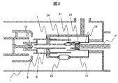
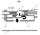
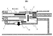
図3で実施例1での遮断動作途中の熱ガスの排気流路について説明する。なお、図1と同様の部分については説明を省略する。図3の遮断動作途中の断面図で説明されるようにシャフトガイド19を固定側に延長し、周方向にシャフトガイド排気穴23を有するシャフトガイド19と、シャフトガイド19の同心円状の外周に位置するような排気ガイド24をパッファピストン7の操作器側に固定設置する。図4の遮断動作途中の熱ガスの排気ガス流路の拡大断面図で説明されるように極間で発生した熱ガスはパッファシャフト6のシャフト排気穴21から排出され、パッファシャフト6とシャフトガイド19で形成される空間に流れる。その後はシャフトガイド19と排気ガイド24で形成される流路を通して、可動側排気導体15内に排気され、導体排気穴22を通してガスタンク1内に排気される。
FIG. 3 describes an exhaust flow path of the hot gas during the shutoff operation in the first embodiment. The same parts as in FIG. 1 will not be described. The
このように遮断動作途中に発生した流れの速い熱ガスはシャフトガイド19と排気ガイド24で形成される流路を通る間に冷却され、導体排気穴22の高電界部に到達するときには十分な絶縁性能を有する温度になる。
The fast-flowing heat gas generated during the shutoff operation is cooled while passing through the flow path formed by the
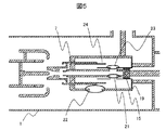
次に遮断動作終了直前のガス流路について図5と図6を用いて説明する。図5はガス遮断器の遮断動作終了前の断面図であり、遮断部の位置関係を示した図である。図6は遮断動作終了前の熱ガスの排気流路を説明する拡大断面図であり、可動側排気導体15周辺の拡大断面図である。図6で示すようにシャフト排気穴21とシャフトガイド排気穴23は連通し、直接可動側排気導体15に排気される位置関係となる。図4で示した遮断動作途中の流路より、導体排気穴22までの流路が短くなり、流路抵抗が小さくなる。そのため、電流ピークを過ぎ、アークエネルギーが小さくなり、流速が遅くなった熱ガスも極間から十分に排気することができ、極間性能の低下を防ぐことができる。
Next, the gas flow path immediately before the end of the shutoff operation will be described with reference to FIGS. 5 and 6. FIG. 5 is a cross-sectional view of the gas circuit breaker before the end of the circuit breaker operation, and is a diagram showing the positional relationship of the circuit breaker. FIG. 6 is an enlarged cross-sectional view for explaining the exhaust flow path of the hot gas before the end of the shutoff operation, and is an enlarged cross-sectional view around the movable
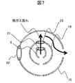
図7はガス遮断器の遮断動作終了前におけるパッファシャフトのシャフト排気穴21とシャフトガイドのシャフトガイド排気穴23と可動側導体の導体排気穴22の排気穴の位置関係を示した断面図である。
FIG. 7 is a cross-sectional view showing the positional relationship between the
図7に示すようにシャフト排気穴21とシャフトガイド排気穴23は紙面上下方向に連通し、導体排気穴22は90度違いの左右方向に配置している。このように90度で互い違いに穴を配置することで、シャフト排気穴21とシャフトガイド排気穴23から出てきた熱ガスを可動側排気導体15の内壁にぶつけてから、導体排気穴22を通してガスタンク1内に排気することができる。導体排気穴22に直接排気する場合と比較して、可動側排気導体15内を迂回させることで熱ガスの冷却効果が得られる。
As shown in FIG. 7, the
上記実施例でのシャフト排気穴21とシャフトガイド排気穴23が2個で、紙面上下方向に開けた場合の例だが、穴の数を変更した場合でも同様に周方向に互い違いになるように排気穴を配置することで、同様の冷却効果を得ることができる。
In the above embodiment, the
上記実施例ではパッファピストン7の機械圧縮で吹付ガス圧力を得るパッファタイプの遮断器での例だが、容積固定の熱パッファ室を設け、アーク熱を取り込むことで吹付ガス圧力を得る熱パッファタイプの遮断器に本発明を適用することも可能である。 In the above embodiment, the blower gas pressure is obtained by mechanical compression of the puffer piston 7, but the heat puffer type circuit breaker is provided with a fixed volume heat puffer chamber and takes in arc heat to obtain the blown gas pressure. It is also possible to apply the present invention to a circuit breaker.
本実施例では絶縁ガスとしてSF6を使用したが、絶縁ガスの種類はSF6に限られるものでなく、乾燥空気・窒素ガス等他の絶縁ガスを使用できる。 Although SF6 is used as the insulating gas in this embodiment, the type of insulating gas is not limited to SF6, and other insulating gases such as dry air and nitrogen gas can be used.
以上、本実施例によれば、遮断動作途中では極間で生じた熱ガスを、パッファシャフトのシャフト排気穴、パッファシャフトとシャフトガイドで形成される空間、可動側排気導体とその導体排気穴の流路を通してからガスタンク内に熱ガスを排出することで、ガスタンク内に排気するときには冷却され、絶縁性能が向上する。また、遮断動作終了前の電流零点近くの領域にかけて、パッファシャフトのシャフト排気穴とシャフトガイドのシャフトガイド排気穴が連通することで、排気流路が短縮され、排気流路の抵抗が小さくなり、極間のガスを効率よく排気されて、極間の遮断性能を向上させることができる。 As described above, according to this embodiment, the heat gas generated between the poles during the shutoff operation is transferred to the shaft exhaust hole of the puffer shaft, the space formed by the puffer shaft and the shaft guide, the movable side exhaust conductor and the conductor exhaust hole. By discharging hot gas into the gas tank after passing through the flow path, it is cooled when it is exhausted into the gas tank, and the insulation performance is improved. In addition, the shaft exhaust hole of the puffer shaft and the shaft guide exhaust hole of the shaft guide communicate with each other over the region near the current zero point before the end of the cutoff operation, so that the exhaust flow path is shortened and the resistance of the exhaust flow path is reduced. The gas between the poles can be efficiently exhausted, and the blocking performance between the poles can be improved.
1:ガスタンク
2:可動側アーク接触子
3:固定側アーク接触子
4:可動側主接触子
5:固定側主接触子
6:パッファシャフト
7:パッファピストン
8:パッファシリンダ
9:パッファ室
10:絶縁ノズル
11:可動子カバー
12:固定側導体
13:固定側排気筒
14:シールド
15:可動側排気導体
16:支持絶縁物
17:絶縁ロッド
18:導体
19:シャフトガイド
21:シャフト排気穴
22:導体排気穴
23:シャフトガイド排気穴
24:排気ガイド
1: Gas tank 2: Movable side arc contactor 3: Fixed side arc contactor 4: Movable side main contactor 5: Fixed side main contactor 6: Puffer shaft 7: Puffer piston 8: Puffer cylinder 9: Puffer chamber 10: Insulation Nozzle 11: Movable conductor cover 12: Fixed side conductor 13: Fixed side exhaust pipe 14: Shield 15: Movable side exhaust conductor 16: Support insulator 17: Insulation rod 18: Conductor 19: Shaft guide 21: Shaft exhaust hole 22: Conductor Exhaust hole 23: Shaft guide Exhaust hole 24: Exhaust guide
Claims (3)
前記一対のアーク接触子の一方に同軸上に連結されたパッファシャフトと、
前記パッファシャフトは周方向にシャフト排気穴を有し、
前記パッファシャフトの外周に同軸上に設けられたパッファシリンダと、
前記パッファシリンダと前記パッファシャフトの間の空間に設けられたパッファピストンと、
前記パッファシリンダの遮断部側に固定した絶縁ノズルと、
前記パッファシャフトと操作器を連結する絶縁ロッドと、
前記パッファシャフトと絶縁ロッドの連結部の外周に設けられたシャフトガイドと、
前記シャフトガイドは周方向にシャフトガイド排気穴を有し、
前記シャフトガイドの同心円状の外周に位置するように、前記パッファピストンの操作器側に固定して設けられた排気ガイドと、
前記排気ガイドの外周に支持絶縁物でガスタンクの内壁に支持された可動側排気導体を有し、
前記可動側排気導体は外周に導体排気穴を有し、
遮断動作で生じた熱ガスを、遮断動作途中はパッファシャフトのシャフト排気穴、パッファシャフトとシャフトガイドで形成される空間、シャフトガイドと排気ガイドで形成される空間、排気ガイドと可動側排気導体で形成される空間、可動側排気導体の導体排気穴を通して、ガスタンク内に熱ガスを排出する第一の形態と、パッファシャフトのシャフト排気穴とシャフトガイドのシャフトガイド排気穴が連通し、シャフト排気穴、シャフトガイド排気穴、排気ガイドと可動側排気導体で形成される空間、可動側排気導体の導体排気穴を通して、ガスタンク内に熱ガスを排気する第二の形態を有することを特徴とする、ガス遮断器。 A pair of arc contacts arranged facing each other in the gas tank to enable open and closed operations,
A puffer shaft coaxially connected to one of the pair of arc contacts,
The puffer shaft has a shaft exhaust hole in the circumferential direction.
A puffer cylinder coaxially provided on the outer circumference of the puffer shaft,
A puffer piston provided in the space between the puffer cylinder and the puffer shaft,
An insulating nozzle fixed to the cutoff side of the puffer cylinder and
An insulating rod that connects the puffer shaft and the actuator,
A shaft guide provided on the outer circumference of the connecting portion between the puffer shaft and the insulating rod,
The shaft guide has a shaft guide exhaust hole in the circumferential direction.
An exhaust guide fixed to the actuator side of the puffer piston so as to be located on the concentric outer circumference of the shaft guide, and an exhaust guide.
A movable exhaust conductor supported on the inner wall of the gas tank by a supporting insulator is provided on the outer periphery of the exhaust guide.
The movable exhaust conductor has a conductor exhaust hole on the outer circumference.
During the shutoff operation, the heat gas generated by the shutoff operation is discharged by the shaft exhaust hole of the puffer shaft, the space formed by the puffer shaft and the shaft guide, the space formed by the shaft guide and the exhaust guide, and the exhaust guide and the movable exhaust conductor. The first form of discharging hot gas into the gas tank through the space formed and the conductor exhaust hole of the movable side exhaust conductor, and the shaft exhaust hole of the puffer shaft and the shaft guide exhaust hole of the shaft guide communicate with each other, and the shaft exhaust hole The gas is characterized by having a second form of exhausting hot gas into a gas tank through a shaft guide exhaust hole, a space formed by an exhaust guide and a movable side exhaust conductor, and a conductor exhaust hole of the movable side exhaust conductor. Breaker.
遮断動作開始時の領域にかけては、第一の形態となり、遮断動作終了前の電流零点近くの領域にかけては、第二の形態となり、排気流路が変化することを特徴とする、ガス遮断器。 In the gas circuit breaker according to claim 1,
A gas circuit breaker characterized in that the region at the start of the cutoff operation is in the first form, and the region near the current zero point before the end of the cutoff operation is in the second form, and the exhaust flow path changes.
前記パッファシャフトのシャフト排気穴とシャフトガイドのシャフトガイド排気穴は、前記可動側排気導体の導体排気穴と周方向に互い違いに配置することを特徴とするガス遮断器。 In the gas circuit breaker according to any one of claims 1 or 2.
A gas circuit breaker characterized in that the shaft exhaust hole of the puffer shaft and the shaft guide exhaust hole of the shaft guide are alternately arranged in the circumferential direction with the conductor exhaust hole of the movable side exhaust conductor.
Priority Applications (2)
| Application Number | Priority Date | Filing Date | Title |
|---|---|---|---|
| JP2017003776A JP6830363B2 (en) | 2017-01-13 | 2017-01-13 | Gas circuit breaker |
| US15/855,170 US20180226214A1 (en) | 2017-01-13 | 2017-12-27 | Gas Breaker |
Applications Claiming Priority (1)
| Application Number | Priority Date | Filing Date | Title |
|---|---|---|---|
| JP2017003776A JP6830363B2 (en) | 2017-01-13 | 2017-01-13 | Gas circuit breaker |
Publications (2)
| Publication Number | Publication Date |
|---|---|
| JP2018113189A JP2018113189A (en) | 2018-07-19 |
| JP6830363B2 true JP6830363B2 (en) | 2021-02-17 |
Family
ID=62912510
Family Applications (1)
| Application Number | Title | Priority Date | Filing Date |
|---|---|---|---|
| JP2017003776A Active JP6830363B2 (en) | 2017-01-13 | 2017-01-13 | Gas circuit breaker |
Country Status (2)
| Country | Link |
|---|---|
| US (1) | US20180226214A1 (en) |
| JP (1) | JP6830363B2 (en) |
Families Citing this family (3)
| Publication number | Priority date | Publication date | Assignee | Title |
|---|---|---|---|---|
| EP3503153B1 (en) | 2017-12-22 | 2021-09-01 | ABB Power Grids Switzerland AG | Gas-insulated high or medium voltage circuit breaker |
| EP3503152B1 (en) * | 2017-12-22 | 2020-10-14 | ABB Power Grids Switzerland AG | Gas-insulated high or medium voltage circuit breaker |
| US12322935B2 (en) * | 2022-08-23 | 2025-06-03 | Siemens Energy Global GmbH & Co. KG | Compressed gas switch |
Family Cites Families (3)
| Publication number | Priority date | Publication date | Assignee | Title |
|---|---|---|---|---|
| JP4518588B2 (en) * | 1999-03-16 | 2010-08-04 | 三菱電機株式会社 | Gas circuit breaker |
| JP2013125720A (en) * | 2011-12-16 | 2013-06-24 | Hitachi Ltd | Puffer type gas circuit breaker |
| JP6244262B2 (en) * | 2014-05-16 | 2017-12-06 | 株式会社日立製作所 | Gas circuit breaker |
-
2017
- 2017-01-13 JP JP2017003776A patent/JP6830363B2/en active Active
- 2017-12-27 US US15/855,170 patent/US20180226214A1/en not_active Abandoned
Also Published As
| Publication number | Publication date |
|---|---|
| JP2018113189A (en) | 2018-07-19 |
| US20180226214A1 (en) | 2018-08-09 |
Similar Documents
| Publication | Publication Date | Title |
|---|---|---|
| JP6667370B2 (en) | Gas circuit breaker | |
| CN104584171A (en) | gas circuit breaker | |
| JP6818604B2 (en) | Gas circuit breaker | |
| JP6830363B2 (en) | Gas circuit breaker | |
| JP2910582B2 (en) | Gas circuit breaker for electric power | |
| US9147539B2 (en) | High voltage gas circuit breaker | |
| WO2013175565A1 (en) | Gas circuit breaker | |
| JP6659864B2 (en) | Gas circuit breaker | |
| JP2013125720A (en) | Puffer type gas circuit breaker | |
| JP4879366B1 (en) | Gas circuit breaker | |
| JP2021039912A (en) | Gas circuit breaker | |
| KR101291789B1 (en) | Gas insulated switchgear | |
| KR101605142B1 (en) | Gas isolated circuit breaker | |
| JP6914801B2 (en) | Gas circuit breaker | |
| JPS6236336B2 (en) | ||
| JP6363038B2 (en) | Gas circuit breaker | |
| JP6564331B2 (en) | Gas circuit breaker | |
| JP2022029718A (en) | Gas-blast circuit breaker | |
| JP2007035518A (en) | Gas circuit breaker | |
| JP2021177447A (en) | Gas circuit breaker | |
| JP2604742Y2 (en) | Thermal puffer type gas circuit breaker | |
| WO2020003854A1 (en) | Gas circuit breaker | |
| JP2024061190A (en) | Gas Circuit Breaker | |
| JP2020091939A (en) | Gas circuit breaker | |
| JP2017204416A (en) | Gas circuit breaker |
Legal Events
| Date | Code | Title | Description |
|---|---|---|---|
| A621 | Written request for application examination |
Free format text: JAPANESE INTERMEDIATE CODE: A621 Effective date: 20190729 |
|
| A977 | Report on retrieval |
Free format text: JAPANESE INTERMEDIATE CODE: A971007 Effective date: 20200707 |
|
| A131 | Notification of reasons for refusal |
Free format text: JAPANESE INTERMEDIATE CODE: A131 Effective date: 20200721 |
|
| A521 | Request for written amendment filed |
Free format text: JAPANESE INTERMEDIATE CODE: A523 Effective date: 20200911 |
|
| TRDD | Decision of grant or rejection written | ||
| A01 | Written decision to grant a patent or to grant a registration (utility model) |
Free format text: JAPANESE INTERMEDIATE CODE: A01 Effective date: 20201228 |
|
| A61 | First payment of annual fees (during grant procedure) |
Free format text: JAPANESE INTERMEDIATE CODE: A61 Effective date: 20210126 |
|
| R150 | Certificate of patent or registration of utility model |
Ref document number: 6830363 Country of ref document: JP Free format text: JAPANESE INTERMEDIATE CODE: R150 |
|
| R250 | Receipt of annual fees |
Free format text: JAPANESE INTERMEDIATE CODE: R250 |
|
| S111 | Request for change of ownership or part of ownership |
Free format text: JAPANESE INTERMEDIATE CODE: R313113 |
|
| R350 | Written notification of registration of transfer |
Free format text: JAPANESE INTERMEDIATE CODE: R350 |
|
| R250 | Receipt of annual fees |
Free format text: JAPANESE INTERMEDIATE CODE: R250 |