JP6830375B2 - Gimbal device, attitude detector, surveying device, surveying pole, and flying vehicle - Google Patents
Gimbal device, attitude detector, surveying device, surveying pole, and flying vehicle Download PDFInfo
- Publication number
- JP6830375B2 JP6830375B2 JP2017032977A JP2017032977A JP6830375B2 JP 6830375 B2 JP6830375 B2 JP 6830375B2 JP 2017032977 A JP2017032977 A JP 2017032977A JP 2017032977 A JP2017032977 A JP 2017032977A JP 6830375 B2 JP6830375 B2 JP 6830375B2
- Authority
- JP
- Japan
- Prior art keywords
- electrical connection
- axis
- gimbal
- motor
- inner frame
- Prior art date
- Legal status (The legal status is an assumption and is not a legal conclusion. Google has not performed a legal analysis and makes no representation as to the accuracy of the status listed.)
- Active
Links
Images


Landscapes
- Arrangements For Transmission Of Measured Signals (AREA)
Description
本発明はジンバル装置、それを用いた姿勢検出装置、測量装置、測量用ポール、及び飛行移動体に関する。 The present invention relates to a gimbal device, a posture detection device using the gimbal device, a surveying device, a surveying pole, and a flying mobile body.
移動体にカメラを設けて撮影する際に視軸振れを抑制するためや、測量用ポールを常に鉛直方向とするため等、姿勢を安定化させるための機構としてジンバル機構が種々の装置に用いられている。 A gimbal mechanism is used in various devices as a mechanism for stabilizing the posture, such as to suppress the visual axis shake when a camera is provided on a moving body and to always keep the surveying pole in the vertical direction. ing.
例えば、特許文献1では、2軸のジンバル機構を介して傾斜検出ユニットを支持し、当該傾斜検出ユニットにより水平を検出した後、当該ジンバル機構の各軸の回転角を検出することで、当該傾斜検出ユニットを搭載している装置の姿勢検出を行う技術が開示されている。
For example, in
特許文献1では、ジンバル機構を構成する外フレーム、内フレーム、及び傾斜検出ユニットの回転を制約するものがなく、傾斜検出ユニット、内フレームはともに360°以上の回転が可能であるものとして記載しているが、実際には傾斜検出ユニットやモータへの電力供給や制御信号の授受のための配線を設ける必要がある。
しかしながら、配線類がジンバル機構の回転体である外フレーム、内フレーム、及び傾斜検出ユニットの間に跨って設けられると、各回転体の回転が妨げられるおそれがある。 However, if the wiring is provided across the outer frame, the inner frame, and the inclination detection unit, which are the rotating bodies of the gimbal mechanism, the rotation of each rotating body may be hindered.
これに対し、回転を許容しつつ給電及び通信が可能な機構として、リング状の電極にブラシを摺接させることで電気的接続を実現させるスリップリングが知られている。しかし、このような構成のスリップリングは、回転動作時に電気接続が瞬断されたり、長期間の使用により接点が摩耗したり、その摩耗紛による障害発生や電気接続状況の悪化を招いたり、ブラシの摺接による摩擦が回転動作の抵抗となり、回転動作の応答性低下や回転負荷の増加を招く等、種々の問題を抱えている。したがって、ジンバル機構へのスリップリングの適用は必ずしも好ましいものではない。 On the other hand, as a mechanism capable of supplying power and communicating while allowing rotation, a slip ring that realizes an electrical connection by sliding a brush against a ring-shaped electrode is known. However, a slip ring with such a configuration may cause a momentary disconnection of the electrical connection during rotational operation, wear of the contacts due to long-term use, failure due to the wear dust, deterioration of the electrical connection status, or a brush. Friction due to sliding contact becomes resistance to rotational operation, which causes various problems such as a decrease in responsiveness of rotational operation and an increase in rotational load. Therefore, the application of slip rings to the gimbal mechanism is not always preferable.
本発明はこのような問題点を解決するためになされたもので、その目的とするところは回転体の回転を妨げることなく、信頼性の高い回転体間の電気接続を実現し、且つ回転体の回転応答性の向上と回転抵抗の低減を実現することのできるジンバル装置、姿勢検出装置、測量装置、測量用ポール、及び飛行移動体を提供することにある。 The present invention has been made to solve such a problem, and an object of the present invention is to realize highly reliable electrical connection between rotating bodies without hindering the rotation of the rotating body, and to realize a rotating body. It is an object of the present invention to provide a gimbal device, an attitude detection device, a survey device, a survey pole, and a flying moving body capable of improving the rotational responsiveness and reducing the rotational resistance.
上記した目的を達成するために、本発明に係るジンバル装置では、所定の部品を少なくとも2軸において回転自在に支持するジンバル装置であって、前記部品を支持する部品支持部と、前記部品支持部を第1の軸を回転軸として回転自在に支持する内フレームと、前記内フレームを第2の軸を回転軸として回転自在に支持する外フレームと、前記部品支持部と前記内フレームとの間にて、前記第1の軸回りの回転を許容しつつ非接触な電気的接続を行う内側電気接続部と、前記内フレームと前記外フレームとの間にて、前記第2の軸回りの回転を許容しつつ非接触な電気的接続を行う外側電気接続部と、前記内側電気接続部及び前記外側電気接続部を介して、前記部品から前記外フレームまで敷設された配線と、を備え、前記内側電気接続部及び前記外側電気接続部は、回転軸と同軸上にて先端が対向した一対の光ファイバを含む。
In order to achieve the above object, the gimbal device according to the present invention is a gimbal device that rotatably supports a predetermined component in at least two axes, and is a component support portion that supports the component and a component support portion. Between the inner frame that rotatably supports the inner frame with the first axis as the rotation axis, the outer frame that rotatably supports the inner frame with the second axis as the rotation axis, and the component support portion and the inner frame. The rotation around the second axis is performed between the inner frame and the outer frame, which makes a non-contact electrical connection while allowing the rotation around the first axis. an outer electrical connecting unit for performing non-contact electrical connection while allowing, through the inner electrical connecting portion and the outer electrical connections, provided with the wiring and laid up the outer frame from said component, said The inner electrical connection and the outer electrical connection include a pair of optical fibers whose tips face each other coaxially with the axis of rotation .
また、前記ジンバル装置の、前記内側電気接続部及び前記外側電気接続部は、相互誘電作用を利用した無線給電部を含んでもよい。 Further, the inner electrical connection portion and the outer electrical connection portion of the gimbal device may include a wireless power feeding portion utilizing an interaction.
さらに、前記ジンバル装置は、前記内フレームに対して前記部品支持部を前記第1の軸回りに回転駆動する第1のモータと、前記外フレームに対して前記内フレームを前記第2の軸回りに回転駆動する第2のモータと、を備え、前記第1のモータ及び第2のモータへの配線は、前記部品から前記外フレームまで敷設された配線のうち前記内フレームに沿って敷設される部分に含まれていてもよい。 Further, the gimbal device includes a first motor that rotationally drives the component support portion around the first axis with respect to the inner frame, and the inner frame around the second axis with respect to the outer frame. and a second motor for rotationally driving the said first wiring to the motor and the second motor, Ru is laid along the frame of the laid wires from the component to the outer frame It may be included in the part .
好ましくは、前記第1のモータ及び前記第2のモータは、いずれもステータが前記内フレームに設けられている。 Preferably, both the first motor and the second motor have a stator provided on the inner frame.
また、本発明に係る姿勢検出装置は、上述のジンバル装置を有し、さらに、前記部品として前記部品支持部に設けられ、水平を検出する水平検出部と、前記部品支持部に対する前記内フレームの前記第1の軸回りの角度を検出する第1のエンコーダと、前記内フレームに対する前記外フレームの前記第2の軸回りの角度を検出する第2のエンコーダと、前記第1のモータ及び第2のモータを駆動して、前記水平検出部により水平が検出される状態として、第1のエンコーダ及び第2のエンコーダにより検出された角度を取得することで、前記外フレームの水平に対する姿勢を検出する姿勢検出部と、を備える。 Further, the attitude detection device according to the present invention has the above-mentioned gimbal device, and is further provided as the component on the component support portion to detect the horizontal, and the inner frame with respect to the component support portion. A first encoder that detects an angle around the first axis, a second encoder that detects an angle around the second axis of the outer frame with respect to the inner frame, the first motor, and a second. The attitude of the outer frame with respect to the horizontal is detected by driving the motor of the above and acquiring the angles detected by the first encoder and the second encoder in a state where the horizontal is detected by the horizontal detection unit. It is provided with a posture detection unit.
また、本発明に係る測量装置は、上述の姿勢検出装置と、光波を用いて測距する光波距離計と、前記光波距離計により測距した測距情報と、前記姿勢検出装置により検出される姿勢情報から測量結果を出力する測量制御部と、を備える。 Further, the surveying device according to the present invention is detected by the above-mentioned attitude detection device, a light wave range finder that measures a distance using a light wave, distance measurement information measured by the light wave range finder, and the posture detection device. It is equipped with a survey control unit that outputs survey results from attitude information.
また、本発明に係る測量装置は、上述の姿勢検出装置と、衛星信号により位置情報を得る測位部と、前記測位部により測位した位置情報と、前記姿勢検出装置により検出される姿勢情報から測量結果を出力する測量制御部と、を備える。 Further, the surveying device according to the present invention measures from the above-mentioned posture detecting device, a positioning unit that obtains position information by a satellite signal, the position information measured by the positioning unit, and the posture information detected by the posture detecting device. It is provided with a survey control unit that outputs the result.
また、本発明に係る測量用ポールは、上述のジンバル装置と、前記ジンバル装置の部品支持部に連結され、自重により鉛直方向に垂下する竿部材と、前記竿部材に設けられた反射プリズムと、を備える。 Further, the surveying pole according to the present invention includes the above-mentioned gimbal device, a rod member connected to a component support portion of the gimbal device and hanging in the vertical direction by its own weight, and a reflection prism provided on the rod member. To be equipped.
また、本発明に係る飛行移動体は、上述のジンバル装置と、前記ジンバル装置の外フレームに連結され、飛行可能な飛行機構と、前記ジンバル装置の部品支持部に設けられ、撮影を行う撮影部と、を備える。 Further, the flying moving object according to the present invention is connected to the above-mentioned gimbal device and the outer frame of the gimbal device, and is provided on a flight mechanism capable of flying and a component support portion of the gimbal device to perform imaging. And.
上記手段を用いる本発明によれば、ジンバル装置、姿勢検出装置、測量装置、測量用ポール、及び飛行移動体において、回転体の回転を妨げることなく、信頼性の高い回転体間の電気接続を実現し、且つ回転体の回転応答性の向上と回転抵抗の低減を実現することができる。 According to the present invention using the above means, in a gimbal device, an attitude detection device, a surveying device, a surveying pole, and a flying moving body, a highly reliable electrical connection between rotating bodies can be performed without hindering the rotation of the rotating body. It can be realized, and the rotational responsiveness of the rotating body can be improved and the rotational resistance can be reduced.
以下、本発明の実施形態を図面に基づき説明する。 Hereinafter, embodiments of the present invention will be described with reference to the drawings.
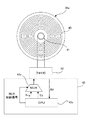
図1には本発明のジンバル装置及びそれを用いた姿勢検出装置の概略構成図、図2には内側電気接続部の一方の円盤ユニットの概略構成図、図3には内側電気接続部を介した通信の一例を示す説明図が示されており、以下これらの図に基づき説明する。なお、図示されている各部の寸法は説明の便宜上一部拡大されており、実際の寸法と異なっている場合もある。 FIG. 1 is a schematic configuration diagram of the gimbal device of the present invention and a posture detection device using the gimbal device, FIG. 2 is a schematic configuration diagram of one disk unit of the inner electrical connection portion, and FIG. 3 is an inner electrical connection portion. Explanatory diagrams showing an example of the communication are shown, and will be described below based on these diagrams. The dimensions of each part shown are partially enlarged for convenience of explanation, and may differ from the actual dimensions.
図1に示す姿勢検出装置1は、2軸のジンバル装置2を介して水平を検出するための傾斜検出ユニット10(水平検出部)が設けられている。
The
詳しくは、傾斜検出ユニット10は部品支持部11に支持されており、当該部品支持部11は矩形枠形状の内フレーム12内にて第1の軸A1を回転軸として回転自在に支持され、当該内フレーム12は矩形枠形状の外フレーム13内にて第2の軸A2を回転軸として回転自在に支持されている。第1の軸A1及び第2の軸A2は直交しており、姿勢検出装置1を水平面上に設置した場合に、いずれも水平となる軸である。なお、部品支持部11と内フレーム12との間は一対の第1のスラストベアリング14、14が介在し、内フレーム12と外フレーム13との間は一対の第2のスラストベアリング15、15がそれぞれ介在している。
Specifically, the
傾斜検出ユニット10は、チルトセンサ20、加速度センサ21、及びセンサ制御部22を有している。チルトセンサ20は加速度センサ21よりも高精度に水平を検出するものであり、例えば水平液面に検出光を入射させ反射光の反射角度の変化で水平を検出する傾斜検出器、又は封入した気泡の位置変化で傾斜を検出する気泡管である。加速度センサ21は例えば6軸加速度センサであり、チルトセンサ20よりも傾斜変化を高応答性で検出するものである。センサ制御部22は、チルトセンサ20及び加速度センサ21を制御する回路を有し、チルトセンサ20及び加速度センサ21で検出された情報を処理する。なお、傾斜検出ユニットにおけるセンサ類は傾斜を検出できるセンサであればよく、例えば角速度センサ等のその他の慣性計測センサを用いてもよい。
The
内フレーム12の一辺には第1の軸A1を回転軸とする第1のモータ30が設けられている。第1のモータ30はステータ30aが内フレーム12に設けられており、モータ回転軸30bを含むロータ側が部品支持部11に連結されている。
A
また、内フレーム12の同辺には、第1のエンコーダ31が設けられている。当該第1のエンコーダ31は、内フレーム12側にリードヘッド31aが設けられ、部品支持部11側に当該部品支持部11と同期回転するコードホイール31bが設けられており、リードヘッド31aがコードホイール31bの回転角度に応じた位置の信号を受信することで回転角度を検出するアブソリュート形エンコーダである。なお、エンコーダの形式はアブソリュート形エンコーダに限られず、例えばインクリメンタル形エンコーダであってもよい。
Further, a
また、内フレーム12には、第1のモータ30及び第1のエンコーダ31が設けられている辺とは異なる辺に、第2の軸A2を回転軸とする第2のモータ32と第2のエンコーダ33が設けられている。
Further, the
第2のモータ32はステータ32aが内フレーム12に設けられており、モータ回転軸32bを含むロータ側が外フレーム13に連結されている。
In the
第2のエンコーダ33は、第1のエンコーダ31と同様にアブソリュート形エンコーダであり、内フレーム12側にリードヘッド33aが、外フレーム13側にコードホイール33bが設けられている。
The
また、内フレーム12において第1のモータ30及び第1のエンコーダ31が設けられている辺と対向する辺と部品支持部11との間には、第1の軸A1回りの回転を許容しつつ非接触な電気的接続を行う内側電気接続部34が設けられている。さらに、内フレーム12において第2のモータ32及び第2のエンコーダ33が設けられている辺と対向する辺と外フレーム13との間には、第2の軸A2回りの回転を許容しつつ非接触な電気的接続を行う外側電気接続部35が設けられている。
Further, in the
内側電気接続部34及び外側電気接続部35は、同軸上に隙間を有して対向して配置された一対の円盤ユニット34a、34b、35a、35bからなる。
The inner
詳しくは、図2に一つの円盤ユニット34aの対向面が示されており、同図に示すように、円盤ユニット34aはフェライト等の磁性材料からなり、その対向面には、第1の軸A1回りに給電コイル40(無線給電部)が径方向に巻回され、軸心部分には光ファイバ41(無線通信部)が第1の軸A1と同軸上に配設されている。なお、他の円盤ユニット34b、35a、35bも同様の構成をなしており、説明を省略する。
Specifically, FIG. 2 shows the facing surface of one
このような構成により、一対の円盤ユニット34a、34b、35a、35bの一方の給電コイル40に通電すると、相互誘導作用により他方の円盤ユニット34a、34b、35a、35bの給電コイル40に電力が発生し、円盤ユニット間でのいわゆる無線給電が可能である。また、一対の円盤ユニット34a、34b、35a、35bのそれぞれの光ファイバ41は同軸上に配置され先端が対向しており、一方の光ファイバ42の信号は他方の光ファイバ41に導光され、円盤ユニット間でのいわゆる無線通信が可能である。
With such a configuration, when one of the feeding coils 40 of the pair of
このような一対の円盤ユニット34a、34b、35a、35bからなる内側電気接続部34及び外側電気接続部35は、給電コイル40は回転軸回りに巻回されており、光ファイバ41は回転軸上に配置されていることから、いずれも回転の影響を受けることなく、無線給電及び無線通信という非接触な電気的接続を実現可能である。
In the inner
なお、光ファイバ41は、例えば受光及び発光の各光半導体と樹脂モールドレンズを備えた光リンク用のフォトIC42の光軸へ導光するよう配設され、当該フォトIC42により一対の円盤ユニット34a、34b、35a、35b間の通信を制御するのが好ましい。
The
図2に示されるように、円盤ユニットに設けられる光ファイバ41は1本であるため、内側電気接続部34及び外側電気接続部35を介する通信はシリアル通信となる。そこで、本実施形態では、フォトIC42にマルチプレクサ(MUX)43aを含む光通信制御部43が接続されている。
As shown in FIG. 2, since the number of
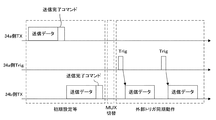
光通信制御部43は、受信信号RXがフォトIC42からCPU43bに直接伝達される一方で、送信信号TXはMUX43aを介してフォトIC42に伝達される。またCPU43bからはMUX43aを介してトリガ信号Trigが送信可能であるとともに、MUX43aからフォトIC42に送られる信号を送信信号TX及びトリガ信号Trigの間で切り替えるためのMUX制御信号が送信可能である。このようなフォトIC42及び光通信制御部43が各円盤ユニット34a、34b、35a、35bに対応して設けられている。
In the optical
ここで図3を参照すると、内側電気接続部34の一対の円盤ユニット34a、34b間の通信例が示されており、同図に基づきMUX43aを用いた一対の円盤ユニット34a、34b間の通信手法について説明する。
Here, referring to FIG. 3, an example of communication between the pair of
図3に示すように、初期設定等では、一方の円盤ユニット34a側及び他方の円盤ユニット34b側で送信データを送るタイミングをずらした半二重通信を行う。そして、一対の円盤ユニット34a、34b間の同期が完了した後は、受け取り側となる一方の円盤ユニット34aはMUX43aをトリガ信号Trig側に切り替える。これにより、これ以降は一方の円盤ユニット34aからトリガ信号Trigが送信されるのに応じて、他方の円盤ユニット34bから送信データが送信され、トリガ信号Trigに同期したタイミングでの姿勢検出を行いながら、送信完了コマンドを送らずに済む円滑なデータ通信を行うことが可能となる。
As shown in FIG. 3, in the initial setting and the like, half-duplex communication is performed on one
図1に戻り、姿勢検出装置1はジンバル装置2外の外部装置3と接続されている。当該外部装置3は、例えば他の制御部や電源を備えたものであり、ジンバル装置2内のセンサ制御部22、第1のモータ30、第1のエンコーダ31、第2のモータ32、及び第2のエンコーダ33への電力供給が可能であるとともに、センサ制御部22と相互に通信が可能である。
Returning to FIG. 1, the
詳しくは、外部装置3から延びる電気導線及び通信導線(以下、まとめて配線と称し、一本の線として図示する)は外側電気接続部35の外フレーム13側の円盤ユニット35aに接続されている。
Specifically, the electric wire and the communication wire extending from the external device 3 (hereinafter collectively referred to as wiring and shown as one wire) are connected to the
内フレーム12には各モータ30、32及び各エンコーダ31、33の制御を行うモータ制御部36が設けられており、外側電気接続部35の内フレーム12側の円盤ユニット35bから当該モータ制御部36に配線51が延びている。さらに当該モータ制御部36から、第1のモータ30及び第1のエンコーダ31、並びに第2のモータ32及び第2のエンコーダ33へと、内フレーム12に沿ってそれぞれ配線52、53が延びている。また、モータ制御部36は内側電気接続部34の内フレーム12側の円盤ユニット34aと接続されており、部品支持部11側の円盤ユニット34bからはセンサ制御部22まで配線54が延びている。
The
このように構成された姿勢検出装置1は、予め外フレーム13が水平に設置された場合にチルトセンサ20及び加速度センサ21が水平を検出するように設定され、さらに第1のエンコーダ31及び第2のエンコーダ33の出力が共に基準位置(回転角0°)を示すように設定される。
The
そして、姿勢検出装置1が水平ではない他の場所に設置されたときには、傾斜検出ユニット10のセンサ制御部22がチルトセンサ20及び加速度センサ21により水平を検出するよう、即ち部品支持部11が水平姿勢を維持するように、モータ制御部36を介して第1のモータ30及び第2のモータ32により整準を行う。つまり、第1のモータ30により部品支持部11の第1の軸A1回りの角度を調整し、第2のモータ32により部品支持部11の第2の軸A2回りの角度を調整する。
Then, when the
そして、部品支持部11が水平姿勢となったときに、センサ制御部22は、第1のエンコーダ31により検出される第1の軸A1回りの角度、第2のエンコーダ33により検出される第2の軸A2回りの角度をそれぞれ取得することで、外フレーム13の水平に対する姿勢、即ち姿勢検出装置1の水平に対する姿勢を検出する。センサ制御部22はこの検出した姿勢情報を外部装置3に出力可能である(姿勢検出部)。
Then, when the
以上のように姿勢検出装置1が備えるジンバル装置2は、部品支持部11と内フレーム12との間、内フレーム12と外フレーム13との間のそれぞれの電気的接続が、回転を許容しつつ非接触な内側電気接続部34及び外側電気接続部35により接続され、当該内側電気接続部34及び外側電気接続部35を介して外フレーム13から部品支持部11まで配線50〜54が敷設されている。
As described above, in the
これにより配線50〜54が回転体である部品支持部11、内フレーム12、外フレーム13の間を跨ることはないことから、各回転体11、12、13は拘束されることなく確実に360°以上の回転を行うことができる。そして、内側電気接続部34及び外側電気接続部35は非接触な電気的接続手段であることから、スリップリングのような摩擦や摩耗に起因する問題を生じることなく、信頼性の高い回転体間の電気接続を実現し、且つ回転体の回転応答性の向上及び回転抵抗の低減を実現することができる。
As a result, the wirings 50 to 54 do not straddle between the
特に、内側電気接続部34及び外側電気接続部35は、一対の円盤ユニット34a、34b、35a、35bの対向面に給電コイル40を巻回した簡易な構成で相互誘電作用を利用した無線給電を行うことができ、且つ、回転軸心に光ファイバ41を配設した簡易な構成で無線通信を行うことができる。このように内側電気接続部34及び外側電気接続部35は、一対の円盤ユニット34a、34b、35a、35bによる簡易な構成で、無線給電と無線通信を両立した非接触な電気的接続を実現することができる。
In particular, the inner
また、第1のモータ30及び第2のモータ32は、いずれもステータ30a、32aが内フレーム12に設けられており、当該第1のモータ30及び第2のモータ32への配線52、53は内フレーム12に沿って敷設されることから、部品支持部11及び内フレーム12の回転制御可能なジンバル装置2としても、回転体間を跨ぐことなく配線を敷設することができる。
Further, in both the
さらに、ジンバル装置2は、部品支持部11に傾斜検出ユニット10を設け、第1のモータ30及び第2のモータ32に対応した第1のエンコーダ31及び第2のエンコーダ33を設けて、姿勢検出を可能としている。これにより、信頼性及び応答性の高い姿勢検出を実現することができる。
Further, the
このような姿勢検出装置1及びジンバル装置2は種々の装置に適用することが可能である。
Such a
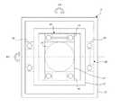
例えば、図4には、上記実施形態の姿勢検出装置1を搭載した測量装置60が示されている。
For example, FIG. 4 shows a
図4に示すように、測量装置60は、姿勢検出装置1とともに、少なくとも、光波を用いて測距する光波距離計61と、測量を制御する測量制御部62とを備えており、各部が相互に通信可能である。当該測量装置60は、光波距離計61により測距を行うと同時に、姿勢検出装置1により測量装置60の姿勢を検出し、測量制御部62がこれらの測距情報及び姿勢情報を統合して測量結果を出力する。
As shown in FIG. 4, the surveying
このように、測量装置60に姿勢検出装置1を適用することで、測量装置60単体で信頼性及び応答性の高い測量を実現することができる。
By applying the
また、本実施例の測量装置は光波距離計を有する測量装置で記載したが、衛星信号により位置情報を得るGPS(Global Positioning System)等のGNSS(Global Navigation Satellite System)装置に適用しても良い。 Further, although the surveying device of this embodiment is described as a surveying device having a light wave range finder, it may be applied to a GNSS (Global Navigation Satellite System) device such as GPS (Global Positioning System) that obtains position information by satellite signals. ..
例えば、図4の光波距離計61に代えて、GPS(測位部)を設けてもよい。この場合測量制御部62は、GPSにより測位した位置情報と、姿勢検出装置1により検出される姿勢情報から測量結果を出力する。又は、GPSのアンテナ部を本発明のジンバル装置の部品支持部に設けることで、位置情報及び姿勢情報を取得する構成としてもよい。
For example, a GPS (positioning unit) may be provided instead of the
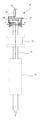
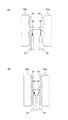
次に、図5には本発明のジンバル装置2’を搭載した測量用ポール70が示され、図6には図5のA−A線に沿う断面図が示されている。
Next, FIG. 5 shows a
図5に示すように測量用ポール70は、ジンバル装置2’とともに、竿部材71と、反射プリズム72と、マーキング機構73とを有している。図6に示すように、ジンバル装置2’は、部品支持部11’が竿部材71の上部と一体をなしており、当該部品支持部11’は内フレーム12’内にて第1の軸A1’を回転軸として回転自在に支持され、内フレーム12’は外フレーム13’内にて第2の軸A2’を回転軸として回転自在に支持されている。なお、部品支持部11’と内フレーム12’との間は一対の第1のスラストベアリング14’、14’が介在し、内フレーム12’と外フレーム13’との間は一対の第2のスラストベアリング15’、15’がそれぞれ介在している。
As shown in FIG. 5, the
また、部品支持部11’と内フレーム12’との間には、第1の軸A1’回りの回転を許容しつつ非接触な電気的接続を行う内側電気接続部34’が設けられ、内フレーム12’と外フレーム13’との間には、第2の軸A2’回りの回転を許容しつつ非接触な電気的接続を行う外側電気接続部35’が設けられている。 Further, an inner electrical connection portion 34'that allows non-contact electrical connection while allowing rotation around the first axis A1'is provided between the component support portion 11'and the inner frame 12'. An outer electrical connection 35'is provided between the frame 12'and the outer frame 13'to allow non-contact electrical connection while allowing rotation around the second axis A2'.
そして、外フレーム13’の上面には把持部74が立設されており、当該把持部74の先端には押ボタン75が設けられている。当該押ボタン75から延びる配線76は、把持部74から外フレーム13’、外側電気接続部35’、内フレーム12’、内側電気接続部34’、部品支持部11’、竿部材71を介して、マーキング機構73まで敷設されている。
A
このように構成された測量用ポール70は、測量者が当該把持部74を把持すると、ジンバル装置2’に支持される竿部材71は自重により鉛直方向に垂下する。そして、図示しない測量機からの測定光を反射プリズム72が反射することで、当該測量用ポールの位置が検出される。さらに、測点にて竿部材71の先端を押し付けるように測量者が把持部74を押し下げ、押ボタン75を押下すると、マーキング機構73が作動して当該測点にマーキングを行う。
When the surveyor grips the
このように、測量用ポール70にジンバル装置2’を適用することで、測量用ポール70の竿部材71を軽量としても確実に垂下させることができ、且つ信頼性及び応答性の高いマーキング作業を行うことができる。
By applying the gimbal device 2'to the
次に図7には、本発明のジンバル装置2’’を搭載した無人飛行移動体(UAV:Unmanned Air Vehicle)80が示されている。
Next, FIG. 7 shows an unmanned air vehicle (UAV) 80 equipped with the
図7に示すようにUAV80は、ジンバル装置2’’とともに、飛行機構81と、カメラ82とを有している。ジンバル装置2’’は上記測量用ポール70に適用したジンバル装置2’’と同様の基本構成をなしており、外フレーム13’’の上面に飛行機構81が接続されており、部品支持部11’’にカメラ82(撮影部)が設けられている。これにより、ジンバル装置2’’は、飛行機構81の飛行姿勢に関わらず、カメラ82を常に下方に指向させることができる。
As shown in FIG. 7, the
そして、飛行機構81から延びる配線83は、外フレーム13’’、外側電気接続部35’’(図示せず)、内フレーム12’’、内側電気接続部34’’(図示せず)、部品支持部11’’、を介して、カメラ82まで敷設されている。
The
このようにUAV80にジンバル装置2’’を適用することで、飛行機構81の飛行姿勢に関わらず、信頼性及び応答性高くカメラ82による撮影を行うことができることができる。
By applying the
以上で本発明の実施形態の説明を終えるが、本発明の態様はこの実施形態に限定されるものではない。 Although the description of the embodiment of the present invention is completed above, the aspect of the present invention is not limited to this embodiment.
上記実施形態における姿勢検出装置1では、傾斜検出ユニット10のセンサ制御部22が、水平の検出からモータ駆動の指示、エンコーダによる角度検出情報の取得、姿勢検出等を取りまとめて行っているが、これらの各制御はセンサ制御部のみで行うのに限らず、例えば、モータ制御部や外部装置が行ってよいし、制御を分担してもよい。
In the
また、上記実施形態におけるジンバル装置2、2’、2’’は2軸のジンバル装置であるが3軸以上のジンバル装置としてもよい。
Further, although the
また、上記実施形態におけるジンバル装置2は、部品支持部11、内フレーム12、外フレーム13がいずれも矩形状をなしているが、この形状に限られるものではなく、円形状や、コの字状の枠体であってもよい。
Further, in the
また、上記実施形態における内側電気接続部34及び外側電気接続部35は、一対の円盤ユニット34a、34b、35a、35bに給電コイル40を巻回した無線給電及び光ファイバ41による無線通信を用いることで簡易な構成で回転を許容した非接触な電気的接続を実現しているが、電磁誘導、磁界共鳴、電界共鳴、静電容量結合等の他の手法による非接触な電気的接続を実現してもよい。
Further, the inner
例えば、図8には、内側電気接続部及び外側電気接続部の第1変形例(a)及び第2変形例(b)の概略構成図が示されている。 For example, FIG. 8 shows a schematic configuration diagram of a first modification (a) and a second modification (b) of the inner electrical connection portion and the outer electrical connection portion.
図8(a)に示す第1変形例の電気接続部90は、一対の円盤ユニット90a、90bの対向面に回転軸回り給電コイル91が径方向に巻回されている。さらに、各円盤ユニット90a、90bの対向面には光ファイバ92が径方向に沿って延び、先端が軸心に指向している。そして、各円盤ユニット90a、90bの軸心にはミラー93が設けられている。
In the electrical connection portion 90 of the first modification shown in FIG. 8A, a rotation axis
ミラー93と光ファイバ92は円盤ユニット90a、90bの回転の影響を受けないよう配置されており、ミラー93は径方向に照射される光ファイバ92の光を回転軸方向に反射するよう傾斜している。
The
また、図8(b)に示す第2変形例の電気接続部90’は給電コイル91’、光ファイバ92’、ミラー93’の配置は第1変形例と同じであるが光ファイバ92’の先端形状とミラー93’の形状が異なっている。 Further, in the electrical connection portion 90'of the second modification shown in FIG. 8B, the arrangement of the feeding coil 91', the optical fiber 92', and the mirror 93' is the same as that of the first modification, but the optical fiber 92' The shape of the tip and the shape of the mirror 93'are different.
第2変形例の光ファイバ92’は、光線が円盤ユニット側に屈曲するよう傾斜している。それに対してミラー93’は、第1変形例のミラー93よりも対向面に対する傾斜角度が浅く、対向面に対する突出量が減少されている。したがって、第2変形例の電気接続部90’は、一対の円盤ユニット90a’、90b’の間隔をより狭くすることができる。
The optical fiber 92'of the second modification is inclined so that the light beam bends toward the disk unit. On the other hand, the mirror 93'has a shallower inclination angle with respect to the facing surface than the
1 姿勢検出装置
2 ジンバル装置
3 外部装置
10 傾斜検出ユニット(水平検出部)
11 部品支持部
12 内フレーム
13 外フレーム
20 チルトセンサ
21 加速度センサ
22 センサ制御部(姿勢検出部)
30 第1のモータ
31 第1のエンコーダ
32 第2のモータ
33 第2のエンコーダ
34 内側電気接続部
35 外側電気接続部
34a、34b、35a、35b 円盤ユニット
40 給電コイル(無線給電部)
41 光ファイバ(無線通信部)
1
11 Parts support 12
30
41 Optical fiber (wireless communication unit)
Claims (9)
前記部品を支持する部品支持部と、
前記部品支持部を第1の軸を回転軸として回転自在に支持する内フレームと、
前記内フレームを第2の軸を回転軸として回転自在に支持する外フレームと、
前記部品支持部と前記内フレームとの間にて、前記第1の軸回りの回転を許容しつつ非接触な電気的接続を行う内側電気接続部と、
前記内フレームと前記外フレームとの間にて、前記第2の軸回りの回転を許容しつつ非接触な電気的接続を行う外側電気接続部と、
前記内側電気接続部及び前記外側電気接続部を介して、前記部品から前記外フレームまで敷設された配線と、
を備え、
前記内側電気接続部及び前記外側電気接続部は、回転軸と同軸上にて先端が対向した一対の光ファイバを含む、ジンバル装置。 A gimbal device that rotatably supports a predetermined component in at least two axes.
A component support part that supports the component and
An inner frame that rotatably supports the component support portion with the first axis as a rotation axis, and
An outer frame that rotatably supports the inner frame with the second axis as a rotation axis, and
An inner electrical connection portion that makes a non-contact electrical connection between the component support portion and the inner frame while allowing rotation around the first axis.
An outer electrical connection portion that makes a non-contact electrical connection between the inner frame and the outer frame while allowing rotation around the second axis.
Wiring laid from the component to the outer frame via the inner electrical connection and the outer electrical connection, and
Equipped with a,
The inner electrical connection portion and the outer electrical connection portion are gimbal devices including a pair of optical fibers whose tips are opposed to each other on the same axis as the rotation axis .
前記外フレームに対して前記内フレームを前記第2の軸回りに回転駆動する第2のモータと、を備え、
前記第1のモータ及び第2のモータへの配線は、前記部品から前記外フレームまで敷設された配線のうち前記内フレームに沿って敷設される部分に含まれる請求項1または2に記載のジンバル装置。 A first motor that rotationally drives the component support portion around the first axis with respect to the inner frame, and
A second motor that rotationally drives the inner frame around the second axis with respect to the outer frame is provided.
The gimbal according to claim 1 or 2 , wherein the wiring to the first motor and the second motor is included in a portion of the wiring laid from the component to the outer frame that is laid along the inner frame. apparatus.
さらに、前記部品として前記部品支持部に設けられ、水平を検出する水平検出部と、
前記部品支持部に対する前記内フレームの前記第1の軸回りの角度を検出する第1のエンコーダと、
前記内フレームに対する前記外フレームの前記第2の軸回りの角度を検出する第2のエンコーダと、
前記第1のモータ及び第2のモータを駆動して、前記水平検出部により水平が検出される状態として、第1のエンコーダ及び第2のエンコーダにより検出された角度を取得することで、外フレームの水平に対する姿勢を検出する姿勢検出部と、
を備える姿勢検出装置。 The gimbal device according to any one of claims 1 to 4 is provided.
Further, a horizontal detection unit provided on the component support portion as the component to detect the horizontal, and a horizontal detection unit
A first encoder that detects an angle around the first axis of the inner frame with respect to the component support portion, and
A second encoder that detects the angle around the second axis of the outer frame with respect to the inner frame, and
The outer frame is obtained by driving the first motor and the second motor and acquiring the angles detected by the first encoder and the second encoder in a state where the horizontal is detected by the horizontal detection unit. A posture detector that detects the horizontal posture of the
Posture detection device.
光波を用いて測距する光波距離計と、
前記光波距離計により測距した測距情報と、前記姿勢検出装置により検出される姿勢情報から測量結果を出力する測量制御部と、
を備える測量装置。 The posture detection device according to claim 5 and
A laser rangefinder that measures distance using light waves,
A survey control unit that outputs survey results from the distance measurement information measured by the light wave range finder and the attitude information detected by the attitude detection device.
A surveying device equipped with.
衛星信号により位置情報を得る測位部と、
前記測位部により測位した位置情報と、前記姿勢検出装置により検出される姿勢情報から測量結果を出力する測量制御部と、
を備える測量装置。 A posture detection device of claim 5,
A positioning unit that obtains position information from satellite signals,
A survey control unit that outputs survey results from the position information measured by the positioning unit and the attitude information detected by the attitude detection device.
A surveying device equipped with.
前記ジンバル装置の部品支持部に連結され、自重により鉛直方向に垂下する竿部材と、
前記竿部材に設けられた反射プリズムと、
を備える測量用ポール。 The gimbal device according to any one of claims 1 to 4 ,
A rod member that is connected to the component support of the gimbal device and hangs vertically due to its own weight.
A reflective prism provided on the rod member and
Surveying pole with.
前記ジンバル装置の外フレームに連結され、飛行可能な飛行機構と、
前記ジンバル装置の部品支持部に設けられ、撮影を行う撮影部と、
を備える飛行移動体。
The gimbal device according to any one of claims 1 to 4 ,
A flight mechanism that is connected to the outer frame of the gimbal device and can fly,
An imaging unit provided on the component support portion of the gimbal device and performing imaging,
Flying mobile with.
Priority Applications (1)
| Application Number | Priority Date | Filing Date | Title |
|---|---|---|---|
| JP2017032977A JP6830375B2 (en) | 2017-02-24 | 2017-02-24 | Gimbal device, attitude detector, surveying device, surveying pole, and flying vehicle |
Applications Claiming Priority (1)
| Application Number | Priority Date | Filing Date | Title |
|---|---|---|---|
| JP2017032977A JP6830375B2 (en) | 2017-02-24 | 2017-02-24 | Gimbal device, attitude detector, surveying device, surveying pole, and flying vehicle |
Publications (2)
| Publication Number | Publication Date |
|---|---|
| JP2018138874A JP2018138874A (en) | 2018-09-06 |
| JP6830375B2 true JP6830375B2 (en) | 2021-02-17 |
Family
ID=63450850
Family Applications (1)
| Application Number | Title | Priority Date | Filing Date |
|---|---|---|---|
| JP2017032977A Active JP6830375B2 (en) | 2017-02-24 | 2017-02-24 | Gimbal device, attitude detector, surveying device, surveying pole, and flying vehicle |
Country Status (1)
| Country | Link |
|---|---|
| JP (1) | JP6830375B2 (en) |
Family Cites Families (7)
| Publication number | Priority date | Publication date | Assignee | Title |
|---|---|---|---|---|
| JP2002281694A (en) * | 2001-03-16 | 2002-09-27 | Tamagawa Seiki Co Ltd | Spatial stabilizer |
| US6763595B1 (en) * | 2002-06-21 | 2004-07-20 | Pls - Pacific Laser Systems | Laser-based tool for indicating level, plumb and square |
| JP4284496B2 (en) * | 2003-01-14 | 2009-06-24 | 多摩川精機株式会社 | Space stabilizer |
| JP5385604B2 (en) * | 2008-12-25 | 2014-01-08 | 株式会社トプコン | Optical signal transmission device |
| JP5707209B2 (en) * | 2011-04-08 | 2015-04-22 | 株式会社トプコン | Surveying pole |
| JP6151902B2 (en) * | 2012-09-20 | 2017-06-21 | 株式会社トプコン | Camera for photo measurement and aerial photographic equipment |
| JP6541365B2 (en) * | 2015-02-16 | 2019-07-10 | 株式会社トプコン | Posture detection device and data acquisition device |
-
2017
- 2017-02-24 JP JP2017032977A patent/JP6830375B2/en active Active
Also Published As
| Publication number | Publication date |
|---|---|
| JP2018138874A (en) | 2018-09-06 |
Similar Documents
| Publication | Publication Date | Title |
|---|---|---|
| US9609282B2 (en) | Camera for photogrammetry and aerial photographic device | |
| EP3205977B1 (en) | Flight plan preparing method and flying vehicle guiding system | |
| JP5882951B2 (en) | Aircraft guidance system and aircraft guidance method | |
| JP6326237B2 (en) | Measuring system | |
| CN108443680B (en) | Mobile device, mobile device control system and control method | |
| CN111226090A (en) | Laser tracker with improved roll angle measurement | |
| US10800344B2 (en) | Aerial photogrammetric device and aerial photogrammetric method | |
| CN104011502B (en) | Automatically the measurement of the level | |
| JP2015113100A (en) | Information acquisition system and unmanned flight body controller | |
| JP6577083B2 (en) | Measuring system | |
| US10481604B2 (en) | High accuracy remote coordinate machine | |
| CN107246869A (en) | A kind of strapdown micro-mechanical inertia navigation system | |
| CN110869787A (en) | Magnetic sensor calibration method and movable platform | |
| JP6830375B2 (en) | Gimbal device, attitude detector, surveying device, surveying pole, and flying vehicle | |
| US20150316376A1 (en) | Non-contacting electro-magnetic spherical planar motor providing 3-axis control of a ball joint gimbal mounted electro-optic system | |
| JP6763749B2 (en) | Mobile control system and mobile | |
| JP2018054408A (en) | Surveying equipment | |
| JP2018138922A (en) | Measuring system | |
| CA2783767C (en) | Measuring device | |
| RU2544295C1 (en) | Gyrocompass | |
| JP2019117993A (en) | Radio control device and radio control system | |
| JPH0984161A (en) | Two-way wireless communication method between fixed station and mobile station | |
| JP2015141163A (en) | position measuring system | |
| WO1998046967A2 (en) | Relative rate sensor for control moment gyroscopes |
Legal Events
| Date | Code | Title | Description |
|---|---|---|---|
| A621 | Written request for application examination |
Free format text: JAPANESE INTERMEDIATE CODE: A621 Effective date: 20191202 |
|
| A977 | Report on retrieval |
Free format text: JAPANESE INTERMEDIATE CODE: A971007 Effective date: 20201002 |
|
| A131 | Notification of reasons for refusal |
Free format text: JAPANESE INTERMEDIATE CODE: A131 Effective date: 20201027 |
|
| A521 | Request for written amendment filed |
Free format text: JAPANESE INTERMEDIATE CODE: A523 Effective date: 20201217 |
|
| TRDD | Decision of grant or rejection written | ||
| A01 | Written decision to grant a patent or to grant a registration (utility model) |
Free format text: JAPANESE INTERMEDIATE CODE: A01 Effective date: 20210105 |
|
| A61 | First payment of annual fees (during grant procedure) |
Free format text: JAPANESE INTERMEDIATE CODE: A61 Effective date: 20210126 |
|
| R150 | Certificate of patent or registration of utility model |
Ref document number: 6830375 Country of ref document: JP Free format text: JAPANESE INTERMEDIATE CODE: R150 |
|
| R250 | Receipt of annual fees |
Free format text: JAPANESE INTERMEDIATE CODE: R250 |
|
| R250 | Receipt of annual fees |
Free format text: JAPANESE INTERMEDIATE CODE: R250 |
|
| R250 | Receipt of annual fees |
Free format text: JAPANESE INTERMEDIATE CODE: R250 |