JP6830793B2 - A driving jig used when driving a support foundation member and the support support foundation member into the ground. - Google Patents
A driving jig used when driving a support foundation member and the support support foundation member into the ground. Download PDFInfo
- Publication number
- JP6830793B2 JP6830793B2 JP2016215057A JP2016215057A JP6830793B2 JP 6830793 B2 JP6830793 B2 JP 6830793B2 JP 2016215057 A JP2016215057 A JP 2016215057A JP 2016215057 A JP2016215057 A JP 2016215057A JP 6830793 B2 JP6830793 B2 JP 6830793B2
- Authority
- JP
- Japan
- Prior art keywords
- driving
- strut
- foundation member
- support
- foundation
- Prior art date
- Legal status (The legal status is an assumption and is not a legal conclusion. Google has not performed a legal analysis and makes no representation as to the accuracy of the status listed.)
- Active
Links
- 238000003780 insertion Methods 0.000 claims description 84
- 230000037431 insertion Effects 0.000 claims description 84
- 239000004576 sand Substances 0.000 claims description 30
- 229910000831 Steel Inorganic materials 0.000 description 39
- 239000010959 steel Substances 0.000 description 39
- 238000003825 pressing Methods 0.000 description 23
- 238000000034 method Methods 0.000 description 6
- 238000010276 construction Methods 0.000 description 5
- 229910052751 metal Inorganic materials 0.000 description 5
- 239000002184 metal Substances 0.000 description 5
- 230000002093 peripheral effect Effects 0.000 description 3
- 230000001681 protective effect Effects 0.000 description 3
- 239000013049 sediment Substances 0.000 description 3
- 229910052782 aluminium Inorganic materials 0.000 description 2
- XAGFODPZIPBFFR-UHFFFAOYSA-N aluminium Chemical compound [Al] XAGFODPZIPBFFR-UHFFFAOYSA-N 0.000 description 2
- 230000000694 effects Effects 0.000 description 2
- 238000000465 moulding Methods 0.000 description 2
- 238000004080 punching Methods 0.000 description 2
- 229910001220 stainless steel Inorganic materials 0.000 description 2
- 239000010935 stainless steel Substances 0.000 description 2
- 230000004888 barrier function Effects 0.000 description 1
- 239000000463 material Substances 0.000 description 1
- 239000004570 mortar (masonry) Substances 0.000 description 1
- 238000010422 painting Methods 0.000 description 1
- 238000007747 plating Methods 0.000 description 1
- 230000000630 rising effect Effects 0.000 description 1
- 239000002689 soil Substances 0.000 description 1
- XLYOFNOQVPJJNP-UHFFFAOYSA-N water Substances O XLYOFNOQVPJJNP-UHFFFAOYSA-N 0.000 description 1
Images


Landscapes
- Foundations (AREA)
Description
本発明は、主として防護柵、防音壁、標識柱等の道路付帯設備に用いられる支柱や、フェンスの支柱、車止めなどに用いられる支柱用基礎部材およびその支柱用基礎部材を地中に打ち込む際に用いる打ち込み治具に関するものである。 INDUSTRIAL APPLICABILITY The present invention is used when driving columns used mainly for road ancillary equipment such as protective fences, noise barriers, sign columns, support columns of fences, foundation members for columns used for vehicle stops, and foundation members for the columns into the ground. It relates to a driving jig to be used.
道路付帯設備の支柱を地面に立設するにおいては、例えば防護柵を設置する場合、通常独立したコンクリートブロックや連続したコンクリート基礎に支柱の一部を埋設したり、支柱の一部を直接地面に打ち込んで埋設したりして形成している。この内、支柱の一部を埋設するものでは、歩道と歩道の外との境界に設置される歩行者自転車用柵である種別Pの防護柵において、非特許文献1に支柱埋込みの必要深さが示されており、種別Pの横断抑止用に設置される防護柵では、1000mmまたは1200mmの埋込み深さが必要であると示されている。(非特許文献1)。
When erection of pillars of road ancillary equipment on the ground, for example, when installing a guard fence, a part of the pillar is usually buried in an independent concrete block or a continuous concrete foundation, or a part of the pillar is directly placed on the ground. It is formed by driving it in and burying it. Among these, in the case of burying a part of the support, the required depth of support in Non-Patent
しかしながら、この様に支柱を埋め込む場合、市街地等においては、地中に埋設されているガス管、水道管等の地中埋設物があり、支柱の埋め込み深さを上述の1000mmまたは1200mmを確保することができないことがある。 However, when embedding columns in this way, in urban areas and the like, there are underground objects such as gas pipes and water pipes buried in the ground, and the embedding depth of the columns is secured to 1000 mm or 1200 mm as described above. Sometimes you can't.
そこで本発明は、上記の如き課題に鑑みてなされたものであり、支柱の埋め込み深さを深く取れない場所においても、道路付帯設備を設置することができる支柱用基礎部材およびその支柱用基礎部材を地中に打ち込む際に用いる打ち込み治具を提供せんとするものである。 Therefore, the present invention has been made in view of the above-mentioned problems, and is a support base member capable of installing road ancillary equipment even in a place where the embedding depth of the support cannot be obtained deeply, and a support base member thereof. It is intended to provide a driving jig to be used when driving the vehicle into the ground.
上記目的を達成するために、本発明は次のような構成としている。
すなわち、本発明に係る支柱用基礎部材は、縦板部から側方に向けて支柱保持部が延設され、該支柱保持部の先端には、前記支柱保持部の基端に設けられた挿通孔に挿入され係合される係合部が設けられており、前記係合部は縦板状に形成され、前記挿通孔は前記係合部が挿入可能な形状に形成されており、前記挿通孔に挿入されて該挿通孔に係合された前記係合部が前記縦板部に沿って配置されるように形成されていることを特徴とするものである。
また、縦板部から側方に向けて支柱保持部が延設され、該支柱保持部の先端には、前記支柱保持部の基端に設けられた挿通孔に挿入され係合される係合部が設けられており、前記係合部は縦板状に形成され、前記挿通孔は前記係合部が挿入可能な形状に形成されており、前記支柱保持部が構成する筒の内側方向から前記挿通孔に挿入されて係合された前記係合部が前記縦板部に沿って配置されるように形成されていることを特徴とするものである。
In order to achieve the above object, the present invention has the following configuration.
That is, in the support base member according to the present invention, a support support portion extends laterally from the vertical plate portion, and an insertion provided at the base end of the support support portion is provided at the tip of the support support portion. An engaging portion that is inserted into and engaged with the hole is provided, the engaging portion is formed in a vertical plate shape, and the insertion hole is formed in a shape that allows the engaging portion to be inserted. It is characterized in that the engaging portion inserted into the hole and engaged with the insertion hole is formed so as to be arranged along the vertical plate portion .
Further, a strut holding portion is extended from the vertical plate portion toward the side, and the tip of the strut holding portion is engaged with being inserted into an insertion hole provided at the base end of the strut holding portion. A portion is provided , the engaging portion is formed in a vertical plate shape, the insertion hole is formed in a shape into which the engaging portion can be inserted, and the engaging portion is formed from the inside direction of the cylinder formed by the support column holding portion. It is characterized in that the engaging portion inserted into and engaged with the insertion hole is formed so as to be arranged along the vertical plate portion .
この構成によれば、縦板部から側方に向けて支柱保持部を延設し、該支柱保持部の先端には、前記支柱保持部の基端に設けた挿通孔に挿入し係合する係合部を設けているので、前記支柱用基礎部材を金属製の平板からプレス加工で作成する際、前記係合部と前記挿通孔を抜く金型と、前記支柱保持部を成型する金型とで、前記支柱用基礎部材を作成することができるので、金型コストを抑えて前記支柱用基礎部材を作成することができ、加えて、平板から切り落として廃棄する部分を少なくすることができるので、支柱用基礎部材を効率(歩留り)よく作成することができる。 According to this configuration, the support column holding portion extends laterally from the vertical plate portion, and the tip of the support column holding portion is inserted into and engaged with the insertion hole provided at the base end of the support column holding portion. Since the engaging portion is provided, when the foundation member for the support is created from a metal flat plate by press working, the engaging portion, the mold for removing the insertion hole, and the mold for molding the support holding portion are formed. Since the foundation member for the support can be created by the above, the foundation member for the support can be produced while suppressing the mold cost, and in addition, the portion cut off from the flat plate and discarded can be reduced. Therefore, the foundation member for the support can be efficiently produced (yield).
また本発明に係る支柱用基礎部材は、一方の前記支柱用基礎部材の挿通孔に他方の前記支柱用基礎部材の係合部が挿入され係合され、前記一方の前記支柱用基礎部材の係合部が前記他方の支柱用基礎部材の挿通孔に挿入され係合されて用いられることを特徴とするものである。 Further, in the strut foundation member according to the present invention, the engaging portion of the other strut foundation member is inserted and engaged with the insertion hole of one strut foundation member, and the one strut foundation member is engaged. It is characterized in that the joint portion is inserted into and engaged with the insertion hole of the other support foundation member for use.
この構成によれば、一方の前記支柱用基礎部材の挿通孔に他方の前記支柱用基礎部材の係合部を挿入し係合して、前記一方の前記支柱用基礎部材の係合部を前記他方の支柱用基礎部材の挿通孔に挿入し係合して用いるので、2個の前記支柱用基礎部材を係合させた状態において、一方の前記縦板部の側端縁から他方の前記縦板部の側端縁までの幅、いわゆる見付幅を横方向に広く形成することができ、それによって、支柱を1000mmまたは1200mmと言った地中深くまで埋め込むことなく、支柱を立設するのに必要な土圧を得ることができ、地中に埋設物がある場所であっても道路付帯設備を設置することができる。 According to this configuration, the engaging portion of the other strut foundation member is inserted into and engaged with the insertion hole of the one strut foundation member, and the engaging portion of the one strut foundation member is engaged. Since it is used by inserting it into the insertion hole of the other support base member and engaging it, in a state where the two support support foundation members are engaged, the other vertical plate portion is connected to the side edge of the vertical plate portion. The width to the side edge of the plate, the so-called found width, can be formed wide in the lateral direction, so that the support can be erected without embedding the support as deep as 1000 mm or 1200 mm in the ground. The earth pressure required for the construction can be obtained, and road ancillary equipment can be installed even in places where there are buried objects in the ground.
また本発明に係る支柱用基礎部材は、一方の前記支柱用基礎部材の挿通孔に他方の前記支柱用基礎部材の係合部が挿入され係合され、前記他方の支柱用基礎部材の挿通孔にさらに別の前記支柱用基礎部材の係合部が挿入され係合され、前記一方の支柱用基礎部材の係合部が前記別の支柱用基礎部材の挿通孔に挿入され係合されて用いられることを特徴とするものである。 Further, in the strut foundation member according to the present invention, the engaging portion of the other strut foundation member is inserted and engaged with the insertion hole of one strut foundation member, and the insertion hole of the other strut foundation member is engaged. Another engaging portion of the strut foundation member is inserted and engaged, and the engaging portion of the one strut foundation member is inserted into and engaged with the insertion hole of the other strut foundation member. It is characterized by being able to be.
この構成によれば、一方の前記支柱用基礎部材の挿通孔に他方の前記支柱用基礎部材の係合部が挿入され係合され、前記他方の支柱用基礎部材の挿通孔にさらに別の前記支柱用基礎部材の係合部が挿入され係合され、前記一方の支柱用基礎部材の係合部が前記別の支柱用基礎部材の挿通孔に挿入され係合されて用いるので、見付幅を横方向に広く形成することができ、それによって、支柱を1000mmまたは1200mmと言った地中深くまで埋め込むことなく、支柱を立設するのに必要な土圧を得ることができ、地中に埋設物がある場所であっても道路付帯設備を設置することができるのに加えて、3個の前記支柱用基礎部材を係合させることにより形成される空間に支柱を挿入し、前記支柱保持部と前記支柱との間にモルタル等を充填して固化させると、前記支柱により支持される道路付帯設備等に何らかの衝撃力が横方向から加わった場合、地中に埋設されている前記支柱用基礎部材に対して、どちらの方向から横方向の衝撃力がかかっても、その衝撃力に対して前記支柱用基礎部材が踏ん張りきることができる。 According to this configuration, the engaging portion of the other strut foundation member is inserted and engaged with the insertion hole of the one strut foundation member, and the other strut foundation member is further inserted into the insertion hole of the other strut foundation member. Since the engaging portion of the strut foundation member is inserted and engaged, and the engaging portion of the one strut foundation member is inserted into and engaged with the insertion hole of the other strut foundation member, the found width is used. Can be formed wide in the lateral direction, whereby the earth pressure required for erection of the stanchion can be obtained without burying the stanchion as deep as 1000 mm or 1200 mm in the ground. In addition to being able to install road ancillary equipment even in places where there are buried objects, the columns are inserted into the space formed by engaging the three foundation members for the columns, and the columns are held. When a mortar or the like is filled between the portion and the support and solidified, when some impact force is applied from the lateral direction to the road ancillary equipment or the like supported by the support, the support is buried in the ground. Regardless of which direction the lateral impact force is applied to the foundation member, the strut foundation member can be fully stretched against the impact force.
また本発明に係る支柱用基礎部材は、前記係合部が縦板状に形成され、前記挿通孔は前記係合部が挿入可能な形状に形成されていることを特徴とするものである。 Further, the support base member according to the present invention is characterized in that the engaging portion is formed in a vertical plate shape, and the insertion hole is formed in a shape into which the engaging portion can be inserted.
この構成によれば、前記係合部を縦板状に形成し、前記挿通孔を前記係合部が挿入可能な形状に形成しているので、前記支柱用基礎部材を金属製の平板からプレス加工で作成する際、前記係合部と前記挿通孔を打ち抜く金型と、前記支柱保持部を成型する金型とで、前記支柱用基礎部材を作成することができるので、金型コストを抑えて前記支柱用基礎部材を作成することができ、加えて、平板から切り落として廃棄する部分を少なくすることができるので、支柱用基礎部材を効率(歩留り)よく作成することができる。 According to this configuration, since the engaging portion is formed in the shape of a vertical plate and the insertion hole is formed in a shape into which the engaging portion can be inserted, the base member for the support column is pressed from a metal flat plate. When making by processing, the base member for the support can be made by the mold for punching the engaging portion and the insertion hole and the mold for molding the support support portion, so that the mold cost can be suppressed. In addition, since the portion to be cut off from the flat plate and discarded can be reduced, the support foundation member can be efficiently produced (yield).
また本発明に係る支柱用基礎部材は、前記係合部の基端部側の上部または下部の少なくともいずれか一方が切欠かれて、切欠部が形成されていることを特徴とするものである。 Further, the support base member according to the present invention is characterized in that at least one of the upper portion and the lower portion on the base end portion side of the engaging portion is cut out to form the cutout portion.
この構成によれば、前記係合部の基端部側の上部または下部の少なくともいずれか一方が切欠かれて、切欠部が形成されているので、前記係合部を前記挿通孔に挿入した後、一方の前記支柱用基礎部材を上方または下方に移動させ前記切欠部に前記挿通孔の周辺部を係合することにより、前記支柱用基礎部材を地中に打ち込む際、組んだ複数個の前記支柱用基礎部材に様々な方向から力が作用しても、それぞれの前記支柱用基礎部材同士がしっかりと係合されているので、それぞれの支柱用基礎部材同士がズレるなどして、支柱用基礎部材が変形することなどを抑止することができる。 According to this configuration, at least one of the upper portion and the lower portion of the engaging portion on the base end side is notched to form the notched portion, so that after the engaging portion is inserted into the insertion hole. When the support foundation member is driven into the ground by moving one of the support foundation members upward or downward and engaging the peripheral portion of the insertion hole with the notch portion, the plurality of the above-mentioned assembled members. Even if forces are applied to the strut foundation members from various directions, the strut foundation members are firmly engaged with each other, so that the strut foundation members are displaced from each other, and the strut foundation members are displaced. It is possible to prevent the member from being deformed.
また本発明に係る打ち込み治具は、打ち込み機具を用いて前記支柱用基礎部材を地中に打ち込む際に用いる打ち込み治具であって、前記支柱用基礎部材の前記支柱保持部が構成する筒の内形に対応した基礎部挿入部と、前記打ち込み機具の打ち込み部または該打ち込み部に取付けられる打ち込み補助具の内形に対応した打ち込み部挿入部とを備え、前記基礎部挿入部と前記打ち込み部挿入部とを連結すると共に、前記支柱用基礎部材の前記支柱保持部が構成する筒の上端及び前記打ち込み機具の打ち込み部または前記打ち込み補助具の下端とに当接される連結部を備えてなり、前記連結部の外形は、前記支柱用基礎部材の前記支柱保持部が構成する筒及び前記打ち込み機具の打ち込み部または前記打ち込み補助具の内形より大きく形成されていることを特徴とするものである。 Further, the driving jig according to the present invention is a driving jig used when driving the support base member into the ground using a driving tool, and is a cylinder formed by the support portion of the support base member. The foundation portion insertion portion corresponding to the inner shape and the driving portion of the driving machine or the driving portion insertion portion corresponding to the inner shape of the driving auxiliary tool attached to the driving portion are provided, and the foundation portion insertion portion and the driving portion are provided. In addition to connecting the insertion portion, a connecting portion that comes into contact with the upper end of the cylinder formed by the support portion of the support base member and the driving portion of the driving tool or the lower end of the driving auxiliary tool is provided. The outer shape of the connecting portion is larger than the cylinder formed by the strut holding portion of the strut foundation member and the driving portion of the driving tool or the internal shape of the driving assist tool. is there.
この構成によれば、前記支柱用基礎部材の前記支柱保持部が構成する筒の内形に対応した基礎部挿入部と、前記打ち込み機具の打ち込み部または該打ち込み部に取付けられる打ち込み補助具の内形に対応した打ち込み部挿入部とを備え、前記基礎部挿入部と前記打ち込み部挿入部とを連結すると共に、前記支柱用基礎部材の前記支柱保持部が構成する筒の上端及び前記打ち込み機具の打ち込み部または前記打ち込み補助具の下端とに当接される連結部を備えてなり、前記連結部の外形は、前記支柱用基礎部材の前記支柱保持部が構成する筒及び前記打ち込み機具の打ち込み部または前記打ち込み補助具の内形より大きく形成されているので、打ち込み機具を用いて前記支柱用基礎部材を地中に打ち込む際、前記打ち込み治具が前記支柱用基礎部材、及び前記打ち込み機具の打ち込み部または前記打ち込み補助具の内方に入り込むことがなく、上方から前記打ち込み治具に加わった前記打ち込み機具による力が、前記打ち込み治具から前記支柱用基礎部材に伝わることで、土地が硬い場所においても前記支柱用基礎部材を地中に打ち込むことができる。 According to this configuration, the base portion insertion portion corresponding to the inner shape of the cylinder formed by the strut holding portion of the strut foundation member, and the driving portion of the driving tool or the driving assist tool attached to the driving portion. The driving portion insertion portion corresponding to the shape is provided, the foundation portion insertion portion and the driving portion insertion portion are connected, and the upper end of the cylinder formed by the strut holding portion of the strut foundation member and the driving tool. A connecting portion that comes into contact with the driving portion or the lower end of the driving assisting tool is provided, and the outer shape of the connecting portion is a cylinder formed by the strut holding portion of the strut foundation member and a driving portion of the driving tool. Alternatively, since it is formed larger than the inner shape of the driving aid, when the driving tool is used to drive the support base member into the ground, the driving jig is used to drive the support base member and the driving tool. A place where the land is hard because the force of the driving tool applied to the driving jig from above is transmitted from the driving jig to the support base member without getting into the part or the inside of the driving assisting tool. Also , the foundation member for the support can be driven into the ground.
また本発明に係る打ち込み治具は、前記連結部の外形は、前記支柱用基礎部材の前記支柱保持部が構成する筒及び前記打ち込み機具の打ち込み部または前記打ち込み補助具の外形より大きく形成されていることを特徴とする Further, in the driving jig according to the present invention, the outer shape of the connecting portion is formed to be larger than the outer shape of the cylinder formed by the support portion of the support base member and the driving portion of the driving tool or the driving auxiliary tool. Characterized by being
この構成によれば、前記連結部の外形は、前記支柱用基礎部材の前記支柱保持部が構成する筒及び前記打ち込み機具の打ち込み部または前記打ち込み補助具の外形より大きく形成されているので、打ち込み機具を用いて前記支柱用基礎部材を地中に打ち込む際、前記打ち込み治具が前記支柱用基礎部材及び前記打ち込み機具の打ち込み部または前記打ち込み補助具の内方に入り込むことが確実に防止でき、上方から前記打ち込み治具に加わった前記打ち込み機具による力が前記打ち込み治具から前記支柱用基礎部材に確実に伝わることで、土地が硬い場所においても前記支柱用基礎部材を地中に打ち込むことができる。 According to this configuration, the outer shape of the connecting portion is formed to be larger than the outer shape of the cylinder formed by the strut holding portion of the strut foundation member and the driving portion of the driving tool or the driving auxiliary tool. When driving the support base member into the ground using the equipment, it is possible to reliably prevent the driving jig from entering the support base member and the driving portion of the driving tool or the inside of the driving assisting tool. The force of the driving tool applied to the driving jig from above is surely transmitted from the driving jig to the support foundation member , so that the support foundation member can be driven into the ground even in a hard land. it can.
また本発明に係る打ち込み治具は、前記支柱用基礎部材が地中に打ち込まれていくにしたがい、前記支柱用基礎部材の前記支柱保持部が構成する筒の内側の土砂を下方に押圧していく土砂押圧具が取付けられていることを特徴とするものである。 Further, in the driving jig according to the present invention, as the strut foundation member is driven into the ground, the earth and sand inside the cylinder formed by the strut holding portion of the strut foundation member is pressed downward. It is characterized in that an earth and sand pressing tool is attached.
この構成によれば、前記支柱用基礎部材が地中に打ち込まれていくにしたがい、前記支柱用基礎部材の前記支柱保持部が構成する筒の内側の土砂を下方に押圧していく土砂押圧具が取付けられているので、前記土砂押圧具がなければ、前記支柱用基礎部材の内側の空間に支柱を配置するために、前記支柱用基礎部材を地中に打ち込んだ後、前記支柱用基礎部材の内部の土砂を作業者が手作業で取り除く必要があるが、前記土砂押圧具を備えているため、前記支柱用基礎部材の内部の土砂が上方に上がってくるのを防止できるとともに、前記土砂を下方に押圧して前記支柱を配置する空間を形成することができる。 According to this configuration, as the strut foundation member is driven into the ground, the earth and sand pressing tool presses the earth and sand inside the cylinder formed by the strut holding portion of the strut foundation member downward. since is attached, if there is the sediment pusher, to place the posts inside the space of the column forming the foundation member, after typing the foundation members for the post in the ground, the foundation member for the post It is necessary for the operator to manually remove the earth and sand inside the structure, but since the earth and sand pressing tool is provided, it is possible to prevent the earth and sand inside the support foundation member from rising upward and the earth and sand. Can be pressed downward to form a space for arranging the columns.
本発明によれば、上述の効果に加え、前記支柱用基礎部材を在庫しておく際、複数個重ねて保管でき保管場所を省スペース化できると共に、トラック等で運搬する際、1台に数多くの前記支柱用基礎部材を積載することができる。更には、複数の前記支柱用基礎部材を組んで地中に打ち込んだ後、複数の前記支柱保持部で形成される空間に存在する土砂をスコップ等により取り除いて、形成された空間に支柱を挿入するのであるが、本発明により、支柱を挿入するために取り除く土砂の量を削減することができる。 According to the present invention, in addition to the above-mentioned effects, when the foundation members for columns are stocked, a plurality of them can be stacked and stored, the storage space can be saved, and when the foundation members are transported by truck or the like, a large number of them can be stored in one unit. The foundation member for the support column can be loaded. Further, after assembling the plurality of foundation members for the columns and driving them into the ground, the earth and sand existing in the space formed by the plurality of column holding portions is removed by a scoop or the like, and the columns are inserted into the formed space. However, according to the present invention, the amount of earth and sand removed for inserting the columns can be reduced.
次に、本発明につき実施形態を取り上げて説明を行う。なお、本実施形態はあくまでも本発明を理解するための一例を示したに過ぎず、各部の形状、構造、材質等に関し、本実施形態以外のバリエーションが、本発明の要旨を逸脱しない範囲内で許容されていることは言うまでもない。また、以下説明における「上下左右」の表現は、図1、図10、図11、図13、図15、図17、図19、図20に記載した方向に基づいている。 Next, an embodiment of the present invention will be taken up and described. It should be noted that the present embodiment is merely an example for understanding the present invention, and variations other than the present embodiment regarding the shape, structure, material, etc. of each part do not deviate from the gist of the present invention. It goes without saying that it is allowed. Further, the expression of "up / down / left / right" in the following description is based on the directions described in FIGS. 1, 10, 11, 13, 13, 15, 17, 19, and 20.
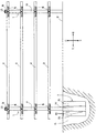
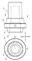
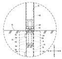
図1において、1は支柱であり、その下部は地中Gに埋設され適宜間隔で複数本地表に左右方向に立設されている。この支柱1の側壁11の正面側と背面側の適宜位置に、柵ビーム2を前記支柱1に取付けるための取付金具Kを係止するための金具取付孔が相対して同一水準で穿設されている。
In FIG. 1, 1 is a support column, the lower portion thereof is buried in the underground G, and a plurality of columns are erected on the ground surface in the left-right direction at appropriate intervals. Bracket mounting holes for locking the mounting bracket K for mounting the
前記支柱1の頂部にはキャップ13が取付られ、見栄えを良くすると共に、雨水などが支柱1の内面に流入するのを防いでいる。支柱1は断面円形状等の適宜断面形状の金属管で作製され、その表面は塗装やメッキ等の処理が施されている。また、キャップ13下部には全周にわたって帯状の反射体Rが巻回されて取付けられており、視線誘導効果を呈している。
A
2は柵ビームであり、複数の支柱1の相対向する側壁11間に取付金具Kを介して複数段(本実施形態では4段)架設されている。柵ビーム2も、一般的に従来から用いられている断面円形状等の適宜断面形状の金属管で作製されている。
前記支柱1は、一般にはアルミニウム、ステンレス、鉄鋼等のパイプ、形材からなる長尺体を適宜長さに切断したものや、それらにめっき、塗装を施したもの等を好適に用いることができる。
As the
前記柵ビーム2は、前記支柱1と同様に、一般にはアルミニウム、ステンレス、鉄鋼等のパイプ、形材からなる長尺体を適宜長さに切断したものや、それらにめっき、塗装を施したもの等を好適に用いることができる。
Similar to the
なお本実施形態において、前記柵ビーム2は上下に4段で前記支柱1に取付けられているが、特に4段に限定されるものではなく、適宜の段数で取付けられれば良い。また、本実施形態においては道路付帯設備として防護柵をあげて説明しているが、これに限定されるものではなく、支柱を備えている他の道路付帯設備、例えば、車止めや照明柱などにも本発明は適用されるものである。
In the present embodiment, the
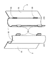
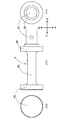
3は支柱用基礎部材であって、縦板部31から側方に向けて前記支柱1の外形に対応した支柱保持部32が延設され、該支柱保持部32の先端には、前記支柱保持部32の基端に設けられた挿通孔33に挿入され係合される係合部34が設けられている。そして、図1、4、5、に示す様に、前記支柱用基礎部材3が2個セットで用いられる場合、図2、3に示す形態の支柱用基礎部材3を2個用いられ、一方の支柱用基礎部材3の挿通孔33に他方の支柱用基礎部材3の係合部34が挿入され係合されて、土中に埋設されて用いられる。図2、3に示す実施形態においては、前記支柱用基礎部材3の前記支柱保持部32は平面視(底面視)で半円弧状に形成されており、2個の前記支柱用基礎部材3の一方の挿通孔33に他方の支柱用基礎部材3の係合部34を挿入し係合すると、平面視(底面視)で円形になる。
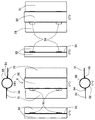
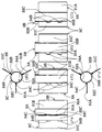
また、図8、9に示す様に、一方の前記支柱用基礎部材3Aの挿通孔33Aに他方の前記支柱用基礎部材3Bの係合部34Bが挿入され係合され、前記他方の支柱用基礎部材3Bの挿通孔33Bにさらに別の前記支柱用基礎部材3Cの係合部34Cが挿入され係合され、前記一方の支柱用基礎部材3Aの係合部34Aが前記別の支柱用基礎部材3Cの挿通孔33Cに挿入され係合されて用いられる場合もある。すなわち、図6、7に示す実施形態の前記支柱用基礎部材3が3個セットで用いられる場合である。この図6、7に示す実施形態においては、前記支柱用基礎部材3の前記支柱保持部32は平面視(底面視)で三分の一円弧状に形成されており、3個の前記支柱用基礎部材3のうち、一方の前記支柱用基礎部材3Aの挿通孔33Aに他方の前記支柱用基礎部材3Bの係合部34Bが挿入され係合され、前記他方の支柱用基礎部材3Bの挿通孔33Bにさらに別の前記支柱用基礎部材3Cの係合部34Cが挿入され係合され、前記一方の支柱用基礎部材3Aの係合部34Aが前記別の支柱用基礎部材3Cの挿通孔33Cに挿入され係合されると、平面視(底面視)で円形になる。
Further, as shown in FIGS. 8 and 9, the engaging
次に、図21〜図24に示す実施形態について説明する。これらの図に示す実施形態は、図6〜9に示す実施形態と類似しており、3個の支柱用基礎部材3を組んで用いるものである。すなわち、一方の前記支柱用基礎部材3Aの挿通孔33Aに他方の前記支柱用基礎部材3Bの係合部34Bが挿入され係合され、前記他方の支柱用基礎部材3Bの挿通孔33Bにさらに別の前記支柱用基礎部材3Cの係合部34Cが挿入され係合され、前記一方の支柱用基礎部材3Aの係合部34Aが前記別の支柱用基礎部材3Cの挿通孔33Cに挿入され係合されて用いられる。ただ、図6〜9に示す実施形態と相違するのは、図21、22に示す様に、前記係合部34の基端部側の下部が切欠かれて、切欠部35が形成されている点である。上述の様に、3個の前記支柱用基礎部材3A、3B、3Cのそれぞれの挿通孔33A、33B、33Cに、それぞれの係合部34A、34B、34Cを挿入した後、それぞれの支柱用基礎部材3A、3B、3Cを下方(或いは上方)に動かして、それぞれの前記切欠部35A、35B、35Cにそれぞれの前記挿通孔33A、33B、33Cの下部の周辺部を係合させる。こうすることにより、3個の前記支柱用基礎部材3を組んだ状態で地中に打ち込む際、組んだ3個の前記支柱用基礎部材3A、3B、3Cに様々な方向から力が作用しても、それぞれの前記支柱用基礎部材3A、3B、3C同士がしっかりと係合されているので、それぞれの前記支柱用基礎部材3A、3B、3C同士がズレるなどして、前記支柱用基礎部材3、3A、3B、3Cが変形することなどを抑止することができる。
Next, the embodiments shown in FIGS. 21 to 24 will be described. The embodiments shown in these figures are similar to the embodiments shown in FIGS. 6 to 9, and are used by assembling three
なお、図21〜図24に示す実施形態においては、前記係合部35、35A、35B、35Cを前記係合部34、34A、34B、34Cの基端部側の下部に形成しているが、特にこれに限定されるものではなく、前記係合部35、35A、35B、35Cを前記係合部34、34A、34B、34Cの基端部側の上部に形成してもよいし、前記係合部34、34A、34B、34Cの基端部側の上部と下部の両方に形成してもよい。要は、前記切欠部34、35A、35B、35Cに前記挿通孔33、33A、33B、33Cの周辺部を係合できる様に形成されていればよい。
In the embodiment shown in FIGS. 21 to 24, the engaging
本明細書に記載の実施形態においては、前記支柱1は円筒管で形成されており、前記支柱用基礎部材3のもその外形に対応した円筒形状になる様に形成されているが、特にこの形状に限定されるものではなく、前記支柱1が挿入可能な形状に前記支柱保持部32を形成すればよい。例えば、本明細書に記載の実施形態に示す様に、前記支柱1が円筒管で形成されている場合であっても、前記支柱保持部32を前記支柱1の外径より大きな内形の四角形状に形成してもよい。また前記支柱1が四角柱管で形成されていれば、前記支柱保持部32もその外形に対応して前記支柱1の外形よりやや大きい四角形状に形成してもよいし、前記支柱1の外形よりやや大きい内径を備えた円筒形になる様に前記支柱保持部32を形成してもよい。
In the embodiment described in the present specification, the
前記支柱用基礎部材3が2個セットで用いられる場合も、前記支柱用基礎部材3が3個セットで用いられる場合も、前記係合部34は縦板状に形成され、前記挿通孔33は前記係合部34が挿入可能な形状、本実施形態においては縦長形状に形成されている。これによって、前記支柱用基礎部材3を金属製の平板からプレス加工で作成する際、前記係合部34と前記挿通孔33を打ち抜く金型と、前記支柱保持部32を前記支柱1の外形に対応した形状に成型する金型とで、前記支柱用基礎部材3を作成することができるので、金型コストを抑えて前記支柱用基礎部材3を作成することができ、加えて、平板から切り落として廃棄する部分を少なくすることができるので、前記支柱用基礎部材3を効率(歩留り)よく作成することができる。
Whether the
次に、打ち込み機具(図示せず)を用いて前記支柱用基礎部材3や鋼管杭基礎Qを地中Gに打ち込む際に用いる打ち込み治具4と、該打ち込み治具4を用いて前記支柱用基礎部材3や鋼管杭基礎Qを地中Gに打ち込む方法について、図10〜20を用いて説明する。
Next, a driving jig 4 used when driving the
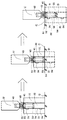
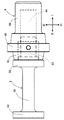
まず図10、11に示す実施形態の打ち込み治具4は、前記支柱用基礎部材3や鋼管杭基礎Qの内形に対応した基礎部挿入部41と、前記打ち込み機具の打ち込み部Uまたは該打ち込み部Uに取付けられる打ち込み補助具Hの内形に対応した打ち込み部挿入部42とを備え、前記基礎部挿入部41と前記打ち込み部挿入部42とを連結すると共に、前記支柱用基礎部材3や鋼管杭基礎Qの上端と前記打ち込み機具の打ち込み部Uまたは前記打ち込み補助具Hの下端とに当接される連結部43を備えている。
First, the driving jig 4 of the embodiment shown in FIGS. 10 and 11 includes a foundation
そして、前記連結部43の外形は、前記支柱用基礎部材3または鋼管杭基礎Q、及び前記打ち込み機具の打ち込み部Uまたは前記打ち込み補助具Hの内形より大きく形成され、前記連結部43の外形は、前記支柱用基礎部材3または鋼管杭基礎Q、及び前記打ち込み機具の打ち込み部Uまたは前記打ち込み補助具Hの外形より大きく形成されている。
The outer shape of the connecting
また、前記基礎部挿入部41の底部411から前記打ち込み部挿入部42にかけて段付きの円筒形状の中空部44が形成され、後述する土砂押圧具5が前記中空部44に挿着されて、前記打ち込み治具4に前記土砂押圧具5がボルト(図示せず)などを用いて固定されている。
Further, a stepped cylindrical
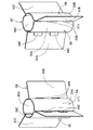
前記土砂押圧具5は、前記基礎部挿入部41の中空部44に挿入される土砂押圧具挿入部51から、前記打ち込み治具4の底部411に当接する扁平な円柱形状の当接部52が設けられ、該当接部52から円柱状の接続部53が延設されている。そして、前記接続部53の先端には、前記支柱用基礎部材3または鋼管杭基礎Qの内側に挿入され、前記支柱用基礎部材3または鋼管杭基礎Qが地中Gに打ち込まれていくにしたがい、前記支柱用基礎部材3または鋼管杭基礎Qの内側の土砂を下方に押圧していく押圧部54が延設されている。そして、前記接続部53の外径は前記押圧部54の外径より小さく形成されている。また、前記接続部53及び押圧部54の外径は前記土砂押圧具5が前記支柱用基礎部材3または鋼管杭基礎Qの内側に挿入できる様に、前記支柱用基礎部材3または鋼管杭基礎Qの内径よりやや小さく形成されている。
The earth and sand pressing tool 5 has a flat
本実施形態においては、前記支柱用基礎部材3の支柱保持部32や鋼管杭基礎Qが円筒形状になっているため、前記押圧部54も扁平な円柱形状となっているが、特に円筒形状に限定されるものではなく、前記支柱用基礎部材3の支柱保持部32や鋼管杭基礎Qの形状に対応した形状であればよい。
In the present embodiment, since the
また、本明細書に記載の実施形態においては、前記支柱用基礎部材3や鋼管杭基礎Qが円筒管状に形成されているので、前記連結部43の外形、前記支柱用基礎部材3や鋼管杭基礎Qと前記打ち込み機具の打ち込み部Uまたは前記打ち込み補助具Hの内形及び外形は、全て円形となされている。また、図14、15、18、19に示す通り、本実施形態に示す前記打ち込み補助具Hは、前記支柱用基礎部材3の支柱保持部32や前記鋼管杭基礎Qとほぼ同径の円柱状の鋼管で形成されている。
Further, in the embodiment described in the present specification, since the
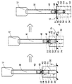
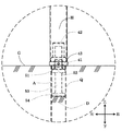
次に、前記打ち込み治具4を用いて前記支柱用基礎部材3や鋼管杭基礎Qを地中Gに打ち込む方法について、図12〜19を用いて説明する。図12、13に示す実施形態は、前記打ち込み部Uに前記打ち込み治具4の打ち込み部挿入部42を直接挿着し、前記支柱用基礎部材3を地中Gに打ち込む場合を示している。前記支柱用基礎部材3を地表に載置し、その上方から前記打ち込み部Uに取付けられた前記打ち込み治具4の基礎部挿入部41を挿入し、前記打ち込み機具により下方に押圧し、前記支柱用基礎部材3を地中Gに徐々に打ち込んで、前記支柱用基礎部材3を地中Gに完全に埋設して、施工が完了する。この時、前記支柱用基礎部材3または鋼管杭基礎Qの内部の土砂Dは前記土砂押圧具5により下方に押圧されて、前記支柱1を配置できる空間Aが形成されている。
Next, a method of driving the
図14、15に示す実施形態は、前記打ち込み補助具Hの下端部に前記打ち込み治具4の打ち込み部挿入部42を挿着し、前記打ち込み補助具Hの上端部に前記打ち込み部Uが挿着されて、前記支柱用基礎部材3を地中Gに打ち込む場合を示している。前記支柱用基礎部材3を地表に載置し、その上方から、前記打ち込み補助具Hの下端部に前記基礎部挿入部41が挿入された前記打ち込み治具4の前記基礎部挿入部41を挿入し、前記支柱用基礎部材3が前記打ち込み機具により下方に押圧され、前記支柱用基礎部材3が地中Gに徐々に打ち込まれて、前記支柱用基礎部材3を地中Gに完全に埋設して、施工が完了する。この時、前記支柱用基礎部材3または鋼管杭基礎Qの内部の土砂Dは前記土砂押圧具5により下方に押圧されて、前記支柱1を配置できる空間Aが形成されている。
In the embodiment shown in FIGS. 14 and 15, the driving
図16、17に示す実施形態は、前記打ち込み部Uに前記打ち込み治具4の打ち込み部挿入部42を直接挿着し、前記鋼管杭基礎Qを地中Gに打ち込む場合を示している。前記鋼管杭基礎Qを地表に立設させて、その上方から前記打ち込み部Uに取付けられた前記打ち込み治具4の基礎部挿入部41を挿入し、前記打ち込み機具により下方に押圧し、前記鋼管杭基礎Qを地中Gに徐々に打ち込んで、前記鋼管杭基礎Qを地中Gに完全に埋設して、施工が完了する。この時、前記支柱用基礎部材3または鋼管杭基礎Qの内部の土砂Dは前記土砂押圧具5により下方に押圧されて、前記支柱1を配置できる空間Aが形成されている。
The embodiments shown in FIGS. 16 and 17 show a case where the driving
図18、19に示す実施形態は、前記打ち込み補助具Hの下端部に前記打ち込み治具4の打ち込み部挿入部42を挿着し、前記打ち込み補助具Hの上端部に前記打ち込み部Uが挿着されて、前記鋼管杭基礎Qを地中Gに打ち込む場合を示している。前記鋼管杭基礎Qを地表に立設させて、その上方から、前記打ち込み補助具Hの下端部に前記基礎部挿入部41が挿入された前記打ち込み治具4の前記基礎部挿入部41を挿入し、前記鋼管杭基礎Qが前記打ち込み機具により下方に押圧され、前記鋼管杭基礎Qが地中Gに徐々に打ち込まれて、前記鋼管杭基礎Qを地中Gに完全に埋設して、施工が完了する。この時、前記支柱用基礎部材3または鋼管杭基礎Qの内部の土砂Dは前記土砂押圧具5により下方に押圧されて、前記支柱1を配置できる空間Aが形成されている。
In the embodiments shown in FIGS. 18 and 19, the driving
なお、本明細書に記載の実施形態においては、前記土砂押圧具5を前記打ち込み治具4に取付けて、前記支柱用基礎部材3または鋼管杭基礎Qの地中Gへの打ち込み作業を行っているが、これに限定されるものではなく、前記支柱用基礎部材3または鋼管杭基礎Qの内部の土砂Dを下方に押圧するだけの力を備えていない打ち込み機具を用いる場合には、前記打ち込み治具4のみを用いて前記支柱用基礎部材3または鋼管杭基礎Qを地中Gへの打ち込み作業を行ってもよい。その場合には、前記支柱用基礎部材3または鋼管杭基礎Qを地中Gへの打ち込み作業を終えた後、作業者により、前記支柱1を配置できる空間Aを形成する必要がある
In the embodiment described in the present specification, the earth and sand pressing tool 5 is attached to the driving jig 4, and the
1 支柱
11 側壁
12 金具取付孔
13 キャップ
2 柵ビーム
21 端部
22 柵ビーム取付孔
3、3A、3B、3C 支柱用基礎部材
31、31A、31B、31C 縦板部
32、32A、32B、32C 支柱保持部
33、33A、33B、33C 挿通孔
34、34A、34B、34C 係合部
35、35A、35B、35C 切欠部
4 打ち込み治具
41 基礎部挿入部
411 底部
42 打ち込み部挿入部
43 連結部
44 中空部
5 土砂押圧具
51 押圧部挿入部
52 当接部
53 接続部
54 押圧部
R 反射体
K 取付金具
Q 鋼管杭基礎
G 地中
U 打ち込み部
H 打ち込み補助具
D 土砂
A 空間
1
Claims (8)
前記係合部は縦板状に形成され、前記挿通孔は前記係合部が挿入可能な形状に形成されており、
前記挿通孔に挿入されて該挿通孔に係合された前記係合部が前記縦板部に沿って配置されるように形成されていることを特徴とする支柱用基礎部材。 A strut holding portion extends laterally from the vertical plate portion, and at the tip of the strut holding portion, an engaging portion that is inserted into and engaged with an insertion hole provided at the base end of the strut holding portion is provided. It is provided ,
The engaging portion is formed in a vertical plate shape, and the insertion hole is formed in a shape into which the engaging portion can be inserted.
A support base member characterized in that the engaging portion inserted into the insertion hole and engaged with the insertion hole is formed so as to be arranged along the vertical plate portion .
前記係合部は縦板状に形成され、前記挿通孔は前記係合部が挿入可能な形状に形成されており、
前記支柱保持部が構成する筒の内側方向から前記挿通孔に挿入されて係合された前記係合部が前記縦板部に沿って配置されるように形成されていることを特徴とする支柱用基礎部材。 A strut holding portion extends laterally from the vertical plate portion, and at the tip of the strut holding portion, an engaging portion that is inserted into and engaged with an insertion hole provided at the base end of the strut holding portion is provided. It is provided ,
The engaging portion is formed in a vertical plate shape, and the insertion hole is formed in a shape into which the engaging portion can be inserted.
The strut is formed so that the engaging portion inserted into and engaged with the insertion hole from the inside of the cylinder formed by the strut holding portion is arranged along the vertical plate portion. Basic member for.
Applications Claiming Priority (2)
| Application Number | Priority Date | Filing Date | Title |
|---|---|---|---|
| JP2016131451 | 2016-07-01 | ||
| JP2016131451 | 2016-07-01 |
Publications (2)
| Publication Number | Publication Date |
|---|---|
| JP2018009436A JP2018009436A (en) | 2018-01-18 |
| JP6830793B2 true JP6830793B2 (en) | 2021-02-17 |
Family
ID=60995264
Family Applications (1)
| Application Number | Title | Priority Date | Filing Date |
|---|---|---|---|
| JP2016215057A Active JP6830793B2 (en) | 2016-07-01 | 2016-11-02 | A driving jig used when driving a support foundation member and the support support foundation member into the ground. |
Country Status (1)
| Country | Link |
|---|---|
| JP (1) | JP6830793B2 (en) |
Families Citing this family (3)
| Publication number | Priority date | Publication date | Assignee | Title |
|---|---|---|---|---|
| JP7084712B2 (en) * | 2017-11-21 | 2022-06-15 | 日鉄神鋼建材株式会社 | Steel foundation members for road guard fences, road guard fences, and their construction methods |
| JP7132681B2 (en) * | 2018-08-14 | 2022-09-07 | 日鉄神鋼建材株式会社 | Foundation members of road protection fences, road protection fences, and construction methods thereof |
| KR102160619B1 (en) * | 2020-04-24 | 2020-09-28 | 주식회사 임성 | A Foundation Pile |
-
2016
- 2016-11-02 JP JP2016215057A patent/JP6830793B2/en active Active
Also Published As
| Publication number | Publication date |
|---|---|
| JP2018009436A (en) | 2018-01-18 |
Similar Documents
| Publication | Publication Date | Title |
|---|---|---|
| KR101242476B1 (en) | Base construct method of building and base construct member of building | |
| KR100960891B1 (en) | Bridge for bicycle and pedestrian and this construction technique | |
| JP6830793B2 (en) | A driving jig used when driving a support foundation member and the support support foundation member into the ground. | |
| JP2010106494A (en) | Foundation pile for erecting post, and post erecting method using the same | |
| JP5694598B2 (en) | Guard fence post for replacement bridge in existing ground-covered concrete | |
| KR20150101742A (en) | Deckroad using stand alone pile and installing method thereof | |
| KR101742292B1 (en) | Support device for post | |
| JP4420697B2 (en) | Standing structure of steel pipe columns | |
| JP3178731U (en) | Steel tower foundation structure | |
| JP5308260B2 (en) | Prop installation structure | |
| JP2011024533A (en) | Agricultural greenhouse, doorsill material of the same, method for constructing the agricultural greenhouse, and method for mounting the doorsill material of the agricultural greenhouse | |
| JP4444074B2 (en) | L-shaped side gutter with earth retaining wall | |
| JP5554662B2 (en) | How to repair gutter | |
| JP5505979B2 (en) | How to repair gutter | |
| KR101663174B1 (en) | A based pile with based pile tip and construction method therefor | |
| KR101882257B1 (en) | Apparatus for constructing a short pipe and Method for constructing a column using the same | |
| JP5415494B2 (en) | Bollard foundation method and bollard foundation structure | |
| KR100725844B1 (en) | Higgs stock holder | |
| KR101695720B1 (en) | A based pile tip connected type based pile and construction method therefor | |
| KR101786067B1 (en) | Small caliber pile composite concrete column and Small caliber pile composite concrete column construction method | |
| JP6467136B2 (en) | Guard fence and guard fence | |
| KR102184081B1 (en) | Construction method for perforating goround bore using inverse casing | |
| JP2007291736A (en) | Block for support foundation | |
| JP4214088B2 (en) | Forming mold for column installation | |
| KR100680286B1 (en) | Foundation pile structure |
Legal Events
| Date | Code | Title | Description |
|---|---|---|---|
| A621 | Written request for application examination |
Free format text: JAPANESE INTERMEDIATE CODE: A621 Effective date: 20190924 |
|
| A131 | Notification of reasons for refusal |
Free format text: JAPANESE INTERMEDIATE CODE: A131 Effective date: 20200818 |
|
| A977 | Report on retrieval |
Free format text: JAPANESE INTERMEDIATE CODE: A971007 Effective date: 20200814 |
|
| A521 | Written amendment |
Free format text: JAPANESE INTERMEDIATE CODE: A523 Effective date: 20201009 |
|
| TRDD | Decision of grant or rejection written | ||
| A01 | Written decision to grant a patent or to grant a registration (utility model) |
Free format text: JAPANESE INTERMEDIATE CODE: A01 Effective date: 20210126 |
|
| A61 | First payment of annual fees (during grant procedure) |
Free format text: JAPANESE INTERMEDIATE CODE: A61 Effective date: 20210127 |
|
| R150 | Certificate of patent or registration of utility model |
Ref document number: 6830793 Country of ref document: JP Free format text: JAPANESE INTERMEDIATE CODE: R150 |