JP6830795B2 - Silencer - Google Patents
Silencer Download PDFInfo
- Publication number
- JP6830795B2 JP6830795B2 JP2016219101A JP2016219101A JP6830795B2 JP 6830795 B2 JP6830795 B2 JP 6830795B2 JP 2016219101 A JP2016219101 A JP 2016219101A JP 2016219101 A JP2016219101 A JP 2016219101A JP 6830795 B2 JP6830795 B2 JP 6830795B2
- Authority
- JP
- Japan
- Prior art keywords
- valve body
- valve
- valve seat
- silencer
- communication hole
- Prior art date
- Legal status (The legal status is an assumption and is not a legal conclusion. Google has not performed a legal analysis and makes no representation as to the accuracy of the status listed.)
- Active
Links
Images
Classifications
-
- F—MECHANICAL ENGINEERING; LIGHTING; HEATING; WEAPONS; BLASTING
- F01—MACHINES OR ENGINES IN GENERAL; ENGINE PLANTS IN GENERAL; STEAM ENGINES
- F01N—GAS-FLOW SILENCERS OR EXHAUST APPARATUS FOR MACHINES OR ENGINES IN GENERAL; GAS-FLOW SILENCERS OR EXHAUST APPARATUS FOR INTERNAL-COMBUSTION ENGINES
- F01N1/00—Silencing apparatus characterised by method of silencing
- F01N1/02—Silencing apparatus characterised by method of silencing by using resonance
-
- F—MECHANICAL ENGINEERING; LIGHTING; HEATING; WEAPONS; BLASTING
- F04—POSITIVE - DISPLACEMENT MACHINES FOR LIQUIDS; PUMPS FOR LIQUIDS OR ELASTIC FLUIDS
- F04B—POSITIVE-DISPLACEMENT MACHINES FOR LIQUIDS; PUMPS
- F04B39/00—Component parts, details, or accessories, of pumps or pumping systems specially adapted for elastic fluids, not otherwise provided for in, or of interest apart from, groups F04B25/00 - F04B37/00
- F04B39/10—Adaptations or arrangements of distribution members
-
- F—MECHANICAL ENGINEERING; LIGHTING; HEATING; WEAPONS; BLASTING
- F16—ENGINEERING ELEMENTS AND UNITS; GENERAL MEASURES FOR PRODUCING AND MAINTAINING EFFECTIVE FUNCTIONING OF MACHINES OR INSTALLATIONS; THERMAL INSULATION IN GENERAL
- F16K—VALVES; TAPS; COCKS; ACTUATING-FLOATS; DEVICES FOR VENTING OR AERATING
- F16K1/00—Lift valves or globe valves, i.e. cut-off apparatus with closure members having at least a component of their opening and closing motion perpendicular to the closing faces
- F16K1/32—Details
- F16K1/34—Cutting-off parts, e.g. valve members, seats
-
- F—MECHANICAL ENGINEERING; LIGHTING; HEATING; WEAPONS; BLASTING
- F16—ENGINEERING ELEMENTS AND UNITS; GENERAL MEASURES FOR PRODUCING AND MAINTAINING EFFECTIVE FUNCTIONING OF MACHINES OR INSTALLATIONS; THERMAL INSULATION IN GENERAL
- F16K—VALVES; TAPS; COCKS; ACTUATING-FLOATS; DEVICES FOR VENTING OR AERATING
- F16K15/00—Check valves
- F16K15/02—Check valves with guided rigid valve members
Landscapes
- Engineering & Computer Science (AREA)
- General Engineering & Computer Science (AREA)
- Mechanical Engineering (AREA)
- Chemical & Material Sciences (AREA)
- Combustion & Propulsion (AREA)
- Compressor (AREA)
- Check Valves (AREA)
- Lift Valve (AREA)
- Exhaust Silencers (AREA)
- Details Of Valves (AREA)
- Applications Or Details Of Rotary Compressors (AREA)
Description
本発明は、消音器に関する。 The present invention relates to a silencer.
ポンプまたは圧縮機のように流体の移動を伴う装置では、流体の出口で騒音に繋がる大きな音波が生じていることが知られている。この音波を減衰できることは騒音防止の観点から有用である。 It is known that in devices that involve the movement of fluid, such as pumps or compressors, loud sound waves that lead to noise are generated at the outlet of the fluid. Being able to attenuate this sound wave is useful from the viewpoint of noise prevention.
このような音波の減衰機能を備える消音器が、例えば特許文献1に開示されている。特許文献1の消音器は、真空ポンプの排気口から排出される気体の持つ騒音を低減させる消音機能を有している。さらに、この消音器は、逆止弁を備えており、上記消音機能とともに気体の逆流を抑制する逆流抑制機能も有している。
A silencer having such a sound wave attenuation function is disclosed in, for example,
特許文献1の消音器が備える逆止弁は、逆流抑制機能を実現するために設けられており、消音要素としては機能していない。従って、この消音器は、逆止弁構造について未だ改善の余地がある。
The check valve included in the silencer of
本発明は、逆流抑制機能と消音機能を併せ持つ逆止弁構造を有する消音器を提供することを課題とする。 An object of the present invention is to provide a muffler having a check valve structure having both a check flow suppressing function and a muffling function.
本発明の消音器は、吐出口を有して内部に膨張室を画定する膨張部と、内部に誘導室を画定する有限長の誘導管を有する音響エレメントと、前記膨張室と前記誘導室とを連通する連通孔が設けられた接続部と、前記誘導室から前記連通孔を通って前記膨張室へと流れる流体が逆流することを防止するための逆止弁とを備える消音器であって、前記逆止弁は、前記接続部に設けられた弁座と、前記弁座と当接して前記連通孔を塞ぐ弁体と、前記弁体を前記弁座に向かって付勢する付勢部材とを備え、前記弁体は、周縁部に設けられ、前記弁座と当接する部分であって、前記弁座に向かって先細る形状を有するテーパ部と、前記テーパ部の内側に設けられた平板部と、前記弁座と対向する面と反対面に設けられた凹部とを備える、消音器を提供する。 In the silencer of the present invention, an expansion portion having a discharge port and defining an expansion chamber inside, an acoustic element having a finite length guide tube that defines a guide chamber inside, and the expansion chamber and the guide chamber A muffler including a connection portion provided with a communication hole for communicating with the above and a check valve for preventing the fluid flowing from the guide chamber to the expansion chamber through the communication hole from flowing back. The check valve includes a valve seat provided at the connection portion, a valve body that contacts the valve seat and closes the communication hole, and an urging member that urges the valve body toward the valve seat. The valve body is provided on the peripheral edge portion and is a portion that comes into contact with the valve seat, and is provided with a tapered portion having a shape that tapers toward the valve seat and inside the tapered portion. Provided is a silencer provided with a flat plate portion and a recess provided on a surface facing the valve seat and a surface opposite to the valve seat.
この構成によれば、逆流抑制機能と消音機能を併せ持つ逆止弁構造を有する消音器を提供でき、従来と比較して省スペースで高い消音効果を得ることができる。具体的には、弁体が弁座と当接するとき、テーパ部で連通孔を塞ぐため、連通孔を正確に塞ぐことができる。仮に、弁体がテーパ部を有しておらず平板部で連通孔を塞ぐ場合、平板部の組立公差または製造公差等によっては、弁座に正確に当接できず、即ち連通孔を正確に塞ぐことができず、逆止弁としての機能を果たさないおそれがある。上記構成では、テーパ部によってこの問題を抑制し、流体の逆流を安定して抑制できる。さらに、弁体の一部をテーパ状にすることで弁体の剛性を向上できるため、必要な曲げ剛性を得るための板厚を薄くすることができる。その結果、単なる平板状の場合と比べて弁体を軽量化でき、コストダウンとなる。また、弁体がテーパ部で弁座と当接することで、平板部で当接する場合と比べて流体の流路が徐々に広がるため、圧力損失の増大を抑制できる。また、逆止弁が付勢部材を備えることで、付勢部材の上流側(誘導室側)の圧力が下流側(膨張室側)よりも一定以上高い場合にのみ逆止弁が開く。即ち、付勢部材によって簡易に逆流抑制機能を実現できる。また、弁体が弁座と対向する面と反対面に凹部を有することで、連通孔を通過した流体に重畳した音波が凹部に回り込む回折現象が生じる。そのため、音波の回折減衰による減音効果を得ることができる。また、弁体を保持する面と吐出口を有する面とが異なっているため、吐出口以外から弁体にアクセスできる。そのため、例えば吐出口以降に配管を設けた場合でも配管を取り外すことなく、逆止弁のメンテナンスが可能である。このように逆止弁を効率的にメンテナンスするためには、吐出口以外から逆止弁に対して外部からアクセス可能なように膨張部に吐出口以外の開口部を設けることが好ましい。 According to this configuration, it is possible to provide a muffler having a check valve structure having both a backflow suppression function and a muffling function, and it is possible to obtain a high muffling effect in a space saving as compared with the conventional case. Specifically, when the valve body comes into contact with the valve seat, the communication hole is closed by the tapered portion, so that the communication hole can be closed accurately. If the valve body does not have a tapered portion and the communication hole is closed by the flat plate portion, the communication hole cannot be accurately contacted with the valve seat due to the assembly tolerance or manufacturing tolerance of the flat plate portion, that is, the communication hole is accurately formed. It cannot be closed and may not function as a check valve. In the above configuration, this problem can be suppressed by the tapered portion, and the backflow of the fluid can be stably suppressed. Further, since the rigidity of the valve body can be improved by making a part of the valve body tapered, the plate thickness for obtaining the required flexural rigidity can be reduced. As a result, the weight of the valve body can be reduced as compared with the case of a simple flat plate, and the cost can be reduced. Further, when the valve body comes into contact with the valve seat at the tapered portion, the flow path of the fluid gradually expands as compared with the case where the valve body abuts at the flat plate portion, so that an increase in pressure loss can be suppressed. Further, since the check valve is provided with the urging member, the check valve opens only when the pressure on the upstream side (induction chamber side) of the urging member is higher than the downstream side (expansion chamber side) by a certain amount or more. That is, the backflow suppression function can be easily realized by the urging member. Further, since the valve body has a recess on the surface opposite to the surface facing the valve seat, a diffraction phenomenon occurs in which the sound wave superimposed on the fluid passing through the communication hole wraps around the recess. Therefore, the sound reduction effect due to the diffraction attenuation of the sound wave can be obtained. Further, since the surface that holds the valve body and the surface that has the discharge port are different, the valve body can be accessed from other than the discharge port. Therefore, for example, even if a pipe is provided after the discharge port, the check valve can be maintained without removing the pipe. In order to efficiently maintain the check valve in this way, it is preferable to provide an opening other than the discharge port in the expansion portion so that the check valve can be accessed from the outside from other than the discharge port.
前記消音器は、前記逆止弁の最大開度を規制する規制部材をさらに備えてもよい。 The silencer may further include a regulating member that regulates the maximum opening degree of the check valve.
この構成によれば、規制部材により逆止弁の最大開度を規制できるため、消音効果が著しく弱まることを防止できる。具体的には、逆止弁の開度が大きくなると、弁体と干渉せずに吐出口まで通過する音波が増えるため、弁体による音波の減衰量が小さくなる。即ち、弁体が弁座に近い位置にあるほど、大きな消音効果を期待できる。上記構成では、逆止弁の最大開度が規制されるため、最大開度においても所定の減衰量を確保できる。所定の減衰量は規制部材によって規制される逆止弁の最大開度に応じて変化するが、これは許容される騒音の音量に応じて決定されればよい。 According to this configuration, since the maximum opening degree of the check valve can be regulated by the regulating member, it is possible to prevent the muffling effect from being significantly weakened. Specifically, as the opening degree of the check valve increases, the amount of sound waves that pass to the discharge port without interfering with the valve body increases, so that the amount of sound wave attenuation by the valve body decreases. That is, the closer the valve body is to the valve seat, the greater the sound deadening effect can be expected. In the above configuration, since the maximum opening degree of the check valve is regulated, a predetermined damping amount can be secured even at the maximum opening degree. The predetermined damping amount changes according to the maximum opening degree of the check valve regulated by the regulating member, which may be determined according to the allowable noise volume.
前記規制部材は、前記弁体を挟んで前記弁座と反対側に設けられており、前記弁体は、前記吐出口に向かって前記規制部材よりも突出していてもよい。 The regulating member is provided on the side opposite to the valve seat with the valve body interposed therebetween, and the valve body may protrude from the regulating member toward the discharge port.
この構成によれば、弁体が規制部材よりも吐出口に向かって突出しているため、弁体を挟んで規制部材側から弁座側へと向かう音波の伝搬を阻害する。従って、この阻害により音波が減衰されるため、消音器としての減音効果を高めることができる。 According to this configuration, since the valve body protrudes from the regulating member toward the discharge port, the propagation of sound waves from the regulating member side to the valve seat side across the valve body is hindered. Therefore, since the sound wave is attenuated by this inhibition, the sound reduction effect as a silencer can be enhanced.
前記連通孔と前記吐出口とを直線的に結ぶ空間内に前記弁体の少なくとも一部が配置されていてもよい。 At least a part of the valve body may be arranged in a space that linearly connects the communication hole and the discharge port.
この構成によれば、膨張室入口(連通孔)から膨張室出口(吐出口)に向かう音波に弁体が干渉するため、より確実に回折減衰による減音効果を得ることができる。 According to this configuration, since the valve body interferes with the sound wave from the expansion chamber inlet (communication hole) to the expansion chamber outlet (discharge port), the sound reduction effect due to diffraction attenuation can be obtained more reliably.
前記連通孔の連通方向から見て、前記弁体の面積は、前記膨張室の断面積の70%未満であってもよい。 The area of the valve body may be less than 70% of the cross-sectional area of the expansion chamber when viewed from the communication direction of the communication holes.
この構成によれば、弁体を音響的に剛の境界としないことで音響エレメント内における弁体へ向かう音波と弁体で反射した音波の共鳴を抑制できる。一般に、弁体は大きいほど音波の進行を阻害するため、弁体は大きいほど減音効果は大きい。しかし、弁体を一定以上大きくすると、音響エレメント内で弁体へ向かう音波と弁体で反射した音波の共鳴が発生する。本願発明者は、膨張室の断面積に対して弁体の面積が70%以上であるときに、上記共鳴が発生することを見出した。従って、弁体の面積を膨張室の断面積の70%未満とすることで、弁体が剛壁として機能することを防止し、弁体での音波の反射量を低減させ、この共鳴を抑制できる。これにより、特定周波数における減音効果の落ち込みを抑制できる。 According to this configuration, the resonance between the sound wave toward the valve body and the sound wave reflected by the valve body in the acoustic element can be suppressed by not making the valve body an acoustically rigid boundary. In general, the larger the valve body, the more the sound wave progression is hindered. Therefore, the larger the valve body, the greater the sound reduction effect. However, when the valve body is made larger than a certain level, resonance between the sound wave toward the valve body and the sound wave reflected by the valve body is generated in the acoustic element. The inventor of the present application has found that the above resonance occurs when the area of the valve body is 70% or more with respect to the cross-sectional area of the expansion chamber. Therefore, by making the area of the valve body less than 70% of the cross-sectional area of the expansion chamber, it is possible to prevent the valve body from functioning as a rigid wall, reduce the amount of sound waves reflected by the valve body, and suppress this resonance. it can. As a result, it is possible to suppress a drop in the sound reduction effect at a specific frequency.
前記音響エレメントは、前記誘導室内に共鳴防止構造を備えてもよい。 The acoustic element may be provided with a resonance prevention structure in the induction chamber.
この構成によれば、共鳴防止構造により、音響エレメント内における共鳴を抑制し、特定周波数における消音効果の落ち込みを抑制できる。特に、音響エレメントが共鳴防止構造を備えると、弁体の形状によらず、音響エレメント内における共鳴を抑制できる。従って、音響エレメントが共鳴防止構造を備えることで、弁体を共鳴の有無によらず大きく好適に設計できる。 According to this configuration, the resonance prevention structure can suppress resonance in the acoustic element and suppress a drop in the muffling effect at a specific frequency. In particular, if the acoustic element has a resonance prevention structure, resonance in the acoustic element can be suppressed regardless of the shape of the valve body. Therefore, since the acoustic element is provided with the resonance prevention structure, the valve body can be designed large and suitably regardless of the presence or absence of resonance.
本発明によれば、逆止弁の弁体がテーパ部を有しているため、逆流抑制機能と消音機能を併せ持つ逆止弁構造を有する消音器を提供できる。 According to the present invention, since the valve body of the check valve has a tapered portion, it is possible to provide a silencer having a check valve structure having both a check valve suppressing function and a sound deadening function.
以下、添付図面を参照して本発明の実施形態を説明する。 Hereinafter, embodiments of the present invention will be described with reference to the accompanying drawings.
(第1実施形態)
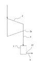
図1に示すように、本実施形態の消音器1は、圧縮機2が吐出する圧縮空気の流れに重畳して伝搬される音波を減衰させるために使用される。そのため、本実施形態の消音器1は、圧縮機2の吐出流路4に配置されている。
(First Embodiment)
As shown in FIG. 1, the
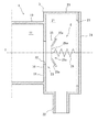
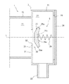
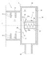
図2に示すように、消音器1は、円管状であって軸線L方向に延びる有限長の誘導管(音響エレメント)10と、軸線L方向から見て誘導管10よりも径が大きい概ね円管状の膨張部20と、これらを流体的に接続する接続部30とを備える。誘導管10と膨張部20と接続部30とは、一体の筐体3で形成されている。なお、本実施形態では筐体3は概ね円管状に形成されているが、例えば多角管状に形成されていてもよい。また、誘導管10と膨張部20と接続部30とは、それぞれ別の部材で構成されてもよい。
As shown in FIG. 2, the
誘導管10は、内部に誘導室11を画定しており、圧縮機2(図1参照)が吐出した圧縮空気を後述する膨張室21まで誘導するための円管である。
The
接続部30は、誘導室11と後述する膨張室21とを仕切る仕切壁31を備える。本実施形態の仕切壁31は筐体3の一部であり、筐体3の内面の一部が軸線Lに向かって突出して形成されている。仕切壁31には、誘導室11と膨張室21とを連通する円形の連通孔32が設けられている。即ち、本実施形態の仕切壁31は、軸線L方向から見て環状に形成されている。
The connecting
膨張部20は、内部に膨張室21を画定しており、軸線L方向とは異なる方向に圧縮空気を吐出するように設けられた吐出口22を有する。本実施形態では吐出口22の吐出方向は、軸線Lに直交する方向であるが、吐出方向はこれに限らず、例えば軸線Lに対して傾斜した方向であってもよい。
The
また、膨張部20において、接続部30と対向する端部には円形の開口部23が設けられている。開口部23は、円板状の蓋体24によって閉塞されている。軸線L方向から見て、蓋体24の外形は、筐体3の外形と概ね同形状である。蓋体24は、着脱可能に筐体3に取り付けられており、例えばねじ止めによって筐体3に取り付けられている。
Further, in the
蓋体24には、連通孔32を閉塞可能な弁体25がばね(付勢部材)26を介して保持されている。接続部30には、仕切壁31の一部によって弁座33が構成されている。即ち、弁座33と、弁体25と、ばね26とから逆止弁5が構成されている。弁体25は、ばね26によって弁座33に向かって付勢されており、弁座33と当接して連通孔32を塞ぐ。
A
弁体25は、周縁部に設けられ、弁座33と当接する部分であって、弁座33に向かって先細る形状を有する環状のテーパ部25aと、テーパ部25aの内側に設けられた円形の平板部25bと、弁座33と対向する面と反対面(蓋体24側の面)に設けられた凹部25cとを備える。以降、弁体25の2つの主面のうち弁座33側の面を表面といい、弁座33と対向する面と反対面(蓋体24側の面)を裏面という。即ち、凹部25cは、弁体25の裏面に設けられている。本実施形態では、平板部25bとテーパ部25aの厚みは同一であり、弁体25は一枚の板状である。従って、弁体25の表面の裏側形状は、裏面の形状と相似形である。
The
また、軸線L方向から見ると、それぞれ円形の連通孔32と平板部25bとは同心に設けられており、連通孔32の径が平板部25bの径よりも大きく形成されている。そのため、逆止弁5が閉じられた状態でも、弁体25の平板部25bは弁座33と当接せず、弁体25のテーパ部25aが弁座33と当接する。
Further, when viewed from the axis L direction, the
また、軸線L方向から見て、本実施形態の弁体25の面積は、膨張室21の断面積の25%程度である。特に、弁体25の面積は、膨張室21の断面積の70%未満であることが好ましい。弁体25の面積が膨張室21の断面積の70%未満である場合、弁体25が音響的に剛の境界とならず、誘導室11において、弁体25へ向かう音波と弁体25で反射した音波の共鳴を抑制できる。
Further, the area of the
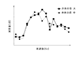
図3に示すように、一般に、弁体25は大きいほど音波の進行を阻害するため、弁体25が大きいほど減音量は大きい。しかし、弁体25を一定以上大きくすると、誘導室11内で弁体25へ向かう音波と弁体25で反射した音波の共鳴が発生し、特定周波数における減音効果の落ち込みが発生する(図3中の矢印参照)。本願発明者は、膨張室21の断面積に対して弁体25の面積が70%以上であるときに、上記共鳴が発生することを見出した。従って、弁体25の面積を膨張室21の断面積の70%未満とすることで、弁体25が剛壁として機能することを防止し、弁体25での音波の反射量を低減させ、この共鳴を抑制できる。これにより、特定周波数における減音効果の落ち込み(図3中の矢印参照)を抑制できる。
As shown in FIG. 3, in general, the larger the
以上の構成から導かれる第1実施形態の消音器1の作用を説明する。
The operation of the
図1および図2を参照して、圧縮機2が作動すると、圧縮機2の吐出口2aから吐出流路4に圧縮空気が吐出され、消音器1に流入する。消音器1内に流入した圧縮空気は、誘導管10内の誘導室11を軸線L方向に接続部30に向かって流れる。次いで、圧縮空気は、接続部30の連通孔32を介して誘導室11から膨張室21に流入する。圧縮空気が膨張室21に流入するとき、逆止弁5は開かれている必要がある。誘導室11と膨張室21の圧力を比較して、誘導室11の圧力が一定以上高い場合、逆止弁5は開かれた状態となり、その逆の場合、逆止弁5は閉じられた状態となる。ここで、逆止弁5が開かれるための両室11,21の圧力差は、ばね26に応じて所望の圧力差に設定される。逆止弁5が開かれた状態で膨張室21に流入した圧縮空気は、軸線Lに直交する方向へ進行方向が曲げられ、吐出口22から吐出流路4に吐出される。
With reference to FIGS. 1 and 2, when the
膨張部20では、誘導管10および吐出口22に対して、大きな流路断面が形成されている。即ち、圧縮空気が連通孔32を介して誘導室11から膨張室21に流入するとき、圧縮空気の流路断面積は大きくなっている。また、圧縮空気が膨張室21から吐出口22を通じて吐出されるとき、圧縮空気の流路断面積は小さくなっている。そのため、この2箇所でインピーダンスが急激に変化し、音波は内部で反射を生じて減衰する。具体的には、誘導室11と膨張室21との境界部および膨張室21と吐出口22との境界部で反射を生じて音波が減衰する。このように、膨張室21を設けることにより流路断面積を変化させ、圧縮空気の流れに重畳して伝搬される音波を減衰させることができる。
In the
本実施形態によれば、逆流抑制機能と消音機能を併せ持つ逆止弁5を有する消音器1を提供でき、従来と比較して省スペースで高い消音効果を得ることができる。具体的には、弁体25が弁座33と当接するとき、テーパ部25aで連通孔32を塞ぐため、連通孔32を正確に塞ぐことができる。仮に、弁体25がテーパ部25aを有しておらず平板部25bで連通孔32を塞ぐ場合、平板部25bの組立公差または製造公差等によっては、弁座33に正確に当接できず、即ち連通孔32を正確に塞ぐことができず、逆止弁5としての機能を果たさないおそれがある。本実施形態の構成では、テーパ部25aによってこの問題を抑制し、圧縮空気の逆流を安定して抑制できる。ここで、逆流とは、膨張室21から連通孔32を通じて誘導室11に圧縮空気がながれることをいう。さらに、弁体25の一部をテーパ状にすることで弁体25の剛性を向上できるため、必要な曲げ剛性を得るための板厚を薄くすることができる。その結果、単なる平板状の場合と比べて弁体25を軽量化でき、コストダウンとなる。また、弁体25がテーパ部25aで弁座33と当接することで、平板部25bで当接する場合と比べて圧縮空気の流路が徐々に広がるため、圧力損失の増大を抑制できる。また、逆止弁5がばねを備えることで、ばね26の上流側(誘導室11側)の圧力が下流側(膨張室21側)よりも一定以上高い場合にのみ逆止弁5が開く。即ち、ばね26によって簡易に逆流抑制機能を実現できる。また、弁体25が裏面に凹部25cを有することで、連通孔32を通過した圧縮空気に重畳した音波が凹部25cに回り込む回折現象が生じる。そのため、音波の回折減衰による減音効果を得ることができる。また、弁体25を保持する面と吐出口22を有する面とが異なっているため、吐出口22以外から弁体25にアクセスできる。そのため、例えば吐出口22以降に配管を設けた場合でも配管を取り外すことなく、逆止弁5のメンテナンスが可能である。このように逆止弁5を効率的にメンテナンスするためには、吐出口22以外から逆止弁5に対して外部からアクセス可能なように膨張部20に吐出口22以外の開口部23を本実施形態のようにして設けることが好ましい。
According to the present embodiment, it is possible to provide a
また、図4に示す第1変形例のように、弁体25は板状でなく、ブロック状であってもよい。即ち、弁体25の厚みは限定されない。本変形例では、第1実施形態と同様に、弁体25の表面の裏側形状は、裏面の形状と相似形である。
Further, as in the first modification shown in FIG. 4, the
また、図5に示す第2変形例のように、弁体25の裏面の凹部25cは、球面の一部であってもよい。さらに言えば、凹部25cの態様は特に限定されず、上記の回折減衰が生じる態様であればよい。
Further, as in the second modification shown in FIG. 5, the
(第2実施形態)
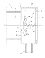
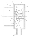
図6は、第2実施形態に係る消音器1の模式的な側面断面図である。本実施形態の消音器1では、規制部材27以外の構成は図2の第1実施形態と同様である。従って、図2に示した構成と同様の部分については同様の符号を付して説明を省略する。
(Second Embodiment)
FIG. 6 is a schematic side sectional view of the
本実施形態の消音器1は、逆止弁5の開度を規制する規制部材27をさらに備える。規制部材27は、軸線L方向から見て、ばね26を囲繞して設けられている。規制部材27は、蓋体24の一部が円筒状に軸線Lを中心に突出して形成されている。即ち、規制部材27は連通孔32と同心に設けられている。さらに詳細には、規制部材27は、弁体25を挟んで弁座33と反対側(蓋体24側)に設けられている。また、弁体25は、吐出口22に向かって規制部材27よりも突出している。弁体25がばね26の付勢に抗して弁座33から離れる方向に移動すると、弁体25の裏面が規制部材27に当接し、弁体25の移動が規制される。軸線L方向から見て、規制部材27の径は、弁体25のテーパ部25aの径よりも小さい。また、規制部材27の長さは、逆止弁5が最大に開いたときでも、連通孔32と吐出口22とを直線的に結ぶ空間S内に弁体25の少なくとも一部が配置されるような長さである。なお、図6は、逆止弁5が最大まで開いたときの状態を示している。
The
本実施形態によれば、規制部材27により逆止弁5の最大開度を規制できるため、消音効果が著しく弱まることを防止できる。具体的には、逆止弁5の開度が大きくなると、弁体25と干渉せずに吐出口22まで通過する音波が増えるため、弁体25による音波の減衰量が小さくなる。即ち、弁体25が弁座33に近い位置にあるほど、大きな消音効果を期待できる。本実施形態では、逆止弁5の最大開度が規制されているため、最大開度においても所定の減衰量を確保できる。所定の減衰量は規制部材27によって規制される逆止弁5の最大開度に応じて変化するが、これは許容される騒音の音量に応じて決定されればよい。
According to the present embodiment, since the maximum opening degree of the
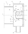
また、弁体25が規制部材27よりも吐出口22に向かって突出しているため、弁体25を挟んで規制部材27側から弁座33側へと向かう音波の伝搬を阻害する(図6の破線矢印参照)。従って、この阻害により音波が減衰されるため、消音器1としての減音効果を高めることができる。これに対し、図7に示す比較例のように、弁体25が規制部材27よりも吐出口22に向かって突出していない場合、図6に示す場合のように弁体25を挟んで規制部材27側から弁座33側へと向かう音波の伝搬を阻害できない。従って、消音器1としての減音効果を高めることができない。
Further, since the
また、逆止弁5が最大に開いたときでも、連通孔32と吐出口22とを直線的に結ぶ空間S内に弁体25の少なくとも一部が配置されているため、膨張室21の入口(連通孔32)から膨張室21の出口(吐出口22)に向かう音波に弁体25が干渉し、より確実に回折減衰による減音効果を得ることができる。
Further, even when the
(第3実施形態)
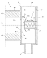
図8は、第3実施形態に係る消音器1の模式的な側面断面図である。本実施形態の消音器1では、誘導室11内に共鳴防止構造が設けられている以外の構成は図6の第2実施形態と同様である。従って、図6に示した構成と同様の部分については同様の符号を付して説明を省略する。
(Third Embodiment)
FIG. 8 is a schematic side sectional view of the
本実施形態では、共鳴防止構造として、誘導室11内に吸音材12が配置されている。吸音材12は、例えばグラスウールやロックウールなどの多孔質材料からなり、誘導管10の内側面に貼り付けられている。これに加えて、使用環境が高温の場合には、鉄やステンレス等の金属繊維材料を吸音材12として使用してもよい。
In the present embodiment, the
本実施形態によれば、共鳴防止構造として吸音材12を設けたことにより、誘導管10内における共鳴を抑制し、特定周波数における消音効果の落ち込みを抑制できる。これにより、弁体25の形状によらず、共鳴を抑制できる。従って、弁体25を共鳴の有無によらず大きく好適に設計できる。なお、本実施形態では、誘導管10と吸音材12によって音響エレメントが構成されている。
According to the present embodiment, by providing the
また、図9に示す変形例のように、共鳴防止構造として、上記吸音材12に代えて複数のヒダ状の突出部13が設けられてもよい。突出部13は、誘導管10の内面から軸線Lに向かって突出している。突出部13は、軸線L方向から見ると、円形状の平板の中央に貫通孔が設けられた形状となっている。なお、本変形例では、突出部13を含む誘導管10によって音響エレメントが構成されている。
Further, as in the modified example shown in FIG. 9, as the resonance prevention structure, a plurality of fold-shaped
以上より、本発明の具体的な実施形態やその変形例について説明したが、本発明は上記形態に限定されるものではなく、この発明の範囲内で種々変更して実施することができる。例えば、個々の実施形態の内容を適宜組み合わせたものを、この発明の一実施形態としてもよい。 Although specific embodiments of the present invention and variations thereof have been described above, the present invention is not limited to the above embodiments, and various modifications can be made within the scope of the present invention. For example, an embodiment of the present invention may be a combination of the contents of the individual embodiments as appropriate.
1 消音器
2 圧縮機
2a 吐出口
3 筐体
4 吐出流路
5 逆止弁
10 誘導管(音響エレメント)
11 誘導室
12 吸音材(音響エレメント)
13 突出部(音響エレメント)
20 膨張部
21 膨張室
22 吐出口
23 開口部
24 蓋体
25 弁体
25a テーパ部
25b 平板部
25c 凹部
26 ばね(付勢部材)
27 規制部材
30 接続部
31 仕切壁
32 連通孔
33 弁座
1
11
13 Protruding part (acoustic element)
20
27
Claims (8)
内部に誘導室を画定する有限長の誘導管を有する音響エレメントと、
前記膨張室と前記誘導室とを連通する連通孔が設けられた接続部と、
前記誘導室から前記連通孔を通って前記膨張室へと流れる流体が逆流することを防止するための逆止弁と
を備える消音器であって、
前記逆止弁は、前記接続部に設けられた弁座と、前記弁座と当接して前記連通孔を塞ぐ弁体と、前記弁体を前記弁座に向かって付勢する付勢部材とを備え、
前記弁体は、当該弁体の周縁部であり、前記弁座と辺接触の態様で当接する部分であって、前記弁座に向かって先細る形状を有するテーパ部と、前記テーパ部の内側に設けられた平板部と、前記弁座と対向する面と反対面において前記テーパ部と前記平板部とによって画定されるとともに前記弁座に向かって先細る形状を有する凹部とを備える、消音器。 An expansion part that has a discharge port and defines an expansion chamber inside,
An acoustic element with a finite length guide tube that defines the guide chamber inside,
A connection portion provided with a communication hole that communicates the expansion chamber and the guide chamber,
A silencer provided with a check valve for preventing the fluid flowing from the induction chamber to the expansion chamber through the communication hole from flowing back.
The check valve includes a valve seat provided at the connection portion, a valve body that contacts the valve seat and closes the communication hole, and an urging member that urges the valve body toward the valve seat. With
The valve body is a peripheral portion of the valve body, a portion that comes into contact with the valve seat in a side contact manner, and has a tapered portion having a shape that tapers toward the valve seat and the inside of the tapered portion. comprising a flat portion provided, and a recess having a tapering shape toward the valve seat while being defined by the said plate and Oite the tapered portion on the opposite surface and the valve seat surface facing to, Silencer.
前記弁体は、前記吐出口に向かって前記規制部材よりも突出している、請求項2に記載の消音器。 The regulating member is provided on the side opposite to the valve seat with the valve body interposed therebetween.
The silencer according to claim 2, wherein the valve body protrudes from the regulating member toward the discharge port.
Priority Applications (4)
| Application Number | Priority Date | Filing Date | Title |
|---|---|---|---|
| JP2016219101A JP6830795B2 (en) | 2016-11-09 | 2016-11-09 | Silencer |
| PCT/JP2017/038801 WO2018088231A1 (en) | 2016-11-09 | 2017-10-26 | Muffler |
| CN201780068827.8A CN109923310B (en) | 2016-11-09 | 2017-10-26 | Noise silencer |
| TW106138022A TWI659148B (en) | 2016-11-09 | 2017-11-03 | Silencer |
Applications Claiming Priority (1)
| Application Number | Priority Date | Filing Date | Title |
|---|---|---|---|
| JP2016219101A JP6830795B2 (en) | 2016-11-09 | 2016-11-09 | Silencer |
Publications (2)
| Publication Number | Publication Date |
|---|---|
| JP2018076822A JP2018076822A (en) | 2018-05-17 |
| JP6830795B2 true JP6830795B2 (en) | 2021-02-17 |
Family
ID=62109474
Family Applications (1)
| Application Number | Title | Priority Date | Filing Date |
|---|---|---|---|
| JP2016219101A Active JP6830795B2 (en) | 2016-11-09 | 2016-11-09 | Silencer |
Country Status (4)
| Country | Link |
|---|---|
| JP (1) | JP6830795B2 (en) |
| CN (1) | CN109923310B (en) |
| TW (1) | TWI659148B (en) |
| WO (1) | WO2018088231A1 (en) |
Families Citing this family (2)
| Publication number | Priority date | Publication date | Assignee | Title |
|---|---|---|---|---|
| CN111971147B (en) | 2018-04-12 | 2022-06-24 | 住友电工硬质合金株式会社 | Trimmer |
| CN112196638A (en) * | 2020-09-29 | 2021-01-08 | 艾瑞鸿泰(上海)汽车技术有限公司 | Rebound reed type noise reduction valve of exhaust system |
Family Cites Families (7)
| Publication number | Priority date | Publication date | Assignee | Title |
|---|---|---|---|---|
| DE2619516C3 (en) * | 1976-05-03 | 1979-02-15 | Siemens Ag, 1000 Berlin Und 8000 Muenchen | Automatic valve for a pump for conveying gaseous and / or liquid helium |
| DE2821255C2 (en) * | 1978-05-16 | 1987-04-30 | Mokveld Valves B.V., Gouda | check valve |
| JPH0355822Y2 (en) * | 1985-02-04 | 1991-12-12 | ||
| JP2001280254A (en) * | 2000-03-31 | 2001-10-10 | Daikin Ind Ltd | Compressor for refrigeration equipment |
| JP2010249292A (en) * | 2009-04-20 | 2010-11-04 | Chugoku Electric Power Co Inc:The | Check valve with leak function |
| CN203823166U (en) * | 2014-04-03 | 2014-09-10 | 北京思瑞德医疗器械有限公司 | Safety valve |
| JP6659234B2 (en) * | 2014-05-30 | 2020-03-04 | 株式会社神戸製鋼所 | Silencer |
-
2016
- 2016-11-09 JP JP2016219101A patent/JP6830795B2/en active Active
-
2017
- 2017-10-26 WO PCT/JP2017/038801 patent/WO2018088231A1/en not_active Ceased
- 2017-10-26 CN CN201780068827.8A patent/CN109923310B/en active Active
- 2017-11-03 TW TW106138022A patent/TWI659148B/en active
Also Published As
| Publication number | Publication date |
|---|---|
| CN109923310B (en) | 2021-06-04 |
| JP2018076822A (en) | 2018-05-17 |
| CN109923310A (en) | 2019-06-21 |
| WO2018088231A1 (en) | 2018-05-17 |
| TWI659148B (en) | 2019-05-11 |
| TW201821688A (en) | 2018-06-16 |
Similar Documents
| Publication | Publication Date | Title |
|---|---|---|
| TWI635218B (en) | Silencer | |
| JP5404387B2 (en) | Resonator in acoustic muffler for cooling compressor | |
| KR101114394B1 (en) | Variable muffler | |
| CN204716496U (en) | Expansion chamber for the discharge line of an alternating compressor | |
| JP4976046B2 (en) | A silencer configured and intended for compressors | |
| JP2011508141A (en) | A system to dampen vibrations in cooling compressor gas emissions. | |
| JP4365386B2 (en) | Refrigerant compressor | |
| JP6830795B2 (en) | Silencer | |
| CN107208508B (en) | silencer | |
| CN110043346A (en) | Exhaust throttle pipe for Vehicular silencer | |
| US20060086563A1 (en) | Compressor discharge pulsation dampener | |
| CN103180614B (en) | Manual selective attenuator | |
| JP2025518948A (en) | Inlet silencer for positive displacement compressor and positive displacement compressor equipped with same | |
| WO2019032681A1 (en) | A muffler for a refrigeration system and the refrigeration system | |
| CN116335938A (en) | Screw compressors | |
| JP4684237B2 (en) | Discharge system for compressor | |
| JP2008169781A (en) | Exhaust muffling device | |
| KR102762021B1 (en) | Pressure safety valve | |
| KR20260046220A (en) | Expansion chamber for a compressor device and a compressor device having such an expansion chamber | |
| KR20060058261A (en) | Muffler Variable Valve | |
| JP2006125238A (en) | Muffler for internal combustion engine | |
| CN112855623A (en) | Vibration damper for condenser | |
| JPH03279695A (en) | Rotary hermetic compressor | |
| JP2009127716A (en) | Quick closing check valve with noise elimination function | |
| WO2015029755A1 (en) | Screw compressor |
Legal Events
| Date | Code | Title | Description |
|---|---|---|---|
| A621 | Written request for application examination |
Free format text: JAPANESE INTERMEDIATE CODE: A621 Effective date: 20181203 |
|
| A131 | Notification of reasons for refusal |
Free format text: JAPANESE INTERMEDIATE CODE: A131 Effective date: 20191210 |
|
| A131 | Notification of reasons for refusal |
Free format text: JAPANESE INTERMEDIATE CODE: A131 Effective date: 20200623 |
|
| A521 | Written amendment |
Free format text: JAPANESE INTERMEDIATE CODE: A523 Effective date: 20200820 |
|
| A131 | Notification of reasons for refusal |
Free format text: JAPANESE INTERMEDIATE CODE: A131 Effective date: 20200908 |
|
| A601 | Written request for extension of time |
Free format text: JAPANESE INTERMEDIATE CODE: A601 Effective date: 20201104 |
|
| A521 | Written amendment |
Free format text: JAPANESE INTERMEDIATE CODE: A523 Effective date: 20201217 |
|
| TRDD | Decision of grant or rejection written | ||
| A01 | Written decision to grant a patent or to grant a registration (utility model) |
Free format text: JAPANESE INTERMEDIATE CODE: A01 Effective date: 20210119 |
|
| A61 | First payment of annual fees (during grant procedure) |
Free format text: JAPANESE INTERMEDIATE CODE: A61 Effective date: 20210127 |
|
| R151 | Written notification of patent or utility model registration |
Ref document number: 6830795 Country of ref document: JP Free format text: JAPANESE INTERMEDIATE CODE: R151 |
|
| S111 | Request for change of ownership or part of ownership |
Free format text: JAPANESE INTERMEDIATE CODE: R313111 |
|
| R350 | Written notification of registration of transfer |
Free format text: JAPANESE INTERMEDIATE CODE: R350 |