JP6830995B2 - liner - Google Patents
liner Download PDFInfo
- Publication number
- JP6830995B2 JP6830995B2 JP2019232571A JP2019232571A JP6830995B2 JP 6830995 B2 JP6830995 B2 JP 6830995B2 JP 2019232571 A JP2019232571 A JP 2019232571A JP 2019232571 A JP2019232571 A JP 2019232571A JP 6830995 B2 JP6830995 B2 JP 6830995B2
- Authority
- JP
- Japan
- Prior art keywords
- liner
- shell
- transition point
- lock
- tangential
- Prior art date
- Legal status (The legal status is an assumption and is not a legal conclusion. Google has not performed a legal analysis and makes no representation as to the accuracy of the status listed.)
- Active
Links
Images


Classifications
-
- A—HUMAN NECESSITIES
- A61—MEDICAL OR VETERINARY SCIENCE; HYGIENE
- A61F—FILTERS IMPLANTABLE INTO BLOOD VESSELS; PROSTHESES; DEVICES PROVIDING PATENCY TO, OR PREVENTING COLLAPSING OF, TUBULAR STRUCTURES OF THE BODY, e.g. STENTS; ORTHOPAEDIC, NURSING OR CONTRACEPTIVE DEVICES; FOMENTATION; TREATMENT OR PROTECTION OF EYES OR EARS; BANDAGES, DRESSINGS OR ABSORBENT PADS; FIRST-AID KITS
- A61F2/00—Filters implantable into blood vessels; Prostheses, i.e. artificial substitutes or replacements for parts of the body; Appliances for connecting them with the body; Devices providing patency to, or preventing collapsing of, tubular structures of the body, e.g. stents
- A61F2/02—Prostheses implantable into the body
- A61F2/30—Joints
- A61F2/32—Joints for the hip
- A61F2/34—Acetabular cups
-
- A—HUMAN NECESSITIES
- A61—MEDICAL OR VETERINARY SCIENCE; HYGIENE
- A61F—FILTERS IMPLANTABLE INTO BLOOD VESSELS; PROSTHESES; DEVICES PROVIDING PATENCY TO, OR PREVENTING COLLAPSING OF, TUBULAR STRUCTURES OF THE BODY, e.g. STENTS; ORTHOPAEDIC, NURSING OR CONTRACEPTIVE DEVICES; FOMENTATION; TREATMENT OR PROTECTION OF EYES OR EARS; BANDAGES, DRESSINGS OR ABSORBENT PADS; FIRST-AID KITS
- A61F2/00—Filters implantable into blood vessels; Prostheses, i.e. artificial substitutes or replacements for parts of the body; Appliances for connecting them with the body; Devices providing patency to, or preventing collapsing of, tubular structures of the body, e.g. stents
- A61F2/02—Prostheses implantable into the body
- A61F2/30—Joints
- A61F2002/30001—Additional features of subject-matter classified in A61F2/28, A61F2/30 and subgroups thereof
Landscapes
- Health & Medical Sciences (AREA)
- Orthopedic Medicine & Surgery (AREA)
- Cardiology (AREA)
- Oral & Maxillofacial Surgery (AREA)
- Transplantation (AREA)
- Engineering & Computer Science (AREA)
- Biomedical Technology (AREA)
- Heart & Thoracic Surgery (AREA)
- Vascular Medicine (AREA)
- Life Sciences & Earth Sciences (AREA)
- Animal Behavior & Ethology (AREA)
- General Health & Medical Sciences (AREA)
- Public Health (AREA)
- Veterinary Medicine (AREA)
- Prostheses (AREA)
- Surgical Instruments (AREA)
Description
本発明は、概して、整形外科手術に使用されるインプラントに関する。 The present invention generally relates to implants used in orthopedic surgery.
ヒト身体内の関節は、2つ以上の骨又は他の骨格部分の間の接合部を形成する。足首、腰、膝、肩、肘及び手首は、身体内に見出される多数の関節のうちのわずかな例である。上記の関節のリストから明かとなるように、関節の多くは骨間の相対的な動作を可能にする。例えば、関節は、摺動、滑動、蝶番の運動、又は球状動作を有し得る。例えば、足首は蝶番動作を可能にし、膝は滑動動作と蝶番動作とを組み合わせることができ、肩及び腰は、球状配置による動作を可能にする。 Joints within the human body form joints between two or more bones or other skeletal parts. The ankles, hips, knees, shoulders, elbows and wrists are just a few of the many joints found in the body. As evidenced by the list of joints above, many joints allow relative movement between bones. For example, joints can have sliding, sliding, hinge movements, or spherical movements. For example, the ankles allow for hinged movements, the knees allow for a combination of sliding and hinged movements, and the shoulders and hips allow for spherical movements.
身体内の関節は、応力が加えられ、又は多様な方法で損傷される場合がある。例えば、長年に亘る関節の継続した使用により、関節上に漸進的な磨耗及び断裂が与えられる。運動を可能にする関節は、骨間に配置されている軟骨を有し、この軟骨は運動に潤滑を提供し、また関節に指向される力の幾分かを吸収する。時間の経過と共に、関節の通常の使用により軟骨が磨耗し、動作する骨同士の直接接触がもたらされる場合がある。対称的に、通常の使用における関節に対する外傷、例えば自動車事故などの事故による大きい力の供給が、骨、軟骨又は腱若しくは靱帯などの他の結合組織に対する相当な損傷の原因となり得る。 Joints in the body can be stressed or damaged in a variety of ways. For example, long-term continuous use of a joint results in gradual wear and tear on the joint. The joints that allow movement have cartilage that is located between the bones, which lubricate the movement and also absorb some of the force directed at the joint. Over time, normal use of joints can cause cartilage to wear, resulting in direct contact between moving bones. In contrast, trauma to joints in normal use, such as the high force supply from an accident such as a car accident, can cause considerable damage to bone, cartilage or other connective tissue such as tendons or ligaments.
関節の疾病を指す用語である関節症は、関節が損傷した状態となり得る他の一手段である。おそらく最も知られている関節疾病は関節炎であり、関節炎は一般に、疼痛、肥大、硬直、不安定性、及び多くの場合、変形をもたらす関節の疾病又は炎症と称されている。 Arthropathy, a term that refers to joint disease, is another means by which joints can become injured. Perhaps the most well-known joint disease is arthritis, which is commonly referred to as joint disease or inflammation that results in pain, hypertrophy, stiffness, instability, and often deformity.
多数の異なる形態の関節炎が存在し、変形性関節症は最も一般的であり、この変形性関節症は、関節内の軟骨の摩耗及び断裂から生じる。他のタイプの関節炎は骨壊死であり、骨壊死は、血液供給の損失による骨の一部の死を原因とする。他のタイプの関節炎は関節に対する外傷を原因とし、一方、関節リウマチ、ループス及び乾癬性関節炎などの他の関節炎は、軟骨を破壊し、関節の内張りの炎症に関連する。 There are many different forms of arthritis, and osteoarthritis is the most common, which results from wear and tear of cartilage in the joints. Another type of arthritis is osteonecrosis, which results in the death of part of the bone due to a loss of blood supply. Other types of arthritis cause trauma to the joints, while other arthritis such as rheumatoid arthritis, lupus and psoriatic arthritis destroy cartilage and are associated with inflammation of the joint lining.
股関節は、一般に関節症に罹患する関節の1つである。股関節は、腿骨又は大腿骨を骨盤と連結する球状関節である。骨盤は、大腿骨内の球状頭部を受容するための、寛骨臼と称される半球形のソケットを有する。大腿骨頭と寛骨臼の両方は軟骨で被覆されて、大腿骨が骨盤内で容易に動作することを可能にしている。一般に関節症に罹患する他の関節には、脊椎、膝、肩、手根、中手、及び手の指骨が挙げられる。関節症に対立するものとして、関節形成術は、一般に人工関節の作製を指す。疼痛が激しい場合、又は関節の可動範囲が制限される場合などの、関節炎又は他の形態の関節症のいくつかのケースでは、人工関節内の関節の部分的又は全体的な置き換えが正当とされる場合がある。関節置き換えの手順は、勿論、問題の特定の関節によって様々であるが、一般的には、罹患した骨の終端部分を人工関節インプラントで置き換え、軟骨の代用品として機能する部材を挿入することを含む。 The hip joint is one of the joints that generally suffers from arthropathy. The hip joint is a spherical joint that connects the femur or femur to the pelvis. The pelvis has a hemispherical socket called the acetabulum to receive the spherical head within the femur. Both the femoral head and the acetabulum are covered with cartilage, allowing the femur to move easily within the pelvis. Other joints commonly suffering from arthropathy include the spine, knees, shoulders, carpals, middle hands, and phalanges of the hands. As opposed to arthropathy, arthroplasty generally refers to the production of artificial joints. In some cases of arthritis or other forms of arthropathy, such as when the pain is severe or when the range of motion of the joint is restricted, partial or total replacement of the joint within the prosthesis is justified. May occur. The procedure for joint replacement will, of course, vary depending on the particular joint in question, but it is common to replace the end of the affected bone with an artificial joint implant and insert a member that acts as a cartilage substitute. Including.
人工関節インプラントは、骨と結合した状態となり、関節に強度及び剛性を提供する剛性材料から形成され、軟骨代用部材は、関節に潤滑を提供し、圧縮力の幾分かを吸収するように選定される。インプラントに好適な材料には、チタン、コバルトクロム、ステンレス鋼、セラミックなどの金属及び複合材料が挙げられ、軟骨代用品に好適な材料には、ポリエチレンが挙げられる。人工関節インプラントを宿主骨に固定するために、セメントも使用し得る。 Artificial joint implants are formed from rigid materials that are attached to the bone and provide strength and rigidity to the joint, and cartilage replacement members are selected to provide lubrication to the joint and absorb some of the compressive force. Will be done. Suitable materials for implants include metals and composite materials such as titanium, cobalt chrome, stainless steel and ceramics, and suitable materials for cartilage substitutes include polyethylene. Cement may also be used to secure the prosthesis implant to the host bone.
例えば、股関節全置換は、ボール形状の大腿骨頭を除去し、髄質の管又は骨髄と称される骨の中央内にステムインプラントを挿入することを含む。ステムインプラントは、髄質の管内にセメントで接着されてもよく、又は多孔質被覆表面を有して、インプラントに対して骨を直接治癒させてもよい。ステムインプラントは、健康な大腿骨の首部及びボール形状の頭部と同一の機能を遂行することが意図される首部及びボール形状の頭部を有する。 For example, total hip replacement involves removing the ball-shaped femoral head and inserting a stem implant into the center of the bone called the medullary canal or bone marrow. The stem implant may be cemented into the medullary canal or may have a porous coated surface to heal the bone directly to the implant. Stem implants have a neck and ball-shaped head that are intended to perform the same functions as a healthy femoral neck and ball-shaped head.
カップ又はシェルは、寛骨臼内に直接配置されてもよい。カップ又はシェルは、骨の内殖を促進するための多孔質コーティングを含んで、シェルを寛骨臼に固定し得る。代替的に、又は付加的に、シェルは骨ねじを受容するための1つ又は複数の開口部を含んで、シェルが寛骨臼に付着すること補助してもよい。カップは、金属、例えば、コバルトクロム、ステンレス鋼又はチタンから形成されてもよい。代替的に、カップは、セラミック又はポリエチレンから形成されてもよい。いくつかの実施形態において、カップは、頭部に直接係合する。別の実施形態では、ある種のライナーがカップ内に挿入されて、頭部に対して関節をなす。ライナーは、金属、セラミック又はポリエチレンから形成されてもよい。 The cup or shell may be placed directly within the acetabulum. The cup or shell may include a porous coating to promote bone endogeneity and secure the shell to the acetabulum. Alternatively or additionally, the shell may include one or more openings to receive the bone screw to assist the shell in attaching to the acetabulum. The cup may be made of a metal such as cobalt chrome, stainless steel or titanium. Alternatively, the cup may be made of ceramic or polyethylene. In some embodiments, the cup engages directly with the head. In another embodiment, some liner is inserted into the cup and articulated with respect to the head. The liner may be made of metal, ceramic or polyethylene.
金属及びセラミックのライナーは、多くの場合、テーパロックを通してシェル内にロックされ、即ち、シェルはテーパを含み、ライナーは、シェルのテーパ内に嵌まり込む対応するテーパを含む。適切に納められた場合、シェルのテーパとライナーのテーパとが互いに係合し、ライナーをシェル内にロックする。しかしながら、挿入中に、ライナーの円錐テーパがシェルの円錐テーパと心ずれした状態となり得るため、意図される円錐テーパの表面対表面のロックが阻止される。これはクロスロッキングと称され、比較的安定性が低い端部、又は多地点ロックにより特徴付けられる。挿入中に心ずれが生じた場合、手術中に、インプラントの破壊及び他の合併症の危険性が増大する。 Metal and ceramic liners are often locked into the shell through a taper lock, i.e. the shell contains a taper and the liner contains a corresponding taper that fits within the taper of the shell. When properly seated, the shell taper and liner taper engage with each other, locking the liner into the shell. However, during insertion, the conical taper of the liner can be misaligned with the conical taper of the shell, thus preventing surface-to-surface locking of the intended conical taper. This is called cross-locking and is characterized by relatively less stable edges, or multipoint locking. If misalignment occurs during insertion, the risk of implant destruction and other complications increases during surgery.
ライナーがクロスロックキング状態となった場合、外科医は、ライナーをクロスロッキング位置に残留させるか、又はライナーをシェルから除去するよう試みるか、又はインプラント構造体全体を除去するかを決定する必要がある。クロスロッキングしたライナーをシェル内に残留させることは、摩耗の増大、インプラント構造体の分解、最適ではない運動範囲、及びインプラント破壊を含む多数の危険性を患者に与える。ライナーをシェルから除去し又は構造体全体を除去することもまた、危険性をもたらし、手術を複雑化させる。 If the liner becomes cross-locking, the surgeon must decide whether to leave the liner in the cross-locking position, attempt to remove the liner from the shell, or remove the entire implant structure. .. Retaining the cross-locked liner in the shell poses a number of risks to the patient, including increased wear, disassembly of the implant structure, suboptimal range of motion, and implant destruction. Removing the liner from the shell or removing the entire structure also poses a risk and complicates surgery.
したがって、クロスロッキングしたテーパ接合の発生を除去し、又は概ね低下させるライナーが必要とされている。 Therefore, there is a need for a liner that eliminates or generally reduces the occurrence of cross-locked tapered joints.
本発明の一実施形態によれば、股関節形成術に使用される寛骨臼シェル内に挿入されるように適合されたライナーを提供する。ライナーは、大腿骨頭に係合するように適合された凹状の内側表面を含む。ライナーは、更に寛骨臼シェルに係合するように適合された外側表面と、内側表面と外側表面との間に延びる縁部と、を含む。外側表面は、縁部から延びるロック部分と、第1の推移地点においてロック部分から延びる複合曲線状部分と、複合曲線状部分から延びるドーム部分と、を含み、第1の推移地点において、複合曲線状部分は、ロック部分に対して接線をなす。 According to one embodiment of the invention, there is provided a liner adapted to be inserted into the acetabular shell used in hip arthroplasty. The liner includes a concave medial surface adapted to engage the femoral head. The liner further includes an outer surface adapted to engage the acetabular shell and an edge extending between the medial and lateral surfaces. The outer surface includes a lock portion extending from the edge, a composite curved portion extending from the lock portion at the first transition point, and a dome portion extending from the composite curved portion, and the composite curve at the first transition point. The shaped part forms a tangent to the lock part.
別の実施形態では、関節形成術に使用されるキットを提供する。キッドは、シェルと、シェル内に挿入されるように適合されたライナーと、を含む。ライナーは、内側表面及び外側表面を含む。内側表面は略凹状であり、外側表面は寛骨臼シェルに係合するように適合されている。外側表面は、ロック部分及び複合曲線状部分を含み、複合曲線状部分は、放射状部分及び直線接線部分を含む。 In another embodiment, a kit used for arthroplasty is provided. The kid includes a shell and a liner adapted to be inserted into the shell. The liner includes an inner surface and an outer surface. The medial surface is substantially concave and the lateral surface is adapted to engage the acetabular shell. The outer surface includes a lock portion and a composite curved portion, and the composite curved portion includes a radial portion and a straight tangential portion.
本発明の更に別の実施形態では、ライナーを提供する。ライナーは関節形成術に使用され、内側表面及び外側表面を含む。外側表面は、寛骨臼シェルに係合するように適合され、ロック部分及び複合曲線状部分を含む。複合曲線状部分は、ロック部分から接線方向に延びる。 Yet another embodiment of the present invention provides a liner. Liners are used in arthroplasty and include medial and lateral surfaces. The lateral surface is adapted to engage the acetabular shell and includes a locking portion and a compound curved portion. The compound curved portion extends tangentially from the lock portion.
本発明及びその利点をより完全に理解するために、ここで添付の図面と共に以下の説明を参照することにする。
本発明の実施形態及びその利点は、以下の説明及び図面を参照することにより最良に理解される。以下の説明及び図面において、同様の参照符号が、図面の同様の部分及び対応する部分に対して用いられている。 The embodiments of the present invention and their advantages are best understood by reference to the following description and drawings. In the following description and drawings, similar reference numerals are used for similar and corresponding parts of the drawings.
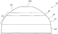
ここで図1及び2を参照すると、本発明の一つの実施形態によるライナー10が示されている。ライナー10は、内側表面(即ち支持表面)12を含む。図示するように、本実施形態において支持表面12は略凹状である。支持表面12は、大腿骨頭(図示せず)と関節をなすように設計されている。ライナー10は、外側表面14も含む。外側表面14は、シェル16(図5及び6)内に嵌まり込むように設計されている。支持表面12及び外側表面14は、支持表面12と外側表面14との間に延びる縁部18に結合する。換言すれば、縁部18は、支持表面12と外側表面14との間にある。本実施形態では、支持表面12、外側表面14及び縁部18は全て、単一部品から形成されている。別の実施形態では、これらの部品は、モジュール式であり、共にロックされてもよい。
Here, with reference to FIGS. 1 and 2, a
尚、図1及び2を参照して、外側表面14をより詳細に説明する。外側表面14は、ロック部分20、複合曲線状部分22及びドーム部分24を含む。本実施形態では、ドーム部分24は、先行技術によるいくつかのライナー設計に一般的であるように、平坦な頂部部分24aを含む。しかしながら、いくつかのライナー10では、平坦な頂部部分が存在しなくてもよいことを理解するべきである。ロック部分20は縁部18から延び、以下により詳細に記載するように、シェル16に係合する寸法及び形状を有する。本実施形態では、ロック部分20は円錐テーパ形状の壁であるが、既知の他のロック機構を使用してもよい。
The
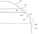
図1及び2に図示した本実施形態では、複合曲線状部分22は、放射状部分25及び接線部分26の2つの部分を含む。図示した実施形態では、放射状部分は曲線状であり、接線部分26は直線である。別の実施形態では、接線部分26も、放射状部分の半径とは異なる半径を有する曲線状であってもよい。複合曲線状部分22の付近のライナー10の拡大図である図3に示すように、ロック部分20は、推移地点28において放射状部分25に対して接線をなす。換言すれば、放射状部分25は、ロック部分20から接線方向に延びる。放射状部分25がロック部分20に対して接線をなすため、端部が存在せず、ロック部分20と放射状部分25との間に連続性が存在する。放射状部分25は、ロック部分20に対して接線をなす、円の半径を有する曲線状であるため、その中心を画定している。
In the present embodiment illustrated in FIGS. 1 and 2, the composite
図2に示すように、複合曲線状部分22は、ロック部分20が終焉する地点から出発し、ロック部分20から延びる。いくつかの実施形態では、ドーム部分24は存在せず、複合曲線状部分22は、ライナー10の頂部まで延びる。
As shown in FIG. 2, the composite
ここで図3を再び参照すると、放射状部分25は、推移地点30において、接線部分26内へと接線方向に移行する。換言すれば、接線部分26は、推移地点30において放射状部分25から接線方向に延びる。放射状部分25は、地点30において接線部分と接線をなし、したがって、ライナー10上には端部又は鋭い地点が存在しない。接線部分26は、推移地点32においてドーム部分24に対しても接線をなす直線である。換言すれば、接線部分26は、放射状部分25及びドーム部分24の両方に対して接線をなす直線である。これら2つの曲線状範囲24、25の両方に対して接線をなす接線部分26を有することにより、端部又は角部が存在せず、粗い表面が減少する。接線部分26は、図1〜3に示す本実施形態では直線である。別の実施形態では、接線部分26は、曲線状であってもよい。更に別の実施形態では、更に図7に示すように、接線部分が存在しなくてもよい。複合曲線状部分22は、放射状部分25のみを含んでもよい。
Here, referring to FIG. 3 again, the
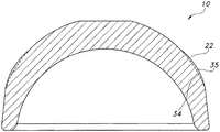
図4を見ると、ライナー10が先行技術によるライナー(線34)上に重ね合わされて示されている。理解し得るように、複合曲線状部分22は、先行技術によるライナーの対応する外側部分34から外方向に延びる。この追加の材料は、図4にて非網掛け部分35により表される。ライナー10中の追加の材料は、下記の図5及び6にて更に説明するように、ライナー10とシェル16とが組立てられた際に、2つの部品の間のすきまの量を低減する。
Looking at FIG. 4, the
いくつかの実施形態において、放射状部分25の曲率は、放射状部分25の半径を最大にすることにより決定されるが、放射状部分25及びドーム部分24の両方に対して接線をなす接線部分26は尚形成できる。しかしながら、別の実施形態では、他のパラメーターが放射状部分25の曲率を決定してもよい。
In some embodiments, the curvature of the
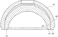
ここで図5及び6を参照すると、シェル16内に挿入されているライナー10が示されている。シェル16は、内側表面36及び外側表面38を含む。外側表面38は、外科的に準備された寛骨臼(図示せず)内に嵌まり込むように設計されている。内側表面36は、ライナー10のロック部分20と嵌合するように設計されたロック部分40を含む。本実施形態において、ロック部分40は、ライナー10のテーパ形状のロック部分20と嵌合するテーパである。本実施形態では、シェル16及びライナー10のロック部分40、20は、当技術分野にて既知のように自己ロックテーパである。
Here, referring to FIGS. 5 and 6, the
最初に、ライナー10がシェル16内に導入された際、図5に示すように、ロック部分20及び40が心ずれした場合、ライナー10はシェル16内で「浮遊」し、シェル16内で面一とならない。換言すれば、ライナー10の縁部18は、シェル16の縁部42と面一とならない。このことは、ユーザーが、ライナー10を納める前に、ライナー10のロック部分20とシェル16のロック部分40との間の整合を確保できるようになる。上述したように、複合曲線状部分22は、追加材料(図4の非網掛け部分35)を含み、ライナー10とシェル16との間のすきまを低減する。かくして、シェル16のロック部分20とライナー10のロック部分と40が整合されない限り、複合曲線状部分22がシェルに突き当たって、ライナーが定位置に落ちることを防ぐ。ライナー10及びシェル16が一旦整合されたら、ロック部分20、40が係合し、ライナー10のロック部分20がシェル16のロック部分40と完全にテーパ接触した状態となり、図6に示すように、ライナー10はシェル16内に完全に納められ得る。ライナー10がシェル16内に完全に納められた場合、ライナー10の縁部18は、シェル16の縁部42と平行である。
First, when the
図7は、本発明の別の実施形態を示す。本実施形態は、ライナー50を含む。ライナー50は、ロック部分52、複合曲線状部分54及びドーム部分56を含む。本実施形態では、複合曲線状部分54は、単一の曲線状部分58を含む。換言すれば、上記の図1〜6の実施形態に記載した直線接線部分が存在しない。複合曲線状部分54の曲線状部分58は、ロック部分が終焉する地点55から延びる。いくつかの実施形態では、ドーム部分56は存在せず、複合曲線状部分54は、ライナー10の頂部に延びる。ドーム部分56が存在する別の実施形態では、複合曲線状部分54は、地点59においてドーム部分56内に移行する。本実施形態では、曲線状部分58は、ロック部分52及びドーム部分56から接線方向に延びる。
FIG. 7 shows another embodiment of the present invention. The present embodiment includes a liner 50. The liner 50 includes a lock portion 52, a composite curved portion 54 and a
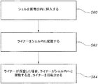
ここで図8を参照して、本発明の一実施形態の使用方法を記載する。工程s60において、シェル16を寛骨臼(図示せず)内に挿入する。ライナー10、50をシェル内に配置する(s62)。ライナー10、50が浮遊している場合、ユーザーは、シェル16が図6に示すようにシェル16内へと摺動する迄、ライナー10、50を回転させる(工程s64)。いくつかの実施形態において、工程s60は、ライナー10、50をシェル内に挿入した後に行ってもよい。換言すれば、ライナー/シェルの組み合わせは、手術室内で組立てられてもよく、又は事前に組立てられたライナー及びシェルを有する一体鋳造のシェルのように、予め組立てられて入手されてもよい。ユーザーは、手術中にシェルとライナーとを組立てる外科医であってもよく、又は装置を予め組立てた後、シェル及びライナーの組立体を予め組立てられた状態で外科医に供給する者であってもよい。
Here, a method of using one embodiment of the present invention will be described with reference to FIG. In step s60, the
ここで図9を参照すると、ライナー10の部分断面図が示されている。本実施形態では、ライナー10は、ロック部分20、複合曲線状部分22及びドーム部分24を含む外側表面14を有する。複合曲線状部分22は、放射状部分25及び接線部分26の2つの部分を含む。図9は、様々な寸法を有するこれらの部分及び領域を明記する一実施形態を示す。図示するように、ロック部分20は、約0.635〜0.762cm(0.250〜0.300インチ)の高さ70を有する。ロック部分20は、約3.05cm(1.2インチ)〜5.08cm(2.0インチ)のテーパゲージ径72と、約0.483cm(0.190インチ)〜5.59cm(2.20インチ)のテーパゲージ位置74とを有する。ロック部分20は、5〜6度のテーパ角度76も有する。
Here, referring to FIG. 9, a partial cross-sectional view of the
放射状部分25は、0.635〜1.91cm(0.250〜0.750インチ)の混合半径78を有する。接線平坦部分は、約9.0〜10.0度の角度80の間を延び、約0.254〜0.381cm(0.10〜0.15インチ)の長さ82を有する。
The
本発明には様々な改変及び代替的形態が考えられるが、その特定の実施形態を図面に例として示し、本明細書に詳細に記載する。ただし、本発明を開示される特定の形態に限定することを何ら意図するものではなく、その逆に、添付の特許請求の範囲において定義される発明の趣旨並びに範囲に包含される全ての改変物、均等物及び代替物を網羅することを意図するものであることが理解されるべきである。 Various modifications and alternative forms of the present invention are conceivable, the particular embodiments of which are illustrated in the drawings as examples and are described in detail herein. However, it is not intended to limit the present invention to the specific form disclosed, and conversely, all modifications included in the purpose and scope of the invention defined in the appended claims. It should be understood that it is intended to cover equivalents and alternatives.
〔実施の態様〕
(1) 股関節形成術に使用される寛骨臼シェル内に挿入されるように適合されたライナーであって、
大腿骨頭に係合するように適合された凹状の内側表面と、
前記寛骨臼シェルに係合するように適合された外側表面と、
前記内側表面と前記外側表面との間に延びる縁部であって、前記外側表面が、前記縁部から延びるロック部分と、第1の推移地点において前記ロック部分から延びる複合曲線状部分と、前記複合曲線状部分から延びるドーム部分と、を含み、前記第1の推移地点において、前記複合曲線状部分が前記ロック部分に対して接線をなす、縁部と、を含むライナー。
(2) 前記複合曲線状部分が、放射状部分及び接線部分を含む、実施態様1に記載のライナー。
(3) 前記放射状部分が、前記第1の推移地点において前記ロック部分から延びる、実施態様2に記載のライナー。
(4) 前記接線部分が直線である、実施態様2に記載のライナー。
(5) 前記接線部分が、第2の推移地点において前記放射状部分から延びる、実施態様4に記載のライナー。
(6) 前記接線部分が、前記第2の推移地点において前記放射状部分に対して接線をなす、実施態様5に記載のライナー。
(7) 前記ドーム部分が、第3の推移地点において前記接線部分から延びる、実施態様2に記載のライナー。
(8) 前記接線部分が、前記第3の推移地点において前記ドーム部分に対して接線をなす、実施態様7に記載のライナー。
(9) 前記ドーム部分が、推移地点において前記複合曲線状部分から延び、前記複合曲線状部分が、前記推移地点において前記ドーム部分に対して接線をなす、実施態様1に記載のライナー。
(10) 関節形成術に使用されるキットであって、
シェルと、
前記シェル内に挿入されるように適合されたライナーであって、内側表面及び外側表面を含み、前記内側表面が略凹状であり、前記外側表面が寛骨臼シェルに係合するように適合され、前記外側表面がロック部分及び複合曲線状部分を含み、前記複合曲線状部分が、放射状部分及び直線接線部分を含む、ライナーと、を備えるキット。
[Implementation]
(1) A liner adapted to be inserted into the acetabular shell used in hip arthroplasty.
With a concave medial surface adapted to engage the femoral head,
With an outer surface adapted to engage the acetabular shell,
An edge portion extending between the inner surface and the outer surface, wherein the outer surface has a lock portion extending from the edge portion, a composite curved portion extending from the lock portion at a first transition point, and the above-mentioned. A liner comprising a dome portion extending from the composite curved portion and an edge portion at which the composite curved portion is tangent to the lock portion at the first transition point.
(2) The liner according to the first embodiment, wherein the composite curved portion includes a radial portion and a tangential portion.
(3) The liner according to the second embodiment, wherein the radial portion extends from the lock portion at the first transition point.
(4) The liner according to the second embodiment, wherein the tangent portion is a straight line.
(5) The liner according to embodiment 4, wherein the tangent portion extends from the radial portion at a second transition point.
(6) The liner according to the fifth embodiment, wherein the tangent portion forms a tangent line to the radial portion at the second transition point.
(7) The liner according to the second embodiment, wherein the dome portion extends from the tangential portion at a third transition point.
(8) The liner according to the seventh embodiment, wherein the tangent portion forms a tangent line to the dome portion at the third transition point.
(9) The liner according to the first embodiment, wherein the dome portion extends from the composite curved portion at the transition point, and the composite curved portion forms a tangent to the dome portion at the transition point.
(10) A kit used for arthroplasty.
With the shell
A liner adapted to be inserted into the shell, including an inner surface and an outer surface, the inner surface being substantially concave, and the outer surface being adapted to engage the acetabular shell. A kit comprising a liner, wherein the outer surface comprises a lock portion and a composite curved portion, and the composite curved portion includes a radial portion and a straight tangential portion.
(11) 前記シェルが、前記ライナーの前記ロック部分に係合するように適合されたロック部分を含む、実施態様10に記載のキット。
(12) 前記シェルのロック部分及び前記ライナーのロック部分が自己ロックテーパである、実施態様11に記載のキット。
(13) 前記複合曲線状部分が、前記ロック部分から接線方向に延びる、実施態様10に記載のキット。
(14) 前記ライナーが、前記複合曲線状部分から接線方向に延びるドーム部分を更に含む、実施態様10に記載のキット。
(15) 前記ドーム部分が、平坦な頂部部分を含む、実施態様14に記載のキット。
(16) 関節形成術に使用されるライナーであって、前記ライナーが内側表面及び外側表面を含み、前記内側表面が略凹状であり、前記外側表面が寛骨臼シェルに係合するように適合され、前記外側表面が、ロック部分及び複合曲線状部分を含み、前記複合曲線状部分が、前記ロック部分から接線方向に延びる、ライナー。
(17) 前記外側表面が、前記複合曲線状部分から接線方向に延びるドーム部分を更に含む、実施態様16に記載のライナー。
(18) 前記複合曲線状部分が放射状部分を含み、前記ドーム部分が、前記放射状部分から接線方向に延びる、実施態様17に記載のライナー。
(19) 前記複合曲線状部分が、半径を有する放射状部分と、接線部分とを含む、実施態様16に記載のライナー。
(20) 前記接線部分が、0.254〜0.381cm(0.10〜0.15インチ)の長さを有する、実施態様19に記載のライナー。
(11) The kit of
(12) The kit according to the eleventh embodiment, wherein the lock portion of the shell and the lock portion of the liner have a self-lock taper.
(13) The kit according to the tenth embodiment, wherein the composite curved portion extends tangentially from the lock portion.
(14) The kit according to
(15) The kit according to
(16) A liner used in arthroplasty, the liner including the medial and lateral surfaces, the medial surface being substantially concave and fitted such that the lateral surface engages the acetabular shell. A liner in which the outer surface includes a lock portion and a composite curved portion, and the composite curved portion extends tangentially from the lock portion.
(17) The liner according to
(18) The liner according to embodiment 17, wherein the composite curved portion includes a radial portion, and the dome portion extends tangentially from the radial portion.
(19) The liner according to
(20) The liner according to embodiment 19, wherein the tangent portion has a length of 0.254 to 0.381 cm (0.10 to 0.15 inch).
(21) 前記ロック部分が、テーパであり、約0.635〜0.762cm(0.250〜0.300インチ)のテーパ高さを有する、実施態様16に記載のライナー。
(22) 前記内側表面と外側表面との間の縁部を更に含む、実施態様16に記載のライナー。
(21) The liner according to
(22) The liner according to
Claims (2)
大腿骨頭と係合するように適合された凹状の内側支持表面;
寛骨臼シェルに係合するように適合された外側支持表面;および
前記内側支持表面と前記外側支持表面との間に延在する縁部であって、前記外側支持表面が、前記縁部から延在するロック部分と、前記ライナーの中心線を通る断面における第1の推移地点で前記ロック部分からに延在する複合曲面状部分と、前記複合曲面状部分から延在するドーム部分とを含み、
前記第1の推移地点において、前記複合曲面状部分が前記ロック部分に対して接線方向であり、
前記複合曲面状部分は、湾曲した放射状部分と、直線状の接線部分とを含み、前記放射状部分は、前記第1の推移地点において前記ロック部分から延び、前記接線部分は、前記ライナーの中心線を通る断面における第2の推移地点において前記放射状部分から延び、
前記接線部分は、前記第2の推移地点において前記放射状部分に対して接線方向であり、
前記ドーム部分は、前記ライナーの中心線を通る断面における第3の推移地点において前記接線部分から延び、前記接線部分は、前記第3の推移地点において前記ドーム部分に対して接線方向であり、
前記ロック部分と前記放射状部分との間には連続性があり、そして、前記接線部分と前記ドーム部分との間には連続性があることによって、前記ライナーの外面全体に縁部、角部又は尖端部が存在せず、
前記ライナーの中心線を通る断面は、前記ライナーの中心部分を通る中心線すべてを含む断面である、ライナー。 A liner adapted to be inserted into the acetabular shell for use in hip arthroplasty, the liner.
Concave medial support surface adapted to engage the femoral head;
An outer support surface adapted to engage the acetabular shell; and an edge extending between the inner support surface and the outer support surface, wherein the outer support surface is from the edge. Includes an extending lock portion, a composite curved surface portion extending from the lock portion at the first transition point in the cross section passing through the center line of the liner, and a dome portion extending from the composite curved surface portion. ,
At the first transition point, the composite curved surface portion is tangential to the lock portion.
The composite curved surface portion includes a curved radial portion and a linear tangential portion, the radial portion extends from the lock portion at the first transition point, and the tangent portion is the center line of the liner. Extending from the radial portion at the second transition point in the cross section passing through
The tangential portion is tangential to the radial portion at the second transition point.
The dome portion extends from the tangential portion at a third transition point in a cross section passing through the centerline of the liner, and the tangent portion is tangential to the dome portion at the third transition point.
There is continuity between the lock portion and the radial portion, and there is continuity between the tangent portion and the dome portion, so that the entire outer surface of the liner has edges, corners or There is no tip ,
The cross section passing through the center line of the liner is a cross section including the entire center line passing through the center portion of the liner.
Applications Claiming Priority (2)
| Application Number | Priority Date | Filing Date | Title |
|---|---|---|---|
| US201161541135P | 2011-09-30 | 2011-09-30 | |
| US61/541,135 | 2011-09-30 |
Related Parent Applications (1)
| Application Number | Title | Priority Date | Filing Date |
|---|---|---|---|
| JP2018125920A Division JP6640286B2 (en) | 2011-09-30 | 2018-07-02 | Kit used for hip arthroplasty |
Publications (2)
| Publication Number | Publication Date |
|---|---|
| JP2020044411A JP2020044411A (en) | 2020-03-26 |
| JP6830995B2 true JP6830995B2 (en) | 2021-02-17 |
Family
ID=48015517
Family Applications (4)
| Application Number | Title | Priority Date | Filing Date |
|---|---|---|---|
| JP2012216146A Active JP6095928B2 (en) | 2011-09-30 | 2012-09-28 | Self-centering non-stick acetabular liner |
| JP2017025750A Active JP6367396B2 (en) | 2011-09-30 | 2017-02-15 | Self-centering non-stick acetabular liner |
| JP2018125920A Active JP6640286B2 (en) | 2011-09-30 | 2018-07-02 | Kit used for hip arthroplasty |
| JP2019232571A Active JP6830995B2 (en) | 2011-09-30 | 2019-12-24 | liner |
Family Applications Before (3)
| Application Number | Title | Priority Date | Filing Date |
|---|---|---|---|
| JP2012216146A Active JP6095928B2 (en) | 2011-09-30 | 2012-09-28 | Self-centering non-stick acetabular liner |
| JP2017025750A Active JP6367396B2 (en) | 2011-09-30 | 2017-02-15 | Self-centering non-stick acetabular liner |
| JP2018125920A Active JP6640286B2 (en) | 2011-09-30 | 2018-07-02 | Kit used for hip arthroplasty |
Country Status (4)
| Country | Link |
|---|---|
| JP (4) | JP6095928B2 (en) |
| CN (2) | CN106037995B (en) |
| AU (1) | AU2012227336B2 (en) |
| ZA (1) | ZA201207261B (en) |
Families Citing this family (1)
| Publication number | Priority date | Publication date | Assignee | Title |
|---|---|---|---|---|
| CN110495974B (en) * | 2019-09-30 | 2025-06-27 | 优适医疗科技(苏州)有限公司 | New dual-motion hip prosthesis |
Family Cites Families (17)
| Publication number | Priority date | Publication date | Assignee | Title |
|---|---|---|---|---|
| ES8704076A1 (en) * | 1984-10-17 | 1987-04-01 | Sostegni Giuliano | Hip prosthesis with a member for damping mechanical stresses. |
| ES2184017T3 (en) * | 1996-08-24 | 2003-04-01 | Cerasiv Gmbh | ARTICULATION PROTESIS. |
| DE19701536A1 (en) * | 1996-08-24 | 1998-02-26 | Cerasiv Gmbh | Joint prosthesis |
| AUPQ070399A0 (en) * | 1999-06-02 | 1999-06-24 | Cryptych Pty Ltd | Acetabular component of total hip replacement assembly |
| WO2000074604A1 (en) * | 1999-06-02 | 2000-12-14 | Australian Surgical Design And Manufacture Pty Limited | Acetabular component of total hip replacement assembly |
| AU783205C (en) * | 2000-03-15 | 2006-08-17 | Depuy Orthopaedics, Inc. | Prosthetic cup assembly which includes components possessing self-locking taper |
| US7326253B2 (en) * | 2001-11-16 | 2008-02-05 | Depuy Products, Inc. | Prosthetic cup assembly having increased assembly congruency |
| US7115145B2 (en) * | 2003-07-03 | 2006-10-03 | Zimmer, Inc. | Acetabular component |
| DE10360390B4 (en) * | 2003-12-22 | 2006-03-23 | Martin Imhof | Joint socket for a hip endoprosthesis |
| US20060048461A1 (en) * | 2004-09-06 | 2006-03-09 | Jones Dennis A | Connectors for roofs |
| FR2877563B1 (en) * | 2004-11-08 | 2007-11-30 | Centre Nat Rech Scient Cnrse | ACETABULAR PROSTHESIS FOR FIXING WITHOUT CEMENT |
| DE102005025686B4 (en) * | 2005-06-03 | 2007-10-11 | Mathys Ag Bettlach | Hip endoprosthesis |
| DE102006001430A1 (en) * | 2006-01-10 | 2007-07-12 | Siebel, Thomas, Dr. | Implant for forming an acetabular cup |
| EP2007318B8 (en) * | 2006-03-20 | 2014-03-12 | Smith & Nephew, Inc. | Acetabular cup assembly for multiple bearing materials |
| US20070239283A1 (en) * | 2006-04-11 | 2007-10-11 | Berger Richard A | Acetabular cup conversion ring |
| WO2008058756A2 (en) * | 2006-11-17 | 2008-05-22 | Scyon Orthopaedics Ag | Wear-reducing geometry of articulations in total joint replacements |
| CA2712559C (en) * | 2008-01-30 | 2015-03-31 | Zimmer, Inc. | Orthopedic component of low stiffness |
-
2012
- 2012-09-26 AU AU2012227336A patent/AU2012227336B2/en active Active
- 2012-09-27 ZA ZA2012/07261A patent/ZA201207261B/en unknown
- 2012-09-28 CN CN201610537083.7A patent/CN106037995B/en active Active
- 2012-09-28 JP JP2012216146A patent/JP6095928B2/en active Active
- 2012-09-28 CN CN201210370730.1A patent/CN103027766B/en active Active
-
2017
- 2017-02-15 JP JP2017025750A patent/JP6367396B2/en active Active
-
2018
- 2018-07-02 JP JP2018125920A patent/JP6640286B2/en active Active
-
2019
- 2019-12-24 JP JP2019232571A patent/JP6830995B2/en active Active
Also Published As
| Publication number | Publication date |
|---|---|
| CN103027766A (en) | 2013-04-10 |
| JP2013078583A (en) | 2013-05-02 |
| ZA201207261B (en) | 2014-09-25 |
| JP6640286B2 (en) | 2020-02-05 |
| JP6367396B2 (en) | 2018-08-01 |
| AU2012227336A1 (en) | 2013-04-18 |
| CN103027766B (en) | 2016-08-17 |
| CN106037995B (en) | 2018-03-30 |
| JP6095928B2 (en) | 2017-03-15 |
| CN106037995A (en) | 2016-10-26 |
| JP2017080600A (en) | 2017-05-18 |
| JP2018143863A (en) | 2018-09-20 |
| JP2020044411A (en) | 2020-03-26 |
| AU2012227336B2 (en) | 2015-03-26 |
Similar Documents
| Publication | Publication Date | Title |
|---|---|---|
| EP2574310B1 (en) | Self-centering, anti-seizing acetabular liner | |
| JP6109515B2 (en) | Acetabular cup with bending resistance | |
| AU2005202696B2 (en) | Extended radius prosthesis and associated method | |
| JP6830995B2 (en) | liner | |
| WO2018063872A1 (en) | Acetabular shell and liner system | |
| AU2017203409B2 (en) | Self-centering, anti-seizing acetabular liner |
Legal Events
| Date | Code | Title | Description |
|---|---|---|---|
| A521 | Request for written amendment filed |
Free format text: JAPANESE INTERMEDIATE CODE: A523 Effective date: 20200121 |
|
| A621 | Written request for application examination |
Free format text: JAPANESE INTERMEDIATE CODE: A621 Effective date: 20200121 |
|
| A977 | Report on retrieval |
Free format text: JAPANESE INTERMEDIATE CODE: A971007 Effective date: 20201225 |
|
| TRDD | Decision of grant or rejection written | ||
| A01 | Written decision to grant a patent or to grant a registration (utility model) |
Free format text: JAPANESE INTERMEDIATE CODE: A01 Effective date: 20210112 |
|
| A61 | First payment of annual fees (during grant procedure) |
Free format text: JAPANESE INTERMEDIATE CODE: A61 Effective date: 20210127 |
|
| R150 | Certificate of patent or registration of utility model |
Ref document number: 6830995 Country of ref document: JP Free format text: JAPANESE INTERMEDIATE CODE: R150 |
|
| R250 | Receipt of annual fees |
Free format text: JAPANESE INTERMEDIATE CODE: R250 |
|
| R250 | Receipt of annual fees |
Free format text: JAPANESE INTERMEDIATE CODE: R250 |
|
| R250 | Receipt of annual fees |
Free format text: JAPANESE INTERMEDIATE CODE: R250 |