JP6832142B2 - Phenol resin foam plate and its manufacturing method - Google Patents
Phenol resin foam plate and its manufacturing method Download PDFInfo
- Publication number
- JP6832142B2 JP6832142B2 JP2016239939A JP2016239939A JP6832142B2 JP 6832142 B2 JP6832142 B2 JP 6832142B2 JP 2016239939 A JP2016239939 A JP 2016239939A JP 2016239939 A JP2016239939 A JP 2016239939A JP 6832142 B2 JP6832142 B2 JP 6832142B2
- Authority
- JP
- Japan
- Prior art keywords
- face material
- phenol resin
- resin foam
- foam plate
- mass
- Prior art date
- Legal status (The legal status is an assumption and is not a legal conclusion. Google has not performed a legal analysis and makes no representation as to the accuracy of the status listed.)
- Active
Links
Images


Landscapes
- Casting Or Compression Moulding Of Plastics Or The Like (AREA)
- Molding Of Porous Articles (AREA)
- Laminated Bodies (AREA)
Description
本発明は、フェノール樹脂発泡板及びその製造方法に関する。 The present invention relates to a phenolic resin foam plate and a method for producing the same.
家屋等の断熱材として、断熱パネルが汎用される。断熱パネルとしては、フェノール樹脂の発泡層と、この発泡層の片面又は両面に設けられた面材とを備えるフェノール樹脂発泡板が知られている。
フェノール樹脂の発泡層は、物理的衝撃に対して、比較的脆い。このため、フェノール樹脂の発泡層の片面又は両面に面材を設けることで、フェノール樹脂の発泡層の保護を図っている。
Insulation panels are widely used as heat insulating materials for houses and the like. As the heat insulating panel, a phenol resin foam plate including a foam layer of phenol resin and face materials provided on one side or both sides of the foam layer is known.
The foamed layer of phenolic resin is relatively brittle to physical impact. For this reason, the foamed layer of the phenol resin is protected by providing face materials on one side or both sides of the foamed layer of the phenol resin.
ハロゲン原子を含まない炭化水素は、オゾン層破壊係数がゼロで温暖化係数も小さい発泡剤であるが、ハロゲン化炭化水素を発泡剤とした場合に比べて、フェノール樹脂発泡体の断熱性能や機械的強度が劣る。
特許文献1には、炭化水素発泡剤を用いてフェノール樹脂発泡体を製造する方法が記載されている。
特許文献2には、オゾン層破壊係数がゼロで温暖化係数も小さく、炭化水素発泡剤よりも熱伝導率を低下させやすい発泡剤として、ハロゲン化不飽和炭化水素を用いることが提案されている。
Hydrocarbons that do not contain halogen atoms are foaming agents that have a zero ozone depletion potential and a small global warming potential, but compared to the case where halogenated hydrocarbons are used as foaming agents, the heat insulating performance and machinery of phenol resin foams Inferior target strength.
Patent Document 1 describes a method for producing a phenol resin foam using a hydrocarbon foaming agent.
Patent Document 2 proposes the use of halogenated unsaturated hydrocarbons as a foaming agent having a zero ozone depletion potential, a small global warming potential, and a lower thermal conductivity than a hydrocarbon foaming agent. ..
しかしながら、炭化水素系発泡剤とハロゲン化不飽和炭化水素発泡剤とは反応性が異なり発泡状態が異なるため、炭化水素系発泡剤を用いたフェノール樹脂発泡体において好適な条件を、ハロゲン化不飽和炭化水素発泡剤を用いたフェノール樹脂発泡体に適用できるかどうかは予測できない。
本発明者らの知見によれば、走行する面材上で連続的に発泡させてフェノール樹脂発泡板を製造する方法において、炭化水素系発泡剤の代わりにハロゲン化不飽和炭化水素発泡剤を用いると、発泡板の撓み易さが変化し、施工後に変形が生じるおそれがある。
また家屋等の建材として用いられる発泡板には難燃性が求められる。
本発明は、発泡剤がハロゲン化不飽和炭化水素を含み、難燃性に優れ、施工後に変形が生じ難いフェノール樹脂発泡板およびその製造方法の提供を目的とする。
However, since the hydrocarbon-based foaming agent and the halogenated unsaturated hydrocarbon foaming agent have different reactivity and different foaming states, the conditions suitable for the phenol resin foam using the hydrocarbon-based foaming agent are the halogenated unsaturated. It is unpredictable whether it can be applied to phenolic resin foams using hydrocarbon foaming agents.
According to the findings of the present inventors, a halogenated unsaturated hydrocarbon foaming agent is used instead of the hydrocarbon-based foaming agent in a method for producing a phenol resin foaming plate by continuously foaming on a traveling face material. As a result, the flexibility of the foam plate changes, and there is a risk of deformation after construction.
In addition, foam boards used as building materials for houses and the like are required to have flame retardancy.
An object of the present invention is to provide a phenol formaldehyde foam plate containing a halogenated unsaturated hydrocarbon, excellent flame retardancy, and less likely to be deformed after construction, and a method for producing the same.
本発明は以下の態様を有する。
[1]フェノール樹脂とハロゲン化不飽和炭化水素を含み、密度が15〜50kg/m3、独立気泡率が80〜99%、制限酸素指数が28容量%以上である発泡層と、前記発泡層の両面に接着剤層を介することなく積層された、ガラス繊維を含む面材とが備えられた、平面視長方形のフェノール樹脂発泡板であって、長さ方向における曲げ弾性率Exと、幅方向における曲げ弾性率Eyとは、下記(1)式を満たす、フェノール樹脂発泡板。
1.1≦Ex/Ey≦2.5・・・(1)
[2]EN1604に準じて測定される70℃における、前記フェノール樹脂発泡板の寸法変化量D1と、前記発泡層のみの寸法変化量D10とは、下記(2)式を満たす、[1]に記載のフェノール樹脂発泡板。
0.18≦D1/D10≦0.9・・・(2)
[3]前記面材に対するガラス繊維の含有量が10質量%以上である、[1]又は[2]に記載のフェノール樹脂発泡板。
[4]前記面材の目付が30g/m2以上である、[1]〜[3]のいずれかに記載のフェノール樹脂発泡板。
[5]前記[1]〜[4]のいずれかに記載のフェノール樹脂発泡板の製造方法であって、任意の速度で走行する第一の面材上に、フェノール樹脂と発泡剤と架橋剤とを含有する発泡性樹脂組成物を吐出する第一の工程と、
前記第一の面材上に吐出された前記発泡性樹脂組成物上に第二の面材を載置し、加熱して、発泡し硬化する第二の工程と、を有する、フェノール樹脂発泡板の製造方法。
[6]前記第一の工程は、TD方向に並ぶ2以上のノズルから前記発泡性樹脂組成物を前記第一の面材上に吐出し、前記ノズルの軸線と、前記第一の面材とのなす角度は、60°以上90°未満である、[5]に記載のフェノール樹脂発泡板の製造方法。
The present invention has the following aspects.
[1] A foamed layer containing a phenol resin and an unsaturated hydrocarbon halogenated, having a density of 15 to 50 kg / m 3 , a closed cell ratio of 80 to 99%, and an oxygen limiting index of 28% by volume or more, and the foamed layer. It is a phenol resin foam plate having a rectangular shape in a plan view and provided with a face material containing glass fibers laminated on both sides of the above without using an adhesive layer, and has a bending elasticity Ex in the length direction and a bending elasticity Ex in the width direction. The bending elasticity Eye in the above is a phenol resin foam plate satisfying the following equation (1).
1.1 ≤ Ex / Ey ≤ 2.5 ... (1)
[2] at 70 ° C. as measured in accordance with EN1604, the dimensional change D 1 of the said phenolic resin foam plate, said the amount of dimensional change D 10 of only the foam layer, satisfies the following equation (2), [1 ] The phenolic resin foam plate described in.
0.18 ≤ D 1 / D 10 ≤ 0.9 ... (2)
[3] The phenolic resin foam plate according to [1] or [2], wherein the content of the glass fiber with respect to the face material is 10% by mass or more.
[4] The phenolic resin foam plate according to any one of [1] to [3], wherein the face material has a basis weight of 30 g / m 2 or more.
[5] The method for producing a phenol resin foam plate according to any one of the above [1] to [4], wherein the phenol resin, the foaming agent, and the cross-linking agent are placed on the first face material traveling at an arbitrary speed. The first step of discharging the foaming resin composition containing
A phenolic resin foam plate comprising a second step of placing a second face material on the foamable resin composition discharged onto the first face material, heating the material, and foaming and curing the second face material. Manufacturing method.
[6] In the first step, the foamable resin composition is discharged onto the first face material from two or more nozzles arranged in the TD direction, and the axis of the nozzle and the first face material are used. The method for producing a phenol resin foam plate according to [5], wherein the angle formed by the nozzle is 60 ° or more and less than 90 °.
本発明によれば、発泡剤がハロゲン化不飽和炭化水素を含み、難燃性に優れ、施工後に変形が生じ難いフェノール樹脂発泡板が得られる。 According to the present invention, it is possible to obtain a phenol resin foam plate in which the foaming agent contains halogenated unsaturated hydrocarbons, has excellent flame retardancy, and is less likely to be deformed after construction.
本発明のフェノール樹脂発泡板は、フェノール樹脂の発泡層(以下、単に発泡層ということがある。)と、発泡層の両面に設けられた面材とを備える。面材は発泡層に接着剤層を介することなく積層されている。
以下、図面を参照して、フェノール樹脂発泡板について説明する。
The phenol resin foam plate of the present invention includes a foam layer of phenol resin (hereinafter, may be simply referred to as a foam layer) and face materials provided on both sides of the foam layer. The face material is laminated on the foam layer without an adhesive layer.
Hereinafter, the phenol resin foam plate will be described with reference to the drawings.
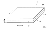
図1のフェノール樹脂発泡板1は、平板状の発泡層10と第一の面材12と第二の面材14とを備える。第一の面材12は、発泡層10の一方の面に設けられている。第二の面材14は、発泡層10の他方の面に設けられている。
フェノール樹脂発泡板1は、X方向を長さ方向、Y方向を幅方向とする、平面視長方形である。本実施形態において、X方向はMD(Machine Direction)方向、Y方向はTD(Transverse Direction)方向である。
The phenolic resin foam plate 1 of FIG. 1 includes a
The phenol resin foam plate 1 is a rectangular shape in a plan view with the X direction as the length direction and the Y direction as the width direction. In the present embodiment, the X direction is the MD (Machine Direction) direction, and the Y direction is the TD (Transverse Direction) direction.
発泡層10は、発泡性樹脂組成物を発泡し硬化してなる発泡体である。発泡性樹脂組成物は、フェノール樹脂と発泡剤とを含む。
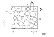
図2に示すように、発泡層10には、2以上の気泡20が形成されている。気泡20の内、少なくとも一部は独立気泡である。なお、図2は、図1のフェノール樹脂発泡板1を仮想線Pで厚さ方向に二等分し、その断面を平面視で観察した際の部分断面図である。図2において、RMは気泡20のMD方向の長さを表し、RTは気泡20のTD方向の長さを表す。RM/RTは気泡アスペクト比を表す。
The
As shown in FIG. 2, two or
フェノール樹脂としては、レゾール型のものが好ましい。
レゾール型フェノール樹脂は、フェノール化合物とアルデヒドとをアルカリ触媒の存在下で反応させて得られるフェノール樹脂である。
フェノール化合物としては、フェノール、クレゾール、キシレノール、パラアルキルフェノール、パラフェニルフェノール、レゾルシノール及びこれらの変性物等が挙げられる。
アルデヒドとしては、ホルムアルデヒド、パラホルムアルデヒド、フルフラール、アセトアルデヒド等が挙げられる。アルカリ触媒としては、水酸化ナトリウム、水酸化カリウム、水酸化カルシウム、脂肪族アミン(トリメチルアミン、トリエチルアミン等)等が挙げられる。
ただしフェノール化合物、アルデヒド、アルカリ触媒はそれぞれ上記のものに限定されるものではない。フェノール樹脂は、1種単独で用いられてもよいし、2種以上が組み合されて用いられてもよい。
フェノール化合物とアルデヒドとの使用割合は特に限定されない。好ましくは、フェノール化合物:アルデヒドのモル比で、1:1〜1:3であり、より好ましくは1:1.3〜1:2.5である。
As the phenol resin, a resole type is preferable.
The resol type phenol resin is a phenol resin obtained by reacting a phenol compound and an aldehyde in the presence of an alkaline catalyst.
Examples of the phenol compound include phenol, cresol, xylenol, paraalkylphenol, paraphenylphenol, resorcinol and modified products thereof.
Examples of the aldehyde include formaldehyde, paraformaldehyde, furfural, acetaldehyde and the like. Examples of the alkaline catalyst include sodium hydroxide, potassium hydroxide, calcium hydroxide, aliphatic amines (trimethylamine, triethylamine, etc.) and the like.
However, the phenol compound, the aldehyde, and the alkali catalyst are not limited to the above. One type of phenol resin may be used alone, or two or more types may be used in combination.
The ratio of the phenol compound and the aldehyde is not particularly limited. The molar ratio of phenolic compound: aldehyde is preferably 1: 1 to 1: 3, and more preferably 1: 1.3 to 1: 2.5.
フェノール樹脂の重量平均分子量Mwは、400〜3000が好ましく、700〜2000がより好ましい。重量平均分子量が上記下限値以上であれば、独立気泡率が高まり、圧縮強度のさらなる向上及び熱伝導率のさらなる向上を図りやすい。また、ボイドの形成を防止しやすい。重量平均分子量Mwが上記上限値以下であれば発泡性樹脂組成物の粘度が高まりすぎず、所望する発泡倍率を得やすい。 The weight average molecular weight Mw of the phenol resin is preferably 400 to 3000, more preferably 700 to 2000. When the weight average molecular weight is at least the above lower limit value, the closed cell ratio is increased, and it is easy to further improve the compressive strength and the thermal conductivity. In addition, it is easy to prevent the formation of voids. When the weight average molecular weight Mw is not more than the above upper limit value, the viscosity of the foamable resin composition does not increase too much, and it is easy to obtain a desired expansion ratio.
発泡剤は、ハロゲン化不飽和炭化水素を含む。ハロゲン化不飽和炭化水素は、発泡層10の難燃性をより高め、断熱性を高める観点から好ましい。
ハロゲン化不飽和炭化水素としては、フッ素化不飽和炭化水素、塩素化不飽和炭化水素、塩素化フッ素化不飽和炭化水素、臭素化フッ素化不飽和炭化水素、ヨウ素化フッ素化不飽和炭化水素等が挙げられる。ハロゲン化不飽和炭化水素は、水素原子の全てがハロゲン原子で置換されたものでもよいし、水素原子の一部がハロゲン原子で置換されたものでもよい。
これらのハロゲン化不飽和炭化水素は、1種単独で用いられてもよいし、2種以上が組み合わされて用いられてもよい。
ハロゲン化不飽和炭化水素は、オゾン破壊係数(ODP)および地球温暖化係数(GWP)が小さく、環境に与える影響が小さい点で有利である。ハロゲン化不飽和炭化水素としては、塩素化フッ素化不飽和炭化水素またはフッ素化不飽和炭化水素が好ましい。
The foaming agent contains a halogenated unsaturated hydrocarbon. Halogenated unsaturated hydrocarbons are preferable from the viewpoint of further enhancing the flame retardancy of the
Examples of halogenated unsaturated hydrocarbons include fluorinated unsaturated hydrocarbons, chlorinated unsaturated hydrocarbons, chlorinated fluorinated unsaturated hydrocarbons, brominated fluorinated unsaturated hydrocarbons, and iodide fluorinated unsaturated hydrocarbons. Can be mentioned. The halogenated unsaturated hydrocarbon may have all hydrogen atoms substituted with halogen atoms, or may have some hydrogen atoms substituted with halogen atoms.
These halogenated unsaturated hydrocarbons may be used alone or in combination of two or more.
Halogenated unsaturated hydrocarbons are advantageous in that they have a small ozone depletion potential (ODP) and a global warming potential (GWP) and have a small impact on the environment. As the halogenated unsaturated hydrocarbon, a chlorinated fluorinated unsaturated hydrocarbon or a fluorinated unsaturated hydrocarbon is preferable.
塩素化フッ素化不飽和炭化水素としては、分子内に塩素原子とフッ素原子と二重結合を含むものが挙げられ、例えば、1,2−ジクロロ−1,2−ジフルオロエテン(E及びZ異性体)、1−クロロ−3,3,3−トリフルオロプロペン(HCFO−1233zd)(E及びZ異性体)(例えば、HoneyWell社製、商品名:SOLSTICE LBA)、1−クロロ−2,3,3−トリフルオロプロペン(HCFO−1233yd)(E及びZ異性体)、1−クロロ−1,3,3−トリフルオロプロペン(HCFO−1233zb)(E及びZ異性体)、2−クロロ−1,3,3−トリフルオロプロペン(HCFO−1233xe)(E及びZ異性体)、2−クロロ−2,2,3−トリフルオロプロペン(HCFO−1233xc)、2−クロロ−3,3,3−トリフルオロプロペン(HCFO−1233xf)(例えば、SynQuest Laboratories社製、製品番号:1300−7−09)、3−クロロ−1,2,3−トリフルオロプロペン(HCFO−1233ye)(E及びZ異性体)、3−クロロ−1,1,2−トリフルオロプロペン(HCFO−1233yc)、3,3−ジクロロ−3−フルオロプロペン、1,2−ジクロロ−3,3,3−トリフルオロプロペン(HFO−1223xd)(E及びZ異性体)、2−クロロ−1,1,1,4,4,4−ヘキサフルオロ−2−ブテン(E及びZ異性体)、及び2−クロロ−1,1,1,3,4,4,4−ヘプタフルオロ−2−ブテン(E及びZ異体)等が挙げられる。 Examples of the chlorinated fluorinated unsaturated hydrocarbon include those containing a chlorine atom, a fluorine atom and a double bond in the molecule, and examples thereof include 1,2-dichloro-1,2-difluoroethane (E and Z isomers). ), 1-Chloro-3,3,3-trifluoropropene (HCFO-1233zd) (E and Z isomers) (for example, manufactured by HoneyWell, trade name: SOLSTICE LBA), 1-chloro-2,3,3 -Trifluoropropene (HCFO-1233yd) (E and Z isomers), 1-chloro-1,3,3-trifluoropropene (HCFO-1233zb) (E and Z isomers), 2-chloro-1,3 , 3-Trifluoropropene (HCFO-1233xe) (E and Z isomers), 2-chloro-2,2,3-trifluoropropene (HCFO-1233xc), 2-chloro-3,3,3-trifluoro Propen (HCFO-1233xf) (eg, manufactured by SynQuest Laboratories, product number: 1300-7-09), 3-chloro-1,2,3-trifluoropropene (HCFO-1233ye) (E and Z isomers), 3-Chloro-1,1,2-trifluoropropene (HCFO-1233yc), 3,3-dichloro-3-fluoropropene, 1,2-dichloro-3,3,3-trifluoropropene (HFO-1223xd) (E and Z isomers), 2-chloro-1,1,1,4,4,4-hexafluoro-2-butene (E and Z isomers), and 2-chloro-1,1,1,3 , 4, 4,4-Heptafluoro-2-butene (E and Z variants) and the like.
フッ素化不飽和炭化水素としては、分子内にフッ素原子と二重結合を含むものが挙げられ、例えば、2,3,3,3−テトラフルオロプロペン(HFO−1234yf)、1,3,3,3−テトラフルオロプロペン(HFO−1234ze)(E及びZ異性体)、1,1,1,4,4,4−ヘキサフルオロ−2−ブテン(HFO1336mzz)(E及びZ異性体)(SynQuest Laboratories社製、製品番号:1300−3−Z6)等の特表2009−513812号公報等に開示されるものが挙げられる。 Examples of the fluorinated unsaturated hydrocarbon include those containing a fluorine atom and a double bond in the molecule, and examples thereof include 2,3,3,3-tetrafluoropropene (HFO-1234yf), 1,3,3. 3-Tetrafluoropropene (HFO-1234ze) (E and Z isomers), 1,1,1,4,4,4-hexafluoro-2-butene (HFO1336 mzz) (E and Z isomers) (SynQuest Laboratories) , Product number: 1300-3-Z6), etc., which are disclosed in Japanese Patent Publication No. 2009-513812.
発泡剤は、さらに飽和炭化水素またはハロゲン化飽和炭化水素を含んでもよい。
飽和炭化水素としては、発泡剤として公知のものを用いることができ、沸点が−20℃以上100℃以下のものが好適に用いられる。
飽和炭化水素としては、炭素数が4以上6以下の環状分子構造又は炭素数4以上6以下の鎖状分子構造を有するものが好ましく、例えば、イソブタン、ノルマルブタン、シクロブタン、ノルマルペンタン、イソペンタン、シクロペンタン、ネオペンタン等が挙げられる。
これらの飽和炭化水素は、1種単独で用いられてもよいし、2種以上が組み合わされて用いられてもよい。これらの飽和炭化水素は、低温域(例えば、−80℃程度の冷凍庫用断熱材)から高温域(例えば200℃程度の加熱体用断熱材)までの広い温度範囲で優れた断熱性能を確保でき、比較的安価であり経済的にも有利である。
The foaming agent may further contain saturated hydrocarbons or halogenated saturated hydrocarbons.
As the saturated hydrocarbon, a known foaming agent can be used, and one having a boiling point of −20 ° C. or higher and 100 ° C. or lower is preferably used.
The saturated hydrocarbon preferably has a cyclic molecular structure having 4 or more and 6 or less carbon atoms or a chain molecular structure having 4 or more and 6 or less carbon atoms. For example, isobutane, normal butane, cyclobutane, normal pentane, isopentane, cyclo Examples include pentane and neopentane.
These saturated hydrocarbons may be used alone or in combination of two or more. These saturated hydrocarbons can ensure excellent heat insulating performance in a wide temperature range from a low temperature range (for example, a heat insulating material for a freezer at about -80 ° C) to a high temperature range (for example, a heat insulating material for a heating body at about 200 ° C). It is relatively inexpensive and economically advantageous.
ハロゲン化飽和炭化水素としては、発泡剤として公知のものを用いることができる。例えば、塩素化飽和炭化水素、フッ素化飽和炭化水素等のハロゲン化飽和炭化水素等が挙げられる。ハロゲン化飽和炭化水素は、水素の全てがハロゲンで置換されたものでもよいし、水素の一部がハロゲンで置換されたものでもよい。
これらのハロゲン化飽和炭化水素は、1種単独で用いられてもよいし、2種以上が組み合わされて用いられてもよい。
As the halogenated saturated hydrocarbon, a known foaming agent can be used. For example, halogenated saturated hydrocarbons such as chlorinated saturated hydrocarbons and fluorinated saturated hydrocarbons can be mentioned. The halogenated saturated hydrocarbon may be one in which all of hydrogen is substituted with halogen, or one in which part of hydrogen is substituted with halogen.
These halogenated saturated hydrocarbons may be used alone or in combination of two or more.
塩素化飽和炭化水素としては、炭素数が2以上5以下であるものが好ましく、例えばジクロロエタン、プロピルクロライド、イソプロピルクロライド(2−クロロプロパン)、ブチルクロライド、イソブチルクロライド、ペンチルクロライド、イソペンチルクロライド等が挙げられる。中でも、オゾン層破壊係数が低く、環境適合性に優れる点で、イソプロピルクロライドが好ましい。 The chlorinated saturated hydrocarbon preferably has 2 or more and 5 or less carbon atoms, and examples thereof include dichloroethane, propyl chloride, isopropyl chloride (2-chloropropane), butyl chloride, isobutyl chloride, pentyl chloride, and isopentyl chloride. Be done. Among them, isopropyl chloride is preferable because it has a low ozone depletion potential and is excellent in environmental compatibility.
フッ素化飽和炭化水素としては、例えば、ジフルオロメタン(HFC32)、1,1,1,2,2−ペンタフルオロエタン(HFC125)、1,1,1−トリフルオロエタン(HFC143a)、1,1,2,2−テトラフルオロエタン(HFC134)、1,1,1,2−テトラフルオロエタン(HFC134a)、1,1−ジフルオロエタン(HFC152a)、1,1,1,2,3,3,3−ヘプタフルオロプロパン(HFC227ea)、1,1,1,3,3−ペンタフルオプロパン(HFC245fa)、1,1,1,3,3−ペンタフルオロブタン(HFC365mfc)及び1,1,1,2,2,3,4,5,5,5−デカフルオロペンタン(HFC4310mee)等のハイドロフルオロカーボンが挙げられる。 Examples of the fluorinated saturated hydrocarbon include difluoromethane (HFC32), 1,1,1,2,2-pentafluoroethane (HFC125), 1,1,1-trifluoroethane (HFC143a), 1,1,1. 2,2-Tetrafluoroethane (HFC134), 1,1,1,2-tetrafluoroethane (HFC134a), 1,1-difluoroethane (HFC152a), 1,1,1,2,3,3,3-hepta Fluoropropane (HFC227ea), 1,1,1,3,3-pentafluoropropane (HFC245fa), 1,1,1,3,3-pentafluoroethane (HFC365mfc) and 1,1,1,2,2 Hydrofluorocarbons such as 3,4,5,5,5-decafluoropentane (HFC4310mee) can be mentioned.
発泡剤は、必要に応じて、ハロゲン化不飽和炭化水素、ハロゲン化飽和炭化水素、および飽和炭化水素以外の他の発泡剤をさらに含んでもよい。他の発泡剤としては、窒素、アルゴン、炭酸ガス、空気等の低沸点ガス;炭酸水素ナトリウム、炭酸ナトリウム、炭酸カルシウム、炭酸マグネシウム、アゾジカルボン酸アミド、アゾビスイソブチロニトリル、アゾジカルボン酸バリウム、N,N’−ジニトロソペンタメチレンテトラミン、p,p’−オキシビスベンゼンスルホニルヒドラジド、トリヒドラジノトリアジン等の化学発泡剤;多孔質固体材料等が挙げられる。 The foaming agent may further contain a halogenated unsaturated hydrocarbon, a halogenated saturated hydrocarbon, and other foaming agents other than the saturated hydrocarbon, if necessary. Other foaming agents include low boiling gases such as nitrogen, argon, carbon dioxide, and air; sodium hydrogen carbonate, sodium carbonate, calcium carbonate, magnesium carbonate, azodicarboxylic acid amide, azobisisobutyronitrile, barium azodicarboxylic acid. , N, N'-dinitrosopentamethylenetetramine, p, p'-oxybisbenzenesulfonylhydrazide, trihydrazinotriazine and other chemical foaming agents; porous solid materials and the like.
発泡性樹脂組成物中の発泡剤の含有量は、フェノール樹脂100質量部に対し、1〜25量部が好ましく、3〜15質量部がより好ましく、5〜11質量部がさらに好ましい。
発泡剤の合計100質量部のうち、ハロゲン化不飽和炭化水素の割合は、10量部以上が好ましく、20質量部以上がより好ましく、30質量部以上が最も好ましい。100質量部でもよい。
The content of the foaming agent in the foamable resin composition is preferably 1 to 25 parts by mass, more preferably 3 to 15 parts by mass, and even more preferably 5 to 11 parts by mass with respect to 100 parts by mass of the phenol resin.
The proportion of the halogenated unsaturated hydrocarbon in the total 100 parts by mass of the foaming agent is preferably 10 parts by mass or more, more preferably 20 parts by mass or more, and most preferably 30 parts by mass or more. It may be 100 parts by mass.
発泡性樹脂組成物は、酸触媒を含有してもよい。酸触媒は、フェノール樹脂を硬化させるために使用される。
酸触媒としては、ベンゼンスルホン酸、エチルベンゼンスルホン酸、パラトルエンスルホン酸、キシレンスルホン酸、ナフタレンスルホン酸、フェノールスルホン酸等の有機酸、硫酸、リン酸等の無機酸等が挙げられる。これらの酸触媒は、1種を単独で用いてもよく、2種以上を組み合わせて用いてもよい。
The foamable resin composition may contain an acid catalyst. Acid catalysts are used to cure phenolic resins.
Examples of the acid catalyst include organic acids such as benzenesulfonic acid, ethylbenzenesulfonic acid, paratoluenesulfonic acid, xylenesulfonic acid, naphthalenesulfonic acid and phenolsulfonic acid, and inorganic acids such as sulfuric acid and phosphoric acid. One of these acid catalysts may be used alone, or two or more of them may be used in combination.
発泡性樹脂組成物中の酸触媒の含有量は、フェノール樹脂100質量部当り、5〜30質量部が好ましく、8〜25質量部がより好ましく、10〜20質量部がさらに好ましい。 The content of the acid catalyst in the foamable resin composition is preferably 5 to 30 parts by mass, more preferably 8 to 25 parts by mass, and even more preferably 10 to 20 parts by mass per 100 parts by mass of the phenol resin.
発泡性樹脂組成物は、界面活性剤を含有してもよい。界面活性剤は、気泡径(セル径)の微細化に寄与する。
界面活性剤としては、特に限定されず、整泡剤等として公知のものを使用できる。例えば、ひまし油アルキレンオキシド付加物、シリコーン系界面活性剤、ポリオキシエチレンソルビタン脂肪酸エステル等が挙げられる。これらの界面活性剤は、1種を単独で用いてもよく2種以上を併用してもよい。
界面活性剤は、気泡径の小さい気泡を形成しやすい点で、ひまし油アルキレンオキシド付加物及びシリコーン系界面活性剤のいずれか一方または両方を含むことが好ましく、熱伝導率をより低く、難燃性をより高くできる点で、シリコーン系界面活性剤を含むことがより好ましい。
The foamable resin composition may contain a surfactant. Surfactants contribute to the miniaturization of bubble diameter (cell diameter).
The surfactant is not particularly limited, and known surfactants and the like can be used. For example, castor oil alkylene oxide adduct, silicone-based surfactant, polyoxyethylene sorbitan fatty acid ester and the like can be mentioned. These surfactants may be used alone or in combination of two or more.
The surfactant preferably contains one or both of the castor oil alkylene oxide adduct and the silicone-based surfactant in that it easily forms bubbles having a small bubble diameter, has a lower thermal conductivity, and is flame-retardant. It is more preferable to include a silicone-based surfactant in that the amount can be increased.
発泡性樹脂組成物中の界面活性剤の含有量は、フェノール樹脂100質量部当り、1〜10質量部が好ましく、2〜5質量部がより好ましい。界面活性剤の含有量が前記範囲の下限値以上であれば、気泡径が均一に小さくなりやすく、上限値以下であれば、発泡層10の吸水量が少なく、また、製造コストも抑えられる。
The content of the surfactant in the foamable resin composition is preferably 1 to 10 parts by mass, more preferably 2 to 5 parts by mass, per 100 parts by mass of the phenol resin. When the content of the surfactant is not less than the lower limit of the above range, the bubble diameter tends to be uniformly reduced, and when it is not more than the upper limit, the amount of water absorbed by the
発泡性樹脂組成物は、従来公知の添加剤を含有してもよい。添加剤としては、例えば、尿素、可塑剤、充填剤(充填材)、難燃剤(例えばリン系難燃剤等)、架橋剤、有機溶媒、アミノ基含有有機化合物、着色剤等が挙げられる。
充填剤としては、無機フィラーが好ましい。無機フィラーを用いることで、発泡樹脂積層体の熱伝導率を低減し、かつ難燃性のさらなる向上を図れる。
The foamable resin composition may contain a conventionally known additive. Examples of the additive include urea, a plasticizer, a filler (filler), a flame retardant (for example, a phosphorus-based flame retardant), a cross-linking agent, an organic solvent, an amino group-containing organic compound, and a colorant.
As the filler, an inorganic filler is preferable. By using the inorganic filler, the thermal conductivity of the foamed resin laminate can be reduced and the flame retardancy can be further improved.
発泡性樹脂組成物中の充填剤の含有量は、抽出pHが3以上となる量が好ましい。例えば、充填剤の含有量は、フェノール樹脂100質量部当り、0.1〜30質量部が好ましく、1〜20質量部がより好ましく、3〜15質量部がさらに好ましく、5〜10質量部が特に好ましい。充填剤の含有量が上記下限値未満では、発泡層10の抽出pHが低くなる。抽出pHが低くなると、酸性度が増す為、フェノール樹脂発泡と接触する資材が、腐食を生じるおそれがある。充填剤の含有量が上記上限値超では、酸触媒による硬化反応が著しく阻害され、生産性が悪化するおそれがある。
The content of the filler in the foamable resin composition is preferably an amount such that the extraction pH is 3 or more. For example, the content of the filler is preferably 0.1 to 30 parts by mass, more preferably 1 to 20 parts by mass, further preferably 3 to 15 parts by mass, and 5 to 10 parts by mass per 100 parts by mass of the phenol resin. Especially preferable. If the content of the filler is less than the above lower limit, the extraction pH of the
抽出pHは、以下の方法で測定される。発泡層10を乳鉢で250μm(60メッシュ)以下に粉砕して試料とする。試料0.5gを200mLの共栓付き三角フラスコに量り取る。共栓付き三角フラスコに純水100mLを加え、密栓する。マグネチックスターラーを用いて、共栓付き三角フラスコ内を23℃±5℃で7日間撹拌して、試料液とする。得られた試料液のpHをpHメータで測定し、その値を抽出pHとする。
The extraction pH is measured by the following method. The foamed
発泡層10の厚さt1は、フェノール樹脂発泡板1に求める断熱性等を勘案して決定され、例えば、5〜200mmが好ましく、20〜120mmがより好ましい。上記下限値以上であれば、断熱性をより高められる。厚さt1が上記上限値以下であれば、フェノール樹脂発泡板1の厚さが厚くなりすぎず、取り扱いが容易である。
The thickness t1 of the
発泡層10の密度は、15〜50kg/m3であり、20〜40kg/m3が好ましく、25〜35kg/m3がより好ましい。密度が上記下限値以上であれば強度をより高められ、上記上限値以下であれば、フェノール樹脂発泡板1の断熱性をより高められる。
発泡層10の密度は、JIS A 9511:2009に準じて測定される値である。
The density of the
The density of the
発泡層10における平均気泡径は、50〜200μmが好ましく、50〜150μmがより好ましい。平均気泡径が上記範囲内であれば、フェノール樹脂発泡板1の断熱性をより高められる。
平均気泡径は、例えば、以下の測定方法により測定される。
まず、発泡層10の厚さ方向のほぼ中央から試験片を切出す。試験片の厚さ方向の切断面を50倍拡大で撮影する。撮影された画像に、長さ9cmの直線を4本引く。この際、ボイド(2mm2以上の空隙)を避けるように直線を引く。各直線が横切った気泡の数(JIS K6400−1:2004に準じて測定したセル数)を直線毎に計数し、直線1本当たりの平均値を求める。気泡の数の平均値で1800μmを除し、求められた値を平均気泡径とする。
発泡層10の平均気泡径は、発泡剤の種類又は組成、界面活性剤の種類、発泡条件(加熱温度、加熱時間等)等の組み合わせにより調節される。
The average cell diameter in the
The average cell diameter is measured by, for example, the following measuring method.
First, a test piece is cut out from substantially the center of the
The average cell diameter of the
発泡層10における独立気泡率は、80%〜99%であり、85〜99%がより好ましく、90〜99%がさらに好ましい。独立気泡率が上記下限値以上であれば、フェノール樹脂発泡板1の断熱性をより高められる。
独立気泡率は、JIS K 7138:2006に準拠して測定される。
発泡層10の独立気泡率は、発泡剤の種類又は組成、界面活性剤の種類、発泡条件(加熱温度、加熱時間等)等の組み合わせにより調節される。
The closed cell ratio in the
The closed cell ratio is measured according to JIS K 7138: 2006.
The closed cell ratio of the
発泡層10の制限酸素指数(Limited Oxygen Index;以下「LOI」ともいう。)は、28容量%以上であり、30容量%以上が好ましく、32容量%以上がより好ましい。LOIが上記下限値以上であれば、発泡層10は難燃性に優れる。
LOIは、JIS K 7201−2:2007に準じて測定される値である。
発泡層10のLOIは、発泡剤の種類又は組成、界面活性剤の種類、難燃剤の種類又は組成とその量等の組み合わせにより調節される。例えば、発泡剤中の可燃性の発泡剤の含有量が少ない(ハロゲン化炭化水素の含有量が多い)ほど、LOIが高い。また、界面活性剤がシリコーン系界面活性剤、特に末端が−OHであるポリエーテル鎖を有するものであれば、他の界面活性剤を用いる場合に比べて、LOIが高い傾向がある。さらに、リン系難燃剤等を添加することでLOIを高くすることができる。
The limited oxygen index (Limited Oxygen Index; hereinafter also referred to as “LOI”) of the
LOI is a value measured according to JIS K 7201-2: 2007.
The LOI of the
第一の面材12はガラス繊維を含む。第一の面材12の素材としては、ガラス繊維混抄紙、ガラス繊維織布、ガラス繊維不織布等が挙げられる。
第一の面材12におけるガラス繊維の含有量は10質量%以上が好ましく、30質量%以上がより好ましく、100質量%でもよい。該ガラス繊維の含有量が上記下限値以上であると、フェノール樹脂発泡板1の難燃性のさらなる向上を図れる。
The
The content of the glass fiber in the
第一の面材12の厚さは、特に限定されないが、例えば、0.1〜1.0mmが好ましい。
第一の面材12の目付は、30g/m2以上が好ましく、50g/m2以上がより好ましい。目付が上記下限値以上であれば、発泡層10をより良好に保護できる。目付の上限値は特に限定されないが、フェノール樹脂発泡板1の軽量化の観点からは200g/m2以下が好ましく、150g/m2以下がより好ましい。
The thickness of the
The basis weight of the
第二の面材14の素材は、第一の面材12の素材と同様である。フェノール樹脂発泡板1において、第二の面材14の素材と、第一の面材12の素材とは、同じでもよいし、異なってもよい。
第二の面材14のガラス繊維の含有量は、第一の面材12のガラス繊維の含有量と同様である。フェノール樹脂発泡板1において第二の面材14のガラス繊維の含有量と、第一の面材12のガラス繊維の含有量とは、同じでもよいし、異なってもよい。
第二の面材14の厚さは、第一の面材12の厚さと同様である。フェノール樹脂発泡板1において、第二の面材14の厚さと第一の面材12の厚さとは、同じでもよいし、異なってもよい。
The material of the
The content of the glass fiber of the
The thickness of the
第一の面材12および第二の面材14を設ける方法としては、後述する製造システムの下部コンベア上に第一の面材12を配置し、該面材上に発泡性樹脂組成物を吐出し、その上に第二の面材14を載置した後、加熱炉を通過させて発泡成形する方法が挙げられる。これにより、板状の発泡層10の両面に接着剤層を介することなく面材が積層一体化される。
As a method of providing the
フェノール樹脂発泡板1の長さ方向における曲げ弾性率Exと、幅方向における曲げ弾性率Eyとは、下記(1)式を満たす。
1.1≦Ex/Ey≦2.5・・・(1)
Ex/Ey(曲げ弾性率の比)は、1.2≦Ex/Ey≦2.3がより好ましく、1.3≦Ex/Ey≦2.0がさらに好ましい。Ex/Eyが上記範囲内であれば、フェノール樹脂発泡板1が施工後に変形し難く、取扱い性も良好となる。
The flexural modulus Ex in the length direction and the flexural modulus Ey in the width direction of the phenolic resin foam plate 1 satisfy the following equation (1).
1.1 ≤ Ex / Ey ≤ 2.5 ... (1)
The Ex / Ey (ratio of flexural modulus) is more preferably 1.2 ≦ Ex / Ey ≦ 2.3, and even more preferably 1.3 ≦ Ex / Ey ≦ 2.0. When Ex / Ey is within the above range, the phenolic resin foam plate 1 is less likely to be deformed after construction, and the handleability is also good.
フェノール樹脂発泡板1において、EN1604に準じて測定される70℃におけるフェノール樹脂発泡板1の寸法変化量D1と、EN1604に準じて測定される70℃における発泡層10のみの寸法変化量D10とは、下記(2)式を満たすことが好ましい。
0.18≦D1/D10≦0.9 ・・・(2)
D1/D10(寸法変化量の比)は、0.19≦D1/D10≦0.9がより好ましく、0.20≦D1/D10≦0.9がさらに好ましい。D1/D10が上記範囲内であれば、フェノール樹脂発泡板1の施工後の変形がさらに抑制される。
In the phenol resin foam plate 1, the amount of dimensional change D 1 of the phenol resin foam plate 1 at 70 ° C. measured according to EN 1604 and the amount of dimensional change D 10 of only the foam layer 10 at 70 ° C. measured according to EN 1604. It is preferable that the following equation (2) is satisfied.
0.18 ≤ D 1 / D 10 ≤ 0.9 ... (2)
The D 1 / D 10 (ratio of the amount of dimensional change) is more preferably 0.19 ≤ D 1 / D 10 ≤ 0.9, and even more preferably 0.20 ≤ D 1 / D 10 ≤ 0.9. When D 1 / D 10 is within the above range, the deformation of the phenol resin foam plate 1 after construction is further suppressed.
フェノール樹脂発泡板1の熱伝導率は、0.022W/m・K以下が好ましく、0.020W/m・K以下がより好ましく、0.019W/m・K以下がさらに好ましく、0.018W/m・K以下が特に好ましい。熱伝導率が上記上限値以下であれば、フェノール樹脂発泡板1の断熱性のさらなる向上を図れる。
フェノール樹脂発泡板1の熱伝導率は、発泡層10における平均気泡径、発泡剤の種類又は組成、界面活性剤の種類等の組み合わせにより調節される。例えば、平均気泡径が小さいほど、フェノール樹脂発泡板1の熱伝導率が低い傾向となる。界面活性剤がシリコーン系界面活性剤、特に末端が−OHであるポリエーテル鎖を有するものである場合、他の界面活性剤を用いる場合に比べて、熱伝導率が低い傾向がある。
熱伝導率は、JIS A 1412−2に準拠して測定される値である。
The thermal conductivity of the phenol resin foam plate 1 is preferably 0.022 W / m · K or less, more preferably 0.020 W / m · K or less, further preferably 0.019 W / m · K or less, and 0.018 W / K / or less. M · K or less is particularly preferable. When the thermal conductivity is not more than the above upper limit value, the heat insulating property of the phenol resin foam plate 1 can be further improved.
The thermal conductivity of the phenol resin foam plate 1 is adjusted by a combination of the average cell diameter in the
Thermal conductivity is a value measured in accordance with JIS A 1412-2.
本実施形態のフェノール樹脂発泡板1は、任意の速度で走行する第一の面材上に、フェノール樹脂と発泡剤と架橋剤とを含有する発泡性樹脂組成物を吐出する第一の工程と、第一の面材上に吐出された前記発泡性樹脂組成物上に第二の面材を載置し、加熱して、発泡し硬化する第二の工程と、を有する方法で製造される。
以下、吐出装置と、吐出装置の下流に位置する発泡成形装置とを備える製造システムを用いた、フェノール樹脂発泡板の製造方法を例に挙げて説明する。
The phenol resin foam plate 1 of the present embodiment has a first step of discharging a foamable resin composition containing a phenol resin, a foaming agent, and a cross-linking agent onto a first face material traveling at an arbitrary speed. , A second step of placing the second face material on the foamable resin composition discharged onto the first face material, heating, foaming and curing, and the like. ..
Hereinafter, a method for manufacturing a phenol resin foam plate using a manufacturing system including a discharge device and a foam molding device located downstream of the discharge device will be described as an example.
図3に示す製造システム40は、吐出装置60と、発泡成形装置70とを備える。
吐出装置60は、フェノール樹脂等の原料を混合する混合部62と、混合された原料(発泡性樹脂組成物)を吐出するための2以上のノズル64とを備える。2以上のノズル64は、発泡性樹脂組成物80の流れ方向と直交する方向に並んでいる。
The
The discharge device 60 includes a mixing
発泡成形装置70は、フレーム部71及び加熱手段(不図示)を備える。フレーム部71は、フェノール樹脂発泡板1の断面形状に対応した空間が形成されるように、上下に配置されたコンベア(下部コンベア72、上部コンベア74を備える。
The
下部コンベア72は、W1方向に走行する無端ベルトを有するコンベアである。上部コンベア74は、W2方向に走行する無端ベルトを有するコンベアである。
加熱手段としては、例えば、フレーム部71を囲む加熱炉や、下部コンベア72又は上部コンベア74の無端ベルトを接して設けられたヒータ等が挙げられる。
かかる発泡成形装置70としては、例えば、特開2000−218635号公報に記載のものが挙げられる。
The
Examples of the heating means include a heating furnace surrounding the
Examples of the
ノズル64は、円筒状又は角筒状である。ノズル64の軸線Oと、第一の面材12の面方向で、かつ下部コンベア72の進行方向であるW1方向に延びる仮想線Qとのなす角度(ノズル角度)θは、60°以上90°未満が好ましい。なお、角度θは軸線Oと仮想線Qとのなす角度であって、下部コンベア72の進行方向に対し、ノズル64の後方に形成される角度である。ノズル角度θが上記下限値以上であれば、曲げ弾性率の比(Ex/Ey)を上記の範囲に制御しやすい。このためフェノール樹脂発泡板1が施工後に変形し難く、取扱い性も良好となる。
ノズル角度を上記範囲にすることによって曲げ弾性率の比(Ex/Ey)を制御できる理由は以下のように考えられる。図4を参照して説明する。
図4は、製造システム40の一部を模式的に表した部分平面図である。図4は、ノズル64から発泡性樹脂組成物が吐出された状態を模式的に示す。なお、説明の便宜上、混合部62等の図示を省略した。
図4に示す通り、隣り合うノズル64同士は、任意の間隔を空けて並べられている。ノズル角度θを60°未満にする(ノズル64を面材に対して寝かせる)と、走行する第一の面材12の速度に合わせて発泡性樹脂組成物80が吐出される。第一の面材12上に吐出された発泡性樹脂組成物80は、W1方向に進行するに従い、第一の面材12の幅方向(即ち、発泡層10のTD方向)に広がりつつ、発泡剤が徐々に発泡する。この際、発泡性樹脂組成物80中の発泡剤が発泡して生じた気泡20aは、TD方向に長くなりつつ膨らむ。特に、ハロゲン化不飽和炭化水素を発泡剤として用いた場合には、発泡性樹脂組成物80の粘度が低くなり、吐出された発泡性樹脂組成物80がTD方向に広がりやすい。こうしてTD方向に長い気泡20が形成されると、TD方向の曲げ弾性率が小さくなり、曲げ弾性率の比(Ex/Ey)が大きくなってしまう。
これに対し、ノズル角度を60°以上90°未満とすると、第一の面材12上に吐出された発泡性樹脂組成物80は、ノズル64からの吐出圧力によって第一の面材12に押し付けられて、MD方向及びTD方向に広がる。このため、吐出された発泡性樹脂組成物80で生じた気泡20aは、MD方向及びTD方向に延びる。こうして、気泡20の気泡アスペクト比(RM/RT)を1に近づけることにより、曲げ弾性率の比(Ex/Ey)を低下させることができる。
The
The reason why the flexural modulus ratio (Ex / Eye) can be controlled by setting the nozzle angle within the above range is considered as follows. This will be described with reference to FIG.
FIG. 4 is a partial plan view schematically showing a part of the
As shown in FIG. 4,
On the other hand, when the nozzle angle is 60 ° or more and less than 90 °, the
ノズル64同士の間隔は、特に限定されないが、できるだけ狭い方が好ましい。ノズル64同士の間隔が狭ければ、各ノズル64から吐出された発泡性樹脂組成物80は、ただちに互いに接触する。このため、発泡性樹脂組成物80がTD方向に広がりにくくなり、気泡アスペクト比を1に近づけやすい。
The distance between the
次に、この製造システム40を用いたフェノール樹脂発泡板1の製造方法の一例について説明する。まず下部コンベア72上に第一の面材12を繰り出す。混合部62で原料を混合して発泡性樹脂組成物を調製する。発泡性樹脂組成物を2以上のノズル64から第一の面材12上に吐出する(第一の工程)。吐出された発泡性樹脂組成物80の上に第二の面材14を載せ、これらをフレーム部71に導入し、任意の温度で加熱する(第二の工程)。この加熱温度は、例えば30〜95℃とされる。加熱時間は、例えば、1〜15分間とされる。これにより、第一の面材12と第二の面材14との間で発泡性樹脂組成物が発泡し、硬化して、発泡層10と第一の面材12と第二の面材14とを備えるフェノール樹脂発泡板1を得る。
次いで、フェノール樹脂発泡板1を切断装置で任意の長さに切断する。
フェノール樹脂発泡板1の形状は、MD方向を長さ方向とし、TD方向を幅方向とする平面視長方形とする。
フェノール樹脂発泡板1の大きさは、特に限定されないが、長さ500〜4000mm×幅500〜1000mm×厚さ20〜150mmの物が挙げられる。
Next, an example of a method for manufacturing the phenolic resin foam plate 1 using this
Next, the phenol resin foam plate 1 is cut to an arbitrary length with a cutting device.
The shape of the phenol resin foam plate 1 is a rectangular shape in a plan view with the MD direction as the length direction and the TD direction as the width direction.
The size of the phenol resin foam plate 1 is not particularly limited, and examples thereof include those having a length of 500 to 4000 mm, a width of 500 to 1000 mm, and a thickness of 20 to 150 mm.
本実施形態において、発泡層10には、MD方向に延び、かつ厚さ方向にわたるウェルドラインが形成される。ウェルドラインは、2以上のノズル64から吐出された発泡性樹脂組成物同士のつなぎ目である。
In the present embodiment, the
なお上述の実施形態では、X方向がMD方向、Y方向がTD方向であるが、X方向がTD方向で、Y方向がMD方向としてもよい。
また、発泡層と第一の面材と第二の面材との3層構造とされているが、本発明はこれに限定されない。例えば、第一の面材上に、さらに他の層を備えてもよい。他の層としては、化粧層、防水フィルム層等が挙げられる。また、例えば、第二の面材上に、さらに他の層を備えてもよい。第二の面材上の他の層は、第一の面材上の他の層と同様である。
In the above-described embodiment, the X direction is the MD direction and the Y direction is the TD direction, but the X direction may be the TD direction and the Y direction may be the MD direction.
Further, the present invention is not limited to the three-layer structure of the foam layer, the first face material and the second face material. For example, another layer may be provided on the first face material. Examples of the other layer include a decorative layer and a waterproof film layer. Further, for example, another layer may be provided on the second face material. The other layers on the second face material are similar to the other layers on the first face material.
本発明のフェノール樹脂発泡板は、家屋の壁、床、屋根の断熱材として好適である。 The phenolic resin foam board of the present invention is suitable as a heat insulating material for walls, floors, and roofs of houses.
次に、実施例により本発明をさらに詳細に説明するが、本発明はこれらの例によって何ら限定されるものではない。 Next, the present invention will be described in more detail by way of examples, but the present invention is not limited to these examples.
(実施例1〜9)
表1に記載の組成に従い、発泡性樹脂組成物を調製した。
液状レゾール型フェノール樹脂(旭有機材工業株式会社製、商品名:PF−339)100質量部に、界面活性剤(ひまし油エチレンオキサイド付加物(付加モル数30))4質量部、ホルムアルデヒドキャッチャー剤(尿素)4質量部を加え、混合し、20℃で8時間放置した。
得られた混合物108質量部に、表1記載の発泡剤(配合量は表に示す)と、酸触媒(パラトルエンスルホン酸とキシレンスルホン酸との混合物)16質量部とを加え、攪拌し、混合して発泡性樹脂組成物を調製した。
図3に示す製造システム40と同様の製造システムを用い、発泡層の両面に面材を備えフェノール樹脂発泡板を得た。フェノール樹脂発泡板は、長さ(MD方向)1820mm×幅(TD方向)910mm×厚さ45mmの平面視長方形の板体であった。
表中の面材Iはガラス繊維不織布(ガラス繊維含有量 90質量%)、面材IIはガラス繊維混抄紙(ガラス繊維含有量 20質量%)、面材IIIはポリエステル不織布、面材IVはクラフト紙である。面材の目付を表に示す。
このフェノール樹脂発泡板の製造に用いた製造システムは、18本のノズルがTD方向に等間隔で配置された吐出部を備え、ノズル角度θは65°とした。18本のノズルから発泡性樹脂組成物を面材上に吐出し、吐出された発泡性樹脂組成物の上に新たに面材を載せ、70℃で300秒間加熱して、発泡させた。次いで、85℃で15分滞留させた後、110℃の加熱炉内に2時間放置して、フェノール樹脂発泡物とした。
得られたフェノール樹脂発泡物を幅910mm、長さ1820mmに切断し、これを110℃の加熱炉内に2時間放置して、養生して各例のフェノール樹脂発泡板を得た。
得られたフェノール樹脂発泡板について、発泡層の密度、平均気泡径、独立気泡率、熱伝導率、制限酸素指数(LOI)を測定した。また、フェノール樹脂発泡板の曲げ弾性率の比および寸法変化量の比を測定した。結果を表中に示す(以下、同様)。
(Examples 1 to 9)
A foamable resin composition was prepared according to the composition shown in Table 1.
Liquid resol type phenol resin (manufactured by Asahi Organic Materials Industry Co., Ltd., trade name: PF-339) 100 parts by mass, surfactant (hisashi oil ethylene oxide adduct (additional number 30)) 4 parts by mass, formaldehyde catcher agent ( (Urea) 4 parts by mass was added, mixed, and left at 20 ° C. for 8 hours.
To 108 parts by mass of the obtained mixture, 16 parts by mass of the foaming agent shown in Table 1 (the blending amount is shown in the table) and 16 parts by mass of an acid catalyst (a mixture of paratoluenesulfonic acid and xylenesulfonic acid) were added and stirred. It was mixed to prepare an effervescent resin composition.
Using the same manufacturing system as the
In the table, face material I is glass fiber non-woven fabric (glass fiber content 90% by mass), face material II is glass fiber mixed paper (
The manufacturing system used for manufacturing the phenolic resin foam plate was provided with discharge portions in which 18 nozzles were arranged at equal intervals in the TD direction, and the nozzle angle θ was 65 °. The foamable resin composition was discharged onto the face material from 18 nozzles, a face material was newly placed on the discharged foamable resin composition, and the surface material was heated at 70 ° C. for 300 seconds to foam. Then, after allowing it to stay at 85 ° C. for 15 minutes, it was left in a heating furnace at 110 ° C. for 2 hours to obtain a phenol resin foam.
The obtained phenol resin foam was cut into a width of 910 mm and a length of 1820 mm, and this was left in a heating furnace at 110 ° C. for 2 hours to be cured to obtain a phenol resin foam plate of each example.
With respect to the obtained phenol resin foam plate, the density of the foam layer, the average cell diameter, the closed cell ratio, the thermal conductivity, and the oxygen limiting index (LOI) were measured. In addition, the ratio of flexural modulus and the ratio of dimensional change of the phenol resin foam plate were measured. The results are shown in the table (the same applies hereinafter).
(発泡剤の組成)
表中の発泡剤の組成は、以下の通りである。
・発泡剤A・・・・HCFO−1233zd:シクロペンタン=80:20(質量比)の混合物。
・発泡剤B・・・・HCFO−1233zd:シクロペンタン=60:40(質量比)の混合物。
・発泡剤C・・・・HCFO−1233zd:シクロペンタン=40:60(質量比)の混合物。
・発泡剤D・・・・HCFO−1233zd:イソプロピルクロライド=60:40(質量比)の混合物。
・発泡剤E・・・・HCFO−1233zd:イソプロピルクロライド=80:20(質量比)の混合物。
・発泡剤F・・・・HCFO−1233zd:イソペンタン=70:30(質量比)の混合物。
・発泡剤G・・・・HCFO−1233zd。
(Composition of foaming agent)
The composition of the foaming agent in the table is as follows.
Foaming agent A ..... HCFO-1233zd: Cyclopentane = 80:20 (mass ratio) mixture.
Foaming agent B ... A mixture of HCFO-1233zd: cyclopentane = 60:40 (mass ratio).
Foaming agent C ... A mixture of HCFO-1233zd: cyclopentane = 40:60 (mass ratio).
Foaming agent D ... A mixture of HCFO-1233zd: isopropyl chloride = 60:40 (mass ratio).
Foaming agent E ..... HCFO-1233zd: Isopropyl chloride = 80:20 (mass ratio) mixture.
Foaming agent F ... HCFO-1233zd: Isopentane = 70:30 (mass ratio) mixture.
Foaming agent G ... HCFO-1233zd.
(比較例1)
実施例1において、ノズル角度θを65°から20°に変更した以外は、実施例1と同様にしてフェノール樹脂発泡板を製造した。
(比較例2)
実施例1において、面材の種類を面材Iから面材IIIに変更した以外は、実施例1と同様にしてフェノール樹脂発泡板を製造した。
(比較例3)
実施例1において、面材の種類を面材Iから面材IVに変更した以外は、実施例1と同様にしてフェノール樹脂発泡板を製造した。
(Comparative Example 1)
A phenolic resin foam plate was produced in the same manner as in Example 1 except that the nozzle angle θ was changed from 65 ° to 20 ° in Example 1.
(Comparative Example 2)
A phenolic resin foam plate was produced in the same manner as in Example 1 except that the type of the face material was changed from the face material I to the face material III in the first embodiment.
(Comparative Example 3)
A phenol resin foam plate was produced in the same manner as in Example 1 except that the type of the face material was changed from the face material I to the face material IV in the first embodiment.
(測定方法)
<曲げ弾性率の比>
曲げ弾性率はJIS K 7221−2に準じて測定した。
求めたEx、Eyから曲げ弾性率の比(Ex/Ey)を算出した。
(Measuring method)
<Ratio of flexural modulus>
The flexural modulus was measured according to JIS K 7221-2.
The ratio of flexural modulus (Ex / Ey) was calculated from the obtained Ex and Ey.
<寸法変化量の比>
各例のフェノール樹脂発泡板におけるTD方向の中央部から、MD方向200mm、TD方向200mmの平面視矩形の切片を2個切り出し、それぞれ第1の評価用試料、第2の評価用試料とし、評価用試料の初期のMD方向の長さDM0(mm)と、TD方向の長さDT0(mm)を測定した。
第1の評価用試料について、EN1604の試験方法に準じ、以下の手順でMD方向の寸法変化の差ΔDM(mm)及びTD方向の寸法変化の差ΔDT(mm)をそれぞれ求めた。
前記評価用試料を70℃で、48時間放置した直後に、評価用試料におけるMD方向の長さDM(mm)及びTD方向の長さDT(mm)を測定した。下記式により、MD方向の寸法変化量ΔDM及びTD方向の寸法変化量ΔDTを算出した。
ΔDM=|長さDM−DM0|
ΔDT=|長さDT−DT0|
求めたΔDM及びΔDTのうち、大きい方の値を第1の評価用試料の寸法変化量D1とした。
第2の評価用試料の両面の面材を剥離したものについて、第1の評価用試料と同様にしてMD方向の寸法変化量ΔDM及びTD方向の寸法変化量ΔDTを測定し、大きい方の値を第2の評価用試料の寸法変化量D10とした。
求めたD1、D10から寸法変化量の比(D1/D10)を算出した。
<Ratio of dimensional change amount>
Two rectangular sections in a plan view of 200 mm in the MD direction and 200 mm in the TD direction were cut out from the central portion of the phenolic resin foam plate in each example in the TD direction, and used as a first evaluation sample and a second evaluation sample, respectively, for evaluation. initial MD direction length D M0 of use sample and (mm), was measured TD direction length D T0 (mm).
For the first evaluation sample, the difference in dimensional change in the MD direction ΔD M (mm) and the difference in dimensional change in the TD direction ΔD T (mm) were determined by the following procedure according to the test method of EN1604.
Immediately after the evaluation sample was left at 70 ° C. for 48 hours, the length DM (mm) in the MD direction and the length DT (mm) in the TD direction of the evaluation sample were measured. By the following equation was calculated MD direction dimensional change [Delta] D M and TD directions of the dimensional change [Delta] D T.
ΔD M = | Length D M- D M0 |
ΔD T = | Length D T- D T0 |
The larger value of the obtained ΔD M and ΔD T was defined as the dimensional change amount D 1 of the first evaluation sample.
For those peeled off both sides of the face plate of the second evaluation sample, as in the first evaluation sample was measured MD direction dimensional change [Delta] D M and TD directions of the dimensional change [Delta] D T, larger The value of was taken as the amount of dimensional change D 10 of the second evaluation sample.
The ratio of the amount of dimensional change (D 1 / D 10 ) was calculated from the obtained D 1 and D 10.

実施例1〜9で得られたフェノール樹脂発泡板は、発泡層のLOIが28容量%以上であり難燃性に優れるとともに、長さ方向の曲げ弾性率と幅方向の曲げ弾性率が特定のバランスを有しており、施工後の変形が生じ難いものであった。また幅方向の両端を把持して施工する際の取り扱い性も良好であった。 The phenolic resin foam plates obtained in Examples 1 to 9 have a LOI of 28% by volume or more of the foam layer, are excellent in flame retardancy, and have a specific flexural modulus in the length direction and a flexural modulus in the width direction. It had a good balance and was unlikely to be deformed after construction. In addition, the handleability was good when both ends in the width direction were gripped for construction.
1 フェノール樹脂発泡板;10 発泡層;12 第一の面材;14 第二の面材;64 ノズル;80 発泡性樹脂組成物 1 Phenol resin foam plate; 10 Foam layer; 12 First face material; 14 Second face material; 64 nozzles; 80 Foamable resin composition
Claims (4)
前記発泡層の両面に接着剤層を介することなく積層された、ガラス繊維を含む面材とが備えられた、平面視長方形のフェノール樹脂発泡板であって、
前記発泡剤の合計100質量部のうち、前記ハロゲン化不飽和炭化水素の割合が40〜80質量部であり、
前記面材の目付が50〜150g/m 2 であり、
長さ方向における曲げ弾性率Exと、幅方向における曲げ弾性率Eyとは、下記(1)式を満たす、フェノール樹脂発泡板。
1.1≦Ex/Ey≦2.5 ・・・(1) A foaming layer containing a phenol resin and a foaming agent containing a halogenated unsaturated hydrocarbon, having a density of 15 to 50 kg / m 3 , a closed cell ratio of 80 to 99%, and an oxygen limiting index of 28% by volume or more.
A phenolic resin foam plate having a rectangular shape in a plan view, provided with a face material containing glass fibers, which is laminated on both sides of the foam layer without an adhesive layer.
The proportion of the halogenated unsaturated hydrocarbon is 40 to 80 parts by mass in the total of 100 parts by mass of the foaming agent.
The basis weight of the face material is 50 to 150 g / m 2 .
The flexural modulus Ex in the length direction and the flexural modulus Ey in the width direction are phenol resin foam plates satisfying the following equation (1).
1.1 ≤ Ex / Ey ≤ 2.5 ... (1)
0.18≦D1/D10≦0.9・・・(2) At 70 ° C. as measured in accordance with EN1604, the dimensional change D 1 of the said phenolic resin foam plate, said the amount of dimensional change D 10 of only the foam layer, satisfies the following expression (2), according to claim 1 Phenol resin foam board.
0.18 ≤ D 1 / D 10 ≤ 0.9 ... (2)
任意の速度で走行する第一の面材上に、フェノール樹脂と発泡剤と架橋剤とを含有する発泡性樹脂組成物を吐出する第一の工程と、
前記第一の面材上に吐出された前記発泡性樹脂組成物上に第二の面材を載置し、加熱して、発泡し硬化する第二の工程と、
を有し、
前記第一の工程は、TD方向に並ぶ2以上のノズルから前記発泡性樹脂組成物を前記面材上に吐出し、
前記ノズルの軸線と、前記面材とのなす角度は、60°以上90°未満である、フェノール樹脂発泡板の製造方法。 The method for producing a phenolic resin foam plate according to any one of claims 1 to 3.
A first step of discharging a foamable resin composition containing a phenol resin, a foaming agent, and a cross-linking agent onto a first face material traveling at an arbitrary speed,
A second step of placing the second face material on the foamable resin composition discharged on the first face material, heating, foaming and curing,
Have a,
In the first step, the foamable resin composition is discharged onto the face material from two or more nozzles arranged in the TD direction.
A method for producing a phenol resin foam plate , wherein the angle between the axis of the nozzle and the face material is 60 ° or more and less than 90 °.
Priority Applications (1)
| Application Number | Priority Date | Filing Date | Title |
|---|---|---|---|
| JP2016239939A JP6832142B2 (en) | 2016-12-10 | 2016-12-10 | Phenol resin foam plate and its manufacturing method |
Applications Claiming Priority (1)
| Application Number | Priority Date | Filing Date | Title |
|---|---|---|---|
| JP2016239939A JP6832142B2 (en) | 2016-12-10 | 2016-12-10 | Phenol resin foam plate and its manufacturing method |
Related Child Applications (1)
| Application Number | Title | Priority Date | Filing Date |
|---|---|---|---|
| JP2016246172A Division JP6302536B1 (en) | 2016-12-20 | 2016-12-20 | Phenolic resin foam plate and method for producing the same |
Publications (2)
| Publication Number | Publication Date |
|---|---|
| JP2018094766A JP2018094766A (en) | 2018-06-21 |
| JP6832142B2 true JP6832142B2 (en) | 2021-02-24 |
Family
ID=62634393
Family Applications (1)
| Application Number | Title | Priority Date | Filing Date |
|---|---|---|---|
| JP2016239939A Active JP6832142B2 (en) | 2016-12-10 | 2016-12-10 | Phenol resin foam plate and its manufacturing method |
Country Status (1)
| Country | Link |
|---|---|
| JP (1) | JP6832142B2 (en) |
Families Citing this family (1)
| Publication number | Priority date | Publication date | Assignee | Title |
|---|---|---|---|---|
| EP4131596A4 (en) | 2020-03-31 | 2024-03-20 | SANYO Electric Co., Ltd. | Power supply device, electric vehicle provided with power supply device, and power storage device |
Family Cites Families (9)
| Publication number | Priority date | Publication date | Assignee | Title |
|---|---|---|---|---|
| JP3948777B2 (en) * | 1997-02-17 | 2007-07-25 | 旭化成建材株式会社 | Method for producing phenolic resin foam |
| JP3837226B2 (en) * | 1998-02-05 | 2006-10-25 | 旭化成建材株式会社 | Phenol resin foam laminate and method for producing the same |
| TW201336906A (en) * | 2005-06-24 | 2013-09-16 | Honeywell Int Inc | Foaming agent and composition containing fluorine-substituted olefin, and foaming method |
| EP3660084A1 (en) * | 2014-01-24 | 2020-06-03 | Asahi Kasei Construction Materials Corporation | Phenol resin foam body and method for producing same |
| JP2016003307A (en) * | 2014-06-18 | 2016-01-12 | 旭化成建材株式会社 | Phenolic resin foam and method for producing the same |
| JP5877913B1 (en) * | 2014-08-20 | 2016-03-08 | 旭化成建材株式会社 | Phenol resin foam laminate and method for producing the same |
| JP6441656B2 (en) * | 2014-12-10 | 2018-12-19 | 旭化成建材株式会社 | Phenol resin foam laminate and method for producing the same |
| JP6791643B2 (en) * | 2015-03-24 | 2020-11-25 | 積水化学工業株式会社 | Phenolic resin foam |
| JP5805345B1 (en) * | 2015-06-04 | 2015-11-04 | 積水化学工業株式会社 | Phenolic resin foam |
-
2016
- 2016-12-10 JP JP2016239939A patent/JP6832142B2/en active Active
Also Published As
| Publication number | Publication date |
|---|---|
| JP2018094766A (en) | 2018-06-21 |
Similar Documents
| Publication | Publication Date | Title |
|---|---|---|
| CN107406613B (en) | Phenolic resin foam and method for producing phenolic resin foam | |
| JP6166830B2 (en) | Phenolic resin foam board | |
| JP6876444B2 (en) | Insulated composite panel for concrete | |
| JP6832142B2 (en) | Phenol resin foam plate and its manufacturing method | |
| JP5805345B1 (en) | Phenolic resin foam | |
| JP6114872B1 (en) | Phenolic resin foam | |
| JP6302536B1 (en) | Phenolic resin foam plate and method for producing the same | |
| JP6166829B2 (en) | Phenolic resin foam board | |
| JP7078388B2 (en) | Phenol resin foam plate and its manufacturing method | |
| JP2017160431A (en) | Phenolic resin foam | |
| JP2018144244A (en) | Foamed resin laminate | |
| JP6159468B1 (en) | Phenolic resin foam and method for producing the same | |
| JP6129398B1 (en) | Phenolic resin foam and method for producing the same | |
| JP6163601B1 (en) | Phenolic resin foam plate and method for producing the same | |
| JP6916066B2 (en) | Phenol formaldehyde foam | |
| JP6123015B1 (en) | Phenolic resin foam plate and method for producing the same | |
| JP6159467B1 (en) | Phenolic resin foam and method for producing the same | |
| JP6989369B2 (en) | Method for manufacturing phenol resin foam | |
| JP6163602B1 (en) | Phenol resin foam and method for producing phenol resin foam | |
| JP6770778B2 (en) | Phenolic resin foam board | |
| JP2018095868A (en) | Phenol resin foam plate | |
| JP7112199B2 (en) | Method for producing phenolic resin foam | |
| JP7016686B2 (en) | Phenol resin foam and its manufacturing method | |
| JP2018094896A (en) | Phenol resin foam plate |
Legal Events
| Date | Code | Title | Description |
|---|---|---|---|
| A621 | Written request for application examination |
Free format text: JAPANESE INTERMEDIATE CODE: A621 Effective date: 20191127 |
|
| A977 | Report on retrieval |
Free format text: JAPANESE INTERMEDIATE CODE: A971007 Effective date: 20200820 |
|
| A131 | Notification of reasons for refusal |
Free format text: JAPANESE INTERMEDIATE CODE: A131 Effective date: 20200901 |
|
| RD03 | Notification of appointment of power of attorney |
Free format text: JAPANESE INTERMEDIATE CODE: A7423 Effective date: 20200911 |
|
| A521 | Written amendment |
Free format text: JAPANESE INTERMEDIATE CODE: A523 Effective date: 20201102 |
|
| TRDD | Decision of grant or rejection written | ||
| A01 | Written decision to grant a patent or to grant a registration (utility model) |
Free format text: JAPANESE INTERMEDIATE CODE: A01 Effective date: 20210105 |
|
| A61 | First payment of annual fees (during grant procedure) |
Free format text: JAPANESE INTERMEDIATE CODE: A61 Effective date: 20210201 |
|
| R151 | Written notification of patent or utility model registration |
Ref document number: 6832142 Country of ref document: JP Free format text: JAPANESE INTERMEDIATE CODE: R151 |