JP6840586B2 - Heating device - Google Patents
Heating device Download PDFInfo
- Publication number
- JP6840586B2 JP6840586B2 JP2017057085A JP2017057085A JP6840586B2 JP 6840586 B2 JP6840586 B2 JP 6840586B2 JP 2017057085 A JP2017057085 A JP 2017057085A JP 2017057085 A JP2017057085 A JP 2017057085A JP 6840586 B2 JP6840586 B2 JP 6840586B2
- Authority
- JP
- Japan
- Prior art keywords
- surface portion
- control board
- bottom hole
- main body
- heating device
- Prior art date
- Legal status (The legal status is an assumption and is not a legal conclusion. Google has not performed a legal analysis and makes no representation as to the accuracy of the status listed.)
- Active
Links
Images

Landscapes
- Electric Stoves And Ranges (AREA)
Description
本発明は、ヒータが本体部に収納されてなる暖房装置に関する。 The present invention relates to a heating device in which a heater is housed in a main body.
一般に電気ストーブと言われる、電力によってヒータを加熱する暖房装置が知られている。ヒータは、本体部に収納され前方から視認可能に設けられている。このような暖房装置に関する従来技術として、特許文献1に開示される技術がある。
A heating device that heats a heater with electric power, which is generally called an electric stove, is known. The heater is housed in the main body and is provided so as to be visible from the front. As a conventional technique relating to such a heating device, there is a technique disclosed in
特許文献1に示されるような、暖房装置は、ベース部と、このベース部から立ち上げられた中空状の支柱部と、この支柱部によって回転可能に支持されヒータを内蔵した本体部と、を有している。
As shown in
ベース部には、ヒータを制御するための制御基板が収納されている。制御基板の発した熱は、中空状に形成された支柱部の内部を通り外部へ排出される。制御基板の周辺に熱が篭もることを抑制することができる。 A control board for controlling the heater is housed in the base portion. The heat generated by the control board passes through the inside of the hollow support column and is discharged to the outside. It is possible to prevent heat from being trapped around the control board.
ベース部に制御基板が収納されている場合には、制御基板からヒータ部までの距離が長くなり、配線が複雑になる虞がある。制御基板からヒータ部までの距離を短くするためには、制御基板は、本体部に収納されていることが好ましい。このとき、制御基板は、ヒータよりも下方に配置されることが好ましい。ヒータによって暖められた空気は上方に向かうこと、重心が低い方が本体部は安定すること、がその理由である。 When the control board is housed in the base portion, the distance from the control board to the heater portion becomes long, and the wiring may become complicated. In order to shorten the distance from the control board to the heater section, it is preferable that the control board is housed in the main body section. At this time, the control board is preferably arranged below the heater. The reason is that the air warmed by the heater goes upward, and the lower the center of gravity, the more stable the main body.
ところで、暖房装置は、家庭内においても用いられる。家庭内での使用中にユーザが誤って水を被せることが考えられる。本体部の前面部は開口しているため、水は、前面部から本体部の内部に入り、底面部に溜まる。底面部に溜まった水に制御基板が浸かる虞がある。制御基板は、電気部品であるため水に浸かることを抑制する必要がある。 By the way, the heating device is also used in the home. It is conceivable that the user accidentally covers it with water during use in the home. Since the front surface of the main body is open, water enters the inside of the main body from the front surface and collects on the bottom surface. There is a risk that the control board will be immersed in the water that collects on the bottom surface. Since the control board is an electrical component, it is necessary to prevent it from being immersed in water.
加えて、制御基板に実装された部品は、暖房装置の作動中に発熱をする。特に、制御基板に実装される部品の中でも、電流を制御するためのトライアック等の半導体スイッチング素子は、高温となる。このため、半導体スイッチング素子の放熱を行う必要がある。 In addition, the components mounted on the control board generate heat during the operation of the heating device. In particular, among the components mounted on the control board, semiconductor switching elements such as triacs for controlling current have high temperatures. Therefore, it is necessary to dissipate heat from the semiconductor switching element.
本発明は、制御基板が水に浸かることを抑制しつつ、半導体スイッチング素子の放熱を行うことのできる暖房装置の提供を課題とする。 An object of the present invention is to provide a heating device capable of dissipating heat from a semiconductor switching element while suppressing the control substrate from being immersed in water.
請求項1による発明によれば、ベース部と、このベース部から立ち上げられた支柱部と、この支柱部の前部に回転可能に支持された本体部と、を有し、
前記本体部には、外部から視認可能なヒータ及びこのヒータの下方に配置され前記ヒータを制御する制御基板が収納されている暖房装置において、
前記本体部は、上下方向に延び前記ヒータを視認可能な前面部と、この前面部に沿って形成され前記ヒータの後方を覆っている後面部と、これらの前面部及び後面部の下端に設けられた底面部と、を有し、
前記制御基板は、前記底面部から立ち上げられたボスの上端に固定されていると共に、前記制御基板には、半導体スイッチング素子が実装され、
前記底面部は、前記前面部の下端から前記後面部の下端まで下がり勾配に設けられ、後端且つ下端の部位が溝状に形成された溝部とされていると共に、前記本体部内に浸入した水滴を抜くために空けられた底穴部を有し、
前記底穴部は、前記溝部のうち、前記本体部を正面から見た状態を基準として、前記半導体スイッチング素子に重なる位置に空けられ、
前記制御基板は、前記後面部に対して隙間を開けて配置され、
前記本体部を正面から見た場合に、前記底穴部が視認可能であることを特徴とする暖房装置が提供される。
According to the invention of
The body portion, the heating device that has been disposed below the heater capable and the heater seen from the outside is controlled substrate (Scheme 13) accommodated for controlling said heater,
The main body portion is provided at a front portion extending in the vertical direction so that the heater can be visually recognized, a rear surface portion formed along the front surface portion and covering the rear of the heater, and lower ends of the front surface portion and the rear surface portion thereof. With the bottom part ,
The control board is fixed to the upper end of a boss raised from the bottom surface portion , and a semiconductor switching element is mounted on the control board.
The bottom surface portion is provided with a downward slope from the lower end of the front surface portion to the lower end of the rear surface portion, and the rear end and the lower end portion is a groove portion formed in a groove shape, and water droplets that have penetrated into the main body portion. Has a bottom hole drilled to pull out,
The bottom hole portion is formed at a position overlapping the semiconductor switching element in the groove portion with reference to a state in which the main body portion is viewed from the front.
The control board is arranged with a gap with respect to the rear surface portion .
When viewed said body portion from the front, the heating device the bottom hole is characterized viewable der Rukoto is provided.
請求項2に記載のごとく、好ましくは、前記制御基板の縁は、前記後面部に沿って配置された後辺部と、この後辺部の左右の端部から前方に向かって延びる左右の側辺部と、これらの左右の側辺部の前端同士をつなぐ前辺部と、からなり、
前記制御基板には、前記半導体スイッチング素子の発した熱を放熱するためのヒートシンクが載せられ、
前記ヒートシンクは、前記後辺部よりも前記前辺部に近い位置に配置され、
前記底穴部は、前記隙間の下方に形成されている。
As described in
A heat sink for dissipating heat generated by the semiconductor switching element is mounted on the control board.
The heat sink is arranged at a position closer to the front side portion than the rear side portion.
The bottom hole is formed below the gap.
請求項1に係る発明では、底面部は、本体部内に浸入した水滴を抜くために空けられた底穴部を有している。本体部が被った水は、底面部に形成された底穴部から外部へ排出される。これにより、制御基板が水に浸かることを抑制することができる。
In the invention according to
加えて、底穴部は、本体部を正面から見た状態を基準として、半導体スイッチング素子に重なる位置に空けられている。本体部内の暖かい空気は、上方へ流れる。これにより、本体部の下部に形成された底穴部から冷たい空気が本体部内に取り込まれる。底穴部は、半導体スイッチング素子の近傍に形成されている。底穴部から取り込まれた冷たい空気により半導体スイッチング素子を冷却することができる。 In addition, the bottom hole portion is formed at a position overlapping the semiconductor switching element with reference to a state in which the main body portion is viewed from the front. Warm air inside the main body flows upward. As a result, cold air is taken into the main body from the bottom hole formed in the lower part of the main body. The bottom hole portion is formed in the vicinity of the semiconductor switching element. The semiconductor switching element can be cooled by the cold air taken in from the bottom hole.
加えて、制御基板は、後面部に対して隙間を開けて配置されている。半導体スイッチング素子を冷却し温められた空気は、制御基板と後面部との間の隙間から上方に流れる。温められた空気が半導体スイッチング素子の周辺に留まることを抑制しつつ、冷たい空気を底穴部から取り入れることができる。これにより、効率よく半導体スイッチング素子を冷却することができる。 In addition, the control board is arranged with a gap with respect to the rear surface portion. The air that has cooled and warmed the semiconductor switching element flows upward through the gap between the control board and the rear surface portion. Cold air can be taken in from the bottom hole while suppressing the warmed air from staying around the semiconductor switching element. As a result, the semiconductor switching element can be cooled efficiently.
以上により、制御基板が水に浸かることを抑制しつつ、半導体スイッチング素子の放熱を行うことのできる暖房装置を提供することができる。本発明は、半導体スイッチング素子の近傍となる位置に底穴部を形成することと、制御基板を後面部から離して配置することにより、課題を解決した。即ち、本発明によれば、部品点数を増加させることなく、制御基板が水に浸かることを抑制しつつ、半導体スイッチング素子の放熱を行うことのできる暖房装置を提供することができる。
また、底面部は、前面部の下端から後面部の下端まで下がり勾配に設けられ、底穴部は、底面部の後端且つ下端に形成された溝部に形成されている。これにより、底面部に落下した水を確実に底穴部に導き、外部へ排出することができる。加えて、溝部が形成されていることにより、底面部の強度を高めることができる。強度を高めた溝部に底穴部を形成することにより、穴を空けることにより低下する強度を補うことができる。
さらに、底穴部は、溝部の前面に形成されている。これにより、本体部を正面から見た際に、底穴部を視認することができる。通常、ユーザは、本体部の前面部を自身に向けて暖房装置を使用する。底穴部を正面から視認可能な位置に形成することにより、底穴部に水が付着していることを容易に認識することができる。底穴部に付着した水を拭き取ることにより、底穴部から再び空気を取り入れることができ、トライアックを冷却することができる。
As described above, it is possible to provide a heating device capable of dissipating heat from the semiconductor switching element while suppressing the control substrate from being immersed in water. The present invention has solved the problems by forming a bottom hole portion near the semiconductor switching element and arranging the control substrate away from the rear surface portion. That is, according to the present invention, it is possible to provide a heating device capable of dissipating heat from a semiconductor switching element while suppressing the control substrate from being immersed in water without increasing the number of parts.
Further, the bottom surface portion is provided with a downward slope from the lower end of the front surface portion to the lower end of the rear surface portion, and the bottom hole portion is formed in the groove portion formed at the rear end and the lower end of the bottom surface portion. As a result, the water that has fallen on the bottom surface can be reliably guided to the bottom hole and discharged to the outside. In addition, since the groove portion is formed, the strength of the bottom surface portion can be increased. By forming the bottom hole portion in the groove portion having increased strength, it is possible to compensate for the strength decreased by making a hole.
Further, the bottom hole portion is formed on the front surface of the groove portion. As a result, the bottom hole can be visually recognized when the main body is viewed from the front. Normally, the user uses the heating device with the front portion of the main body facing itself. By forming the bottom hole portion at a position that can be visually recognized from the front, it is possible to easily recognize that water is attached to the bottom hole portion. By wiping off the water adhering to the bottom hole, air can be taken in again from the bottom hole and the triac can be cooled.
請求項2に係る発明では、ヒートシンクは、後辺部よりも前辺部に近い位置に配置されているとともに、底穴部は、隙間の下方に形成されている。半導体スイッチング素子の熱は、ヒートシンクにより放熱される。このとき、ヒートシンクの配置される前辺部に近い部位は、効率よく放熱を行うことができる。一方、前辺部に近い部位に比べて、後辺部に近い部位は、熱が篭もりやすい。隙間の下方に形成された底穴部から空気が吸い込まれることにより、後辺部近傍の熱を放熱することができる。半導体スイッチング素子の発した熱をより効率的に放熱することができる。
In the invention according to
特に、隙間の下方に底穴部が形成されているため、底穴部から隙間までの距離を短くすることができる。底穴部から導入された空気をより確実に隙間から上方に流すことができる。これにより、放熱の効率をより高めることができる。 In particular, since the bottom hole portion is formed below the gap, the distance from the bottom hole portion to the gap can be shortened. The air introduced from the bottom hole can be more reliably flowed upward through the gap. Thereby, the efficiency of heat dissipation can be further improved.
本発明の実施の形態を添付図に基づいて以下に説明する。なお、説明中、前後左右とは暖房装置を基準として前後左右を指す。また、図中Frは前、Rrは後、Leは暖房装置を基準として左、Riは暖房装置を基準として右、Upは上、Dnは下を示している。
<実施例>
Embodiments of the present invention will be described below with reference to the accompanying drawings. In the explanation, front / rear / left / right refers to front / rear / left / right with reference to the heating device. In the figure, Fr indicates the front, Rr indicates the rear, Le indicates the left with respect to the heating device, Ri indicates the right with reference to the heating device, Up indicates the top, and Dn indicates the bottom.
<Example>
図1(a)及び図1(b)を参照する。図1(a)は、本発明の実施例による暖房装置の正面図を示している。図1(b)は、図1(a)の暖房装置を左後方から見た状態によって示したものである。 See FIGS. 1 (a) and 1 (b). FIG. 1A shows a front view of a heating device according to an embodiment of the present invention. FIG. 1B shows the heating device of FIG. 1A as viewed from the rear left.
暖房装置10は、ベース部11と、このベース部11から立ち上げられた中空状の支柱部12と、この支柱部12によって回転可能に支持されヒータ31、31を内蔵した本体部20と、を有している。
The
本体部20は、発熱により遠赤外線を放射する2本のヒータ31、31と、これらのヒータ31、31の下方に配置されヒータ31、31を制御する制御基板61と、放射された遠赤外線を反射させる反射板33と、を内蔵する。
The
本体部20は、略直方体状に形成され、ヒータ31、31を視認可能な前面部25と、この前面部25に沿って設けられヒータ31、31の後方を覆っている後面部26と、これらの前面部25及び後面部26の側方の部位を繋ぐ左右の側面部27、27と、前面部25、後面部26、左右の側面部27の上端を塞いでいる上面部28と、前面部25、後面部26、左右の側面部27の下端を塞いでいる底面部29と、を有する。本体部20は、支柱部12を中心に水平方向に首振り可能である。
The
前面部25は、複数の細い棒によって構成されヒータ31、31の前方に設けられた保護カバー41と、この保護カバー41の上部に設けられた前上部パネル42と、保護カバー41の下部に設けられた前下部パネル43と、によって構成される。
The
前下部パネル43は、下部中央が開口状に形成されたメインパネル44と、このメインパネル44の開口を塞ぎ暖房装置10の作動状態等が表示されるディスプレイパネル45と、からなる。
The front
後面部26及び側面部27、27の主要部は、前方に向かって略U字状に形成されたU字パネル46によって構成されている。後面部26及び側面部27の上部は、上面部28を構成すると共にU字パネル46に被せられた上蓋部材47によって構成されている。後面部26及び側面部27の下部は、底面部29の主要部を構成すると共にU字パネル46の下端を覆っている下蓋部材50によって構成されている。
The main portion of the
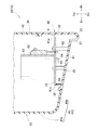
図2を参照する。ディスプレイパネル45は、鉛直方向に延びる前部縦壁部45aと、この前部縦壁部45aの下端から後方に下がり勾配に延び底面部29の一部を構成する延出部45bと、を有している。メインパネル44(図1(a)参照)も同様である。
See FIG. The
図3を併せて参照する。下蓋部材50は、ディスプレイパネル45(前下部パネル43)の延出部45bから連続して後方に下がり勾配に形成された底板部51と、この底板部51の側縁及び後縁に沿って溝状に形成された溝部52と、この溝部52の端部から立ち上げられ側面部27(図1(b)参照)及び後面部26の下端を構成する後部縦壁部53と、底板部51から立ち上げられ幅方向に亘って延びている支持壁部54と、底板部51から立ち上げられ制御基板61を固定するための3つのボス55と、底板部51の前端に形成され延出部45bに係止された係止部56と、溝部52の前面から底面にかけて空けられた底穴部57と、を有している。
See also FIG. The
底面部29は、延出部45bと、底板部51と、溝部52と、から構成されている。底面部29は、前面部25の下端から後面部26の下端まで下がり勾配に設けられている。溝部52は、底面部29の後端且つ下端の部位において溝状に形成されているということができる。
The
支持壁部54は、底板部51の前部に形成されている。支持壁部54は、制御基板61が載置されることにより、制御基板61を支持している部位である。
The
3つのボス55は、略二等辺三角形状に配置されている。底板部51の前部且つ左右の端部に2つと、底板部51の後部且つ幅方向中央に1つが形成されている。
The three
図1(a)を参照する。底穴部57は、本体部20を正面(前面)から見た場合に、視認することができるように形成されている。
See FIG. 1 (a). The
図2及び図3を参照する。制御基板61の上面には、ヒータ31(図1参照)に流す電流を制御するための半導体スイッチング素子としてトライアック62が実装されていると共に、トライアック62が発した熱を放熱するためのヒートシンク63が載せられている。制御基板61の下面には、フォトトライアック64が実装されている。
See FIGS. 2 and 3. A
暖房装置10の幅方向(正面から見た場合)を基準として、トライアック62及びフォトトライアック64は、少なくとも一部がラップするよう配置されている。
The
制御基板61の縁は、後面部26に沿って配置された後辺部61aと、この後辺部61aの左右の端部から前方に向かって延びる左右の側辺部61b、61bと、これらの左右の側辺部61b、61bの前端同士をつなぐ前辺部61cと、からなる。
The edges of the
ヒートシンク63は、後辺部61aよりも前辺部61cに近い位置に配置されている。
The
図2を参照する。制御基板61は、後面部26に対して隙間Sを開けて配置されている。底穴部57は、隙間Sの下方に形成されている。
See FIG. The
ところで、図2は、図1の2−2線断面図であり、正面図を基準とした断面図である。この状態において、同じ断面上に底穴部57、トライアック62、ヒートシンク63、及び、フォトトライアック64が表れている。このことから、底穴部57は、本体部20を正面から見た状態を基準として、トライアック62、ヒートシンク63、及び、フォトトライアック64に重なる位置に空けられている。
By the way, FIG. 2 is a sectional view taken along line 2-2 of FIG. 1, which is a sectional view based on a front view. In this state, the
以上に説明した本発明は、以下の効果を奏する。 The present invention described above has the following effects.
図2を参照する。底面部29は、本体部20内に浸入した水滴を抜くために空けられた底穴部57を有している。本体部20が被った水は、底面部29に形成された底穴部57から外部へ排出される。これにより、制御基板61が水に浸かることを抑制することができる。
See FIG. The
加えて、底穴部57は、本体部20を正面から見た状態を基準として、トライアック62に重なる位置に空けられている。本体部20内の暖かい空気は、上方へ流れる。これにより、本体部20の下部に形成された底穴部57から冷たい空気が本体部20内に取り込まれる。底穴部57は、トライアック62の近傍に形成されている。底穴部57から取り込まれた冷たい空気によりトライアック62を冷却することができる。
In addition, the
加えて、制御基板61は、後面部26に対して隙間Sを開けて配置されている。トライアック62を冷却し温められた空気は、制御基板61と後面部26との間の隙間Sから上方に流れる。温められた空気がトライアック62の周辺に留まることを抑制しつつ、冷たい空気を底穴部57から取り入れることができる。これにより、効率よくトライアック62を冷却することができる。
In addition, the
以上により、制御基板61が水に浸かることを抑制しつつ、トライアック62の放熱を行うことのできる暖房装置10を提供することができる。本発明は、トライアック62の近傍となる位置に底穴部57を形成することと、制御基板61を後面部26から離して配置することにより、課題を解決した。即ち、本発明によれば、部品点数を増加させることなく、制御基板61が水に浸かることを抑制しつつ、トライアック62の放熱を行うことのできる暖房装置10を提供することができる。
As described above, it is possible to provide the
さらに、ヒートシンク63は、後辺部61aよりも前辺部61cに近い位置に配置されているとともに、底穴部57は、隙間Sの下方に形成されている。トライアック62の熱は、ヒートシンクにより放熱される。このとき、ヒートシンク63の配置される前辺部61cに近い部位は、効率よく放熱を行うことができる。一方、前辺部61cに近い部位に比べて、後辺部61aに近い部位は、熱が篭もりやすい。隙間Sの下方に形成された底穴部57から空気が吸い込まれることにより、後辺部61a近傍の熱を放熱することができる。トライアック62の発した熱をより効率的に放熱することができる。
Further, the
特に、隙間Sの下方に底穴部57が形成されているため、底穴部57から隙間までの距離を短くすることができる。底穴部57から導入された空気をより確実に隙間Sから上方に流すことができる。これにより、放熱の効率をより高めることができる。
In particular, since the
さらに、底面部29は、前面部25の下端から後面部26の下端まで下がり勾配に設けられ、底穴部57は、底面部29の後端且つ下端に形成された溝部52に形成されている。これにより、底面部29に落下した水を確実に底穴部57に導き、外部へ排出することができる。加えて、溝部52が形成されていることにより、底面部29の強度を高めることができる。強度を高めた溝部52に底穴部57を形成することにより、穴を空けることにより低下する強度を補うことができる。
Further, the
ヒートシンク63は、後辺部61aよりも前辺部61cに近い位置に配置されているとともに、底面部29は、後に向かって下がり勾配に形成されている。加えて、底面部29のなかのヒートシンク63が配置されるよりも前方の位置には、本体部20の幅方向に亘って立ち上げられ制御基板61を下方から支持する支持壁部54が形成されている。後方に向かって下がり勾配とすることにより水を後方に確実に流すことができる。一方、重量物であるヒートシンク63支持するために支持壁部54を形成した。ヒートシンク63は前方に寄せて配置されているため、制御基板61は、前方の部位に下向きの力が加わる。このため、ヒートシンク63よりも前方に支持壁部54を形成することが好ましい。このとき、底面部29は、後方に向かって下がり勾配とされているため、より前方に支持壁部54を形成することにより、支持壁部54の高さを低くすることができる。
The
底穴部57は、溝部52の前面に形成されている。図1を併せて参照する。これにより、本体部20を正面から見た際に、底穴部57を視認することができる。通常、ユーザは、本体部20の前面部25を自身に向けて暖房装置10を使用する。底穴部57を正面から視認可能な位置に形成することにより、底穴部57に水が付着していることを容易に認識することができる。底穴部57に付着した水を拭き取ることにより、底穴部57から再び空気を取り入れることができ、トライアック62を冷却することができる。
The
尚、本発明による暖房装置は、ヒータを2本有しているものを例に説明したが、ヒータの数は、1本や3本であってもよい。即ち、ヒータの数は2本に限られず、任意の本数を用いることができる。 Although the heating device according to the present invention has been described by taking an example of having two heaters, the number of heaters may be one or three. That is, the number of heaters is not limited to two, and any number can be used.
加えて、本発明による暖房装置は、半導体スイッチング素子としてトライアックを例に説明したが、パワーMOSFETやサイリスタにより構成してもよいものである。 In addition, although the heating device according to the present invention has been described by taking a triac as an example of a semiconductor switching element, it may be configured by a power MOSFET or a thyristor.
本発明の作用及び効果を奏する限りにおいて、本発明は実施例に限定されるものではない。 The present invention is not limited to the examples as long as the actions and effects of the present invention are exhibited.
本発明の暖房装置は、家庭用の電気ストーブに好適である。 The heating device of the present invention is suitable for a household electric stove.
10…暖房装置
20…本体部
25…前面部
26…後面部
29…底面部
31…ヒータ
52…溝部
57…底穴部
61…制御基板
61a…後辺部
61b…側辺部
61c…前辺部
62…トライアック(半導体スイッチング素子)
63…ヒートシンク
S…隙間
10 ...
63 ... Heat sink S ... Gap
Claims (2)
前記本体部には、外部から視認可能なヒータ及びこのヒータの下方に配置され前記ヒータを制御する制御基板が収納されている暖房装置において、
前記本体部は、上下方向に延び前記ヒータを視認可能な前面部と、この前面部に沿って形成され前記ヒータの後方を覆っている後面部と、これらの前面部及び後面部の下端に設けられた底面部と、を有し、
前記制御基板は、前記底面部から立ち上げられたボスの上端に固定されていると共に、前記制御基板には、半導体スイッチング素子が実装され、
前記底面部は、前記前面部の下端から前記後面部の下端まで下がり勾配に設けられ、後端且つ下端の部位が溝状に形成された溝部とされていると共に、前記本体部内に浸入した水滴を抜くために空けられた底穴部を有し、
前記底穴部は、前記溝部のうち、前記本体部を正面から見た状態を基準として、前記半導体スイッチング素子に重なる位置に空けられ、
前記制御基板は、前記後面部に対して隙間を開けて配置され、
前記本体部を正面から見た場合に、前記底穴部が視認可能であることを特徴とする暖房装置。 It has a base portion, a strut portion raised from the base portion, and a main body portion rotatably supported by the front portion of the strut portion.
The body portion, the heating device that has been disposed below the heater capable and the heater seen from the outside is controlled substrate (Scheme 13) accommodated for controlling said heater,
The main body portion is provided at a front portion extending in the vertical direction so that the heater can be visually recognized, a rear surface portion formed along the front surface portion and covering the rear of the heater, and lower ends of the front surface portion and the rear surface portion thereof. With the bottom part ,
The control board is fixed to the upper end of a boss raised from the bottom surface portion , and a semiconductor switching element is mounted on the control board.
The bottom surface portion is provided with a downward slope from the lower end of the front surface portion to the lower end of the rear surface portion, and the rear end and the lower end portion is a groove portion formed in a groove shape, and water droplets that have infiltrated into the main body portion. Has a bottom hole drilled to pull out,
The bottom hole portion is formed at a position overlapping the semiconductor switching element in the groove portion with reference to a state in which the main body portion is viewed from the front.
The control board is arranged with a gap with respect to the rear surface portion .
When viewed said body portion from the front, the heating device the bottom hole is characterized viewable der Rukoto.
前記制御基板には、前記半導体スイッチング素子の発した熱を放熱するためのヒートシンクが載せられ、
前記ヒートシンクは、前記後辺部よりも前記前辺部に近い位置に配置され、
前記底穴部は、前記隙間の下方に形成されていることを特徴とする請求項1に記載の暖房装置。 The edges of the control board are a rear side portion arranged along the rear surface portion, left and right side side portions extending forward from the left and right end portions of the rear side portion, and these left and right side side portions. It consists of a front side that connects the front ends of the
A heat sink for dissipating heat generated by the semiconductor switching element is mounted on the control board.
The heat sink is arranged at a position closer to the front side portion than the rear side portion.
The heating device according to claim 1, wherein the bottom hole portion is formed below the gap.
Priority Applications (1)
| Application Number | Priority Date | Filing Date | Title |
|---|---|---|---|
| JP2017057085A JP6840586B2 (en) | 2017-03-23 | 2017-03-23 | Heating device |
Applications Claiming Priority (1)
| Application Number | Priority Date | Filing Date | Title |
|---|---|---|---|
| JP2017057085A JP6840586B2 (en) | 2017-03-23 | 2017-03-23 | Heating device |
Publications (2)
| Publication Number | Publication Date |
|---|---|
| JP2018159511A JP2018159511A (en) | 2018-10-11 |
| JP6840586B2 true JP6840586B2 (en) | 2021-03-10 |
Family
ID=63795539
Family Applications (1)
| Application Number | Title | Priority Date | Filing Date |
|---|---|---|---|
| JP2017057085A Active JP6840586B2 (en) | 2017-03-23 | 2017-03-23 | Heating device |
Country Status (1)
| Country | Link |
|---|---|
| JP (1) | JP6840586B2 (en) |
Family Cites Families (4)
| Publication number | Priority date | Publication date | Assignee | Title |
|---|---|---|---|---|
| JPS5414228Y2 (en) * | 1973-02-12 | 1979-06-13 | ||
| JPS5824093Y2 (en) * | 1978-09-13 | 1983-05-23 | 松下電器産業株式会社 | Cooking device |
| JPH01225836A (en) * | 1988-03-04 | 1989-09-08 | Mitsubishi Electric Corp | Electric heater |
| JP3473051B2 (en) * | 1993-08-31 | 2003-12-02 | 松下電器産業株式会社 | Electric heater |
-
2017
- 2017-03-23 JP JP2017057085A patent/JP6840586B2/en active Active
Also Published As
| Publication number | Publication date |
|---|---|
| JP2018159511A (en) | 2018-10-11 |
Similar Documents
| Publication | Publication Date | Title |
|---|---|---|
| US7269009B2 (en) | Case for covering electronic parts and display apparatus including the same | |
| EP2225923B1 (en) | Inverter | |
| CA2156520A1 (en) | Unitary seat support with integrated electronics | |
| KR101282916B1 (en) | Induction range with a function of improved impact strength and heat resistance | |
| JP4822443B2 (en) | Vehicle headlamp | |
| JP4234541B2 (en) | Balance with heat dissipation device | |
| JP2022038624A (en) | Induction heating cooker | |
| JP5505052B2 (en) | Vehicle lighting | |
| JP5092566B2 (en) | Induction heating cooker | |
| JP2016216194A (en) | Elevator control device | |
| JP6893196B2 (en) | Induction heating cooker | |
| JP2018159511A (en) | Heating system | |
| JP4494379B2 (en) | Induction heating cooker | |
| JP7190974B2 (en) | heater | |
| JP3492250B2 (en) | Electric rice cooker | |
| JP2017204901A (en) | Outdoor board | |
| KR101576828B1 (en) | electric range | |
| JP6282966B2 (en) | Motor control unit | |
| JP5031010B2 (en) | Induction heating cooker | |
| KR20210021647A (en) | Apparatus for ptc heater | |
| JP3209655U (en) | Heat dissipation structure of control panel | |
| JP5886250B2 (en) | Gas stove | |
| JP6286797B2 (en) | Light control device and light control panel using the same | |
| JP4321358B2 (en) | Electric warming device | |
| CN215226844U (en) | Pot body assembly of cooking utensil and cooking utensil with pot body assembly |
Legal Events
| Date | Code | Title | Description |
|---|---|---|---|
| A621 | Written request for application examination |
Free format text: JAPANESE INTERMEDIATE CODE: A621 Effective date: 20190826 |
|
| A977 | Report on retrieval |
Free format text: JAPANESE INTERMEDIATE CODE: A971007 Effective date: 20200729 |
|
| A131 | Notification of reasons for refusal |
Free format text: JAPANESE INTERMEDIATE CODE: A131 Effective date: 20200901 |
|
| A521 | Request for written amendment filed |
Free format text: JAPANESE INTERMEDIATE CODE: A523 Effective date: 20201005 |
|
| TRDD | Decision of grant or rejection written | ||
| A01 | Written decision to grant a patent or to grant a registration (utility model) |
Free format text: JAPANESE INTERMEDIATE CODE: A01 Effective date: 20210209 |
|
| A61 | First payment of annual fees (during grant procedure) |
Free format text: JAPANESE INTERMEDIATE CODE: A61 Effective date: 20210217 |
|
| R150 | Certificate of patent or registration of utility model |
Ref document number: 6840586 Country of ref document: JP Free format text: JAPANESE INTERMEDIATE CODE: R150 |
|
| R250 | Receipt of annual fees |
Free format text: JAPANESE INTERMEDIATE CODE: R250 |
|
| R250 | Receipt of annual fees |
Free format text: JAPANESE INTERMEDIATE CODE: R250 |
|
| R250 | Receipt of annual fees |
Free format text: JAPANESE INTERMEDIATE CODE: R250 |