JP6844937B2 - Inert gas generator - Google Patents
Inert gas generator Download PDFInfo
- Publication number
- JP6844937B2 JP6844937B2 JP2019541211A JP2019541211A JP6844937B2 JP 6844937 B2 JP6844937 B2 JP 6844937B2 JP 2019541211 A JP2019541211 A JP 2019541211A JP 2019541211 A JP2019541211 A JP 2019541211A JP 6844937 B2 JP6844937 B2 JP 6844937B2
- Authority
- JP
- Japan
- Prior art keywords
- electrode
- electrode unit
- gas
- cooling water
- unit base
- Prior art date
- Legal status (The legal status is an assumption and is not a legal conclusion. Google has not performed a legal analysis and makes no representation as to the accuracy of the status listed.)
- Active
Links
Images





Classifications
-
- H—ELECTRICITY
- H01—ELECTRIC ELEMENTS
- H01J—ELECTRIC DISCHARGE TUBES OR DISCHARGE LAMPS
- H01J37/00—Discharge tubes with provision for introducing objects or material to be exposed to the discharge, e.g. for the purpose of examination or processing thereof
- H01J37/32—Gas-filled discharge tubes
- H01J37/32431—Constructional details of the reactor
- H01J37/32532—Electrodes
- H01J37/32541—Shape
-
- H—ELECTRICITY
- H01—ELECTRIC ELEMENTS
- H01J—ELECTRIC DISCHARGE TUBES OR DISCHARGE LAMPS
- H01J37/00—Discharge tubes with provision for introducing objects or material to be exposed to the discharge, e.g. for the purpose of examination or processing thereof
- H01J37/32—Gas-filled discharge tubes
- H01J37/32009—Arrangements for generation of plasma specially adapted for examination or treatment of objects, e.g. plasma sources
- H01J37/32348—Dielectric barrier discharge
-
- H—ELECTRICITY
- H01—ELECTRIC ELEMENTS
- H01J—ELECTRIC DISCHARGE TUBES OR DISCHARGE LAMPS
- H01J37/00—Discharge tubes with provision for introducing objects or material to be exposed to the discharge, e.g. for the purpose of examination or processing thereof
- H01J37/32—Gas-filled discharge tubes
- H01J37/32009—Arrangements for generation of plasma specially adapted for examination or treatment of objects, e.g. plasma sources
- H01J37/32018—Glow discharge
- H01J37/32036—AC powered
-
- H—ELECTRICITY
- H01—ELECTRIC ELEMENTS
- H01J—ELECTRIC DISCHARGE TUBES OR DISCHARGE LAMPS
- H01J37/00—Discharge tubes with provision for introducing objects or material to be exposed to the discharge, e.g. for the purpose of examination or processing thereof
- H01J37/32—Gas-filled discharge tubes
- H01J37/32431—Constructional details of the reactor
- H01J37/3244—Gas supply means
-
- H—ELECTRICITY
- H01—ELECTRIC ELEMENTS
- H01J—ELECTRIC DISCHARGE TUBES OR DISCHARGE LAMPS
- H01J37/00—Discharge tubes with provision for introducing objects or material to be exposed to the discharge, e.g. for the purpose of examination or processing thereof
- H01J37/32—Gas-filled discharge tubes
- H01J37/32431—Constructional details of the reactor
- H01J37/32458—Vessel
-
- H—ELECTRICITY
- H01—ELECTRIC ELEMENTS
- H01J—ELECTRIC DISCHARGE TUBES OR DISCHARGE LAMPS
- H01J37/00—Discharge tubes with provision for introducing objects or material to be exposed to the discharge, e.g. for the purpose of examination or processing thereof
- H01J37/32—Gas-filled discharge tubes
- H01J37/32431—Constructional details of the reactor
- H01J37/32532—Electrodes
- H01J37/32568—Relative arrangement or disposition of electrodes; moving means
-
- H—ELECTRICITY
- H01—ELECTRIC ELEMENTS
- H01J—ELECTRIC DISCHARGE TUBES OR DISCHARGE LAMPS
- H01J37/00—Discharge tubes with provision for introducing objects or material to be exposed to the discharge, e.g. for the purpose of examination or processing thereof
- H01J37/32—Gas-filled discharge tubes
- H01J37/32431—Constructional details of the reactor
- H01J37/32532—Electrodes
- H01J37/32577—Electrical connecting means
-
- H—ELECTRICITY
- H05—ELECTRIC TECHNIQUES NOT OTHERWISE PROVIDED FOR
- H05H—PLASMA TECHNIQUE; PRODUCTION OF ACCELERATED ELECTRICALLY-CHARGED PARTICLES OR OF NEUTRONS; PRODUCTION OR ACCELERATION OF NEUTRAL MOLECULAR OR ATOMIC BEAMS
- H05H1/00—Generating plasma; Handling plasma
- H05H1/24—Generating plasma
- H05H1/2406—Generating plasma using dielectric barrier discharges, i.e. with a dielectric interposed between the electrodes
- H05H1/2443—Generating plasma using dielectric barrier discharges, i.e. with a dielectric interposed between the electrodes the plasma fluid flowing through a dielectric tube
- H05H1/2465—Generating plasma using dielectric barrier discharges, i.e. with a dielectric interposed between the electrodes the plasma fluid flowing through a dielectric tube the plasma being activated by inductive coupling, e.g. using coiled electrodes
-
- H—ELECTRICITY
- H01—ELECTRIC ELEMENTS
- H01J—ELECTRIC DISCHARGE TUBES OR DISCHARGE LAMPS
- H01J2237/00—Discharge tubes exposing object to beam, e.g. for analysis treatment, etching, imaging
- H01J2237/32—Processing objects by plasma generation
- H01J2237/33—Processing objects by plasma generation characterised by the type of processing
- H01J2237/332—Coating
- H01J2237/3321—CVD [Chemical Vapor Deposition]
-
- H—ELECTRICITY
- H05—ELECTRIC TECHNIQUES NOT OTHERWISE PROVIDED FOR
- H05H—PLASMA TECHNIQUE; PRODUCTION OF ACCELERATED ELECTRICALLY-CHARGED PARTICLES OR OF NEUTRONS; PRODUCTION OR ACCELERATION OF NEUTRAL MOLECULAR OR ATOMIC BEAMS
- H05H1/00—Generating plasma; Handling plasma
- H05H1/24—Generating plasma
- H05H1/2406—Generating plasma using dielectric barrier discharges, i.e. with a dielectric interposed between the electrodes
- H05H1/2443—Generating plasma using dielectric barrier discharges, i.e. with a dielectric interposed between the electrodes the plasma fluid flowing through a dielectric tube
Landscapes
- Physics & Mathematics (AREA)
- Engineering & Computer Science (AREA)
- Plasma & Fusion (AREA)
- Chemical & Material Sciences (AREA)
- Analytical Chemistry (AREA)
- Spectroscopy & Molecular Physics (AREA)
- Fluid Mechanics (AREA)
- Power Engineering (AREA)
- Plasma Technology (AREA)
- Chemical Vapour Deposition (AREA)
Description
本発明は、半導体成膜装置に用いる並行平板電極型の電極構造を有し、誘電体バリア放電を用いた活性ガス生成装置に関する。 The present invention relates to an active gas generating apparatus having a parallel plate electrode type electrode structure used for a semiconductor film forming apparatus and using a dielectric barrier discharge.
並行平板電極型の電極構造を有し、誘電体バリア放電を用いた活性ガス生成装置の設置位置の1つとして、ウェハ等の処理対象物の上方に配置する態様がある。この態様の場合、活性ガスを処理対象物全体に均等に吹付ける必要があるため、活性ガス生成装置と処理対象物の間にガス均等吹付け用のシャワープレートを配置するのが一般的であった。 It has a parallel flat plate electrode type electrode structure, and as one of the installation positions of an active gas generator using a dielectric barrier discharge, there is an embodiment in which it is arranged above an object to be processed such as a wafer. In this embodiment, since it is necessary to spray the active gas evenly over the entire object to be treated, it is common to arrange a shower plate for evenly spraying the gas between the active gas generator and the object to be treated. It was.
しかしながら、シャワープレート内の活性ガス通過領域は誘電体バリア放電に関与しない非放電空間となるため、シャワープレート内の活性ガス通過領域を活性ガスが通過する時間帯は、活性ガスが失活する時間帯となる。このため、活性ガス生成装置が窒素ラジカル等の極短寿命な活性ガスを生成する場合、シャワープレート通過中にラジカルの失活が著しく促進されてしまう。 However, since the active gas passage region in the shower plate is a non-discharge space that does not participate in the dielectric barrier discharge, the time zone in which the active gas passes through the active gas passage region in the shower plate is the time during which the active gas is deactivated. It becomes a band. Therefore, when the active gas generator generates an extremely short-lived active gas such as nitrogen radicals, the deactivation of radicals is remarkably promoted while passing through the shower plate.
このように、活性ガス生成装置にシャワープレートを用いると、活性ガスが失活する現象を増長させてしまうため、望ましくない。 As described above, it is not desirable to use a shower plate for the active gas generator because it increases the phenomenon that the active gas is deactivated.
シャワープレートを用いない従来の活性ガス生成装置として、例えば、特許文献1に開示された大気圧プラズマ反応装置がある。
As a conventional active gas generating device that does not use a shower plate, for example, there is an atmospheric pressure plasma reactor disclosed in
特許文献1で開示された第1の従来技術では、対向配置した平板状の電極を縦型に配置し、電極間の放電で生成した活性ガスを基板に吹付ける電極構造を採用している。第1の従来技術は、大面積基板への処理対応として電極構造を複数セット配置している。
The first prior art disclosed in
このように、第1の従来技術では、電極構造の数を増やし、複数の電極構造を採用することにより、基板面積に応じた対応が容易に可能となる。 As described above, in the first conventional technique, by increasing the number of electrode structures and adopting a plurality of electrode structures, it is possible to easily respond according to the substrate area.
シャワープレートを用いない他の活性ガス生成装置として、例えば、特許文献2に開示されたプラズマ処理装置がある。
As another active gas generating device that does not use a shower plate, for example, there is a plasma processing device disclosed in
特許文献2で開示された第2の従来技術では、水平方向に対向配置した平板状電極の一方に複数個のガス噴出孔を設けることにより、シャワープレートを不要にし、かつ、大型基板への処理を可能としている。
In the second prior art disclosed in
特許文献2の段落[0022]、図1及び図2に第1の基本構成が開示されている。具体的な構成は以下の通りである。なお、()内の数字は、特許文献2で用いられた参照符号である。
The first basic configuration is disclosed in paragraph [0022], FIGS. 1 and 2 of
第1の基本構成は、導電性を有さない高圧電極(8)の表面に導電層(12)を形成し、高圧電極(8)の下方に位置し導電性を有さない接地電極(7)に、接地された金属板(2)を接触させる構造を採用している。 The first basic configuration is to form a conductive layer (12) on the surface of the non-conductive high-voltage electrode (8), and to be located below the high-voltage electrode (8) and to have a non-conductive ground electrode (7). ) Adopts a structure in which a grounded metal plate (2) is brought into contact.
さらに、特許文献2の段落[0063]及び図9に第2の基本構成が開示されている。具体的な構成は以下の通りである。なお、()内の数字は、特許文献2で用いられた参照符号である。
Further, paragraph [0063] of
第2の基本構成では、第1の基本構成に加え、接地導電層(41)を接地電極(7)内部に埋設した構造を採用している。 In the second basic configuration, in addition to the first basic configuration, a structure in which the ground conductive layer (41) is embedded inside the ground electrode (7) is adopted.
特許文献1で開示された第1の従来技術では、複数の電極構造を採用することにより、比較的大きな面積の処理対象物に対応可能な装置を実現することができる。
In the first prior art disclosed in
しかし、第1の従来技術で複数の電極構造を採用すると、複数の電極構造それぞれに高圧電極及び接地電極を設けなくてはならず、その分、装置構造が複雑化する。さらに、第1の従来技術では、原料ガスの通過方向が縦方向なため活性ガスの濃度増加のためには、電極構造を構成する高圧電極及び接地電極の縦方向の形成長を十分長くすることが必要となり、必然的に装置高さが高くなり、装置の大型化を招いてしまう。 However, if a plurality of electrode structures are adopted in the first conventional technique, a high-voltage electrode and a ground electrode must be provided for each of the plurality of electrode structures, which complicates the device structure. Further, in the first prior art, since the raw material gas passes in the vertical direction, the vertical formation lengths of the high-pressure electrode and the ground electrode constituting the electrode structure are sufficiently long in order to increase the concentration of the active gas. Inevitably, the height of the device becomes high, which leads to an increase in the size of the device.
このように、特許文献1で開示された第1の従来技術では、装置構造の複雑化、大型化を招いてしまうという問題点があった。
As described above, the first prior art disclosed in
次に、特許文献2で開示された第2の従来技術について検討する。なお、()内の数字は、特許文献2で用いられた参照符号である。
Next, the second prior art disclosed in
上述した第1の基本構成では、導電層(12)の端部等の表面における電界強度が非常に高くなるため、放電部(3)のガス層に絶縁破壊が生じ、それによって金属の導電層(12)に異常放電が発生することにより、放電部(3)にパーティクルや金属蒸気が生成する。すなわち、導電層(12)の異常放電に伴い、導電層(12)、チャンバー(1)あるいは仕切り板(2)から蒸発した物質が汚染源となる。 In the first basic configuration described above, the electric field strength on the surface such as the end of the conductive layer (12) becomes very high, so that the gas layer of the discharge portion (3) undergoes dielectric breakdown, which causes the conductive layer of metal. When an abnormal discharge occurs in (12), particles and metal vapor are generated in the discharge part (3). That is, the substance evaporated from the conductive layer (12), the chamber (1) or the partition plate (2) becomes a pollution source due to the abnormal discharge of the conductive layer (12).
導電層(12)の表層と電極間の放電場(空隙(9))は繋がっているため、放電場へガスを輸送する過程で導電層(12)の蒸発分子が活性ガス中に混入、基板(15)を汚染する恐れがあった。 Since the discharge field (void (9)) between the surface layer of the conductive layer (12) and the electrode is connected, the evaporated molecules of the conductive layer (12) are mixed in the active gas in the process of transporting the gas to the discharge field, and the substrate. There was a risk of contaminating (15).
このように、第2の従来技術の第1の基本構成では、放電部(3)にパーティクルや金属蒸気が生成し、基板(15)を汚染する恐れがあるという問題点があった。 As described above, in the first basic configuration of the second prior art, there is a problem that particles and metal vapors are generated in the discharge portion (3) and may contaminate the substrate (15).
上述した基板(15)を汚染する恐れを確実に防止するためには放電部(3)における絶縁距離を十分大きくとる必要がある。しかしながら、絶縁距離を大きくとると必然的に装置構成の大型化を招くため、望ましくない。 In order to surely prevent the risk of contaminating the above-mentioned substrate (15), it is necessary to take a sufficiently large insulation distance in the discharge portion (3). However, increasing the insulation distance inevitably leads to an increase in the size of the device configuration, which is not desirable.
一方、上述した特許文献2の第2の基本構成では、高圧電極(8)の導電層(12)は、第1の基本構成と同様、電極表面に露出した構造ではある。高圧電極も接地電極と同様の処置を講ずることで高圧側・接地側両方の導電層を露出させないものとすることが理論的に可能となる。
On the other hand, in the second basic configuration of
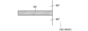
図15は第2の従来技術における第2の基本構成の断面構造を示す断面図である。同図に示す、空隙109が空隙(9)に対応し、第一電極107が一方接地電極(7)に対応し、細孔110が細孔(10)に対応し、接地導電層141が接地導電層(41)に対応し、接地隙間142が接地隙間(42)に対応する。
FIG. 15 is a cross-sectional view showing a cross-sectional structure of a second basic configuration in the second prior art. As shown in the figure, the
同図に示すように、接地導電層141の開口領域H141は細孔110を含み、細孔110より広い形状で形成されているため、電極ユニット100と接地導電層141との間に接地隙間142が生じている。この接地隙間142は、接地導電層141が形成されていない。
As shown in the figure, since the opening region H141 of the ground
したがって、電極間の放電場となる空隙109において、接地隙間142の上方の領域は非放電空間となり、この非放電空間をガスが通過する際には活性ガスが失活するだけとなり、活性ガスの濃度低下を招いてしまう。
Therefore, in the
次に、接地導電層141を改良し、接地隙間142の無い状態(細孔110と本体ポール部の開口領域H141の開口領域とを同じ大きさにする)に変更する変形例を考える。
Next, consider a modified example in which the ground
図16は、第2の従来技術における第2の基本構成の変形例の断面構造を示す断面図である。図16で示す領域は、図15の着目領域R7及びその近傍領域を拡大して示した領域に相当する。 FIG. 16 is a cross-sectional view showing a cross-sectional structure of a modified example of the second basic configuration in the second prior art. The region shown in FIG. 16 corresponds to the region of interest R7 in FIG. 15 and the region in the vicinity thereof, which is enlarged and shown.
第2の基本構成の変形例では、細孔110を断面方向に観察すると接地導電層141が細孔110に露出した状態となっている。このため、接地導電層141の露出部近傍の細孔110で絶縁破壊が発生した際には、接地導電層141の導電層成分がコンタミとなって外部に放出されることになる。
In the second modification of the basic configuration, when the
このように、第2の従来技術の第2の基本構成(図15)では、活性ガスの濃度低下を招く問題があり、第2の基本構成の変形例(図16)では、コンタミが発生してしまう問題点があった。 As described above, the second basic configuration (FIG. 15) of the second prior art has a problem of causing a decrease in the concentration of the active gas, and in the modified example of the second basic configuration (FIG. 16), contamination occurs. There was a problem that it would end up.
本発明では、上記のような問題点を解決し、装置構成の簡略化及び小型化を図り、かつ、活性ガスが失活する現象を抑制することができる活性ガス生成装置を提供することを目的とする。 An object of the present invention is to provide an active gas generator capable of solving the above-mentioned problems, simplifying and downsizing the apparatus configuration, and suppressing the phenomenon of deactivation of the active gas. And.
この発明に係る活性ガス生成装置は、誘電体バリア放電が発生する放電空間に供給された原料ガスを活性化して活性ガスを生成する活性ガス生成装置であって、第1の電極及び第2の電極を有し、外部より交流電圧を受ける電極ユニットベースと、前記電極ユニットベースの表面上に設けられる電極ユニット蓋と、前記電極ユニット蓋の表面上に設けられ、上方から付与される押圧力で電極ユニット蓋を押圧する電極押え板と、前記電極ユニットベース、前記電極ユニット蓋及び前記電極押え板を収容する装置筐体とを備え、前記電極ユニットベースは、表面から所定の形成深さで設けられる第1及び第2の電極用溝と、前記第1及び第2の電極用溝に埋め込まれて設けられ、各々が導電性を有する前記第1及び第2の電極と、前記電極ユニットベース内に形成され、原料ガスが通過するガス内部流路とを含み、前記ガス内部流路は平面視して螺旋状に設けられ、前記第1及び第2の電極は前記ガス内部流路と共に平面視して螺旋状に設けられ、第1及び第2の電極は端部に第1及び第2の導通点を有し、前記第1及び第2の電極は、前記電極ユニットベースの一部及び前記ガス内部流路を挟んで互いに対向するように、前記ガス内部流路の両側に配置され、前記第1及び第2の電極間における前記ガス内部流路内の領域が前記放電空間となり、前記交流電圧を受けることにより前記放電空間に誘電体バリア放電が発生され、前記電極ユニットベースは、裏面に設けられる少なくとも一つのガス噴出口をさらに含み、前記少なくとも一つのガス噴出口は前記放電空間の下方に前記ガス内部流路に連通して設けられ、前記放電空間に供給された原料ガスを活性化して得られる活性ガスが、前記少なくとも一つのガス噴出口から噴出され、前記電極ユニット蓋は、前記電極ユニットベースの前記ガス内部流路に繋がるように設けられるガス中継穴と、平面視して前記第1及び第2の導通点に合致する領域に設けられる第1及び第2の貫通穴とを有し、前記ガス中継穴、前記第1及び第2の貫通穴は前記電極ユニット蓋を貫通し、前記電極押え板は、平面視して前記第1の貫通穴を含み前記第1の貫通穴より広い形状の開口部と、平面視して前記ガス中継穴と合致する領域に設けられるガス供給穴とを有し、前記第2の貫通穴を介して前記第2の導通点と電気的に接続される。 The active gas generator according to the present invention is an active gas generator that activates a raw material gas supplied to a discharge space where a dielectric barrier discharge is generated to generate an active gas, and is a first electrode and a second electrode. An electrode unit base having electrodes and receiving an AC voltage from the outside, an electrode unit lid provided on the surface of the electrode unit base, and a pressing force provided on the surface of the electrode unit lid and applied from above. The electrode holding plate for pressing the electrode unit lid, the electrode unit base, the electrode unit lid, and a device housing for accommodating the electrode holding plate are provided, and the electrode unit base is provided at a predetermined formation depth from the surface. The first and second electrode grooves and the first and second electrodes embedded in the first and second electrode grooves and each having conductivity, and the inside of the electrode unit base. The gas internal flow path is provided in a spiral shape in a plan view, and the first and second electrodes are formed in a plan view together with the gas internal flow path. The first and second electrodes have first and second conduction points at the ends, and the first and second electrodes are a part of the electrode unit base and the above. It is arranged on both sides of the gas internal flow path so as to face each other across the gas internal flow path, and the region in the gas internal flow path between the first and second electrodes serves as the discharge space and the AC. Upon receiving the voltage, a dielectric barrier discharge is generated in the discharge space, the electrode unit base further includes at least one gas outlet provided on the back surface, and the at least one gas outlet is below the discharge space. the gas internal channel communicating provided et al is the active gas obtained by activating the supplied raw material gas to the discharge space, the ejected from at least one gas orifice, the electrode unit lid on, a gas relay holes provided so as to be connected to the gas internal channel of the electrode unit base, first and second through-hole that is provided in a region that matches the first and second conductive point in a plan view The gas relay hole, the first and second through holes penetrate the electrode unit lid, and the electrode holding plate includes the first through hole in a plan view and includes the first through hole. It has an opening having a shape wider than the through hole and a gas supply hole provided in a region corresponding to the gas relay hole in a plan view, and the second conduction point and electricity are provided through the second through hole. Is connected.
請求項1記載の本願発明である活性ガス生成装置の電極ユニットベースは、平面視して螺旋状に設けられるガス内部流路と、放電空間の下方にガス内部流路に連通して設けられる少なくとも一つのガス噴出口とを含んでいる。 The electrode unit base of the active gas generator according to the first aspect of the present invention is provided at least in communication with the gas internal flow path provided in a spiral shape in a plan view and the gas internal flow path below the discharge space. Includes one gas outlet.
したがって、請求項1記載の本願発明である活性ガス生成装置は、少なくとも一つのガス噴出口と放電空間との間に、誘電体バリア放電に関与しない非放電空間が形成されないため、活性ガスが失活する現象を効果的に抑制する効果を奏する。
Therefore, in the active gas generator according to the present invention according to
さらに、電極ユニットベースに関し、少なくとも一つのガス噴出口、第1及び第2の電極並びにガス内部流路を設けるという比較的簡単な構成で上記効果を発揮することがきるため、活性ガス生成装置の装置構成の簡略化を図ることができる。 Further, with respect to the electrode unit base, the above effect can be exhibited with a relatively simple configuration of providing at least one gas outlet, first and second electrodes, and a gas internal flow path. The device configuration can be simplified.
加えて、請求項1記載の本願発明の活性ガス生成装置において、ガス内部流路は平面視して螺旋状に設けられる。このため、電極ユニットベース自体の面積を大きくすることなく、少なくとも一つのガス噴出口からガス濃度が飽和した状態で活性ガスを噴出することができる分、装置の小型化を図ることができる。
In addition, in the active gas generating apparatus of the present invention according to
さらに、請求項1記載の本願発明の活性ガス生成装置における電極ユニット蓋は、平面視して前記第1及び第2の導通点に合致する領域に設けられ、各々が貫通する第1及び第2の導通穴を有する。
Further, the electrode unit lid in the active gas generator of the present invention according to
このため、電極ユニット蓋は、第1及び第2の導通穴を介した第1及び第2の導通点と外部との電気的接続機能を確保しつつ、電極ユニットベースの上方を塞ぐことができる。 Therefore, the electrode unit lid can close the upper part of the electrode unit base while ensuring the electric connection function between the first and second conduction points and the outside through the first and second conduction holes. ..
さらに、電極押え板は、平面視して第1の貫通穴を含み第1の貫通穴より広い形状の開口部を有しているため、第1の導通穴を介した第1の導通点と外部との電気的接続機能を確保することができる。さらに、電極押え板は、第2の導通穴を介して第2の導通点と自身とを電気的に接続することができる。 Further, since the electrode holding plate has an opening having a shape wider than that of the first through hole including the first through hole in a plan view, it can be connected to the first conduction point through the first conduction hole. It is possible to secure an electrical connection function with the outside. Further, the electrode holding plate can electrically connect the second conduction point and itself through the second conduction hole.
加えて、電極押え板は、電極ユニット蓋を安定性良く押さえることができる。 In addition, the electrode pressing plate can stably press the electrode unit lid.
この発明の目的、特徴、局面、および利点は、以下の詳細な説明と添付図面とによって、より明白となる。 Objectives, features, aspects, and advantages of the present invention will become more apparent with the following detailed description and accompanying drawings.
<実施の形態>
(全体構成)
図1はこの発明の実施の形態である活性ガス生成装置10の断面構造を示す説明図である。本実施の形態の活性ガス生成装置10は、誘電体バリア放電が発生する放電空間に供給された原料ガスを活性化して活性ガスを生成する。<Embodiment>
(overall structure)
FIG. 1 is an explanatory view showing a cross-sectional structure of the active
活性ガス生成装置10は装置筐体30、電極ユニット蓋1、電極ユニットベース2、電極冷却板3、発生器ベースフランジ8、冷却水マニホールド37及び高圧端子71を主要構成部として含んでいる。
The
電極ユニットベース2は、第1の電極である高圧電極11と第2の電極である接地電極12とを有し、高圧端子71を介して外部より交流電圧を受ける。
The
電極ユニット蓋1は電極ユニットベース2の表面上に設けられる。電極ユニット蓋1及び電極ユニットベース2はそれぞれ誘電体で構成される。
The
電極押え板である電極冷却板3は電極ユニット蓋1の表面上に設けられ、導電性を有する。また、電極冷却板3は、電極冷却板3の上方に設けられた図示しないバネ等の弾性部材によって付与される押圧力によって電極ユニット蓋1を押圧することができる。
The
装置筐体30は、これら電極ユニットベース2、電極ユニット蓋1及び電極冷却板3を収容空間SP30内に収容している。
The
発生器ベースフランジ8は、電極ユニットベース2の裏面に設けられる複数のガス噴出口6が全て露出するように、中央領域に開口部H8を設けている。
The
さらに、電極ユニットベース2の裏面において、開口部H8の外側に位置する領域が発生器ベースフランジ8の表面上に配置されている。したがって、発生器ベースフランジ8は、電極ユニットベース2を裏面側から支持している。
Further, on the back surface of the
冷却水マニホールド37は発生器ベースフランジ8の表面の一部上おいて、電極ユニット蓋1及び電極ユニットベース2に隣接して配置される。冷却水マニホールド37の表面高さは電極ユニット蓋1の表面高さと一致しており、電極冷却板3は、電極ユニット蓋1に加え冷却水マニホールド37の表面上にも配置される。
The cooling
これら発生器ベースフランジ8及び冷却水マニホールド37の組合せ構造により、後に詳述するように、冷却媒体である冷却水を電極冷却板3内で循環させる冷却媒体循環機構が構成される。したがって、電極冷却板3は電極ユニット蓋1側から電極ユニットベース2を冷却する冷却機能を有している。
The combined structure of the
そして、開口部H8を挟んで一方側(図1の右側)において、電極冷却板3、冷却水マニホールド37及び発生器ベースフランジ8が取付用ネジ48によって連結される。開口部H8を挟んで他方側(図1の左側)において、電極冷却板3と発生器ベースフランジ8とが取付用ネジ48によって直接連結される。
Then, on one side (right side in FIG. 1) of the opening H8, the
このように、取付用ネジ48によって、電極冷却板3、電極ユニット蓋1、電極ユニットベース、及び冷却媒体循環機構(冷却水マニホールド37+発生器ベースフランジ8)は一体的に連結される。また、装置筐体30は取付用ネジ48によって発生器ベースフランジ8に直接連結される。したがって、装置筐体30は発生器ベースフランジ8上に固定される。
In this way, the
さらに、交流電圧を供給する交流電圧供給端子である高圧端子71が装置筐体30の上部に取付用ネジ47によって取り付けされ、後述するように、電極ユニットベース2内の高圧電極11に電気的に接続される。
Further, a high-
装置筐体30の一方側面にガス供給フランジ39が設けられ、ガス供給フランジ39から、原料ガス供給経路33を経由して、収容空間SP30内に原料ガスが供給される。
A
(電極ユニットベース2)
図2は図1で示した電極ユニットベース2の構造を示す斜視図である。図3は図2で示した高圧電極用溝21(第1の電極用溝)のみを特化して示す斜視図である。図4は図2で示した接地電極用溝22(第2の電極用溝)のみを特化して示す斜視図である。図2〜図4にはそれぞれXYZ直交座標系を示している。(Electrode unit base 2)
FIG. 2 is a perspective view showing the structure of the
図5は実施の形態の活性ガス生成装置10に用いられる電極ユニット100の構成概略を示す説明図である。図5にXYZ直交座標系を示している。以下に示す図6〜図8においても、図5と同様に、XYZ直交座標系を示している。
Figure 5 is an explanatory diagram showing the schematic configuration of the
図5に示すように、電極ユニット100は、各々が誘電体で構成される電極ユニット蓋1及び電極ユニットベース2を主要構成部として有している。電極ユニット蓋1は電極ユニットベース2の表面上に設けられる。
As shown in FIG. 5, the
図6は電極ユニットベース2を上方から視た平面構造を示す平面図である。図2及び図6に示すように、電極ユニットベース2は平面視して円状を呈している。
FIG. 6 is a plan view showing a plan structure of the
図2〜図4及び図6に示すように、電極ユニットベース2にはガス通過溝24、高圧電極用溝21、及び接地電極用溝22がそれぞれ電極ユニットベース2の表面から掘られている。ガス通過溝24、高圧電極用溝21及び接地電極用溝22は平面視して螺旋状に形成される。
As shown in FIGS. 2 to 4 and 6, a
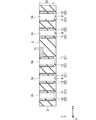
図7は電極ユニットベース2の断面構造を示す断面図である。図6のA−A断面が図7となる。
FIG. 7 is a cross-sectional view showing a cross-sectional structure of the
図7に示すように、ガス通過溝24、高圧電極用溝21及び接地電極用溝22は、それぞれの底面が電極ユニットベース2の底面より少し高い位置になるように掘られている。ガス通過溝24、高圧電極用溝21及び接地電極用溝22の表面からの形成深さは同一の深さD2に設定されている。
As shown in FIG. 7, the
このように、電極ユニットベース2は、表面から同一の形成深さで設けられる第1及び第2の電極用溝である高圧電極用溝21及び接地電極用溝22を有している。
As described above, the
さらに、電極ユニットベース2は、表面から深さD2(所定の形成深さ)で溝状に形成され、ガス内部流路となるガス通過溝24を有している。
Further, the
高圧電極用溝21及び接地電極用溝22は、電極ユニットベース2の一部及びガス通過溝24を挟んで互いに対向するように、電極ユニットベース2内のガス通過溝24の両側面側に配置され、ガス通過溝24と共に平面視して螺旋状に設けられる。
The high-
そして、第1の電極である高圧電極11が第1の電極用溝である高圧電極用溝21に埋め込まれ、第2の電極である接地電極12が第2の電極用溝である接地電極用溝22に埋め込まれている。この際、高圧電極11は、高圧電極用溝21に隙間が生じることなく高圧電極用溝21の全体に亘って埋め込まれ、接地電極12は接地電極用溝22に隙間が生じることなく接地電極用溝22の全体に亘って埋め込まれる。
Then, the high-
そして、図2及び図6に示すように、本実施の形態の活性ガス生成装置10では、電極ユニット100内において、高圧電極11及び接地電極12に関し、平面視して電極ユニットベース2の最外周に接地電極12が位置するように配置されている。
Then, as shown in FIGS. 2 and 6, in the
したがって、高圧電極11及び接地電極12は、電極ユニットベース2の一部及びガス通過溝24を挟んで互いに対向するように、電極ユニットベース2内のガス通過溝24の両側面側に配置され、ガス通過溝24と共に平面視して螺旋状に設けられる。そして、高圧電極11及び接地電極12間におけるガス通過溝24内の領域が放電空間となる。
Therefore, the high-
図8は電極ユニットベース2を下方から視た平面構造を示す平面図である。
FIG. 8 is a plan view showing a plan structure of the
図2及び図6〜図8に示すように、ガス内部流路であるガス通過溝24の底面下の電極ユニットベース2の領域を貫通する複数のガス噴出口6が互いに離散して選択的に設けられている。複数のガス噴出口6は、放電空間の下方にガス通過溝24の底面に繋がって設けられる。すなわち、複数のガス噴出口6はガス通過溝24に連通している。したがって、ガス通過溝24内で生成された活性ガスを複数のガス噴出口6から外部に噴出することができる。
As shown in FIGS. 2 and 6 to 8, a plurality of
電極ユニット蓋1及び電極ユニットベース2はそれぞれアルミナ等の誘電体で構成される。
The
図2、図3,図6及び図7に示すように、電極ユニットベース2の表面の中心部に高圧電極11の高圧導通点P1が設けられる。なお、第1の導通点である高圧導通点P1の高圧導通点近傍領域R21における高圧電極用溝21の形成深さは、深さD2より浅くなるように設定されている。
As shown in FIGS. 2, 3, 6 and 7, a high-voltage conduction point P1 of the high-
図2、図4及び図6に示すように、電極ユニットベース2の表面の周辺部付近において、接地電極12が屈折した先端部分に接地導通点P2が設けられる。なお、第2の導通点である接地導通点P2の接地導通点近傍領域R22の接地電極用溝22の形成深さは深さD2より浅くなるように設定されている。
As shown in FIGS. 2, 4 and 6, a ground conduction point P2 is provided at the tip portion where the
なお、高圧導通点近傍領域R21及び接地導通点近傍領域R22における高圧電極用溝21及び接地電極用溝22の形成深さを深さD2より浅く設定しているのは、高圧導通点近傍領域R21及び接地導通点近傍領域R22は放電空間を形成しないからである。
It is the region R21 near the high-voltage conduction point that sets the formation depth of the
また、図2及び図6に示すように、接地導通点P2は高圧電極用溝21の端部から絶縁距離L2分離れた位置に設けられる。したがって、第2の導通点である接地導通点P2と高圧電極11との間で確実に絶縁関係を保つことができる。
Further, as shown in FIGS. 2 and 6, the grounding conduction point P2 is provided at a position separated by an insulation distance L2 from the end of the high-
(電極ユニット蓋1)
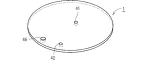
図9は電極ユニット蓋1の構造を示す斜視図である。同図に示すように、電極ユニット蓋1は電極ユニットベース2の表面形状に合致するように平面視して円状を呈しており、高圧導通穴41、接地導通穴42、及びガス中継穴46を有している。(Electrode unit lid 1)
FIG. 9 is a perspective view showing the structure of the
第1の貫通穴である高圧導通穴41は電極ユニット蓋1の中心領域を貫通して設けられ、第2の貫通穴である接地導通穴42とガス中継穴46とは電極ユニット蓋1の周辺付近にそれぞれ貫通して設けられる。
The high-voltage conduction hole 41, which is the first through hole, is provided so as to penetrate the central region of the
高圧導通穴41は高圧導通点P1との電気的接続用の穴であり、接地導通穴42は接地導通点P2との電気的接続用の穴であり、ガス中継穴46は電極ユニットベース2のガス通過溝24への原料ガス供給用の穴である。
The high-voltage conduction hole 41 is a hole for electrical connection with the high-voltage conduction point P1, the
電極ユニットベース2の表面上に電極ユニット蓋1を配置すると、ガス中継穴46の下方にガス通過溝24が位置するように設定されている。
When the
なお、高圧導通穴41、接地導通穴42、及びガス中継穴46に関し、電極ユニットベース2と電極ユニット蓋1との間にOリング等のガスシール材を設ける必要がないため、電極ユニット100(電極ユニット蓋1+電極ユニットベース2)の小型化を図ることができる。
Regarding the high-pressure conduction hole 41, the
(電極冷却板3)
図10は電極冷却板3の構造を示す斜視図である。同図に示すように、電極冷却板3は電極ユニットベース2及び冷却水マニホールド37の表面形状に合致するように、平面視して一部に凸部領域を有する略円状を呈している。電極冷却板3の凸部領域を除く円領域部分が電極ユニットベース2上に配置される。(Electrode cooling plate 3)
FIG. 10 is a perspective view showing the structure of the
さらに、電極冷却板3は高圧開口部61、接地導通溝62、冷却水供給溝63、冷却水入力穴64、冷却水出力穴65及びガス供給穴66を有している。
Further, the
高圧開口部61(開口部)は電極ユニットベース2の中心領域を貫通して設けられる。高圧開口部61は、電極ユニット蓋1上に電極冷却板3を配置した際、平面視して電極ユニット蓋1の高圧導通穴41全てを含み、高圧導通穴41より広い形状を有している。
The high-pressure opening 61 (opening) is provided so as to penetrate the central region of the
接地導通溝62は電極冷却板3の裏面側から貫通することなく設けられた溝であり、接地導通穴42を介した接地導通点P2との電気的接続用に設けられる。
The
冷却水供給溝63は、表面及び裏面に露出することなく電極冷却板3の内部に設けられた中空領域である。冷却水入力穴64から得られる冷却水は、冷却水の流れ68に沿って冷却水供給溝63内を流れる。冷却水供給溝63内を流れた冷却水は、最終的に冷却水出力穴65から出力される。
The cooling
冷却水入力穴64及び冷却水出力穴65は電極冷却板3の凸部領域に設けられる。電極冷却板3は、凸部領域が冷却水マニホールド37の表面上に位置するように配置される。
The cooling
なお、電極冷却板3は、片側に冷却水供給溝部分を形成した2つの板を、冷却水供給溝部分の形成面が対向するように、貼り合わせて形成することができる。貼り合わせ処理として、例えば熱拡散接合もしくは溶接が考えられる。上述した2つの板の貼り合わせ処理によって電極冷却板3に図10に示すような冷却水供給溝63を形成することができる。
The
(発生器ベースフランジ8及び冷却水マニホールド37)
図11は発生器ベースフランジ8の構造を示す斜視図である。同図に示すように、発生器ベースフランジ8は、平面視して、中心部に円状の開口部H8を有し、両端に第1及び第2の凸部領域を有する略円環状に形成される。(
FIG. 11 is a perspective view showing the structure of the
開口部H8の外周に沿って、発生器ベースフランジ8の内部に冷却水供給溝83が設けられる。冷却水供給溝83は摩擦攪拌接合(FSW:Friction Stir Welding)もしくは溶接による加工技術を用いて形成することができる。
A cooling
冷却水供給溝83は発生器ベースフランジ8内を冷却水が流れるための溝である。第2の凸部領域に設けられた冷却水入力穴84を介して供給される冷却水は、冷却水の流れ88Rに沿って冷却水供給溝83の一方円周側を流れる。
The cooling
その後、冷却水は、冷却水上昇の流れ89Uに沿って、第1の凸部領域に設けられた冷却水入力穴86から上部の冷却水マニホールド37に向けて出力される。
After that, the cooling water is output from the cooling
さらに、冷却水マニホールド37から得られる冷却水は、冷却水下降の流れ89Dに沿って第1の凸部領域に設けられた冷却水出力穴87に向けて流れる。
Further, the cooling water obtained from the cooling
その後、冷却水は、冷却水の流れ88Lに沿って冷却水供給溝83の他方円周側を流れる。そして、冷却水は第2の凸部領域に設けられた冷却水出力穴85から排出される。
After that, the cooling water flows along the other circumferential side of the cooling
図12は冷却水マニホールド37の構造を示す斜視図である。図13は電極冷却板3における冷却水の流れ68を拡大して示す説明図である。
FIG. 12 is a perspective view showing the structure of the cooling
図12に示すように、冷却水マニホールド37は平面視して発生器ベースフランジ8の第1の凸部領域(冷却水入力穴86及び冷却水出力穴87が形成される領域)に合致する形状を呈している。冷却水マニホールド37は各々が貫通する冷却水入力穴96及び冷却水出力穴97を有している。
As shown in FIG. 12, the cooling
図11〜図13それぞれの冷却水上昇の流れ89Uに沿って、下方の発生器ベースフランジ8の冷却水入力穴86を介して供給される冷却水は、冷却水マニホールド37の冷却水入力穴96介して上方の電極冷却板3に出力される。そして、電極冷却板3の冷却水入力穴64を介して供給される冷却水は、冷却水の流れ68に沿って冷却水供給溝63内を流れる。
11 to 13 The cooling water supplied through the cooling
その後、冷却水供給溝63を通過した冷却水は、冷却水下降の流れ89Dに沿って、冷却水マニホールド37の冷却水出力穴97及び発生器ベースフランジ8の冷却水出力穴87を介して発生器ベースフランジ8の冷却水供給溝83に出力される。
After that, the cooling water that has passed through the cooling
(組合せ構造)
図14は電極冷却板3、電極ユニット蓋1、電極ユニットベース2、冷却水マニホールド37及び発生器ベースフランジ8の組合せ構造を模式的に示す説明図である。図14にXYZ座標系を示している。(Combination structure)
FIG. 14 is an explanatory diagram schematically showing a combined structure of the
同図に示すように、電極冷却板3の冷却水入力穴64、冷却水マニホールド37の冷却水入力穴96、及び発生器ベースフランジ8の冷却水入力穴86が平面視して一致するように、発生器ベースフランジ8の第1の凸部領域上に、冷却水マニホールド37及び電極冷却板3の凸部領域が配置される。
As shown in the figure, the cooling
さらに、電極冷却板3の冷却水出力穴65、冷却水マニホールド37の冷却水出力穴97、及び発生器ベースフランジ8の冷却水出力穴87が平面視して一致するように、発生器ベースフランジ8の第1の凸部領域上に、冷却水マニホールド37及び電極冷却板3の凸部領域が配置される。
Further, the generator base flange is aligned so that the cooling
加えて、電極ユニット蓋1の高圧導通穴41と、電極ユニットベース2の高圧導通点P1とが平面視して一致するように、電極ユニットベース2の表面上に電極ユニット蓋1が配置される。さらに、平面視して高圧開口部61(開口部)が高圧導通穴41の全てを含むように、電極ユニット蓋1の表面上に電極冷却板3が配置される。
In addition, the
さらに、電極冷却板3の接地導通溝62、電極ユニット蓋1の接地導通穴42、及び、電極ユニットベース2の接地導通点P2が平面視して一致するように、電極ユニットベース2の表面上に電極ユニット蓋1が配置され、電極ユニット蓋1の表面上に電極冷却板3が配置される。
Further, on the surface of the
(原料ガスの供給)
上述した構造を有する本実施の形態の活性ガス生成装置10における原料ガスの供給系統について説明する。(Supply of raw material gas)
The supply system of the raw material gas in the
外部から、ガス供給フランジ39及び装置筐体30の一方側面に設けられた原料ガス供給経路33を介して、原料ガスが装置筐体30の収容空間SP30内に供給される。
From the outside, the raw material gas is supplied into the accommodation space SP30 of the
収容空間SP30内の原料ガスは、電極冷却板3のガス供給穴66及び電極ユニット蓋1のガス中継穴46を介して、電極ユニットベース2のガス通過溝24に供給される。
The raw material gas in the accommodation space SP30 is supplied to the
したがって、ガス供給穴66及びガス中継穴46から流入した原料ガスがガス通過溝24内を通過する。
Therefore, the raw material gas flowing in from the
(高圧電極11及び接地電極12の電気的接続)
電極ユニットベース2の高圧電極用溝21に埋め込まれる高圧電極11において、電極ユニットベース2の中心部の高圧導通点P1が電気的接続部位となる。(Electrical connection of
In the high-
活性ガス生成装置10において、電極ユニットベース2の第1の導通点である高圧導通点P1は、電極ユニット蓋1の高圧導通穴41、及び電極冷却板3の高圧開口部61を介して、高圧端子71と接続することが可能である。
In the
したがって、図1に示すように、装置筐体30の上部に設けられた高圧端子71と高圧電極11との電気的接続は、電極冷却板3の高圧開口部61及び電極ユニット蓋1の高圧導通穴41を介した、高圧端子71の電気的接続部位P71と高圧電極11の高圧導通点P1との電気的接続により、比較的簡単に行うことができる。
Therefore, as shown in FIG. 1, the electrical connection between the high-
この際、高圧開口部61(開口部)の開口領域は高圧導通穴41と比較して十分大きいため、電気的接続部位P71と高圧導通点P1との電気的接続を図る際、電気的接続部位P71が電極冷却板3と接触することはない。
At this time, since the opening region of the high-voltage opening 61 (opening) is sufficiently larger than the high-voltage conduction hole 41, the electrical connection portion is used when electrically connecting the electrical connection portion P71 and the high-voltage conduction point P1. P71 does not come into contact with the
一方、電極ユニットベース2の接地電極用溝22に埋め込まれる接地電極12において、電極ユニットベース2の周辺部付近の接地導通点P2が電気的接続部位となる。
On the other hand, in the
したがって、電極冷却板3と接地電極12との電気的接続は、電極ユニット蓋1の接地導通穴42を介して、電極ユニットベース2の接地導通点P2と電極冷却板3の接地導通溝62との電気的接続により、比較的簡単に行うことができる。
Therefore, the electrical connection between the
すなわち、図示しない接地導電部材を用いて、接地導通穴42を介して接地導通溝62と接地導通点P2とを接続することにより、比較的簡単に接地導通点P2を電極冷却板3に電気的に接続することができる。
That is, by connecting the
そして、導電性を有する電極冷却板3を接地レベルに設定することにより、同時に接地電極12を接地レベルに設定することができる。
Then, by setting the
電極押え板である電極冷却板3には、上方から図示しないバネ等の弾性部材により押圧力が付与される。したがって、電極冷却板3は上方から付与される押圧力によって、接地導電部材による接地導通点P2と接地導通溝62との電気的接続関係を良好に保つことができる。
A pressing force is applied to the
さらに、電極冷却板3は、上方から付与される押圧力で電極ユニット蓋1を安定性良く押さえることができる。
Further, the
(電極冷却板3による冷却機能)
以下、図1、図10〜図14を参照して、電極冷却板3による冷却機能を説明する。(Cooling function by electrode cooling plate 3)
Hereinafter, the cooling function by the
図1に示すように、発生器ベースフランジ8の上部に冷却水供給フランジ35が設けられる。冷却水供給フランジ35は取付用ネジ47を用いて発生器ベースフランジ8の表面上に取り付けられる。
As shown in FIG. 1, a cooling
したがって、外部から冷却水供給フランジ35を介して発生器ベースフランジ8内に冷却媒体である冷却水を供給することができる。
Therefore, the cooling water, which is a cooling medium, can be supplied from the outside into the
図1及び図11に示すように、平面視して冷却水供給フランジ35の給水経路に対応する位置に設けられた冷却水入力穴84から冷却水供給溝83内に冷却水が供給される。冷却水は冷却水の流れ88Rに沿って、冷却水供給溝83の一方円周側を流れ、冷却水の流れ89Uに沿って冷却水入力穴86から上方の冷却水マニホールド37に向けて出力される。
As shown in FIGS. 1 and 11, cooling water is supplied into the cooling
図1及び図12に示すように、冷却水は、冷却水上昇の流れ89Uに沿って、冷却水マニホールド37の冷却水入力穴96を介して上方の電極冷却板3に向けて流れる。
As shown in FIGS. 1 and 12, the cooling water flows along the cooling
図1、図10及び図13に示すように、冷却水入力穴64から得られた冷却水は冷却水の流れ68に沿って、円環状の冷却水供給溝63を流れ、最終的に冷却水出力穴65から排出される。冷却水が冷却水供給溝63を流れることにより、電極冷却板3は冷却機能を発揮することができる。
As shown in FIGS. 1, 10 and 13, the cooling water obtained from the cooling
冷却水供給溝63を流れた冷却水は冷却水出力穴65を介して下方の冷却水マニホールド37に向けて排出される。
The cooling water flowing through the cooling
その後、図1及び図12に示すように、冷却水は、冷却水下降の流れ89Dに沿って、冷却水マニホールド37の冷却水出力穴97を介して下方の発生器ベースフランジ8に向けて流れる。
After that, as shown in FIGS. 1 and 12, the cooling water flows along the cooling
そして、図1及び図11に示すように、発生器ベースフランジ8において、冷却水は、冷却水下降の流れ89Dに沿って冷却水出力穴87を介して冷却水供給溝83に供給される。その後、冷却水は、冷却水の流れ88Lに沿って冷却水供給溝83の他方円周側を流れる。そして、平面視して冷却水出力穴85に対応する領域に排水経路を有する図示しない冷却水排水フランジを介して外部に排出される。なお、冷却水排水フランジは冷却水供給フランジ35と同様に、発生器ベースフランジ8の表面上に設けられる。
Then, as shown in FIGS. 1 and 11, in the
その後、再び、外部から冷却水供給フランジ35を介して発生器ベースフランジ8内に冷却水を供給する。以下、上述したように、発生器ベースフランジ8、冷却水マニホールド37及び電極冷却板3内に冷却水を流すことにより、電極冷却板3の冷却水供給溝63に冷却水を循環させ、発生器ベースフランジ8の冷却水供給溝83に冷却水を循環させることができる。
After that, the cooling water is supplied from the outside into the
このように、電極冷却板3の冷却水供給溝63に冷却水を循環させることにより、電極冷却板3は電極ユニット蓋1を介して電極ユニットベース2を冷却する冷却機能を発揮することができる。
By circulating the cooling water through the cooling
さらに、発生器ベースフランジ8の冷却水供給溝83を冷却水が循環させることにより、発生器ベースフランジ8は電極ユニットベース2を冷却する冷却機能を発揮することができる。
Further, the cooling water circulates in the cooling
(効果)
本実施の形態の活性ガス生成装置10の電極ユニットベース2は、平面視して螺旋状に設けられガス内部流路となるガス通過溝24と、放電空間の下方にガス通過溝24に連通して設けられる複数のガス噴出口6(少なくとも一つのガス噴出口)とを含んでいる。(effect)
The
したがって、本実施の形態の活性ガス生成装置10は、複数のガス噴出口6と放電空間との間に、誘電体バリア放電に関与しない非放電空間が形成されないため、活性ガスが失活する現象を効果的に抑制する効果を奏する。
Therefore, in the
さらに、電極ユニットベース2に、複数のガス噴出口6、高圧電極11、接地電極12及びガス通過溝24を設け、電極ユニット蓋1に高圧導通穴41、接地導通穴42及びガス中継穴46を設け、電極冷却板3に高圧開口部61、接地導通溝62及びガス供給穴66等を設けるという比較的簡単な構成で上記効果を発揮することがきる。このため、活性ガス生成装置10の装置構成の簡略化を図ることができる。
Further, the
加えて、活性ガス生成装置10において、ガス通過溝24は平面視して螺旋状に設けられている。このため、電極ユニットベース2自体の面積を大きくすることなく、複数のガス噴出口6からガス濃度が飽和した状態で活性ガスを噴出することができる分、装置の小型化を図ることができる。
In addition, in the
さらに、活性ガス生成装置10における電極ユニット蓋1は、平面視して高圧導通点P1及び接地導通点P2に合致する領域に設けられ、各々が貫通する高圧導通穴41及び接地導通穴42を有している。
Further, the
このため、電極ユニット蓋1は、高圧導通穴41及び接地導通穴42を介した高圧導通点P1及び接地導通点P2と外部との電気的接続機能を確保しつつ、電極ユニットベース2の上方を塞ぐことができる。
Therefore, the
さらに、電極押え板である電極冷却板3は、電極ユニット蓋1上に電極冷却板3を配置した際、平面視して電極ユニット蓋1の高圧導通穴41を含み、高圧導通穴41より広い形状の開口部である高圧開口部61を有している。
Further, the
このため、電極冷却板3は、高圧導通穴41を介した高圧導通点P1と外部の高圧端子71との電気的接続機能を確保し、接地導通穴42を介して接地導通点P2と自身との電気的接続を図ることができる。
Therefore, the
さらに、上方から付与される押圧力で電極ユニット蓋1を押圧する電極冷却板3は、電極ユニット蓋1を安定性良く押さえることができる。
Further, the
加えて、本実施の形態の活性ガス生成装置10では、電極ユニット100内において、高圧電極11及び接地電極12に関し、平面視して電極ユニットベース2の最外周に接地電極12が位置するように配置されている。
In addition, in the
このため、高電圧が印加される高圧電極11から電極ユニットベース2の外周部に向かう電界ベクトルを、高圧電極11より外周に存在する接地電極12によって必ず吸収することができる。
Therefore, the electric field vector from the high-
さらに、活性ガス生成装置10は、電極冷却板3の上述した冷却機能により、電極ユニット蓋1を介して電極ユニットベース2を冷却して、電極ユニットベース2の熱除去を行うことができる。
Further, the active
加えて、本実施の形態の活性ガス生成装置10は、取付用ネジ48によって、電極冷却板3、電極ユニット蓋1、電極ユニットベース2、及び冷却媒体循環機構(冷却水マニホールド37+発生器ベースフランジ8)は一体的に連結されるため、活性ガス生成装置10の小型化を図ることができる。
In addition, in the
この発明は詳細に説明されたが、上記した説明は、すべての局面において、例示であって、この発明がそれに限定されるものではない。例示されていない無数の変形例が、この発明の範囲から外れることなく想定され得るものと解される。 Although the present invention has been described in detail, the above description is exemplary in all aspects and the invention is not limited thereto. It is understood that innumerable variations not illustrated can be assumed without departing from the scope of the present invention.
1 電極ユニット蓋
2 電極ユニットベース
3 電極冷却板
6 ガス噴出口
8 発生器ベースフランジ
10 活性ガス生成装置
11 高圧電極
12 接地電極
21 高圧電極用溝
22 接地電極用溝
24 ガス通過溝
30 装置筐体
37 冷却水マニホールド
41 高圧導通穴
42 接地導通穴
46 ガス中継穴
61 高圧開口部
62 接地導通溝
63,83 冷却水供給溝
66 ガス供給穴
71 高圧端子
P1 高圧導通点
P2 接地導通点1
Claims (5)
第1の電極(11)及び第2の電極(12)を有し、外部より交流電圧を受ける電極ユニットベース(2)と、
前記電極ユニットベースの表面上に設けられる電極ユニット蓋(1)と、
前記電極ユニット蓋の表面上に設けられ、上方から付与される押圧力で電極ユニット蓋を押圧する電極押え板(3)と、
前記電極ユニットベース、前記電極ユニット蓋及び前記電極押え板を収容する装置筐体(30)とを備え、
前記電極ユニットベースは、
表面から所定の形成深さで設けられる第1及び第2の電極用溝(21,22)と、
前記第1及び第2の電極用溝に埋め込まれて設けられ、各々が導電性を有する前記第1及び第2の電極と、
前記電極ユニットベース内に形成され、原料ガスが通過するガス内部流路(24)とを含み、前記ガス内部流路は平面視して螺旋状に設けられ、前記第1及び第2の電極は前記ガス内部流路と共に平面視して螺旋状に設けられ、
前記第1及び第2の電極は端部に第1及び第2の導通点(P11,P12)を有し、
前記第1及び第2の電極は、前記電極ユニットベースの一部及び前記ガス内部流路を挟んで互いに対向するように、前記ガス内部流路の両側に配置され、前記第1及び第2の電極間における前記ガス内部流路内の領域が前記放電空間となり、前記交流電圧を受けることにより前記放電空間に誘電体バリア放電が発生され、
前記電極ユニットベースは、裏面に設けられる少なくとも一つのガス噴出口(6)をさらに含み、前記少なくとも一つのガス噴出口は前記放電空間の下方に前記ガス内部流路に連通して設けられ、前記放電空間に供給された原料ガスを活性化して得られる活性ガスが、前記少なくとも一つのガス噴出口から噴出され、
前記電極ユニット蓋は、前記電極ユニットベースの前記ガス内部流路に繋がるように設けられるガス中継穴(46)と、平面視して前記第1及び第2の導通点に合致する領域に設けられる第1及び第2の貫通穴(41,42)とを有し、前記ガス中継穴、前記第1及び第2の貫通穴は前記電極ユニット蓋を貫通し、
前記電極押え板は、平面視して前記第1の貫通穴を含み前記第1の貫通穴より広い形状の開口部(61)と、平面視して前記ガス中継穴と合致する領域に設けられるガス供給穴(66)とを有し、前記第2の貫通穴を介して前記第2の導通点と電気的に接続される、
活性ガス生成装置。 An active gas generator (10) that activates a raw material gas supplied to a discharge space where a dielectric barrier discharge is generated to generate an active gas.
An electrode unit base (2) having a first electrode (11) and a second electrode (12) and receiving an AC voltage from the outside,
An electrode unit lid (1) provided on the surface of the electrode unit base and
An electrode pressing plate (3) provided on the surface of the electrode unit lid and pressing the electrode unit lid with a pressing force applied from above, and an electrode pressing plate (3).
A device housing (30) for accommodating the electrode unit base, the electrode unit lid, and the electrode holding plate is provided.
The electrode unit base is
The first and second electrode grooves (21, 22) provided at a predetermined formation depth from the surface, and
The first and second electrodes, which are embedded in the first and second electrode grooves and each have conductivity,
The first and second electrodes are formed in the electrode unit base and include a gas internal flow path (24) through which the raw material gas passes, and the gas internal flow path is spirally provided in a plan view. It is provided spirally together with the gas internal flow path in a plan view.
The first and second electrodes have first and second conduction points (P11, P12) at the ends.
The first and second electrodes are arranged on both sides of the gas internal flow path so as to face each other with a part of the electrode unit base and the gas internal flow path interposed therebetween. The region in the gas internal flow path between the electrodes becomes the discharge space, and by receiving the AC voltage, a dielectric barrier discharge is generated in the discharge space.
The electrode unit base further comprises at least one gas jet port (6) provided on a rear surface, said at least one gas orifice is communicated provided et al is to the gas internal channel below the discharge space, The active gas obtained by activating the raw material gas supplied to the discharge space is ejected from the at least one gas outlet.
The electrode unit lid is provided in a gas relay hole (46) provided so as to be connected to the gas internal flow path of the electrode unit base and a region corresponding to the first and second conduction points in a plan view. It has first and second through holes (41, 42), and the gas relay hole and the first and second through holes penetrate the electrode unit lid.
The electrode holding plate is provided in an opening (61) having a shape wider than the first through hole including the first through hole in a plan view and a region corresponding to the gas relay hole in a plan view. It has a gas supply hole (66) and is electrically connected to the second conduction point through the second through hole.
Inert gas generator.
前記第2の電極が接地レベルに設定され、前記第1の電極に前記交流電圧が印加され、
前記第1及び第2の電極は、平面視して前記電極ユニットベースの最外周に前記第2の電極が位置するように、配置されることを特徴とする、
活性ガス生成装置。 The active gas generator according to claim 1.
The second electrode is set to the ground level, and the AC voltage is applied to the first electrode.
The first and second electrodes are arranged so that the second electrode is located on the outermost circumference of the electrode unit base in a plan view.
Inert gas generator.
前記電極ユニットベースを裏面側から支持し、かつ、前記電極押え板に冷却媒体を循環させる冷却媒体循環機構(8,37)をさらに備え、
前記電極押え板は前記電極ユニット蓋側から前記電極ユニットベースを冷却する冷却機能を有する、
活性ガス生成装置。 The active gas generator according to claim 2.
A cooling medium circulation mechanism (8, 37) for supporting the electrode unit base from the back surface side and circulating the cooling medium on the electrode holding plate is further provided.
The electrode holding plate has a cooling function of cooling the electrode unit base from the electrode unit lid side.
Inert gas generator.
前記電極ユニットベース、前記電極ユニット蓋、前記電極押え板、及び前記冷却媒体循環機構は一体的に連結される、
活性ガス生成装置。 The active gas generator according to claim 3.
The electrode unit base, the electrode unit lid, the electrode holding plate, and the cooling medium circulation mechanism are integrally connected.
Inert gas generator.
前記装置筐体の上部に取り付けられ、前記交流電圧を供給する交流電圧供給端子(71)をさらに備え、
前記交流電圧供給端子は前記開口部及び前記第1の貫通穴を介して前記第1の導通点に電気的に接続される、
活性ガス生成装置。 The active gas generator according to any one of claims 2 to 4.
Further provided with an AC voltage supply terminal (71) attached to the upper part of the apparatus housing and supplying the AC voltage.
The AC voltage supply terminal is electrically connected to the first conduction point through the opening and the first through hole.
Inert gas generator.
Applications Claiming Priority (1)
| Application Number | Priority Date | Filing Date | Title |
|---|---|---|---|
| PCT/JP2019/005025 WO2020165964A1 (en) | 2019-02-13 | 2019-02-13 | Activated-gas generation device |
Publications (2)
| Publication Number | Publication Date |
|---|---|
| JPWO2020165964A1 JPWO2020165964A1 (en) | 2021-03-11 |
| JP6844937B2 true JP6844937B2 (en) | 2021-03-17 |
Family
ID=71944668
Family Applications (1)
| Application Number | Title | Priority Date | Filing Date |
|---|---|---|---|
| JP2019541211A Active JP6844937B2 (en) | 2019-02-13 | 2019-02-13 | Inert gas generator |
Country Status (7)
| Country | Link |
|---|---|
| US (1) | US11129267B2 (en) |
| JP (1) | JP6844937B2 (en) |
| KR (1) | KR102394132B1 (en) |
| CN (1) | CN111836916B (en) |
| DE (1) | DE112019000174B4 (en) |
| TW (1) | TWI697581B (en) |
| WO (1) | WO2020165964A1 (en) |
Families Citing this family (7)
| Publication number | Priority date | Publication date | Assignee | Title |
|---|---|---|---|---|
| US11532458B2 (en) * | 2018-05-30 | 2022-12-20 | Toshiba Mitsubishi-Electric Industrial Systems Corporation | Active gas generation apparatus |
| CN113170567B (en) | 2019-11-12 | 2023-11-28 | 东芝三菱电机产业系统株式会社 | Active gas generating device |
| US11839014B2 (en) * | 2019-11-27 | 2023-12-05 | Toshiba Mitsubishi-Electric Industrial Systems Corporation | Active gas generating apparatus |
| CN114916255B (en) * | 2020-12-07 | 2025-09-23 | 株式会社Tmeic | Active gas generating device |
| CN114982382B (en) * | 2020-12-24 | 2025-09-19 | 株式会社Tmeic | Active gas generating device |
| CN113747646B (en) * | 2021-08-12 | 2023-06-27 | 西安交通大学 | Double-spiral curled microcavity plasma device structure and preparation method thereof |
| EP4340548B1 (en) * | 2022-05-18 | 2025-10-15 | TMEIC Corporation | Active-gas-generating apparatus |
Family Cites Families (24)
| Publication number | Priority date | Publication date | Assignee | Title |
|---|---|---|---|---|
| JPS5139811A (en) | 1974-09-30 | 1976-04-03 | Senyo Kiko Kk | Norikagokurumanado no futenseigyosochi |
| JP2537304B2 (en) | 1989-12-07 | 1996-09-25 | 新技術事業団 | Atmospheric pressure plasma reaction method and apparatus |
| JP2537304Y2 (en) | 1992-08-24 | 1997-05-28 | 富士車輌株式会社 | Carbon treatment equipment in dry cleaning machines |
| JPH11144891A (en) * | 1997-11-07 | 1999-05-28 | Toshiba Corp | Plasma processing equipment |
| US6354903B1 (en) * | 1999-06-29 | 2002-03-12 | Delphi Technologies, Inc. | Method of manufacture of a plasma reactor with curved shape for treating auto emissions |
| JP2001053065A (en) * | 1999-08-13 | 2001-02-23 | Nec Kyushu Ltd | Plasma processing apparatus |
| JP4658298B2 (en) * | 2000-09-11 | 2011-03-23 | 中部電力株式会社 | Ozone generator |
| JP4402860B2 (en) * | 2001-03-28 | 2010-01-20 | 忠弘 大見 | Plasma processing equipment |
| US7727487B2 (en) * | 2003-02-12 | 2010-06-01 | Ngk Insulators, Ltd. | Plasma reaction vessel, and method of producing the same |
| US7063819B2 (en) * | 2003-03-21 | 2006-06-20 | The Regents Of The University Of California | Nonthermal plasma processor utilizing additive-gas injection and/or gas extraction |
| US20080124254A1 (en) * | 2006-05-22 | 2008-05-29 | Dae-Kyu Choi | Inductively Coupled Plasma Reactor |
| KR100864111B1 (en) * | 2006-05-22 | 2008-10-16 | 최대규 | Inductively coupled plasma reactor |
| JP5088667B2 (en) * | 2007-03-06 | 2012-12-05 | セイコーエプソン株式会社 | Plasma processing equipment |
| US20080314734A1 (en) * | 2007-06-21 | 2008-12-25 | The Regents Of The University Of California | Carbonaceous solid fuel gasifier utilizing dielectric barrier non-thermal plasma |
| US8857371B2 (en) * | 2007-08-31 | 2014-10-14 | Toshiba Mitsubishi-Electric Industrial Systems Corporation | Apparatus for generating dielectric barrier discharge gas |
| JP5423205B2 (en) * | 2008-08-29 | 2014-02-19 | 東京エレクトロン株式会社 | Deposition equipment |
| JP5490585B2 (en) * | 2009-05-29 | 2014-05-14 | 株式会社日立国際電気 | Substrate processing apparatus, substrate processing method, and semiconductor device manufacturing method |
| JP5328685B2 (en) | 2010-01-28 | 2013-10-30 | 三菱電機株式会社 | Plasma processing apparatus and plasma processing method |
| DE102011105713B4 (en) * | 2011-06-23 | 2014-06-05 | Cinogy Gmbh | Electrode arrangement for a dielectrically impeded gas discharge |
| WO2013035375A1 (en) * | 2011-09-09 | 2013-03-14 | 東芝三菱電機産業システム株式会社 | Plasma generator and cvd device |
| US9497846B2 (en) * | 2013-10-24 | 2016-11-15 | The United States Of America As Represented By The Administrator Of The National Aeronautics And Space Administration | Plasma generator using spiral conductors |
| JP6618772B2 (en) * | 2015-11-06 | 2019-12-11 | エア・ウォーター株式会社 | Atmospheric pressure plasma processing equipment |
| JP2017091709A (en) * | 2015-11-06 | 2017-05-25 | エア・ウォーター株式会社 | Ambient air pressure plasma processing apparatus |
| US9934942B1 (en) * | 2016-10-04 | 2018-04-03 | Applied Materials, Inc. | Chamber with flow-through source |
-
2019
- 2019-02-13 JP JP2019541211A patent/JP6844937B2/en active Active
- 2019-02-13 US US16/619,269 patent/US11129267B2/en active Active
- 2019-02-13 KR KR1020207025577A patent/KR102394132B1/en active Active
- 2019-02-13 CN CN201980014601.9A patent/CN111836916B/en active Active
- 2019-02-13 DE DE112019000174.4T patent/DE112019000174B4/en active Active
- 2019-02-13 WO PCT/JP2019/005025 patent/WO2020165964A1/en not_active Ceased
- 2019-06-21 TW TW108121757A patent/TWI697581B/en active
Also Published As
| Publication number | Publication date |
|---|---|
| DE112019000174B4 (en) | 2024-02-01 |
| JPWO2020165964A1 (en) | 2021-03-11 |
| TW202030358A (en) | 2020-08-16 |
| TWI697581B (en) | 2020-07-01 |
| CN111836916A (en) | 2020-10-27 |
| KR102394132B1 (en) | 2022-05-04 |
| CN111836916B (en) | 2022-06-14 |
| KR20200116989A (en) | 2020-10-13 |
| US11129267B2 (en) | 2021-09-21 |
| DE112019000174T5 (en) | 2021-04-22 |
| US20200260565A1 (en) | 2020-08-13 |
| WO2020165964A1 (en) | 2020-08-20 |
Similar Documents
| Publication | Publication Date | Title |
|---|---|---|
| JP6844937B2 (en) | Inert gas generator | |
| JP7489454B2 (en) | Integrated electrode and ground plane for substrate support - Patents.com | |
| JP5248370B2 (en) | Shower head and plasma processing apparatus | |
| US11309167B2 (en) | Active gas generation apparatus and deposition processing apparatus | |
| TWI803076B (en) | Active gas generation apparatus | |
| WO2019049230A1 (en) | Active gas generating device | |
| CN114982382A (en) | Active gas generating device | |
| WO2024084640A1 (en) | Active gas generation device | |
| TWI847337B (en) | Active gas generation apparatus | |
| JP7493905B1 (en) | Active Gas Generator | |
| JP2017091709A (en) | Ambient air pressure plasma processing apparatus | |
| WO2023120245A1 (en) | Substrate support and plasma processing apparatus | |
| KR20260027328A (en) | Wafer loading platform | |
| KR20210026874A (en) | A apparatus for reacing plasma at atm | |
| KR20100079327A (en) | Atmospheric pressure plasma generating device and atmospheric pressure plasma device for treating the surface having the same |
Legal Events
| Date | Code | Title | Description |
|---|---|---|---|
| A621 | Written request for application examination |
Free format text: JAPANESE INTERMEDIATE CODE: A621 Effective date: 20190729 |
|
| A131 | Notification of reasons for refusal |
Free format text: JAPANESE INTERMEDIATE CODE: A131 Effective date: 20200818 |
|
| A521 | Request for written amendment filed |
Free format text: JAPANESE INTERMEDIATE CODE: A523 Effective date: 20200918 |
|
| TRDD | Decision of grant or rejection written | ||
| A01 | Written decision to grant a patent or to grant a registration (utility model) |
Free format text: JAPANESE INTERMEDIATE CODE: A01 Effective date: 20210224 |
|
| A61 | First payment of annual fees (during grant procedure) |
Free format text: JAPANESE INTERMEDIATE CODE: A61 Effective date: 20210224 |
|
| R150 | Certificate of patent or registration of utility model |
Ref document number: 6844937 Country of ref document: JP Free format text: JAPANESE INTERMEDIATE CODE: R150 |
|
| R250 | Receipt of annual fees |
Free format text: JAPANESE INTERMEDIATE CODE: R250 |
|
| R250 | Receipt of annual fees |
Free format text: JAPANESE INTERMEDIATE CODE: R250 |
|
| R250 | Receipt of annual fees |
Free format text: JAPANESE INTERMEDIATE CODE: R250 |