JP6848314B2 - Stator core and rotary electric machine - Google Patents
Stator core and rotary electric machine Download PDFInfo
- Publication number
- JP6848314B2 JP6848314B2 JP2016195969A JP2016195969A JP6848314B2 JP 6848314 B2 JP6848314 B2 JP 6848314B2 JP 2016195969 A JP2016195969 A JP 2016195969A JP 2016195969 A JP2016195969 A JP 2016195969A JP 6848314 B2 JP6848314 B2 JP 6848314B2
- Authority
- JP
- Japan
- Prior art keywords
- stator core
- holes
- portions
- caulking
- hole
- Prior art date
- Legal status (The legal status is an assumption and is not a legal conclusion. Google has not performed a legal analysis and makes no representation as to the accuracy of the status listed.)
- Active
Links
Images


Landscapes
- Manufacture Of Motors, Generators (AREA)
- Iron Core Of Rotating Electric Machines (AREA)
Description
本発明は、ステータコアおよび回転電機に関し、特に、複数の磁性体板を積層してステータコアを構成するために用いて好適なものである。 The present invention relates to a stator core and a rotary electric machine, and is particularly suitable for use in laminating a plurality of magnetic material plates to form a stator core.
回転電機は、ロータ(回転子)とステータ(固定子)とを有する。ステータは、ステータコアと巻線を有する。ステータコアは、周方向に延在する環状のヨーク部(コアバック部)と、ヨーク部の内周面から軸芯に向かう方向に延在し、周方向に間隔を有して配置される複数のティース部とを有する。このようなステータコアは、電磁鋼板等の磁性体板が積層されて構成される。また、磁性体板の板面は、絶縁物(絶縁被膜)でコーティングされている。 The rotary electric machine has a rotor (rotor) and a stator (stator). The stator has a stator core and windings. The stator core has an annular yoke portion (core back portion) extending in the circumferential direction and a plurality of stator cores extending in the direction from the inner peripheral surface of the yoke portion toward the axis and arranged at intervals in the circumferential direction. It has a teeth part. Such a stator core is formed by laminating magnetic steel plates such as electrical steel sheets. The surface of the magnetic plate is coated with an insulator (insulating film).
ステータコアを形成する際には、ステータコアの形状に合わせて打ち抜き加工された複数の磁性体板を積層する。積層された複数の磁性体板は、かしめや溶接によって固定(連結)される。このようなかしめや溶接の加工が施されると、かしめや溶接が行われた箇所において、磁性体の板面に形成されている絶縁物のコーティングが剥がれる場合がある。この場合、磁性体間が電気的に導通し、いわゆる層間短絡が生じる。ステータコアの2箇所以上で層間短絡が生じると、ステータコアに渦電流が流れ、この渦電流に基づくジュール損(渦電流損)によりステータコアの損失が増大する。その結果、回転電機の出力効率が低下する虞がある。 When forming the stator core, a plurality of magnetic material plates punched according to the shape of the stator core are laminated. The plurality of laminated magnetic plates are fixed (connected) by caulking or welding. When such caulking or welding is performed, the coating of the insulating material formed on the plate surface of the magnetic material may be peeled off at the place where the caulking or welding is performed. In this case, the magnetic materials are electrically conductive, and a so-called interlayer short circuit occurs. When an interlayer short circuit occurs at two or more points of the stator core, an eddy current flows through the stator core, and the Joule loss (eddy current loss) based on the eddy current increases the loss of the stator core. As a result, the output efficiency of the rotary electric machine may decrease.
特許文献1には、積層した複数の磁性体板に形成されるかしめの、コアバック部の周方向の位置を、積層方向において、交互に複数回切り替えることが開示されている。また、特許文献1には、切り替え位置に配置された磁性体板に、かしめにより出来る突起が挿入される孔部を形成することが開示されている。さらに、特許文献1には、コアバック部の周方向において、かしめと孔部との間に、コアバック部の外周からティース部に向かって延在するスリットを形成することが開示されている。特許文献1の記載によれば、以上のようにして、層間短絡によりステータコアに流れる渦電流の経路を長くすることにより、ステータコアの渦電流損を低減することができるとされている。
しかしながら、特許文献1に記載の技術では、渦電流の経路が極端に長くなる。このため、ステータコアの内部の磁束の分布に極端な偏りが生じる虞がある。従って、ステータコアのトータルの損失を低減することができない虞がある。また、かしめの位置が異なる磁性体板や、孔部およびスリットを形成した磁性体板を作製しなければならない。即ち、複数種類の磁性体板を作製する必要がある。従って、ステータコアの製造工程が増大する虞がある。さらに、かしめにより出来る突起部を孔部に挿入する。このため、突起部を孔部に挿入する部分では、通常のかしめよりも固定力が弱くなる虞がある。
本発明は、以上の問題点に鑑みてなされたものであり、ステータコアの層間短絡による渦電流損を簡単な構成で低減し、回転電機の出力効率が低下することを抑制することができるようにすることを目的とする。
However, in the technique described in
The present invention has been made in view of the above problems, and it is possible to reduce the eddy current loss due to the interlayer short circuit of the stator core with a simple configuration and suppress the decrease in the output efficiency of the rotary electric machine. The purpose is to do.
本発明のステータコアは、周方向に延在する環状のヨーク部と、前記ヨーク部の内周面から軸芯に向かう方向に延在し、前記周方向において相互に間隔を有して配置された複数のティース部と、を有するステータコアであって、前記ヨーク部と前記複数のティース部は、板面が相互に平行になるように積層された複数の磁性体板を有し、前記複数の磁性体板は、当該複数の磁性体板を相互に連結する複数の連結部を有し、前記磁性体板の領域に高抵抗領域を有し、前記高抵抗領域の電気抵抗率は、前記磁性体板の電気抵抗率よりも高く、前記高抵抗領域は、前記ステータコアの軸に沿う方向の一方の端面から他方の端面まで存在する領域であり、前記複数の連結部は、前記ヨーク部に形成された連結部と、前記ティース部に形成された連結部とを含み、前記高抵抗領域は、少なくとも、前記ヨーク部に形成された連結部と、前記ティース部に形成された連結部との間に形成されていることを特徴とする。 The stator core of the present invention has an annular yoke portion extending in the circumferential direction and an annular yoke portion extending in the direction from the inner peripheral surface of the yoke portion toward the axial core, and is arranged at a distance from each other in the circumferential direction. A stator core having a plurality of teeth portions, wherein the yoke portion and the plurality of teeth portions have a plurality of magnetic material plates laminated so that the plate surfaces are parallel to each other, and the plurality of magnetic plates are provided. body plate has a plurality of coupling portion coupling the plurality of magnetic plates to each other, have a high resistance region in the realm of the magnetic plate, the electrical resistivity of the high resistance region, the magnetic higher than the electrical resistivity of the body plate, the high resistance region, Ri region der present from one end face of the direction along the axis of the stator core to the other end face, the plurality of connecting portions, the yoke portion The high resistance region includes at least the connecting portion formed in the yoke portion and the connecting portion formed in the teeth portion, including the formed connecting portion and the connecting portion formed in the teeth portion. characterized that you have formed between.
本発明によれば、ステータコアの層間短絡による渦電流損を簡単な構成で低減し、回転電機の出力効率が低下することを抑制することができる。 According to the present invention, it is possible to reduce the eddy current loss due to the interlayer short circuit of the stator core with a simple configuration and suppress the decrease in the output efficiency of the rotary electric machine.
以下、図面を参照しながら、本発明の実施形態を説明する。尚、各図では、説明の都合上、説明に必要でない部分の図示を省略すると共に、図示した部分の構成を簡略化している。
(第1の実施形態)
まず、第1の実施形態を説明する。
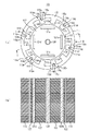
図1は、本実施形態の回転電機の構成の一例を示す図である。図1(a)は、回転電機100を回転軸130の延設方向に沿って見た図である。図1(b)は、図1(a)のI−I断面図である。尚、回転電機100は、電動機であっても発電機であってもよい。
Hereinafter, embodiments of the present invention will be described with reference to the drawings. In each figure, for convenience of explanation, illustration of parts not necessary for explanation is omitted, and the configuration of the illustrated parts is simplified.
(First Embodiment)
First, the first embodiment will be described.
FIG. 1 is a diagram showing an example of the configuration of the rotary electric machine of the present embodiment. FIG. 1A is a view of the rotary
回転電機100は、ステータ110と、ロータ120とを有する。
図1に示す例では、ロータ120は、4個のマグネット121a〜121dと、回転電機100の軸方向において積層された複数の電磁鋼板122とを有しており、マグネット121a〜121dは、回転電機100の周方向において90度間隔で配置されている。尚、ロータは、図1に示す構成のものに限定されず、公知の種々の構造のものを採用することができるので、ここでは、その詳細な説明を省略する。
The rotary
In the example shown in FIG. 1, the
ステータ110は、ステータコア111と図示しない巻線およびケースを有する。ステータコア111は、その軸芯が回転軸130の軸芯と略一致するように配置される。ステータコア111は、ヨーク部(コアバック部)112と、複数のティース部113a〜113lとを有する。ヨーク部112は、回転電機100の周方向に延在する環状の部分である。複数のティース部113a〜113lは、それぞれヨーク部112の内周面から軸芯に向かう方向(回転軸130がある方向)に延在する部分である。複数のティース部113a〜113lは、回転電機100の周方向において相互に間隔を有して配置される。尚、図1では図示を省略しているが、複数のティース部113a〜113lには、集中巻きによる巻線が施されている。尚、複数のティース部113a〜113lに施される巻線は、集中巻きによるものに限定されず、分布巻きによるものであってもよい。また、図1では図示を省略しているが、回転電機100は、ケースを有する。ケースの内周面とステータコア111の外周面とが相互に対向するようにケースを配置し、ステータコア111とケースとの嵌め合い加工(例えば焼嵌め)が施される。尚、以下の説明では、回転電機100の周方向を必要に応じて周方向と略称し、回転電機100の径方向を必要に応じて径方向と略称し、回転軸130の延設方向(軸に沿う方向)を必要に応じて軸方向と称する。
The
図1(b)に示すように、ステータコア111は、複数の磁性体板を用いて構成される。複数の磁性体板は、軸方向に沿って、板面が相互に平行になるように積層される。磁性体板の板面には、絶縁物のコーティング(絶縁被膜)が施されている。本実施形態では、磁性体板が、電磁鋼板である場合を例に挙げて説明する。図1(a)に示すように、ステータコア111には、孔114a〜114lが形成されている。ヨーク部112、複数のティース部113a〜113l、および孔114a〜114lの形状に合うように、母材(電磁鋼板)に対して打ち抜き加工を施すことにより、ステータコア111を構成する電磁鋼板が形成される。本実施形態では、ステータコア111を構成する電磁鋼板は、いずれも同じ形状および大きさを有する場合を例に挙げて説明する。
As shown in FIG. 1 (b), the
このようにして得られた複数の電磁鋼板を、ヨーク部112、ティース部113a〜113l、および孔114a〜114lに対応する位置がそれぞれ合うように積層した状態で、かしめる。このようにして複数の電磁鋼板をかしめることにより、孔114a〜114lは、複数の電磁鋼板の積層方向(軸方向)においてステータコア111を貫通する。
The plurality of electrical steel sheets thus obtained are crimped in a state of being laminated so that the positions corresponding to the
また、複数の電磁鋼板をかしめることにより、複数の電磁鋼板は相互に連結される。電磁鋼板をかしめることにより、電磁鋼板の一方の面には突起部が他方の面には窪み部が表裏一体となって形成される。電磁鋼板の突起部と当該電磁鋼板に隣接する電磁鋼板の窪み部とが嵌合することにより、複数の電磁鋼板は相互に連結される。以下の説明では、かしめにより板面にできる突起部および窪み部を、必要に応じて、カシメ部と称する。カシメ部は、複数の電磁鋼板を機械的に連結する連結部の一例である。尚、カシメ部の数、位置、および形状は、複数の電磁鋼板を連結することができれば、特に限定されない。本実施形態では、図1(a)に示すように、カシメ部115a〜115rが形成される場合を例に挙げて示す。
Further, by crimping the plurality of electromagnetic steel sheets, the plurality of electromagnetic steel sheets are connected to each other. By crimping the electrical steel sheet, a protrusion is formed on one surface of the electrical steel sheet, and a recess is formed on the other surface so that the front and back surfaces are integrated. By fitting the protrusions of the electrical steel sheet and the recesses of the electrical steel sheet adjacent to the electrical steel sheet, the plurality of electrical steel sheets are connected to each other. In the following description, the protrusions and recesses formed on the plate surface by caulking will be referred to as caulking portions, if necessary. The caulking portion is an example of a connecting portion that mechanically connects a plurality of electromagnetic steel plates. The number, position, and shape of the crimped portion are not particularly limited as long as a plurality of electromagnetic steel plates can be connected. In the present embodiment, as shown in FIG. 1A, a case where the caulked
ここで、孔114a〜114lを形成するに至った経緯について説明する。
図2は、ステータコアの周方向の一部分(約30[°]分)を示す図である。図2は、図1(a)のうち、ティース部113a付近の領域に対応する図である。ただし、図2に示すステータコアは、図1(a)に示したステータコア111に形成されている孔114a〜114lが形成されていない。図2に示すステータコアのその他の構成は、図1(a)に示したステータコア111の構成と同じである。以下の説明は、このようなステータコア(孔114a〜114lが形成されていないステータコア)を、必要に応じて通常のステータコアと称する。
Here, the process leading to the formation of the
FIG. 2 is a diagram showing a part (about 30 [°] minutes) of the stator core in the circumferential direction. FIG. 2 is a diagram corresponding to a region in the vicinity of the
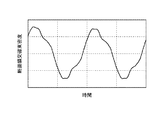
本発明者らは、カシメ部115a〜115cで層間短絡が生じた際の損失を算出することとした。そこでまず、通常のステータコアの内部の磁束密度と、カシメ部115a〜115cとの関係について調査した。具体的に、図2において、カシメ部115a、115bの重心の位置を相互に結ぶ仮想線210aを、軸方向に沿うように切ることにより得られる断面を鎖交する磁束密度のうち、当該断面に直交する磁束(図2の白抜き矢印線を参照)の磁束密度(以下、「第1の断面鎖交磁束密度」と称する)と時間との関係を数値解析で求めた。同様に、カシメ部115a、115cの重心の位置を相互に結ぶ仮想線210bを、軸方向に沿うように切った断面を鎖交する磁束密度のうち、当該断面に直交する磁束(図2の白抜き矢印線を参照)の磁束密度(以下、「第2の断面鎖交磁束密度」と称する)と時間との関係を数値解析で求めた。図3に、その結果を示す。尚、カシメ部の重心の位置は、電磁鋼板の板面に対して垂直な方向に沿ってカシメ部を見たとき(即ち、カシメ部を平面視したとき)のカシメ部の領域の輪郭を縁とする平面の重心の位置を指す(このことは、他の説明においても同じである)。ここで、カシメ部115b、115cは、カシメ部115aの重心の位置と回転電機100の軸芯の位置とを通る直線を軸とする軸対称の位置にある。従って、理論上、第1の断面鎖交磁束密度と時間との関係と、第2の断面鎖交磁束密度と時間との関係は、同じになる。そこで、以下の説明では、第1の断面鎖交磁束密度と第2の断面鎖交磁束密度を断面鎖交磁束密度と総称する。
The present inventors have decided to calculate the loss when an interlayer short circuit occurs in the caulked
図3に示すように、断面鎖交磁束密度は時間変化する。この断面鎖交磁束密度の時間変化により、通常のステータコアの内部に誘導起電力が発生して渦電流が流れる。この渦電流により通常のスタータコアには渦電流損が発生する。背景技術の欄で説明したように、この渦電流は、かしめにより、ステータコア111の2箇所以上で層間短絡が生じ、渦電流が流れる経路が形成されることにより発生するものである。以下の説明では、この渦電流損を必要に応じて層間短絡損失と称する。
As shown in FIG. 3, the cross-sectional interlinkage magnetic flux density changes with time. Due to the time change of the cross-sectional interlinkage magnetic flux density, an induced electromotive force is generated inside the normal stator core and an eddy current flows. This eddy current causes eddy current loss in a normal starter core. As described in the background technology section, this eddy current is generated by caulking, causing an interlayer short circuit at two or more points of the
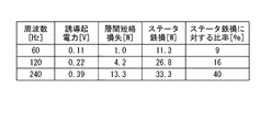
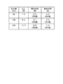
次に、本発明者らは、各励磁周波数で励磁した場合に通常のステータコアの内部に発生する誘導起電力を算出し、算出した誘導起電力と電磁鋼板の電気抵抗率とを用いて、層間短絡損失を算出した。図4に、その結果を表形式で示す。図4において、ステータ鉄損は、各励磁周波数で励磁した場合の通常のステータコアの全鉄損である。また、ステータ鉄損に対する比率は、ステータ鉄損に対する層間短絡損失の割合を百分率で表したものである。図4に示すように、層間短絡損失は、ステータ損失に対して9〜39[%]であり、ステータ損失に影響を与える損失であることが分かる。従って、層間短絡損失は、回転電機の損失を増大させ、回転電機の出力効率を低下させる要因となる。 Next, the present inventors calculate the induced electromotive force generated inside the normal stator core when excited at each excitation frequency, and use the calculated induced electromotive force and the electrical resistivity of the electromagnetic steel plate to make layers between layers. The short circuit loss was calculated. FIG. 4 shows the results in tabular form. In FIG. 4, the stator iron loss is the total iron loss of a normal stator core when excited at each excitation frequency. The ratio to the stator iron loss is the ratio of the interlayer short-circuit loss to the stator iron loss expressed as a percentage. As shown in FIG. 4, the interlayer short-circuit loss is 9 to 39 [%] with respect to the stator loss, and it can be seen that the loss affects the stator loss. Therefore, the interlayer short-circuit loss is a factor that increases the loss of the rotary electric machine and lowers the output efficiency of the rotary electric machine.
以上の知見から本発明者らは、層間短絡損失を抑制するためには、渦電流が流れる経路の一部を電気的に遮断する必要があるという着想を得た。渦電流が流れる経路の一部を電気的に遮断するためには、その部分を電気的に絶縁するのが好ましい。そこで、図1に示すように、例えば、カシメ部115a、115bの間の領域と、カシメ部115a、115cの間の領域とに、それぞれ孔114a、114bを形成する。このようにすれば、孔114a、114b(の内部の空気)により、カシメ部115a、115bの間およびカシメ部115a、115cの間を流れる渦電流をそれぞれ遮断することができる。ここで、孔114a、114bは、ステータコア111を貫通するように形成する。孔114a、114bが、ステータコア111を貫通していないと、孔114a、114bが形成されていない部分が渦電流の経路になり得るからである。
From the above findings, the present inventors have come up with the idea that in order to suppress the interlayer short-circuit loss, it is necessary to electrically cut off a part of the path through which the eddy current flows. In order to electrically block a part of the path through which the eddy current flows, it is preferable to electrically insulate that part. Therefore, as shown in FIG. 1, for example,
また、カシメ部115b、115cの間の領域にも孔114a、114bと同様に孔を形成し、カシメ部115b、115cの間を流れる渦電流を遮断してもよい。ただし、カシメ部115b、115cの径方向の位置は同じである。従って、カシメ部115b、115cの重心の位置を相互に結ぶ仮想線210cを、軸方向に沿って切ることにより得られる断面を鎖交する磁束密度のうち、当該断面に直交する磁束は小さい。よって、カシメ部115b、115cにおいて層間短絡が発生したとしても、この磁束により生じる渦電流は小さい。また、ヨーク部112の周方向における磁束密度は大きい。このため、カシメ部115b、115cの間の領域に孔を形成すると、ヨーク部112の周方向に流れる磁束がこの孔により妨げられる虞がある。以上のことから、カシメ部115b、115cの間の領域には、孔を形成しないのが好ましく、図1(a)に示すように、本実施形態でも、カシメ部115b、115cの間の領域には、孔を形成しない。
Further, holes may be formed in the region between the
一方、径方向における位置が異なる2つのカシメ部の間の領域には、孔を形成するのが好ましい。ただし、径方向における位置が異なる2つのカシメ部の距離が長い場合には、これら2つのカシメ部の間を流れる渦電流の経路も長くなる。従って、径方向における位置が異なる2つのカシメ部の間の領域であっても、これら2つのカシメ部の距離が長い場合には、これら2つのカシメ部の間の領域には、孔を形成しないのが好ましい。例えば、これら2つのカシメ部の周方向の距離が、ヨーク部111の径方向の中心の位置におけるステータコア111の周方向の長さをステータコア111のスロット数で除算した長さを上回る場合、これら2つのカシメ部の間の領域には、孔を形成しないのが好ましい(言い換えると、2つのカシメ部の周方向の距離が、ヨーク部111の径方向の中心の位置におけるステータコア111の周方向の長さをステータコア111のスロット数で除算した長さ以下の場合、これら2つのカシメ部の間の領域には、孔を形成するのが好ましい)。
尚、以上のことは、その他のカシメ部115d〜115rについても同じである。従って、図1に示すように、本実施形態のステータコア111には、孔114c〜114lを形成する。
On the other hand, it is preferable to form a hole in the region between two caulked portions having different positions in the radial direction. However, when the distance between the two caulked portions having different positions in the radial direction is long, the path of the eddy current flowing between the two caulked portions also becomes long. Therefore, even if the region is between two caulked portions having different positions in the radial direction, if the distance between the two caulked portions is long, no hole is formed in the region between the two caulked portions. Is preferable. For example, when the circumferential distance between these two caulked portions exceeds the circumferential length of the
The above is the same for the other caulking portions 115d to 115r. Therefore, as shown in FIG. 1, holes 114c to 114l are formed in the
次に、孔114a〜114lの配置の一例を説明する。図5は、孔114a、114bの配置の一例を示す図である。具体的に図5(a)は、ステータコアの周方向の一部分(約30[°]分)を示す図であり、図1(a)のうち、ティース部113a付近の領域を抜き出して示す図である。図5(b)は、図5(a)のI−I断面図である。
Next, an example of the arrangement of the
前述したように本実施形態では、カシメ部115a、115bの間の領域と、カシメ部115a、115cの間の領域に、それぞれ孔114a、114bを形成する。具体的には、カシメ部115aの重心の位置501と、カシメ部115bの重心の位置502とを相互に結ぶ仮想線511の一部が孔114aの内部に含まれるように孔114aを配置するのが好ましい。同様に、カシメ部115aの重心の位置501と、カシメ部115cの重心の位置503とを相互に結ぶ仮想線512の一部が孔114bの内部に含まれるように孔114bを配置するのが好ましい。即ち、(孔114a、114bが形成されていない場合に)カシメ部115a、115bの間・カシメ部115a、115cの間を流れる渦電流の経路の中心が、孔114a・114bにより遮断されるようにするのが好ましい。以下の説明では、2つのカシメ部の重心の位置を相互に結ぶ仮想線の一部が孔の内部に含まれるように孔を配置することを、必要に応じて、孔の第1の配置条件と称する。
As described above, in the present embodiment, the
そして、(孔114a、114bが形成されていない場合に)カシメ部115a、115bの間およびカシメ部115a、115cの間を流れる渦電流の経路の全体を遮断する観点から、以下のようにするのが好ましい。
即ち、カシメ部115aの第1の端点521と、カシメ部115bの第1の端点522とを相互に結ぶ第1の仮想線531の一部と、カシメ部115aの第2の端点523と、カシメ部115bの第2の端点524とを相互に結ぶ第2の仮想線532の一部とが、孔114aの内部または縁に含まれるように孔114aを配置する。
同様に、カシメ部115aの第1の端点525と、カシメ部115cの第1の端点526とを相互に結ぶ第1の仮想線533の一部と、カシメ部115aの第2の端点527と、カシメ部115cの第2の端点527とを相互に結ぶ第2の仮想線534の一部とが、孔114bの内部または縁に含まれるように孔114bを配置する。
以下の説明では、或るカシメ部の第1の端点と、他のカシメ部の第1の端点とを相互に結ぶ第1の仮想線の一部と、当該或るカシメ部の第2の端点と、当該他のカシメ部の第2の端点とを相互に結ぶ第2の仮想線の一部とが、孔の内部または縁に含まれるように孔を配置することを、必要に応じて、孔の第2の配置条件と称する。
Then, from the viewpoint of blocking the entire path of the eddy current flowing between the
That is, a part of the first virtual line 531 connecting the
Similarly, a part of the first
In the following description, a part of a first virtual line connecting a first end point of a certain caulking part and a first end point of another caulking part to each other, and a second end point of the certain caulking part. And, if necessary, arrange the hole so that a part of the second virtual line connecting the other crimped portion with the second end point is included in the inside or the edge of the hole. This is referred to as the second arrangement condition of the holes.
ここで、カシメ部の端点は、電磁鋼板の板面に対して垂直な方向に沿ってカシメ部を見たとき(即ち、カシメ部を平面視したとき)のカシメ部の領域の輪郭上の点を指す(このことは、他の説明においても同じである)。また、第1の仮想線531(533)および第2の仮想線532(534)は、カシメ部115aの何れかの端点と、カシメ部115b(115c)の何れかの端点とを相互に結ぶ仮想線と、カシメ部115aのその他の端点と、カシメ部115b(115c)のその他の端点とを相互に結ぶ仮想線と、カシメ部115a、115b(115a、115c)とで囲まれる領域の面積が最大になるときの当該仮想線である。ここで、第1の仮想線531(533)が、ティース部113aの周方向における端面551、552とヨーク部112の内周面571、572との連結部分にできる2つの曲部561、562よりもステータコア111の外側を通り、第1の仮想線531(533)にステータコア111の領域を通らない部分がある場合には、第1の仮想線531(533)に代えて、第3の仮想線を採用する。
Here, the end points of the crimped portion are points on the contour of the region of the crimped portion when the crimped portion is viewed along the direction perpendicular to the plate surface of the electromagnetic steel plate (that is, when the crimped portion is viewed in a plan view). (This is the same in other explanations). Further, the first virtual line 531 (533) and the second virtual line 532 (534) are virtual lines connecting any end point of the
第3の仮想線は、カシメ部115a、115bの領域を通らないように、カシメ部115aの第1の端点521およびカシメ部115bの第1の端点522と、曲部561の点とをそれぞれ相互に結ぶ仮想線と、カシメ部115aの第1の端点525およびカシメ部115cの第1の端点526と、曲部562の点とをそれぞれ相互に結ぶ仮想線になる。このように第3の仮想線は、直線ではなく、屈曲線になる(後述する図6Aおよび図6Bの第3の仮想線611〜622を参照)。ここで、第3の仮想線の屈曲点に位置する曲部の候補として、2つの曲部561、562があるが、第3の仮想線の屈曲点に位置する曲部は、これら2つの曲部561、562のうち、当該第3の仮想線で代替する第1の仮想線531、532との距離が近い方の曲部になる。例えば、後述する図6Aにおいて、第3の仮想線611で代替する第1の仮想線は、カシメ部115aの左下の頂点とカシメ部115bの左下の頂点とを相互に結ぶ第1の仮想線である。従って、曲部561、562のうち、この第1の仮想線との距離が近い曲部561が、第3の仮想線611の屈曲点に位置する曲部となる。同様に、第3の仮想線612で代替する第1の仮想線は、カシメ部115aの右下の頂点とカシメ部115cの右下の頂点とを相互に結ぶ第1の仮想線である。従って、曲部561、562のうち、この第1の仮想線との距離が近い曲部562が、第3の仮想線612の屈曲点に位置する曲部となる。また、曲部561、562の点は、電磁鋼板の板面に対して垂直な方向に沿って曲部561、562を見たときの曲部561、562の領域の所定の位置の点である。所定の位置は、例えば、曲部561、562が曲率を有している場合には、曲率半径が最大になる曲部561、562上の位置であり、曲部561、562が屈曲している場合には、当該屈曲している位置である。
The third virtual line crosses the
尚、図5(b)において、孔114a、114bは、ステータコア111の、軸方向における一方の端面541から他方の端面542まで貫通する貫通孔である。具体的に図5(b)に示す例では、孔114a、114bは、軸方向においてステータコア111を貫通する貫通孔である。尚、孔114a、114bは、空隙であり、何も配置されていない。
In FIG. 5B, the
また、以上のような配置でステータコア111を貫通していれば、孔の形状、位置、および大きさは、図5に示したものに限定されない。図6Aおよび図6Bに、孔の変形例を示す。図6Aの(a)〜(c)、図6Bの(a)〜(b)は、孔の第1〜第5の変形例であり、図5(a)に対応する図である。
図5に示した例では、孔114a、114bを、ヨーク部112とティース部113aとの境界部分に形成した。しかしながら、図6Aの(a)に示すように、孔601、602をティース部113aに形成してもよい。また、図6Aの(b)に示すように、孔603、604を、ヨーク部112に形成してもよい。
Further, as long as the
In the example shown in FIG. 5,
また、図5に示した例では、カシメ部115a、115bの間と、カシメ部115a、115cの間に対し、それぞれ個別に孔114a、114bを形成した。しかしながら、図6Aの(c)に示すように、カシメ部115a、115bの間と、カシメ部115a、115cの間とに対し、1つの孔605を形成してもよい。
Further, in the example shown in FIG. 5,
また、図5に示した例では、矩形状の孔114a、114bの長辺の方向が径方向に沿うようにした。しかしながら、図6Bの(a)に示すように、矩形状の孔606、607の長辺の方向を周方向にし、且つ、孔606、607をヨーク部112に形成してもよい。また、図6(B)の(b)に示すように、矩形状の孔608、609の長辺の方向を周方向にし、且つ、孔608、609をティース部113aに形成してもよい。また、図示は省略するが、矩形状の孔の長辺の方向を周方向にし、且つ、孔をヨーク部112とティース部113aとの境界部分に形成してもよい。
Further, in the example shown in FIG. 5, the directions of the long sides of the
この他、孔の形状は、図5(a)や図6Aおよび図6Bに示すように矩形である必要はない。例えば、孔の形状は、第1の仮想線531(533)および第2の仮想線532(534)に平行な辺を有する平行四辺形でもよい。その他、孔の形状は、円であっても、楕円であってもよい。また、曲部561、562の位置に孔を配置してもよい。曲部561、562の近くに孔を配置すると、曲部561、562と孔と間の隙間が小さくなり、磁束密度の分布に大きな偏りが生じる虞がある。従って、曲部561、562の近くに孔を配置するのであれば、曲部561、562に孔を配置する方が好ましい。尚、このようにする場合、曲部は、孔の縁になるため、第3の仮想線の一部は、当該孔の縁を通ることになる。
In addition, the shape of the hole does not have to be rectangular as shown in FIG. 5A, FIG. 6A and FIG. 6B. For example, the shape of the hole may be a parallelogram having sides parallel to the first virtual line 531 (533) and the second virtual line 532 (534). In addition, the shape of the hole may be a circle or an ellipse. Further, holes may be arranged at the positions of the
尚、その他の孔114c〜114lの配置も、以上の孔114a、114bの配置と同様にして定めることができる。従って、ここでは、その他の孔114c〜114lの配置の詳細な説明を省略する。
The arrangement of the other holes 114c to 114l can be determined in the same manner as the arrangement of the
また、本発明者らは、孔の有無により層間短絡損失がどのように変わるのかを検証した。その結果を図7に示す。図4に示した結果と同様に、各励磁周波数で励磁した場合にステータコアの内部に発生する誘導起電力を算出し、算出した誘導起電力と電磁鋼板の電気抵抗率を用いて、層間短絡損失を算出した。図7において、「なし」は、孔を形成していない通常のステータコアに対する結果(即ち、図4に示した結果)を示す。「縦長形状」は、図5、図6Aに示したように、孔の形状を、長辺の方向が周方向に沿う方向である矩形にしたステータコアに対する結果であることを示す。また、「横長形状」は、図6Bに示したように、孔の形状を、長辺の方向が径方向に沿う方向である矩形にしたステータコアに対する結果であることを示す。これ以外については、「横長形状」の孔と「縦長形状」の孔は同じ条件であるものとする。また、孔の以外の条件は、「なし」、「横長形状」、および「縦長形状」で同じであるものとする。また、ここでは、孔の電気抵抗率が106[Ω・m]であるとして計算を行った。 In addition, the present inventors have verified how the interlayer short-circuit loss changes depending on the presence or absence of holes. The result is shown in FIG. Similar to the result shown in FIG. 4, the induced electromotive force generated inside the stator core when excited at each excitation frequency is calculated, and the calculated induced electromotive force and the electrical resistivity of the electromagnetic steel plate are used to generate an interlayer short-circuit loss. Was calculated. In FIG. 7, “none” indicates the result for a normal stator core without holes (ie, the result shown in FIG. 4). The "vertical shape" indicates that, as shown in FIGS. 5 and 6A, the shape of the hole is the result of a rectangular stator core in which the direction of the long side is along the circumferential direction. Further, the "horizontally elongated shape" indicates that, as shown in FIG. 6B, the shape of the hole is a result for a stator core having a rectangular shape in which the direction of the long side is along the radial direction. Other than this, it is assumed that the "horizontally elongated" hole and the "vertically elongated" hole have the same conditions. In addition, the conditions other than the holes are the same for "none", "horizontally elongated shape", and "vertically elongated shape". Further, here, the electric resistivity of the hole was calculated as a 10 6 [Ω · m].
図7に示すように、ステータコアに孔を形成することにより、層間短絡損失を低減することができることが分かる。また、図7に示す結果では、「縦長形状」にする方が「横長形状」にするよりも、渦電流の経路を横切る孔の長さが長くなる。このため、「縦長形状」にする方が「横長形状」にするよりも、層間短絡損失を低減することができる。このように、孔の内部において、渦電流の経路の長さが長くなるように、孔の形状を定めるのが好ましい。また、孔の大きさを大きくした方が、層間短絡損失を大きくすることができるが、孔の大きさを大きくし過ぎると、ステータコアの内部の磁束の流れを孔が妨げる。孔の大きさは、このような観点から、ステータコアのトータルの鉄損が低減するように定めるのが好ましい。 As shown in FIG. 7, it can be seen that the interlayer short circuit loss can be reduced by forming holes in the stator core. Further, in the result shown in FIG. 7, the length of the hole crossing the path of the eddy current is longer in the "vertical shape" than in the "horizontal shape". Therefore, the interlayer short-circuit loss can be reduced in the "vertical shape" as compared with the "horizontal shape". In this way, it is preferable to determine the shape of the hole so that the length of the eddy current path becomes long inside the hole. Further, the interlayer short-circuit loss can be increased by increasing the size of the hole, but if the size of the hole is increased too much, the hole hinders the flow of the magnetic flux inside the stator core. From this point of view, the hole size is preferably determined so that the total iron loss of the stator core is reduced.
以上のように本実施形態では、カシメ部115a、115bの間の領域と、カシメ部115a、115cの間の領域に、ステータコア111の、軸方向における一方の端面541から他方の端面542まで貫通する孔114a、114bを形成する。従って、孔114a、114bが形成されていない場合にカシメ部115a、115bの間とカシメ部115a、115cの間とを流れる渦電流の経路の少なくとも一部を遮断することができる。これにより、層間短絡損失を低減することができる。また、カシメ部115a、115bの間の領域と、カシメ部115a、115cの間の領域に、孔114a、114bを作製すればよいので、ステータコア111の形状に合わせて、ステータコア111の内部の磁束密度に大きな偏りが生じないように孔114a、114bの位置および大きさを決めることができる。よって、孔114a、114bを形成することによる損失が大きくならないようにすることができる。さらに、製作する電磁鋼板を一種類にすることができ、複数種類の鋼板を組み合わせたり、複数種類の金型を用いたりする必要がなくなる。これにより、ステータコア111の製造工程を簡略することができる。また、ステータコア111を構成する複数の電磁鋼板を一括してかしめるので、かしめによるステータコア111の連結を確実に行うことができる。
As described above, in the present embodiment, the region between the
ここで、本実施形態では、2つのカシメ部115a、115b(115a、115c)の間の領域に、ステータコア111の、軸方向における一方の端面541から他方の端面542まで貫通する孔114a(114b)、即ち空隙を形成する場合を例に挙げて説明した。しかしながら、このような孔114a、114bは、2つのカシメ部の間の領域において、ステータコアの、軸方向における一方の端面から他方の端面まで繋がるように形成される高抵抗領域の一例に過ぎず、このような高抵抗領域を形成するようにしていれば、必ずしもこのようにする必要はない。ここで、高抵抗領域とは、ステータコア111を構成する電磁鋼板の電気抵抗率よりも電気抵抗率が高い領域をいい、好ましくは、ステータコア111を構成する電磁鋼板の電気抵抗率の10倍以上、より好ましくは、ステータコア111を構成する電磁鋼板の電気抵抗率の100倍以上の電気抵抗率を有する領域である。ステータコア111を構成する電磁鋼板の電気抵抗率の10倍以上、好ましくは100倍以上の電気抵抗率を有する材料を、孔に配置してもよい。このような材料としては、例えば、ベークライト(フェノール樹脂)等のプラスチックや、高分子加工物や、耐熱ゴムがある。このようにすれば、空隙にする場合に比べ、電気抵抗率が低くなることがあるが、ステータコアの剛性を高めることができる。
Here, in the present embodiment, the
また、かしめの方法は、公知の方法で実現でき、カシメ部115a〜115rの形状は、かしめの方法に応じて定まる。本実施形態では、かしめが角かしめである場合を例に挙げて示した。しかしながら、丸平かしめ、丸Vかしめ、角平かしめ、角Vかしめ等公知のかしめを採用することができる。また、1つのステータコアにおいて使用するかしめは一種類に限定されず、複数種類のかしめを混在させてもよい。
Further, the caulking method can be realized by a known method, and the shapes of the caulked
(第2の実施形態)
次に、第2の実施形態を説明する。第1の実施形態では、複数の電磁鋼板の全てを周方向においてずらさずに積層し、ティース部113aの周方向における一方および他方の端面551、552が、軸方向に沿うようにする場合を例に挙げて説明した。これに対し、本実施形態では、複数の電磁鋼板の少なくとも一部を周方向においてずらして積層し、ティース部の周方向における一方および他方の端面が、軸方向に対し傾斜する領域を有する場合(即ち、ステータコアがスキューを有する場合)を例に挙げて説明する。このように本実施形態と第1の実施形態とは、複数の電磁鋼板の積層の仕方が異なることによる構成が主として異なる。従って、本実施形態の説明において、第1の実施形態と同一の部分については、図1〜図7に付した符号と同一の符号を付す等して詳細な説明を省略する。スキューを設ける方法としては種々の方法があるが、本実施形態では、スキューを有するステータコアの例として以下の第1および第2の例について説明する。
(Second embodiment)
Next, the second embodiment will be described. In the first embodiment, there is an example in which all of the plurality of electrical steel sheets are laminated without shifting in the circumferential direction so that one and the other end faces 551 and 552 of the
<第1の例>
図8は、本実施形態の回転電機の構成の第1の例を示す図である。図8は、回転電機800を軸方向に沿って見た図である。図8は、図1(a)に対応する図である。
回転電機800は、ステータ810と、ロータ120とを有する。ステータ810は、ステータコア811を有する。ステータコア811は、ヨーク部(コアバック部)812と、複数のティース部813a〜813lとを有する。図8に示すように、ステータコア811には、孔814a〜814lが形成されている。ヨーク部812、複数のティース部813a〜813l、および孔814a〜814lの形状に合うように、母材(磁性体板)に対して打ち抜き加工を施すことにより、ステータコア811を構成する磁性体板が形成される。ステータコア811を構成する磁性体板は、いずれも同じ形状および大きさを有する。本実施形態でも第1の実施形態と同様に磁性体板として電磁鋼板を用いる場合を例に挙げて説明する。
<First example>
FIG. 8 is a diagram showing a first example of the configuration of the rotary electric machine of the present embodiment. FIG. 8 is a view of the rotary
The rotary
図9は、孔814a、814bの配置の一例を示す図である。具体的に図9(a)は、ステータコアの周方向の一部分(約30[°]分)を示す図であり、図8のうち、ティース部813a付近の領域を抜き出して示す図である。図9(b)は、図9(a)のI−I断面図である。
FIG. 9 is a diagram showing an example of arrangement of
本実施形態では、図9(a)および図9(b)に示すように、以上のような複数の電磁鋼板を、ヨーク部812に対応する位置が合うようにすると共に、ティース部813a〜813lおよび孔814a〜814lに対応する位置がそれぞれ周方向において一方向(図9に示す例では、紙面の手前から奥に向かって左側の方向)にずれるように積層した状態で、かしめる。このようにして複数の電磁鋼板をかしめることにより、ティース部813aの周方向における一方および他方の端面951、952が、軸方向に対し傾斜する領域を有する。また、孔814a、814bは、ステータコア811の、軸方向における一方の端面941から他方の端面942まで貫通する貫通孔である。第1の実施形態では、孔114a、114bは、軸設方向においてステータコア111を貫通する貫通孔である(図5(b)を参照)。これに対し、本例では、図9(b)に示すように、孔814a、814bは、軸方向に対し一方向に傾斜した状態でステータコア811を貫通する貫通孔である。一方、図9(b)にカシメ部815aを例に挙げて示すように、カシメ部815a〜815cの周方向の位置は、軸方向の位置に関わらず同じである。
In the present embodiment, as shown in FIGS. 9A and 9B, the plurality of electromagnetic steel sheets as described above are aligned with the
本例でも、第1の実施形態と同様に、前述した孔の第1の配置条件を満たすようにするのが好ましい。
即ち、カシメ部815aの重心の位置901と、カシメ部815bの重心の位置902とを相互に結ぶ仮想線911の一部が孔814aの内部に含まれるように孔814aを配置する。同様に、カシメ部815aの重心の位置901と、カシメ部815cの重心の位置903とを相互に結ぶ仮想線912の一部が孔814bの内部に含まれるように孔814bを配置する。
Also in this example, as in the first embodiment, it is preferable to satisfy the first arrangement condition of the holes described above.
That is, the
また、前述した第2の配置条件を満たすようにするのが好ましい。
即ち、カシメ部815aの第1の端点921と、カシメ部815bの第1の端点922とを相互に結ぶ第1の仮想線931の一部と、カシメ部815aの第2の端点923と、カシメ部815bの第2の端点924とを相互に結ぶ第2の仮想線932の一部とが、孔814aの内部または縁に含まれるように孔814aを配置する。
同様に、カシメ部815aの第1の端点925と、カシメ部815cの第1の端点926とを相互に結ぶ第1の仮想線933の一部と、カシメ部815aの第2の端点927と、カシメ部815cの第2の端点927とを相互に結ぶ第2の仮想線934の一部とが、孔814bの内部または縁に含まれるように孔814bを配置する。
Further, it is preferable to satisfy the above-mentioned second arrangement condition.
That is, a part of the first
Similarly, a part of the first
尚、第1の仮想線931、933にステータコア811の領域を通らない部分がある場合には、第1の仮想線931、933に代えて、第3の仮想線を採用することは第1の実施形態で説明した通りである。
また、図9(b)に示すように、軸方向の位置により、孔814a〜814lとカシメ部815a〜815rとの距離が変わる。従って、このことを考慮して、軸方向の位置に関わらず、前述した第1の配置条件または第2の配置条件ように孔814a〜814lの位置、大きさ、および形状を定めるのが好ましい。
If the first
Further, as shown in FIG. 9B, the distance between the
<第2の例>
第1の例では、ティース部813aの周方向における一方および他方の端面951、952が、軸方向に対し、一方向(図9の紙面の手前から奥に向かって左方向)に傾斜する場合を示した。前述したように、ティース部の周方向における一方および他方の端面が、軸方向に対し傾斜する領域を有していれば、このようにする必要はない。本例では、ティース部の周方向における一方および他方の端面が、軸方向に対し、一方向に傾斜する領域と他方向に傾斜する領域とを有する場合について説明する。
<Second example>
In the first example, one and the other end faces 951 and 952 in the circumferential direction of the
図10は、本実施形態の回転電機の構成の第2の例を示す図である。図10は、回転電機1000を軸方向に沿って見た図である。図10は、図1(a)に対応する図である。
回転電機1000は、ステータ1010と、ロータ120とを有する。ステータ1010は、ステータコア1011を有する。ステータコア1011は、ヨーク部(コアバック部)1012と、複数のティース部1013a〜1013lとを有する。図10に示すように、ステータコア1011には、孔1014a〜1014lが形成されている。ヨーク部1012、複数のティース部1013a〜1013l、および孔1014a〜1014lの形状に合うように、母材(電磁鋼板)に対して打ち抜き加工を施すことにより、ステータコア1011を構成する電磁鋼板が形成される。ステータコア1011を構成する電磁鋼板は、いずれも同じ形状および大きさを有する。
FIG. 10 is a diagram showing a second example of the configuration of the rotary electric machine of the present embodiment. FIG. 10 is a view of the rotary
The rotary
図11は、孔1014a、1014bの配置の一例を示す図である。具体的に図11(a)は、ステータコアの周方向の一部分(約30[°]分)を示す図であり、図10のうち、ティース部1013a付近の領域を抜き出して示す図である。図11(b)は、図11(a)のI−I断面図である。
FIG. 11 is a diagram showing an example of arrangement of
本実施形態では、図11(a)および図11(b)に示すように、以上のような複数の電磁鋼板を、ヨーク部812に対応する位置が合うようにすると共に、ティース部813a〜813lおよび孔814a〜814lに対応する位置が、それぞれ、軸方向の一方の端面1141から軸方向の中央までは、周方向において一方向(図9に示す例では、紙面の手前から奥に向かって左側の方向)にずれ、軸方向の中央から軸方向の他方の端面1142までは、周方向において他方向(図9に示す例では、紙面の手前から奥に向かって右側の方向)にずれるように積層した状態で、かしめる。このようにして複数の電磁鋼板をかしめることにより、ティース部1013aの周方向における一方および他方の端面1151、1152が、軸方向に対し傾斜する領域を有する。また、孔1014a、1014bは、ステータコア1011の、軸方向における一方の端面1141から他方の端面1142まで貫通する貫通孔である。第1の例では、孔814a、814bは、軸方向に対し一方向に傾斜した状態でステータコア111を貫通する貫通孔である(図9(b)を参照)。これに対し、本例では、図11(b)に示すように、孔1014a、1014bは、軸方向に対し、軸方向の一方の端面1141から軸方向の中央までは一方向に傾斜し、軸方向の中央から軸方向の他方の端面1142までは他方向に傾斜した状態でステータコア1011を貫通する貫通孔である。第1の例と同様に、カシメ部1015a〜1015cの周方向の位置は、軸方向の位置に関わらず同じである(図11(b)のカシメ部1015aの位置を参照)。
In the present embodiment, as shown in FIGS. 11A and 11B, the plurality of electromagnetic steel sheets as described above are aligned with the
本例でも、第1の実施形態および本実施形態の第1の例と同様に、前述した孔の第1の配置条件を満たすようにするのが好ましい。
即ち、カシメ部1015aの重心の位置1101と、カシメ部1015bの重心の位置1102とを相互に結ぶ仮想線1111の一部が孔1014aの内部に含まれるように孔1014aを配置する。同様に、カシメ部1015aの重心の位置1101と、カシメ部1015cの重心の位置1103とを相互に結ぶ仮想線1112の一部が孔1014bの内部に含まれるように孔1014bを配置する。
In this example as well, as in the first embodiment and the first example of the present embodiment, it is preferable to satisfy the condition of the first arrangement of the holes described above.
That is, the
また、前述した第2の配置条件を満たすようにするのが好ましい。
即ち、カシメ部1015aの第1の端点1121と、カシメ部1015bの第1の端点1122とを相互に結ぶ第1の仮想線1131の一部と、カシメ部1015aの第2の端点1123と、カシメ部1015bの第2の端点1024とを相互に結ぶ第2の仮想線1132の一部とが、孔1014aの内部または縁に含まれるように孔1014aを配置する。
同様に、カシメ部1015aの第1の端点1125と、カシメ部1015cの第1の端点1126とを相互に結ぶ第1の仮想線1133の一部と、カシメ部1015aの第2の端点1127と、カシメ部1015cの第2の端点1128とを相互に結ぶ第2の仮想線1134の一部とが、孔1014bの内部または縁に含まれるように孔1014bを配置する。
Further, it is preferable to satisfy the above-mentioned second arrangement condition.
That is, a part of the first
Similarly, a portion of the first
尚、第1の仮想線1131、1133にステータコア1011の領域を通らない部分がある場合には、第1の仮想線1131、1133に代えて、第3の仮想線を採用することは第1の実施形態で説明した通りである。
また、第1の例と同様に、本例でも、図11(b)に示すように、軸方向の位置により、孔1014a〜1014lとカシメ部1015a〜1015rとの距離が変わる。従って、このことを考慮して、軸方向の位置に関わらず、前述した第1の配置条件または第2の配置条件ように孔1014a〜1014lの位置、大きさ、および形状を定めるのが好ましい。
If the first
Further, as in the first example, in this example as shown in FIG. 11B, the distance between the
以上のように本実施形態では、ステータコアにスキューを設けるので、第1の実施形態で説明した効果に加え、回転電機800、1000のトルクの時間変動を抑制することができるという効果が得られる。
尚、前述した第1の例および第2の例では、ティース部の周方向における一方および他方の端面の全ての領域が、軸方向に対し傾斜する場合を示した。しかしながら、ティース部の周方向における一方および他方の端面の一部の領域が、軸方向に対し傾斜し、残りの一部の領域が、軸方向に沿うようにしてもよい(即ち、ティース部の周方向における一方および他方の端面の一部の領域が、傾斜していなくてもよい)。また、本実施形態においても、第1の実施形態で説明した種々の変形例を採用することができる。
As described above, in the present embodiment, since the stator core is provided with the skew, in addition to the effect described in the first embodiment, the effect of suppressing the time fluctuation of the torque of the rotary
In the first example and the second example described above, the case where all the regions of one and the other end faces in the circumferential direction of the teeth portion are inclined with respect to the axial direction is shown. However, some regions of one and the other end faces in the circumferential direction of the teeth portion may be inclined with respect to the axial direction, and the remaining part region may be along the axial direction (that is, the teeth portion may be aligned. Some areas of one and the other end faces in the circumferential direction do not have to be tilted). Further, also in this embodiment, various modifications described in the first embodiment can be adopted.
(第3の実施形態)
次に、第3の実施形態について説明する。前述した第1、第2の実施形態では、ステータコア111、811、1011が周方向において一体である一体型ステータコアである場合を例に挙げて説明した。これに対し、本実施形態では、ステータコアが、周方向において分割された分割型ステータコアである場合を例に挙げて説明する。このように本実施形態は、第1、第2の実施形態に対し、ステータコアを分割型ステータコアとしたことによる構成が主として異なる。従って、従って、本実施形態の説明において、第1、第2の実施形態と同一の部分については、図1〜図11に付した符号と同一の符号を付す等して詳細な説明を省略する。
(Third Embodiment)
Next, a third embodiment will be described. In the first and second embodiments described above, the case where the
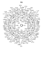
図12は、本実施形態の回転電機の構成の一例を示す図である。図12は、回転電機1200を軸方向に沿って見た図である。図12は、図1(a)に対応する図である。
回転電機1200は、ステータ1210と、ロータ120とを有する。ステータ1210は、ステータコア1211を有し、ステータコア1211は、複数のステータコア片1211a〜1211lを有する。
複数のステータコア片1211a〜1211lは、それぞれ、周方向に延在するヨーク片1212a〜1212lと、当該ヨーク片1212a〜1212lの内周面から軸芯に向かう方向に延在するティース片1213a〜1213lとを有する。複数のステータコア片1211a〜1211lは、軸方向に沿って積層された複数の磁性体板を用いて構成される。本実施形態でも、第1の実施形態と同様に磁性体板が、電磁鋼板である場合を例に挙げて説明する。
FIG. 12 is a diagram showing an example of the configuration of the rotary electric machine of the present embodiment. FIG. 12 is a view of the rotary
The rotary
The plurality of
図12に示すように、複数のステータコア片1211a〜1211lには、それぞれ、孔1214a〜1214xが形成されている。ヨーク片1212a〜1212l、ティース片1213a〜1213l、および孔1214a〜1214xの形状に合うように、母材(電磁鋼板)に対して打ち抜き加工を施すことにより、ステータコア片1211a〜1211lを構成する電磁鋼板が形成される。ステータコア片1211a〜1211lを構成する電磁鋼板は、いずれも同じ形状および大きさを有する。
As shown in FIG. 12,
このようにして得られた複数の電磁鋼板を、ヨーク片1212a〜1212l、ティース片1213a〜1213l、および孔1214a〜1214xに対応する位置がそれぞれ合うように積層した状態で、かしめる。このようにして複数の電磁鋼板をかしめることにより、カシメ部1215a1〜1215l3が形成される。また、孔1214a〜1214lは、複数の電磁鋼板の積層方向(軸方向)においてステータコア片1211a〜1211lを貫通する。このように、複数のステータコア片1211a〜1211lは、同じ形状および大きさを有し、同じもので実現できる。
The plurality of electrical steel sheets thus obtained are crimped in a state of being laminated so that the positions corresponding to the
以上のようにして得られた複数のステータコア片1211a〜1211lを、周方向において組み合わせることにより、ステータコア1211が構成される。即ち、複数のステータコア片1211a〜1211lのヨーク片1212a〜1212lが組み合わさることにより、ステータコア1211のヨーク部が構成される。また、ティース片1213a〜1213lのそれぞれが、ステータコア1211のティース部となる。
The
尚、複数のステータコア片1211a〜1211lを、周方向において組み合わせる際には、相互に隣接する位置のステータコア片(例えば、ステータコア片1211aに隣接するのはステータコア片1211b、1211l)の周方向の端面同士が対向するようにする。
When a plurality of
本実施形態でも、第1、第2の実施形態と同様に、前述した孔の第1の配置条件または第2の配置条件を満たすようにするのが好ましい。第1の実施形態で説明したように、ヨーク部の径方向の中心の位置におけるステータコア1211の周方向の長さをステータコア1211のスロット数で除算した長さ以下の場合、これら2つのカシメ部の間の領域には、孔を形成するのが好ましい。このような観点から、カシメ部1215a1と、カシメ部1215a2、1215a3、1215b2、1215l3との間の領域に、孔1214a、1214bを形成する。ここで、本実施形態では、孔1214aは、カシメ部1215a1と、カシメ部1215a2、1215l3の双方とについて、前述した孔の第1の配置条件および第2の配置条件を満たすように形成している。同様に、孔1214bは、カシメ部1215a1と、カシメ部1215a3、1215b2の双方とについて、前述した孔の第1の配置条件および第2の配置条件を満たすように形成している。以上のことはその他の孔についても同様である。
Also in this embodiment, as in the first and second embodiments, it is preferable to satisfy the first arrangement condition or the second arrangement condition of the holes described above. As described in the first embodiment, when the length in the circumferential direction of the
ただし、異なるステータコア片に存在する2つのかしめ部の間の領域には、孔を形成しなくてもよい。また、図12では、複数のステータコア片1211a〜1211lを、同じもので実現する場合を例に挙げて示した。しかしながら、カシメ部の位置などに応じて、前述した孔の第1の配置条件または第2の配置条件を満たすために、少なくとも2つのステータコア片の孔の数、位置、大きさ、および形状の少なくとも1つを異ならせてもよい。その他、本実施形態においても、第1の実施形態で説明した種々の変形例を採用することができる。また、第2の実施形態で説明したようなスキューを分割型ステータコアに設けてもよい。
However, it is not necessary to form a hole in the region between the two caulked portions existing in different stator core pieces. Further, in FIG. 12, a case where a plurality of
(第4の実施形態)
次に、第4の実施形態について説明する。第1〜第3の実施形態では、複数の磁性体板をかしめにより機械的に連結する場合を例に挙げて説明した。これに対し、本実施形態では、複数の磁性体板をかしめに加えて溶接を用いて連結する。このように本実施形態と第1〜第3の実施形態とは、複数の磁性体板を連結する方法が異なることによる構成が主として異なる。従って、本実施形態の説明において、第1〜第3の実施形態と同一の部分については、図1〜図12に付した符号と同一の符号を付す等して詳細な説明を省略する。
(Fourth Embodiment)
Next, a fourth embodiment will be described. In the first to third embodiments, a case where a plurality of magnetic plates are mechanically connected by caulking has been described as an example. On the other hand, in the present embodiment, a plurality of magnetic plates are added to the caulking and connected by welding. As described above, the present embodiment and the first to third embodiments are mainly different in configuration due to the difference in the method of connecting the plurality of magnetic plate. Therefore, in the description of the present embodiment, detailed description will be omitted by assigning the same reference numerals as those given in FIGS. 1 to 12 to the same parts as those in the first to third embodiments.
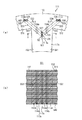
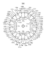
図13は、本実施形態の回転電機の構成の一例を示す図である。図13は、回転電機1300を軸方向に沿って見た図である。図13は、図1(a)に対応する図である。
回転電機1300は、ステータ1310と、ロータ120とを有する。ステータ1310は、ステータコア1311を有する。ステータコア1311は、ヨーク部(コアバック部)1312と、複数のティース部1313a〜1313lとを有する。図13に示すように、ステータコア1311には、孔1314a〜1314xが形成されている。ヨーク部1312、複数のティース部1313a〜1313l、および孔1314a〜1314xの形状に合うように、母材(磁性体板)に対して打ち抜き加工を施すことにより、ステータコア1311を構成する磁性体板が形成される。ステータコア1311を構成する磁性体板は、いずれも同じ形状および大きさを有する。本実施形態でも第1の実施形態と同様に磁性体板として電磁鋼板を用いる場合を例に挙げて説明する。
FIG. 13 is a diagram showing an example of the configuration of the rotary electric machine of the present embodiment. FIG. 13 is a view of the rotary
The rotary
このようにして得られた複数の電磁鋼板を、ヨーク部1312、ティース部1313a〜1313l、および孔1314a〜1314xに対応する位置がそれぞれ合うように積層した状態で、かしめる。このようにして複数の電磁鋼板をかしめることにより、カシメ部1315a〜1315xが形成される。その後、周方向の複数の位置において、ヨーク部1312の外周面に対し、軸方向の全体に亘って、溶接を行う。このようにして溶接を行うことにより、溶接部1316a〜1316lが形成される。溶接部1316a〜1316lは、もとの電磁鋼板が溶融した後に凝固した部分である。溶接部1316a〜1316lは、複数の電磁鋼板を熱的に連結する連結部の一例である。尚、溶接部の数、位置、および範囲は、複数の電磁鋼板を連結することができれば、特に限定されない。以上のようにして複数の電磁鋼板を連結することにより、孔1314a〜1314xは、複数の電磁鋼板の積層方向(軸方向)においてステータコア1311を貫通する。
The plurality of electrical steel sheets thus obtained are crimped in a state of being laminated so that the positions corresponding to the
本実施形態でも、第1、第2の実施形態と同様に、前述した孔の第1の配置条件または第2の配置条件を満たすようにするのが好ましい。ただし、第1の実施形態で説明した孔の第1の配置条件および第2の配置条件において、カシメ部115a、115d、115g、115j、115m、115pが、溶接部1316a〜1316lに置き換わる。ここで、溶接部の重心の位置は、電磁鋼板の板面に対して垂直な方向に沿って溶接部を見たとき(即ち、溶接部を平面視したとき)の溶接部の領域の輪郭を縁とする平面の重心の位置を指す。また、溶接部の端点は、電磁鋼板の板面に対して垂直な方向に沿って溶接部を見たとき(即ち、溶接部を平面視したとき)の溶接部の領域の端点を指す。
Also in this embodiment, as in the first and second embodiments, it is preferable to satisfy the first arrangement condition or the second arrangement condition of the holes described above. However, in the first arrangement condition and the second arrangement condition of the holes described in the first embodiment, the caulked
第1の実施形態で説明したように、ヨーク部1312の径方向の中心の位置におけるステータコア1311の周方向の長さをステータコア1311のスロット数で除算した長さ以下の場合、これら2つのカシメ部の間の領域には、孔を形成するのが好ましい。このことは、カシメ部が溶接部に置き換わっても同じである。このような観点から、溶接部1316aと、カシメ部1315a、1315x、1315b、1315cとの間の領域に、孔1314a、1314bを形成する。ここで、本実施形態では、孔1314aは、溶接部1316aと、カシメ部1315a、1315xの双方とについて、前述した孔の第1の配置条件および第2の配置条件を満たすように形成している。同様に、孔1314bは、溶接部1316aと、カシメ部1315b、1315cの双方とについて、前述した孔の第1の配置条件および第2の配置条件を満たすように形成している。以上のことはその他の孔についても同様である。
As described in the first embodiment, when the length in the circumferential direction of the
図13は、孔1314a、1314bの配置の一例を示す図である。具体的に図13は、ステータコアの周方向の一部分(約60[°]分)を示す図であり、図13のうち、ティース部1313a付近の領域を抜き出して示す図である。
FIG. 13 is a diagram showing an example of arrangement of
本例でも、第1の実施形態と同様に、前述した孔の第1の配置条件を満たすようにするのが好ましい。
即ち、溶接部1316aの重心の位置1401と、カシメ部1315aの重心の位置1402aとを相互に結ぶ仮想線1411aの一部が孔1314aの内部に含まれるように孔1314aを配置する。更に、溶接部1316aの重心の位置1401と、カシメ部1315xの重心の位置1403aとを相互に結ぶ仮想線1412aの一部が孔1314aの内部に含まれるように孔1314aを配置する。
Also in this example, as in the first embodiment, it is preferable to satisfy the first arrangement condition of the holes described above.
That is, the
同様に、溶接部1316aの重心の位置1401と、カシメ部1315bの重心の位置1402bとを相互に結ぶ仮想線1411bの一部が孔1314bの内部に含まれるように孔1314bを配置する。更に、溶接部1316aの重心の位置1401と、カシメ部1315cの重心の位置1403bとを相互に結ぶ仮想線1412bの一部が孔1314bの内部に含まれるように孔1314bを配置する。
Similarly, the
また、前述した第2の配置条件を満たすようにするのが好ましい。
即ち、溶接部1316aの第2の端点1423aと、カシメ部1315aの第2の端点1424aとを相互に結ぶ第1の仮想線1432aの一部と、溶接部1316aの第1の端点1421aと、カシメ部1315aの第1の端点1422aとを相互に結ぶ第2の仮想線1431aの一部とが、孔1314aの内部または縁に含まれるように孔1314aを配置する。更に、溶接部1316aの第2の端点1423aと、カシメ部1315xの第2の端点1426aとを相互に結ぶ第1の仮想線1434aの一部と、溶接部1316aの第1の端点1421aと、カシメ部1315xの第1の端点1425aとを相互に結ぶ第2の仮想線1433aの一部とが、孔1314aの内部または縁に含まれるように孔1314aを配置する。
Further, it is preferable to satisfy the above-mentioned second arrangement condition.
That is, a part of the first
同様に、溶接部1316aの第2の端点1423bと、カシメ部1315bの第2の端点1424bとを相互に結ぶ第1の仮想線1432bの一部と、溶接部1316aの第1の端点1421bと、カシメ部1315bの第1の端点1422bとを相互に結ぶ第2の仮想線1431bの一部とが、孔1314bの内部または縁に含まれるように孔1314bを配置する。更に、溶接部1316aの第2の端点1423bと、カシメ部1315cの第2の端点1426bとを相互に結ぶ第1の仮想線1434bの一部と、溶接部1316aの第1の端点1421bと、カシメ部1315cの第1の端点1425bとを相互に結ぶ第2の仮想線1433bの一部とが、孔1314bの内部または縁に含まれるように孔1314bを配置する。
Similarly, a part of the first
本実施形態では、溶接部とカシメ部とを併用する場合を例に挙げて説明した。しかしながら、溶接のみで複数の電磁鋼板を連結してもよい。その他、本実施形態においても、第1の実施形態で説明した種々の変形例を採用することができる。また、第2の実施形態で説明したようなスキューを設けてもよい。また、第3の実施形態で説明した分割型ステータコアのそれぞれのステータコア片において複数の電磁鋼板の連結のために溶接を行ってもよい。 In the present embodiment, the case where the welded portion and the crimped portion are used together has been described as an example. However, a plurality of electrical steel sheets may be connected only by welding. In addition, in this embodiment as well, various modifications described in the first embodiment can be adopted. Further, a skew as described in the second embodiment may be provided. Further, welding may be performed on each of the stator core pieces of the split type stator core described in the third embodiment for connecting a plurality of electromagnetic steel plates.
前述した各実施形態で示したステータコアの形状は、これに限定されるものではない。具体的には、ステータコアの外径および内径の寸法、積層する厚み、スロット数、ティース部の周方向と径方向の寸法比率、ティース部とヨーク部との径方向の寸法比率、などは所望の回転電機(例えばモータ)の特性に応じて任意に設計可能である。 The shape of the stator core shown in each of the above-described embodiments is not limited to this. Specifically, the dimensions of the outer diameter and inner diameter of the stator core, the thickness to be laminated, the number of slots, the dimensional ratio between the circumferential direction and the radial direction of the teeth portion, the dimensional ratio in the radial direction between the teeth portion and the yoke portion, etc. are desired. It can be arbitrarily designed according to the characteristics of a rotating electric machine (for example, a motor).
また、本発明におけるロータは、表面磁石型や埋め込み磁石型などの永久磁石界磁型、および電磁石界磁型、さらには磁性体のみで構成されたリラクタンス型など、種々の公知の構造で構成できるため、詳細な説明は省略する。 Further, the rotor in the present invention can be configured with various known structures such as a permanent magnet field type such as a surface magnet type and an embedded magnet type, an electromagnet field type, and a reluctance type composed of only a magnetic material. Therefore, a detailed description will be omitted.
尚、以上説明した本発明の実施形態は、何れも本発明を実施するにあたっての具体化の例を示したものに過ぎず、これらによって本発明の技術的範囲が限定的に解釈されてはならないものである。すなわち、本発明はその技術思想、またはその主要な特徴から逸脱することなく、様々な形で実施することができる。 It should be noted that the embodiments of the present invention described above are merely examples of embodiment of the present invention, and the technical scope of the present invention should not be construed in a limited manner by these. It is a thing. That is, the present invention can be implemented in various forms without departing from the technical idea or its main features.
100:回転電機、110:ステータ、111:ステータコア、112:ヨーク部、113a〜113l:ティース部、114a〜114l:孔、115a〜115r:カシメ部 100: rotary electric machine, 110: stator, 111: stator core, 112: yoke part, 113a to 113l: teeth part, 114a to 114l: hole, 115a to 115r: caulking part
Claims (3)
前記ヨーク部と前記複数のティース部は、板面が相互に平行になるように積層された複数の磁性体板を有し、
前記複数の磁性体板は、当該複数の磁性体板を相互に連結する複数の連結部を有し、
前記磁性体板の領域に高抵抗領域を有し、
前記高抵抗領域の電気抵抗率は、前記磁性体板の電気抵抗率よりも高く、
前記高抵抗領域は、前記ステータコアの軸に沿う方向の一方の端面から他方の端面まで存在する領域であり、
前記複数の連結部は、前記ヨーク部に形成された連結部と、前記ティース部に形成された連結部とを含み、
前記高抵抗領域は、少なくとも、前記ヨーク部に形成された連結部と、前記ティース部に形成された連結部との間に形成されていることを特徴とするステータコア。 An annular yoke portion extending in the circumferential direction, and a plurality of teeth portions extending in the direction from the inner peripheral surface of the yoke portion toward the axis and arranged at intervals in the circumferential direction. It is a stator core with
The yoke portion and the plurality of teeth portions have a plurality of magnetic plates laminated so that the plate surfaces are parallel to each other.
The plurality of magnetic material plates have a plurality of connecting portions for connecting the plurality of magnetic material plates to each other.
It has a high-resistance region in the realm of the magnetic plate,
The electrical resistivity in the high resistance region is higher than the electrical resistivity of the magnetic plate.
The high resistance region, Ri region der present from one end face of the direction along the axis of the stator core to the other end face,
The plurality of connecting portions include a connecting portion formed on the yoke portion and a connecting portion formed on the teeth portion.
The high resistance region is at least the stator core of the connecting portion formed in the yoke portion, characterized that you have formed between the teeth portion formed connecting part.
Priority Applications (1)
| Application Number | Priority Date | Filing Date | Title |
|---|---|---|---|
| JP2016195969A JP6848314B2 (en) | 2016-10-03 | 2016-10-03 | Stator core and rotary electric machine |
Applications Claiming Priority (1)
| Application Number | Priority Date | Filing Date | Title |
|---|---|---|---|
| JP2016195969A JP6848314B2 (en) | 2016-10-03 | 2016-10-03 | Stator core and rotary electric machine |
Publications (2)
| Publication Number | Publication Date |
|---|---|
| JP2018061319A JP2018061319A (en) | 2018-04-12 |
| JP6848314B2 true JP6848314B2 (en) | 2021-03-24 |
Family
ID=61908979
Family Applications (1)
| Application Number | Title | Priority Date | Filing Date |
|---|---|---|---|
| JP2016195969A Active JP6848314B2 (en) | 2016-10-03 | 2016-10-03 | Stator core and rotary electric machine |
Country Status (1)
| Country | Link |
|---|---|
| JP (1) | JP6848314B2 (en) |
Families Citing this family (19)
| Publication number | Priority date | Publication date | Assignee | Title |
|---|---|---|---|---|
| PL3902107T3 (en) | 2018-12-17 | 2026-03-09 | Nippon Steel Corporation | Laminated core, method of manufacturing the same, and electric motor |
| KR102631738B1 (en) | 2018-12-17 | 2024-02-01 | 닛폰세이테츠 가부시키가이샤 | Laminated core, manufacturing method of laminated core, and rotating electric machine |
| WO2020129926A1 (en) | 2018-12-17 | 2020-06-25 | 日本製鉄株式会社 | Laminated core and rotating electric machine |
| JP7055209B2 (en) | 2018-12-17 | 2022-04-15 | 日本製鉄株式会社 | Laminated core and rotary electric machine |
| SG11202108950YA (en) | 2018-12-17 | 2021-09-29 | Nippon Steel Corp | Adhesively-laminated core for stator and electric motor |
| CN113228468B (en) | 2018-12-17 | 2025-04-11 | 日本制铁株式会社 | Bonded laminated iron core for stator, method for manufacturing the same, and rotating electrical machine |
| CN113196634B (en) | 2018-12-17 | 2024-10-18 | 日本制铁株式会社 | Laminated iron core and rotating motor |
| RS66007B1 (en) | 2018-12-17 | 2024-10-31 | Nippon Steel Corp | Laminated core and rotating electric machine |
| EA202192064A1 (en) | 2018-12-17 | 2021-11-24 | Ниппон Стил Корпорейшн | CORE AND ELECTRIC MOTOR |
| EP3902110B1 (en) | 2018-12-17 | 2026-01-28 | Nippon Steel Corporation | Laminated core and electric motor |
| JP7515403B2 (en) | 2018-12-17 | 2024-07-12 | 日本製鉄株式会社 | Adhesive laminated core for stator, manufacturing method thereof, and rotating electric machine |
| MY206339A (en) | 2018-12-17 | 2024-12-12 | Nippon Steel Corp | Laminated core, core block, electric motor and method of producing core block |
| TWI724690B (en) | 2018-12-17 | 2021-04-11 | 日商日本製鐵股份有限公司 | Laminated iron core and rotating electric machine |
| EP3902120A4 (en) | 2018-12-17 | 2022-10-05 | Nippon Steel Corporation | STACKED CORE AND ROTATING ELECTRIC MACHINE |
| KR102607691B1 (en) | 2018-12-17 | 2023-11-30 | 닛폰세이테츠 가부시키가이샤 | Adhesive laminated cores for stators and rotating electric machines |
| TWI732384B (en) * | 2018-12-17 | 2021-07-01 | 日商日本製鐵股份有限公司 | Laminated iron core and rotating electric machine |
| EP3902106B1 (en) | 2018-12-17 | 2025-10-29 | Nippon Steel Corporation | Adhesively laminated core for stator, method of manufacturing the same, and electric motor |
| DE112022004090T5 (en) * | 2021-08-25 | 2024-05-29 | Nidec Corporation | ELECTRIC LATHE |
| CN114069906B (en) * | 2021-12-08 | 2024-05-31 | 安徽美芝精密制造有限公司 | Stator, motor, compressor and electrical equipment |
Family Cites Families (3)
| Publication number | Priority date | Publication date | Assignee | Title |
|---|---|---|---|---|
| JP4762816B2 (en) * | 2006-07-28 | 2011-08-31 | 新日本製鐵株式会社 | Exciter and synchronous machine |
| JP4781197B2 (en) * | 2006-08-08 | 2011-09-28 | 三菱電機株式会社 | Divided laminated iron core and stator iron core of rotating electric machine using this divided laminated iron core |
| JP4841536B2 (en) * | 2007-11-30 | 2011-12-21 | 三菱電機株式会社 | Motor and refrigerant compressor provided with the same |
-
2016
- 2016-10-03 JP JP2016195969A patent/JP6848314B2/en active Active
Also Published As
| Publication number | Publication date |
|---|---|
| JP2018061319A (en) | 2018-04-12 |
Similar Documents
| Publication | Publication Date | Title |
|---|---|---|
| JP6848314B2 (en) | Stator core and rotary electric machine | |
| JP5944594B2 (en) | Rotor for electric machine, electric machine, and method of manufacturing electric machine | |
| US10720818B2 (en) | Synchronous reluctance type rotary electric machine | |
| US10622853B2 (en) | Synchronous reluctance type rotary electric machine | |
| CN105871160B (en) | synchronous reluctance motor | |
| CN114389385B (en) | Segmented stator laminations | |
| CN108496293B (en) | Electrical sheet with printed connecting sheet | |
| JP2020127288A (en) | Rotor iron core, rotor, rotary electric machine, blower, rotor iron core manufacturing method, and rotor core manufacturing method | |
| JP2011199946A (en) | Permanent magnet embedded rotor for rotary electric machine, and rotary electric machine | |
| JP7185414B2 (en) | Rotor core, rotor and synchronous reluctance rotary electric machine | |
| WO2023189909A1 (en) | Rotor and rotating electric machine | |
| JP2020102984A (en) | Three-phase motor armature structure | |
| JP2011199944A (en) | Permanent magnet embedded rotor for rotary electric machine, and rotary electric machine | |
| CN109997290A (en) | Synchronous reluctance type rotating electric machine | |
| US10511202B2 (en) | Rotating electric machine | |
| US10658890B2 (en) | Rotor for rotating electric machines | |
| CN118631005A (en) | Synchronous reluctance motor | |
| WO2019043812A1 (en) | Rotor and dynamo-electric machine provided with rotor | |
| JP6949282B1 (en) | Rotor and rotating machine | |
| JP5720891B2 (en) | Stator and manufacturing method thereof | |
| JP5608377B2 (en) | Rotating electric machine | |
| JP2013017292A (en) | Rotor core and manufacturing method of the same | |
| CN111295818A (en) | Rotor of synchronous reluctance motor and its manufacturing method | |
| JP2006340507A (en) | Rotating electric machine stator | |
| JP2002199674A (en) | Reluctance motor |
Legal Events
| Date | Code | Title | Description |
|---|---|---|---|
| A621 | Written request for application examination |
Free format text: JAPANESE INTERMEDIATE CODE: A621 Effective date: 20190605 |
|
| A977 | Report on retrieval |
Free format text: JAPANESE INTERMEDIATE CODE: A971007 Effective date: 20200608 |
|
| A131 | Notification of reasons for refusal |
Free format text: JAPANESE INTERMEDIATE CODE: A131 Effective date: 20200728 |
|
| A521 | Written amendment |
Free format text: JAPANESE INTERMEDIATE CODE: A523 Effective date: 20200831 |
|
| TRDD | Decision of grant or rejection written | ||
| A01 | Written decision to grant a patent or to grant a registration (utility model) |
Free format text: JAPANESE INTERMEDIATE CODE: A01 Effective date: 20210202 |
|
| A61 | First payment of annual fees (during grant procedure) |
Free format text: JAPANESE INTERMEDIATE CODE: A61 Effective date: 20210215 |
|
| R151 | Written notification of patent or utility model registration |
Ref document number: 6848314 Country of ref document: JP Free format text: JAPANESE INTERMEDIATE CODE: R151 |