JP6851209B2 - Holding device for fixing the unit, especially the pump, to the car - Google Patents
Holding device for fixing the unit, especially the pump, to the car Download PDFInfo
- Publication number
- JP6851209B2 JP6851209B2 JP2017017573A JP2017017573A JP6851209B2 JP 6851209 B2 JP6851209 B2 JP 6851209B2 JP 2017017573 A JP2017017573 A JP 2017017573A JP 2017017573 A JP2017017573 A JP 2017017573A JP 6851209 B2 JP6851209 B2 JP 6851209B2
- Authority
- JP
- Japan
- Prior art keywords
- holding device
- leg
- fixing
- legs
- coupled
- Prior art date
- Legal status (The legal status is an assumption and is not a legal conclusion. Google has not performed a legal analysis and makes no representation as to the accuracy of the status listed.)
- Active
Links
Images





Classifications
-
- B—PERFORMING OPERATIONS; TRANSPORTING
- B60—VEHICLES IN GENERAL
- B60R—VEHICLES, VEHICLE FITTINGS, OR VEHICLE PARTS, NOT OTHERWISE PROVIDED FOR
- B60R11/00—Arrangements for holding or mounting articles, not otherwise provided for
-
- F—MECHANICAL ENGINEERING; LIGHTING; HEATING; WEAPONS; BLASTING
- F16—ENGINEERING ELEMENTS AND UNITS; GENERAL MEASURES FOR PRODUCING AND MAINTAINING EFFECTIVE FUNCTIONING OF MACHINES OR INSTALLATIONS; THERMAL INSULATION IN GENERAL
- F16M—FRAMES, CASINGS OR BEDS OF ENGINES, MACHINES OR APPARATUS, NOT SPECIFIC TO ENGINES, MACHINES OR APPARATUS PROVIDED FOR ELSEWHERE; STANDS; SUPPORTS
- F16M13/00—Other supports for positioning apparatus or articles; Means for steadying hand-held apparatus or articles
- F16M13/02—Other supports for positioning apparatus or articles; Means for steadying hand-held apparatus or articles for supporting on, or attaching to, an object, e.g. tree, gate, window-frame, cycle
-
- F—MECHANICAL ENGINEERING; LIGHTING; HEATING; WEAPONS; BLASTING
- F16—ENGINEERING ELEMENTS AND UNITS; GENERAL MEASURES FOR PRODUCING AND MAINTAINING EFFECTIVE FUNCTIONING OF MACHINES OR INSTALLATIONS; THERMAL INSULATION IN GENERAL
- F16F—SPRINGS; SHOCK-ABSORBERS; MEANS FOR DAMPING VIBRATION
- F16F1/00—Springs
- F16F1/36—Springs made of rubber or other material having high internal friction, e.g. thermoplastic elastomers
- F16F1/371—Springs made of rubber or other material having high internal friction, e.g. thermoplastic elastomers characterised by inserts or auxiliary extension or exterior elements, e.g. for rigidification
-
- F—MECHANICAL ENGINEERING; LIGHTING; HEATING; WEAPONS; BLASTING
- F16—ENGINEERING ELEMENTS AND UNITS; GENERAL MEASURES FOR PRODUCING AND MAINTAINING EFFECTIVE FUNCTIONING OF MACHINES OR INSTALLATIONS; THERMAL INSULATION IN GENERAL
- F16F—SPRINGS; SHOCK-ABSORBERS; MEANS FOR DAMPING VIBRATION
- F16F15/00—Suppression of vibrations in systems; Means or arrangements for avoiding or reducing out-of-balance forces, e.g. due to motion
- F16F15/02—Suppression of vibrations of non-rotating, e.g. reciprocating systems; Suppression of vibrations of rotating systems by use of members not moving with the rotating systems
- F16F15/04—Suppression of vibrations of non-rotating, e.g. reciprocating systems; Suppression of vibrations of rotating systems by use of members not moving with the rotating systems using elastic means
-
- F—MECHANICAL ENGINEERING; LIGHTING; HEATING; WEAPONS; BLASTING
- F16—ENGINEERING ELEMENTS AND UNITS; GENERAL MEASURES FOR PRODUCING AND MAINTAINING EFFECTIVE FUNCTIONING OF MACHINES OR INSTALLATIONS; THERMAL INSULATION IN GENERAL
- F16F—SPRINGS; SHOCK-ABSORBERS; MEANS FOR DAMPING VIBRATION
- F16F15/00—Suppression of vibrations in systems; Means or arrangements for avoiding or reducing out-of-balance forces, e.g. due to motion
- F16F15/02—Suppression of vibrations of non-rotating, e.g. reciprocating systems; Suppression of vibrations of rotating systems by use of members not moving with the rotating systems
- F16F15/04—Suppression of vibrations of non-rotating, e.g. reciprocating systems; Suppression of vibrations of rotating systems by use of members not moving with the rotating systems using elastic means
- F16F15/08—Suppression of vibrations of non-rotating, e.g. reciprocating systems; Suppression of vibrations of rotating systems by use of members not moving with the rotating systems using elastic means with rubber springs ; with springs made of rubber and metal
-
- F—MECHANICAL ENGINEERING; LIGHTING; HEATING; WEAPONS; BLASTING
- F16—ENGINEERING ELEMENTS AND UNITS; GENERAL MEASURES FOR PRODUCING AND MAINTAINING EFFECTIVE FUNCTIONING OF MACHINES OR INSTALLATIONS; THERMAL INSULATION IN GENERAL
- F16M—FRAMES, CASINGS OR BEDS OF ENGINES, MACHINES OR APPARATUS, NOT SPECIFIC TO ENGINES, MACHINES OR APPARATUS PROVIDED FOR ELSEWHERE; STANDS; SUPPORTS
- F16M1/00—Frames or casings of engines, machines or apparatus; Frames serving as machinery beds
-
- H—ELECTRICITY
- H02—GENERATION; CONVERSION OR DISTRIBUTION OF ELECTRIC POWER
- H02K—DYNAMO-ELECTRIC MACHINES
- H02K5/00—Casings; Enclosures; Supports
- H02K5/04—Casings or enclosures characterised by the shape, form or construction thereof
- H02K5/16—Means for supporting bearings, e.g. insulating supports or means for fitting bearings in the bearing-shields
-
- H—ELECTRICITY
- H02—GENERATION; CONVERSION OR DISTRIBUTION OF ELECTRIC POWER
- H02K—DYNAMO-ELECTRIC MACHINES
- H02K5/00—Casings; Enclosures; Supports
- H02K5/24—Casings; Enclosures; Supports specially adapted for suppression or reduction of noise or vibrations
-
- B—PERFORMING OPERATIONS; TRANSPORTING
- B60—VEHICLES IN GENERAL
- B60R—VEHICLES, VEHICLE FITTINGS, OR VEHICLE PARTS, NOT OTHERWISE PROVIDED FOR
- B60R11/00—Arrangements for holding or mounting articles, not otherwise provided for
- B60R2011/0042—Arrangements for holding or mounting articles, not otherwise provided for characterised by mounting means
- B60R2011/0049—Arrangements for holding or mounting articles, not otherwise provided for characterised by mounting means for non integrated articles
- B60R2011/005—Connection with the vehicle part
- B60R2011/0052—Connection with the vehicle part using screws, bolts, rivets or the like
Landscapes
- Engineering & Computer Science (AREA)
- General Engineering & Computer Science (AREA)
- Mechanical Engineering (AREA)
- Power Engineering (AREA)
- Physics & Mathematics (AREA)
- Acoustics & Sound (AREA)
- Aviation & Aerospace Engineering (AREA)
- Chemical & Material Sciences (AREA)
- Combustion & Propulsion (AREA)
- Vibration Prevention Devices (AREA)
- Clamps And Clips (AREA)
- Springs (AREA)
Description
本発明は、請求項1記載の保持装置に関する。 The present invention relates to the holding device according to claim 1.
独国特許出願公開第102011085558号明細書に基づいて、ユニット、特にポンプを自動車に固定するための保持装置であって、リング形状の緩衝エレメントを備えていて、この緩衝エレメントの内側領域が、ユニットを収容するために設けられており、かつ緩衝エレメントは外側に固定エレメントを有し、緩衝エレメントの中心から離れる方を向いた上側が、車両に対するインタフェースとして設けられている、保持装置が公知である。緩衝エレメント内には、ほぼプレート形状の、金属製の挿入エレメントが配置されており、この挿入エレメントは、緩衝エレメントの局部的な補強のために設計されている。挿入部材は、互いに向かい合って位置する縁部に、緩衝エレメント内に延びる各1つの羽根を備えて形成されている。これらの羽根は、その長さにわたって一定の厚さを有している。これによって、挿入部材においては種々異なった負荷が生じるので、プレート形状の挿入部材への羽根の移行部における機械的な破損のおそれがある。 Based on German Patent Application Publication No. 1020110855558, a holding device for fixing a unit, particularly a pump to an automobile, comprising a ring-shaped cushioning element, the inner region of the cushioning element is the unit. A holding device is known in which the cushioning element is provided to accommodate the vehicle, and the cushioning element has a fixing element on the outside, and the upper side facing away from the center of the cushioning element is provided as an interface to the vehicle. .. Within the cushioning element is a nearly plate-shaped metal insertion element, which is designed for local reinforcement of the cushioning element. The insertion members are formed with one vane extending into the cushioning element at the edges facing each other. These blades have a constant thickness over their length. As a result, various different loads are generated in the insertion member, and there is a risk of mechanical damage at the transition portion of the blade to the plate-shaped insertion member.
発明の開示
本発明の課題は、長時間にわたって安定している改善された保持装置を提供することである。
Disclosure of the Invention An object of the present invention is to provide an improved holding device that is stable over a long period of time.
この課題は、請求項1記載の保持装置によって解決される。有利な実施形態は、従属請求項に記載されている。 This problem is solved by the holding device according to claim 1. Advantageous embodiments are described in the dependent claims.
ユニット、特にポンプを自動車に固定するための改善された保持装置は、下記のように構成することによって得られることが認識された。すなわち本発明に係る保持装置は、緩衝エレメントと、該緩衝エレメントに結合された固定エレメントとを備え、緩衝エレメントは、ユニットに結合可能であり、固定エレメントは、少なくとも1つの脚と、該脚に結合された結合部分とを有し、脚は、緩衝エレメントを少なくとも部分的に補強するように形成されており、結合部分は自動車に結合可能であり、結合部分に対する間隔が増大するにしたがって、脚の厚さが減少している。 It has been recognized that an improved holding device for fixing the unit, especially the pump, to the vehicle can be obtained by configuring as follows. That is, the holding device according to the present invention includes a buffer element and a fixed element coupled to the buffer element, the buffer element can be coupled to a unit, and the fixed element is attached to at least one leg and the leg. With a bonded joint, the legs are formed to at least partially reinforce the cushioning element, the joint is connectable to the vehicle, and the legs increase in distance to the joint. The thickness of the is decreasing.
この構成には、緩衝エレメントの材料内への固定エレメントの切込み、および固定エレメントによって生じ得る緩衝エレメントの裂けることが回避されるという利点がある。 This configuration has the advantage of avoiding the incision of the fixing element into the material of the cushioning element and the tearing of the cushioning element that can occur due to the fixing element.
別の実施形態では、脚の厚さは、少なくとも部分的に、脚への力の導入時に曲げ応力が脚の少なくとも1つの部分にわたって一定であるように選択されている。この構成は、固定エレメントに負荷が与えられる時に、特に保持装置にユニットを組み付ける時に、場合によっては脚の破損を生ぜしめるおそれがある、脚の局部的な過負荷が回避されることを保証する。これによって保持装置は、特に長時間にわたって安定的であり、かつ自動車にユニットを確実に固定することができる。 In another embodiment, the leg thickness is selected, at least in part, so that the bending stress is constant over at least one portion of the leg upon application of force to the leg. This configuration ensures that local overloading of the legs is avoided when the fixed element is loaded, especially when assembling the unit to the holding device, which can lead to leg breakage in some cases. .. This allows the holding device to be stable, especially for extended periods of time, and to ensure that the unit is secured to the vehicle.
別の実施形態では、固定エレメントは、1つの別の脚を有し、別の脚は、結合部分に結合されており、結合部分は、脚と別の脚との間に配置されている。結合部分に対する別の脚の間隔が増大するにしたがって、別の脚の厚さが減少する。このように構成されていると、両側において緩衝エレメントを、両方の脚によって補強することができ、かつユニットを保持した場合における緩衝エレメントの屈曲を確実に回避することができる。さらに、結合部分に対して作用する大きなモーメントは、結合部分に脚を同時に配置することによって回避される。 In another embodiment, the fixation element has one separate leg, the other leg is attached to the joint portion, and the joint portion is located between the leg and the other leg. As the distance between the other legs to the joint increases, the thickness of the other leg decreases. With such a configuration, the cushioning element can be reinforced by both legs on both sides, and bending of the cushioning element when the unit is held can be reliably avoided. Moreover, the large moments acting on the joints are avoided by simultaneously placing the legs on the joints.
別の実施形態では、結合部分、脚および別の脚は、一体にかつ材料均一に形成されている。固定エレメントは、好ましくはプラスチック、特にポリアミドを材料として有している。択一的にまたは追加的に、緩衝エレメントは別の材料を有し、該別の材料は、好ましくはエラストマを有している。択一的にまたは追加的に、固定エレメントの材料は、緩衝エレメントの別材料よりも低い弾性を有している。択一的にまたは追加的に、保持装置は、射出成形法、特に2成分射出成形法を用いて製造されている。 In another embodiment, the joint, the leg and the other leg are integrally and materially uniform. The fixing element preferably has a plastic, particularly polyamide, as the material. Alternatively or additionally, the buffer element has another material, which preferably has an elastomer. Alternatively or additionally, the material of the fixed element has lower elasticity than the alternative material of the cushioning element. Alternatively or additionally, the holding device is manufactured using an injection molding method, particularly a two-component injection molding method.
別の実施形態では、緩衝エレメントは、長手方向軸線を中心にしてリング形状に延在するように形成されている。脚は、第1の部分を有している。この第1の部分は、長手方向軸線を中心にして円軌道に沿って延びている。 In another embodiment, the cushioning element is formed so as to extend in a ring shape about a longitudinal axis. The legs have a first part. This first portion extends along a circular orbit about the longitudinal axis.
別の実施形態では、脚は、第2の部分を有し、該第2の部分は、ほぼ平らに形成されている。第2の部分は、第1の部分および結合部分に結合されていて、第1の部分と結合部分との間に配置されている。 In another embodiment, the leg has a second portion, the second portion of which is formed approximately flat. The second portion is coupled to the first portion and the joint portion and is arranged between the first portion and the joint portion.
別の実施形態では、脚は、切欠きを有している。この切欠きは、好ましくは台形に形成されている。切欠きは、脚の自由端部に向かって増大する横断面を有している。このように構成することによって、追加的に、脚における曲げモーメントが脚にわたって自由端部まで一定になることを保証することができる。さらに、緩衝エレメントと固定エレメントとの確実な形状結合(formschluessig:形状による結合)による結合が、確実に保証される。 In another embodiment, the legs have a notch. This notch is preferably trapezoidal. The notch has a cross section that increases towards the free end of the leg. With this configuration, it is additionally possible to ensure that the bending moment in the leg is constant across the leg to the free end. In addition, a secure bond between the buffer element and the fixed element (formschluessig) is guaranteed.
別の実施形態では、緩衝エレメントは、収容部分を備えた収容部を有している。この収容部分は、脚に対応するように形成されており、さらに収容部分は、脚を完全に取り囲んでいる。これによって、確実な固定、特に緩衝エレメントと脚との間における形状結合および/または材料結合(stoffschluessig:材料の付着や融合による結合)による結合を、確実に保証することができる。 In another embodiment, the cushioning element has an accommodating portion with an accommodating portion. This containment portion is formed so as to correspond to the leg, and the accommodating portion completely surrounds the leg. This ensures secure fixation, especially binding by shape and / or material bonding (stoffschluessig: bonding by adhesion or fusion of materials) between the buffer element and the leg.
別の実施形態では、結合部分は平らに形成されている。脚は、第1の側面において結合部分に結合されている。第1の側面において固定エレメントは、補強リブを有している。補強リブは、結合部分に結合されていて、好ましくは、結合部分の最大長さの少なくとも80%にわたって延在している。これによって、特に射出成形後の結合部分の硬化時における、結合部分の歪みが回避されることが保証される。そしてこれにより、結合部分が平らであることが保証される。 In another embodiment, the joint is formed flat. The legs are attached to the joint on the first side. On the first side, the fixing element has reinforcing ribs. Reinforcing ribs are attached to the joint and preferably extend over at least 80% of the maximum length of the joint. This ensures that distortion of the joint is avoided, especially when the joint is cured after injection molding. And this ensures that the joint is flat.
別の実施形態では、補強リブは、脚の第2の部分に結合されている。これによって、補強リブを備えた固定エレメントを製造するための特に低い材料消費が保証される。追加的にまたは択一的に、補強リブは、横方向において脚と別の脚との間に配置されている。これによって、保持装置を特にコンパクトに形成することができる。 In another embodiment, the reinforcing ribs are attached to a second portion of the leg. This guarantees a particularly low material consumption for manufacturing fixed elements with reinforcing ribs. Additionally or optionally, the reinforcing ribs are laterally located between one leg and another. Thereby, the holding device can be formed particularly compactly.
別の実施形態では、固定エレメントは、少なくとも1つの固定ピンを有している。固定ピンは、結合部分に結合されている。緩衝エレメントは、第1の接触面と、該第1の接触面に対して間隔をおいて配置された第2の接触面とを有している。第1の接触面と第2の接触面との間に、固定ピンが配置されている。このように構成されていると、接触面の確実かつ均一な負荷が保証される。 In another embodiment, the fixing element has at least one fixing pin. The fixing pin is attached to the connecting portion. The cushioning element has a first contact surface and a second contact surface spaced apart from the first contact surface. A fixing pin is arranged between the first contact surface and the second contact surface. With such a configuration, a reliable and uniform load on the contact surface is guaranteed.
別の実施形態では、保持装置は係合エレメントを有している。固定ピンは溝を有している。固定ピンは、自動車の固定部分を貫通して係合するように形成されている。係合エレメントは、固定部分の、緩衝エレメントとは反対の側に配置されていて、固定ピンを固定部分において固定するために、溝に係合している。溝と接触面との間の間隔が、固定部分の厚さよりも小さい。このように構成されていると、保持装置を自動車の固定部分に摩擦結合(kraftschluessig:摩擦力による結合)で結合することが保証される。 In another embodiment, the holding device has an engaging element. The fixing pin has a groove. The fixing pin is formed so as to penetrate and engage the fixed portion of the automobile. The engaging element is located on the side of the fixing portion opposite to the cushioning element and engages the groove to secure the fixing pin in the fixing portion. The distance between the groove and the contact surface is smaller than the thickness of the fixed portion. With this configuration, it is guaranteed that the holding device is bonded to the fixed portion of the vehicle by frictional coupling (kraftschluessig).
別の実施形態では、固定エレメントは、少なくとも1つの面取りされた縁部を有している。好ましくは、面取りされた縁部は、好ましくは丸み付けされているかまたは斜め面取りされている。このように構成されていると、固定エレメントが緩衝エレメントの別の材料内に切り込まないこと、ひいては緩衝エレメントを早期に裂けないことが保証される。 In another embodiment, the fixed element has at least one chamfered edge. Preferably, the chamfered edges are preferably rounded or diagonally chamfered. This configuration ensures that the fixed element does not cut into another material of the cushioning element and thus does not tear the cushioning element prematurely.
次に図面を参照しながら、本発明を詳説する。 Next, the present invention will be described in detail with reference to the drawings.
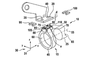
図1にはシステム10が斜視図で示されている。以下の図面においては座標系30を参照することが望ましい。座標系30は右手系として形成されている。座標系30は、x軸(長手方向)、y軸(横方向)およびz軸(高さ)を有している。x軸、y軸およびz軸は、互いに起点31において交差している。座標系30は、もちろん他の形式で形成されていてもよい。座標系30は、以下において、後の図面においてシステム10の構成を特に明瞭に説明するのに用いられる。
FIG. 1 shows the
システム10は、保持装置15、固定部分20およびユニット25を有している。固定部分20は例えば、自動車の一部、特に内燃機関またはボディの一部であってもよい。ユニット25は例えばポンプとして形成されていてもよい。ユニット25は例えば、部分的に円筒形状に形成されていて、保持装置15を用いて固定部分20に結合されている。
The
図2には、図1に示したシステム10が分解図で示されている。
FIG. 2 shows an exploded view of the
固定部分20は、例えば平らに形成されている。固定部分20は、例えばxy平面において延在していて、例えば第1の貫通開口35および第2の貫通開口40を有している。第1の貫通開口35は、長手方向において第2の貫通開口40に対して間隔をおいて配置されている。
The fixed
保持装置15は、緩衝エレメント45および固定エレメント50を有している。緩衝エレメント45は、部分的にリング形状に長手方向軸線55を中心にして延びており、この長手方向軸線55は、好ましくはx軸に対して平行に方向付けられていて、本実施形態では例えばx軸に配置されている。このとき緩衝エレメント45は、第1の収容部60を有している。この第1の収容部60は、円筒形に形成されていて、ユニット25の外周面65に周囲から係合するために用いられる。
The holding
緩衝エレメント45は、さらに第1の接触面70および好ましくは第2の接触面75を有している。この第1の接触面70および第2の接触面75は、緩衝エレメント45の、固定部分20に向けられた側に配置されていて、横方向において例えば互いに間隔をおいて配置されている。第1および第2の接触面70,75で、緩衝エレメント45は固定部分20に接触している。固定部分20はz方向に固定部分厚さdを有している。
The
第1の接触面70と第2の接触面75との間に、緩衝エレメント45は凹部80を有している。この凹部80は第1および/または第2の接触面70,75に対してz方向においてずらされて、固定部分20とは反対の側に配置されている。凹部80は例えば溝形に形成されている。
The
固定エレメント50は、例えば第1の固定ピン85および第2の固定ピン90を有している。第1の固定ピン85は、第1の貫通開口35に対応して配置されている。第2の固定ピン90は第2の貫通開口40に対応して配置されている。固定ピン85,90は各1つの溝105,110を有している。この溝105,110は、システム10の組み立てられていない状態において、z方向において、接触面70,75に対して溝間隔aを有している。
The fixing
保持装置15は、さらに第1の係合エレメント95および例えば第2の係合エレメント100を有している。第1の係合エレメント95および第2の係合エレメント100は、本実施形態では例えば同一に形成されている。係合エレメント95,100は、例えばU字形に形成されている。係合エレメント95,100は、好ましくは材料として金属を有している。
The holding
図3には、システム10を図1に示した断面平面A−Aに沿って断面した断面図が示されている。係合エレメント95,100は、固定部分20の、緩衝エレメント45とは反対の側に配置されている。第1の固定ピン85は、第1の貫通開口35を通して案内され、かつ第2の固定ピン90は、第2の貫通開口40を通して案内されている。第1の係合エレメント95は第1の溝105に係合し、第1の固定ピン85を固定部分20に形状結合によって結合する。第2の係合エレメント100は、固定部分20の、緩衝エレメント45とは反対の側において、第2の溝110に係合し、第2の固定ピン90を固定部分20に形状結合で結合する。
FIG. 3 shows a cross-sectional view of the
係合エレメント95,100のU字形の構成によって、係合エレメント95,100は長手方向において簡単に溝105,110に差し込むことができ、その結果、特に迅速かつ安価に保持装置15を固定部分20に結合させることができる。
Due to the U-shaped configuration of the engaging elements 95,100, the engaging elements 95,100 can be easily inserted into the
特に好ましくは、保持装置15の組み付けられていない状態において、溝間隔aは固定部分20の固定部分厚さdよりも小さい。係合エレメント95,100を組み付けるために、緩衝エレメント45は接触面70,75において圧縮されて予荷重を加えられる。次いで係合エレメント95,100が溝105,110内に挿入される。予荷重は、組み付けられた状態において、溝間隔aが固定部分厚さdよりも小さいという選択によって、少なくとも部分的に維持され、その結果保持装置15は、追加的に摩擦結合によって固定部分20に結合されている。これによって、保持装置15と固定部分20との間における誤差補償を準備することができる。さらに係合エレメント95,100は溝105,110内においてz方向において負荷を加えられ、これによって溝105,110からの係合エレメント95,100の意図しない解離が阻止される。
Particularly preferably, the groove spacing a is smaller than the fixed portion thickness d of the fixed
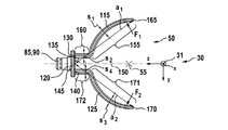
図4には、固定エレメント50が側面図で示されている。この固定エレメント50は、第1の脚115、第1の結合部分120および第2の脚125を有している。第1の脚115はその不動の端部130で、結合部分120の第1の側面135に結合されている。第2の脚125はその不動の端部140で、結合部分120の第1の側面135に結合されている。このとき第1の脚115の不動の端部130は、横方向(y軸方向)において、第2の脚125の不動の端部140に対してずらされて配置されている。長手方向において脚115,125は同じ高さに配置されている。第1の側面135とは反対側に位置している第2の側面145において、固定ピン85,90は結合部分120に結合されている。この結合部分120は、平らに形成されていて、例えばxy平面において延在している。
In FIG. 4, the fixing
第1の脚115と第2の脚125とは、本実施形態では例えば対称平面150を挟んで線対称に形成されている。このとき対称平面150はxy平面において延びている。もちろん第1の脚115は、第2の脚125に対して異なった形式で形成されていてもよい。
In the present embodiment, the
第1の脚115は、第1の部分155と第2の部分160とを有している。このとき第2の部分160は、第1の脚115の不動の端部130に隣接している。このとき第2の部分160は、第1の部分155と結合部分120との間に配置されている。第2の部分160は、平らに形成されていて、例えばxz平面において延在している。第1の部分155は、例えば長手方向軸線55を中心にした円弧に沿って延びている。第1の部分155の他の幾何学的な構成も可能である。第1の部分155は、本実施形態では例えばほぼ四分円を成しているので、第1の脚115の自由端部165は、ほぼ長手方向軸線55の高さにおいて終端している。第1の部分155において、第1の部分155における第1の脚115の第1の厚さs1は、結合部分120からの第1の間隔a1が増大するにしたがって、第1の脚115の自由端部165に向かって減少している。第1の厚さs1は第1の部分155において、次のように、すなわち例えば保持装置15におけるユニット25の組付け時に、少なくとも部分的にyz平面において作用する、第1の脚115に対する第1の力F1の作用時に、第1の曲げ応力S1が第1の部分155の延在長さにわたってほぼ一定であるように選択されている。
The
第2の部分160において、第2の部分160の第2の厚さs2は例えば一定である。また第2の部分160において、結合部分120に向かう第1の間隔a1が増大するにしたがって、第1の脚115の第1の部分155に向かって、第1の脚115の第2の厚さs2は減少していてもよい。これによって第2の部分160においても、負荷が与えられる時における第1の曲げ応力S1を、一定に保つことができる。
In the
第2の脚125は、第3の部分171と第4の部分172とを有している。このとき第4の部分172は、第2の脚125の不動の端部140に隣接している。このとき第4の部分172は、第3の部分171と結合部分120との間に配置されている。第4の部分172は平らに形成されていて、第2の部分160に対して平行に横方向にずらされて延びている。第3の部分171は、例えば長手方向軸線55を中心にした円弧に沿って延びている。第3の部分171の他の幾何学的な構成も可能である。第3の部分171は、本実施形態では例えばほぼ四分円を成しており、第2の脚125の自由端部170はほぼ長手方向軸線55の高さにおいて終端している。これによって脚115,125は、一緒になってほぼ180°の角度範囲を取り囲んでいる。第2の部分160および第4の部分172は、z方向において等しく広幅に形成されている。
The
第3の部分171において、第3の部分171における第2の脚125の第3の厚さs3は、結合部分120からの第2の間隔a2が増大するにしたがって、第2の脚125の自由端部170に向かって減少する。第3の厚さs3は第3の部分171において、次のように、すなわち例えば保持装置15におけるユニット25の組付け時に、少なくとも部分的にyz平面において作用する、第2の脚125に対する第2の力F2の作用時に、第2の曲げ応力S2が、第3の部分171の延在長さにわたってほぼ一定であるように選択されている。
In a
第4の部分172において、第4の部分172の第4の厚さs4は例えば一定である。また第4の部分172において、結合部分120に向かう第2の間隔a2が増大するにしたがって、第2の脚125の第3の部分171に向かって、第2の脚125の第4の厚さs4は減少していてもよい。
In the
脚115,125の上に述べた構成は、力F1,F2の合力によって生じる脚115,125の伸長が、ひいては合力によって生じる固定エレメント50の機械的な応力が、脚115,125全体に分配されていて、脚115,125に対して局部的に作用しないという利点を有している。これによって固定エレメント50の構造全体は、支持力をもって作用し、かつ目標破損箇所が固定エレメント50において回避される。
The configuration described above of the
このことには、ユニット25が確実に固定部分20において固定され、例えばホースの組付け中、特に例えば冷却ホースの組付け中のような、例えば組付け中におけるユニット25の変位、またはユニット25の運転時におけるユニット25の変位が、強く制限されるという利点がある。
This ensures that the
図5には、図4に示した固定エレメント50が斜視図で示されている。第1の脚115は第1の切欠き175を有し、第2の脚125は第2の切欠き180を有している。これらの切欠き175,180は、例えば台形に形成されていて、例えば脚115,125における貫通開口として形成されている。また、切欠きが脚115,125における凹部として形成され、かつ/または両方の脚115,125のうちの一方だけが切欠き175,180を有するような構成も可能である。さらにまた切欠き175,180を省くことも可能である。切欠き175,180は、脚115,125の自由端部165,170に向かって増大する横断面を有している。また切欠き175,180は幾何学的に異なった形式で形成されていてもよい。本実施形態では、第1の脚115の第1の切欠き175と第1の部分155とは、第1の部分155への第1の力F1の導入時に第1の曲げ応力S1が第1の部分155の長さにわたって一定であるように、互いに合わせられている。同様に好ましくは、第2の脚125の第2の切欠き180と第3の部分171とは、第3の部分171への第2の力F2の導入時に第2の曲げ応力S2が第3の部分171の長さにわたって一定であるように、互いに合わせられている。
In FIG. 5, the fixing
本実施形態では、結合部分120、第1の脚115、第2の脚125および固定ピン85,90は、一体にかつ材料均一に形成されている。このとき、固定エレメント50がプラスチック、特にポリアミドを材料として有していると特に有利である。さらに、固定エレメント50が射出成形法を用いて製造されると有利である。
In the present embodiment, the connecting
さらに、本実施形態では固定エレメント50の少なくとも1つの縁部173、好ましくはすべての縁部173が面取り(gebrochen)されている。面取りされた縁部173はこのとき丸み付けされていてもまたは斜め面取り(anfasen)されていてもよい。このような構成には、固定エレメント50を射出成形型から特に容易に離型することができるという利点がある。
Further, in this embodiment, at least one
図6には、緩衝エレメント45が斜視図で示されている。この緩衝エレメント45はほぼリング形に形成されていて、第2の収容部185を有している。この第2の収容部185は、第1の収容部分190、第2の収容部分195および第3の収容部分200を有している。さらに第2の収容部185は、第1の出口開口205および第2の出口開口210を有している。第1の出口開口205および第2の出口開口210は、凹部80に隣接して両接触面70,75の間に配置されている。出口開口205,210は、第2の収容部195に接続されている。
In FIG. 6, the
第1の収容部分190には、第1の脚115が係合する。このとき第1の脚115は第1の収容部分190において第1の収容部分190によって完全に取り囲まれるので、第1の脚115は、緩衝エレメント45の別の材料によって完全に覆われている。第2の収容部分195には、結合部分120が係合している。このとき第2の収容部分195は、本実施形態では結合部分120を完全に取り囲んでいる。第1の出口開口205を通して第1の固定ピン85が案内され、かつ第2の出口開口210を通して第2の固定ピン90が案内されている。第3の収容部分200には第2の脚125が係合しており、このとき第3の収容部分200は第2の脚125を完全に取り囲んでおり、その結果第2の脚125は、緩衝エレメント45の別の材料によって完全に取り囲まれている。
The
このときエラストマが、好ましくは特にエチレン・プロピレン・ジエンゴム(EPDM)を有していると、特に有利である。また保持装置15が2成分射出成形法によって製造されると、特に有利である。さらにまた、固定エレメント50が第1の射出形成法で製造され、第2の射出成形法において挿入体(Einleger)として用いられ、この第2の射出成形法において固定エレメント50の周囲が緩衝エレメント45の別の材料によって射出形成される。これによって保持装置15を、特に安価にかつ簡単に製造することができる。特にこのとき、固定エレメント50と緩衝エレメント45との材料結合による結合のために、固定エレメント50における、時間のかかるプライマの使用を省くことができる。
At this time, it is particularly advantageous that the elastomer preferably has ethylene propylene diene rubber (EPDM). Further, it is particularly advantageous if the holding
本実施形態において、固定エレメント50の材料は、緩衝エレメント45の別の材料よりも低い弾性を有している。これによって振動を、ユニット25と固定部分20との間において緩衝エレメント45によって効果的に減衰すること、および保持装置15を介して固定部分20とユニット25との間において伝達しないことが、保証される。このようにして、ユニット25を低振動で支持すること、かつ他方ではユニット25によって生ぜしめられた振動を、固定部分20に伝達しないことが保証される。
In this embodiment, the material of the fixed
さらに、固定エレメント50における面取りされた縁部173によって、固定エレメント50が緩衝エレメント45の材料に局部的な過負荷を加えることがなくなり、かつこれによって緩衝エレメント45の別の材料の裂けないことが保証される。
Further, the chamfered
切欠き175,180によって、ホルダにおけるユニット25の組付け時に保持装置15に加えられる、固定エレメント50の伸長が、局部的に作用するのではなく、伸長が脚115,125全体に分配されることが保証される。これは、固定エレメント50の負荷耐性を高め、かつ保持装置15のエラーのない機能のために役立つ。さらに切欠き175,180は、緩衝エレメント45との形状結合による結合部を提供し、これによって、脚115,125と緩衝エレメント45との間におけるすべての表面における剪断応力を低減させる。
The notches 175,180 distribute the extension of the fixing
図7は、図4および図5に示した固定エレメント50の別の実施形態を示す斜視図である。固定エレメント50は、例えば第1の補強リブ215と例えば第2の補強リブ220とを有している。補強リブ215,220は、結合部分120の第1の側面135に配置されている。補強リブ215,220は、長手方向(x軸)において例えば長手方向軸線55に対して平行に延びている。本実施形態では第1の補強リブ215は、第1の脚115の第2の部分160に結合されている。さらに第2の補強リブ220は、長手方向において第2の脚125の第2の部分160に結合されている。このとき特に有利には、補強リブ215,220は、結合部分120の最大長さIの少なくとも80%にわたって延在している。この構成には、結合部分120の抵抗モーメントが高められ、その結果機械的な負荷が与えられる時にも結合部分120が歪みなしにかつ平らなままであるという利点がある。これによって、例えば固定エレメント50の射出成形時における熱応力に基づく、平面からの結合部分120の屈曲が回避される。これにより、第1の固定ピン85が第2の固定ピン90に対して平行にz方向に方向付けられることが保証されている。
FIG. 7 is a perspective view showing another embodiment of the fixing
これによって固定ピン85,90を固定部分20における保持装置15の組付け時に、貫通開口35,40を通して案内できることを、確実に保証することができる。さらに、固定ピン85,90が運転状態において片側において押圧され、固定エレメント50が早期に機械的に故障することが、回避される。
This makes it possible to reliably guarantee that the fixing pins 85 and 90 can be guided through the through
図8には、図7において説明した固定エレメント50の別の実施形態が斜視図で示されている。この実施形態では、ただ1つの補強リブ215だけが設けられている。この補強リブ215は、横方向において第1の脚115と第2の脚125との間に配置されており、かつ結合部分120のほぼ全長にわたって延在している。
FIG. 8 shows another embodiment of the fixed
さらに付言すると、図1〜図8に示した特徴は互いに組み合わせることができ、かつ/または幾つかの特徴を省くことが可能である。 Further, the features shown in FIGS. 1-8 can be combined with each other and / or some features can be omitted.
Claims (24)
緩衝エレメント(45)と、該緩衝エレメント(45)に結合された固定エレメント(50)とを備え、
前記緩衝エレメント(45)は、前記ユニット(25)に結合可能であり、
前記固定エレメント(50)は、少なくとも1つの脚(115,125)と、該脚(115,125)に結合された結合部分(120)とを有し、
前記脚(115,125)は、前記緩衝エレメント(45)の収容部(60,185)内に配置されており、前記緩衝エレメント(45)を少なくとも部分的に補強するように形成されており、
前記結合部分(120)は前記自動車(20)に結合可能であり、
前記結合部分(120)に対する間隔(a1,a2)が増大するにしたがって、前記脚(115,125)の厚さ(s1,s2,s3,s4)が減少している
ことを特徴とする、ユニット(25)を自動車(20)に固定するための保持装置(15)。 A holding device (15) for fixing the unit (25) to the automobile (20).
A buffer element (45) and a fixed element (50) coupled to the buffer element (45) are provided.
The buffer element (45) can be coupled to the unit (25).
The fixed element (50) has at least one leg (115, 125) and a coupling portion (120) attached to the leg (115, 125).
The legs (115, 125) are arranged within the accommodating portion (60, 185) of the cushioning element (45) and are formed to at least partially reinforce the cushioning element (45).
The coupling portion (120) can be coupled to the automobile (20).
The thickness (s 1 , s 2 , s 3 , s 4 ) of the legs (115, 125) decreases as the distance (a 1 , a 2 ) with respect to the connecting portion (120) increases. A holding device (15) for fixing the unit (25) to the automobile (20).
請求項1記載の保持装置(15)。 The thickness (s 1 , s 2 , s 3 , s 4 ) of the legs (115, 125) is at least partially the introduction of forces (F 1 , F 2) onto the legs (115, 125). Sometimes the bending stresses (S 1 , S 2 ) are chosen to be constant over at least one portion (155,171) of the legs (115, 125).
The holding device (15) according to claim 1.
該別の脚(125)は、前記結合部分(120)に結合されており、
該結合部分(120)は、前記脚(115)と前記別の脚(125)との間に配置されており、
前記結合部分(120)に対する前記別の脚(125)の間隔が増大するにしたがって、前記別の脚(125)の厚さ(s3,s4)が減少する、
請求項1または2記載の保持装置(15)。 The fixed element (50) has one separate leg (125).
The other leg (125) is attached to the connecting portion (120).
The connecting portion (120) is arranged between the leg (115) and the other leg (125).
As the distance between the other leg (125) with respect to the connecting portion (120) increases, the thickness (s 3 , s 4 ) of the other leg (125) decreases.
The holding device (15) according to claim 1 or 2.
請求項3記載の保持装置(15)。 The joint portion (120), the leg (115) and the other leg (125) are integrally and materially uniformly formed, and the fixing element (50) has at least plastic as a material.
The holding device (15) according to claim 3.
請求項4記載の保持装置(15)。 The plastic is polyamide.
The holding device (15) according to claim 4.
請求項3から5までのいずれか1項記載の保持装置(15)。 The buffer element (45) has a material different from that of the polyamide.
The holding device (15) according to any one of claims 3 to 5.
請求項6記載の保持装置(15)。 The other material has an elastomer,
The holding device (15) according to claim 6.
請求項3から7までのいずれか1項記載の保持装置(15)。 The material of the fixed element (50) has lower elasticity than the material of the cushioning element (45).
The holding device (15) according to any one of claims 3 to 7.
請求項3から8までのいずれか1項記載の保持装置(15)。 The holding device (15) is manufactured by using an injection molding method.
The holding device (15) according to any one of claims 3 to 8.
請求項3から9までのいずれか1項記載の保持装置(15)。 The holding device (15) is manufactured by using a two-component injection molding method.
The holding device (15) according to any one of claims 3 to 9.
前記脚(115,125)は、第1の部分(155,171)を有し、
該第1の部分(155,171)は、前記長手方向軸線(55)を中心にして円軌道に沿って延びている、
請求項1から10までのいずれか1項記載の保持装置(15)。 The cushioning element (45) extends in a ring shape about the longitudinal axis (55).
The legs (115,125) have a first portion (155,171) and
The first portion (155, 171) extends along a circular orbit about the longitudinal axis (55).
The holding device (15) according to any one of claims 1 to 10.
該第2の部分(160,172)は、平らに形成されており、
前記第2の部分(160,172)は、前記第1の部分(155,171)および前記結合部分(120)に結合されていて、前記第1の部分(155,171)と前記結合部分(120)との間に配置されている、請求項11記載の保持装置(15)。 The legs (115,125) have a second portion (160,172).
The second part (160,172) is formed flat and
The second portion (160,172) is coupled to the first portion (155,171) and the coupling portion (120), and the first portion (155,171) and the coupling portion (155,171) are bonded to the first portion (155,171) and the coupling portion (120). 120) The holding device (15) according to claim 11, which is arranged between the holding device and the device.
前記切欠き(175,180)は、前記脚(115,125)の自由端部(165,170)に向かって増大する横断面を有している、
請求項1から12までのいずれか1項記載の保持装置(15)。 The legs (115,125) have notches (175,180) and
The notch (175,180) has a cross section that increases towards the free end (165,170) of the leg (115,125).
The holding device (15) according to any one of claims 1 to 12.
請求項13記載の保持装置(15)。 The notch (175,180) is formed in a trapezoidal shape.
13. The holding device (15) according to claim 13.
前記収容部分(190,195,200)は、前記脚(115,125)に対応するように形成されており、
前記収容部分(190,195,200)は、前記脚(115,125)を完全に取り囲んでいる、
請求項1から14までのいずれか1項記載の保持装置(15)。 Said damping element (45) has the receiving portion having a receiving portion (190,195,200) and (60,185),
The accommodating portion (190,195,200) is formed so as to correspond to the leg (115,125).
The containment portion (190,195,200) completely surrounds the leg (115,125).
The holding device (15) according to any one of claims 1 to 14.
前記脚(115,125)は、第1の側面(135)において前記結合部分(120)に結合されており、
前記第1の側面(135)において前記固定エレメント(50)は、補強リブ(215,220)を有し、
該補強リブ(215,220)は、前記結合部分(120)に結合されている、
請求項1から15までのいずれか1項記載の保持装置(15)。 The joint portion (120) is formed flat and has a flat shape.
The legs (115, 125) are joined to the connecting portion (120) on the first side surface (135).
On the first side surface (135), the fixing element (50) has reinforcing ribs (215, 220).
The reinforcing ribs (215, 220) are coupled to the connecting portion (120).
The holding device (15) according to any one of claims 1 to 15.
請求項16記載の保持装置(15)。 The reinforcing ribs (215,220) extend over at least 80% of the maximum length of the joint portion (120).
16. The holding device (15) according to claim 16.
請求項12を引用する請求項16または17記載の保持装置(15)。 The reinforcing ribs (215,220) are coupled to the second portion (160,172).
The holding device (15) according to claim 16 or 17, which cites claim 12.
前記補強リブ(215,220)は、横方向において前記脚(115)と前記別の脚(125)との間に配置されている、請求項16から18までのいずれか1項記載の保持装置(15)。 The fixed element (50) has one separate leg (125).
The holding device according to any one of claims 16 to 18, wherein the reinforcing ribs (215, 220) are arranged laterally between the leg (115) and the other leg (125). (15).
該固定ピン(85,90)は、前記結合部分(120)に結合されており、
前記緩衝エレメント(45)は、第1の接触面(70)と、該第1の接触面(70)に対して間隔をおいて配置された第2の接触面(75)とを有し、
前記第1の接触面(70)と前記第2の接触面(75)との間に、固定ピン(85,90)が配置されている、
請求項1から19までのいずれか1項記載の保持装置(15)。 The fixing element (50) has at least one fixing pin (85, 90).
The fixing pin (85, 90) is coupled to the coupling portion (120).
The cushioning element (45) has a first contact surface (70) and a second contact surface (75) spaced apart from the first contact surface (70).
Fixing pins (85, 90) are arranged between the first contact surface (70) and the second contact surface (75).
The holding device (15) according to any one of claims 1 to 19.
前記固定ピン(85,90)は、前記自動車の固定部分(20)を貫通して係合するように形成されており、
前記係合エレメント(95,100)は、前記固定部分(20)の、前記緩衝エレメント(45)とは反対の側に配置されていて、前記固定ピン(85,90)を前記固定部分(20)において固定するために、前記溝(105,110)に係合しており、
該溝(105,110)と前記第1及び前記第2の接触面(70,75)との間の間隔が、前記固定部分(20)の厚さ(d)よりも小さい、
請求項20記載の保持装置(15)。 Engagement elements (95,100) are provided, said fixing pins (85,90) having grooves (105,110).
The fixing pins (85, 90) are formed so as to penetrate and engage with the fixing portion (20) of the automobile.
The engaging element (95, 100) is arranged on the side of the fixing portion (20) opposite to the buffer element (45), and the fixing pin (85, 90) is attached to the fixing portion (20). ), It is engaged with the groove (105, 110) and is engaged with the groove (105, 110).
The distance between the groove (105,110) and the first and second contact surfaces (70,75) is smaller than the thickness (d) of the fixed portion (20).
The holding device (15) according to claim 20.
請求項1から21までのいずれか1項記載の保持装置(15)。 The fixed element (50) has at least one chamfered edge.
The holding device (15) according to any one of claims 1 to 21.
Applications Claiming Priority (2)
| Application Number | Priority Date | Filing Date | Title |
|---|---|---|---|
| DE102016201560.5 | 2016-02-02 | ||
| DE102016201560.5A DE102016201560B4 (en) | 2016-02-02 | 2016-02-02 | Bracket for attaching a unit, in particular a pump, to a motor vehicle |
Publications (2)
| Publication Number | Publication Date |
|---|---|
| JP2017161068A JP2017161068A (en) | 2017-09-14 |
| JP6851209B2 true JP6851209B2 (en) | 2021-03-31 |
Family
ID=57821852
Family Applications (1)
| Application Number | Title | Priority Date | Filing Date |
|---|---|---|---|
| JP2017017573A Active JP6851209B2 (en) | 2016-02-02 | 2017-02-02 | Holding device for fixing the unit, especially the pump, to the car |
Country Status (5)
| Country | Link |
|---|---|
| US (1) | US9994161B2 (en) |
| EP (1) | EP3203104B1 (en) |
| JP (1) | JP6851209B2 (en) |
| CN (1) | CN107131412B (en) |
| DE (1) | DE102016201560B4 (en) |
Families Citing this family (8)
| Publication number | Priority date | Publication date | Assignee | Title |
|---|---|---|---|---|
| DE102016209204A1 (en) * | 2016-05-27 | 2017-11-30 | Robert Bosch Gmbh | Device for controlling at least one fluid flow in a vehicle |
| US10131222B1 (en) * | 2017-05-05 | 2018-11-20 | Toyota Motor Engineering & Manufacturing North America, Inc. | Snorkel roof drip attachment |
| JP6499734B2 (en) | 2017-08-24 | 2019-04-10 | ファナック株式会社 | Mounting structure and cooling fan |
| EP3785961B1 (en) * | 2019-08-26 | 2025-10-15 | Vibracoustic Nantes SAS | Bracket for supporting an electric motor and method for manufacturing such a bracket |
| US12184152B1 (en) * | 2021-01-11 | 2024-12-31 | Hydro-Gear Limited Partnership | Vibration damping apparatus for mounting an electric actuator on a hydraulic drive |
| FR3119568B1 (en) * | 2021-02-11 | 2025-02-28 | Psa Automobiles Sa | PUMP SUPPORT AND HEAT SHIELD ASSEMBLY FOR A HEAT ENGINE |
| DE102021106098B3 (en) * | 2021-03-12 | 2022-05-25 | Bühler Motor GmbH | Bracket for attaching a pump |
| US20250163938A1 (en) * | 2022-04-04 | 2025-05-22 | Aisin Corporation | Electric pump |
Family Cites Families (23)
| Publication number | Priority date | Publication date | Assignee | Title |
|---|---|---|---|---|
| US3012743A (en) * | 1959-10-05 | 1961-12-12 | Jenkins Orville | Motor mounting ring |
| FR2274737A1 (en) | 1974-06-13 | 1976-01-09 | Kleber Colombes | SHOCK ABSORBER FOR BORING FENDERS |
| DE2933586C2 (en) | 1979-08-18 | 1982-11-18 | Goetze Ag, 5093 Burscheid | Vibration absorber for rotating shafts |
| JPH081230B2 (en) | 1986-05-21 | 1996-01-10 | スズキ株式会社 | Elastic support |
| SE467635B (en) | 1988-09-30 | 1992-08-17 | Electrolux Ab | Vibration damper in motor saw |
| JPH051666Y2 (en) * | 1989-02-20 | 1993-01-18 | ||
| US5113104A (en) * | 1989-10-19 | 1992-05-12 | General Electric Company | Structured product dynamoelectric machine |
| US5397950A (en) * | 1993-12-23 | 1995-03-14 | Cary Products Co., Inc. | Isolation motor mount and gasket |
| ES2115114T3 (en) * | 1994-08-08 | 1998-06-16 | Siemens Ag | SOUNDPROOFING FIXING DEVICE FOR MOTORS, ESPECIALLY FOR ELECTRIC CONTROLLER DRIVES IN MOTORIZED VEHICLES. |
| DE19713461C2 (en) | 1996-03-20 | 1999-02-11 | Henniges Elastomer Kunststoff | Elastomeric spring element |
| JPH11241744A (en) * | 1998-02-26 | 1999-09-07 | Mitsubishi Eng Plast Corp | Resin spring and resin spring assembly |
| JP2002181101A (en) * | 2000-12-18 | 2002-06-26 | Maruyasu Industries Co Ltd | Bracket ring |
| JP2004242478A (en) * | 2003-02-10 | 2004-08-26 | Nippon Pop Rivets & Fasteners Ltd | Cable clamp |
| US20050023912A1 (en) * | 2003-07-28 | 2005-02-03 | A.O. Smith Corporation | Electric motor for hydromassage bathtubs |
| DE202004017501U1 (en) * | 2004-11-11 | 2005-01-05 | Kirchhoff Gmbh & Co.Kg | Device for connecting two exhaust pipes leading off |
| US20070035073A1 (en) * | 2005-08-10 | 2007-02-15 | Kinmartin Jeffrey C | Isolation for electric motor |
| JP5074935B2 (en) * | 2008-01-21 | 2012-11-14 | 日本電産セイミツ株式会社 | Vibration motor |
| DE102009029067A1 (en) * | 2009-09-01 | 2011-03-03 | Robert Bosch Gmbh | Holder for mounting an aggregate |
| US8714943B2 (en) * | 2010-09-29 | 2014-05-06 | Halla Visteon Climate Control Corporation | Mounting and damping system for a compressor |
| DE102011085558A1 (en) | 2011-11-02 | 2013-05-02 | Robert Bosch Gmbh | Holder for fixing an aggregate, in particular a pump, to a motor vehicle |
| JP5836781B2 (en) * | 2011-12-06 | 2015-12-24 | 株式会社ブリヂストン | Vibration isolator |
| JP5967800B2 (en) * | 2012-01-31 | 2016-08-10 | ミネベア株式会社 | Motor having a holder for flexible printed circuit board and actuator using the motor |
| KR101339261B1 (en) * | 2012-10-16 | 2013-12-09 | 기아자동차 주식회사 | Transmission mounting unit for vehicle |
-
2016
- 2016-02-02 DE DE102016201560.5A patent/DE102016201560B4/en not_active Expired - Fee Related
- 2016-05-26 US US15/165,229 patent/US9994161B2/en active Active
-
2017
- 2017-01-16 EP EP17151583.6A patent/EP3203104B1/en active Active
- 2017-01-26 CN CN201710349987.1A patent/CN107131412B/en active Active
- 2017-02-02 JP JP2017017573A patent/JP6851209B2/en active Active
Also Published As
| Publication number | Publication date |
|---|---|
| EP3203104B1 (en) | 2021-12-08 |
| US9994161B2 (en) | 2018-06-12 |
| JP2017161068A (en) | 2017-09-14 |
| CN107131412A (en) | 2017-09-05 |
| US20170217380A1 (en) | 2017-08-03 |
| DE102016201560A1 (en) | 2017-08-03 |
| EP3203104A1 (en) | 2017-08-09 |
| CN107131412B (en) | 2021-08-03 |
| DE102016201560B4 (en) | 2024-02-01 |
Similar Documents
| Publication | Publication Date | Title |
|---|---|---|
| JP6851209B2 (en) | Holding device for fixing the unit, especially the pump, to the car | |
| US9296923B2 (en) | Method for establishing an adhesive connection between at least two components, in particular vehicle body components, by use of positive-fit elements | |
| US9441705B2 (en) | Holder for fastening a unit, in particular a pump, to a motor vehicle | |
| CN105051382B (en) | Connecting device | |
| US9551396B2 (en) | Vibration damping device | |
| US9885410B2 (en) | Unit support | |
| US10022938B2 (en) | Plastic component | |
| US9453594B2 (en) | Fixing device | |
| CN106050855B (en) | Fixing piece | |
| CN111216614B (en) | Vehicle carpet and mat fixing device and installation method thereof | |
| CN117863860A (en) | Engine mounts | |
| JP2018123859A (en) | Vibration-isolating device with fastening member | |
| JP2011247296A (en) | Fixing device | |
| CN103443483A (en) | Thread-reinforced axial coupling | |
| US20250128593A1 (en) | Snap connection, motor vehicle structure and motor vehicle | |
| CN104937288B (en) | Connectors for motor vehicles | |
| JP7602979B2 (en) | Anti-vibration device | |
| CN114364900A (en) | Damping device and mounting method thereof | |
| CN110552937B (en) | Connecting assembly comprising a connecting piece and at least two carrier pieces | |
| US10677139B2 (en) | Holding device for an exhaust system | |
| CN114251397B (en) | Torque rod | |
| EP3306130B1 (en) | Vibration-damping device | |
| JP5707113B2 (en) | Vibration isolator | |
| CN223578411U (en) | Mounting components for power units | |
| JP2025123211A (en) | Block device |
Legal Events
| Date | Code | Title | Description |
|---|---|---|---|
| A521 | Request for written amendment filed |
Free format text: JAPANESE INTERMEDIATE CODE: A523 Effective date: 20170412 |
|
| A621 | Written request for application examination |
Free format text: JAPANESE INTERMEDIATE CODE: A621 Effective date: 20191106 |
|
| A977 | Report on retrieval |
Free format text: JAPANESE INTERMEDIATE CODE: A971007 Effective date: 20200722 |
|
| A131 | Notification of reasons for refusal |
Free format text: JAPANESE INTERMEDIATE CODE: A131 Effective date: 20200928 |
|
| A521 | Request for written amendment filed |
Free format text: JAPANESE INTERMEDIATE CODE: A523 Effective date: 20201222 |
|
| TRDD | Decision of grant or rejection written | ||
| A01 | Written decision to grant a patent or to grant a registration (utility model) |
Free format text: JAPANESE INTERMEDIATE CODE: A01 Effective date: 20210208 |
|
| A61 | First payment of annual fees (during grant procedure) |
Free format text: JAPANESE INTERMEDIATE CODE: A61 Effective date: 20210309 |
|
| R150 | Certificate of patent or registration of utility model |
Ref document number: 6851209 Country of ref document: JP Free format text: JAPANESE INTERMEDIATE CODE: R150 |
|
| R250 | Receipt of annual fees |
Free format text: JAPANESE INTERMEDIATE CODE: R250 |
|
| R250 | Receipt of annual fees |
Free format text: JAPANESE INTERMEDIATE CODE: R250 |
|
| R250 | Receipt of annual fees |
Free format text: JAPANESE INTERMEDIATE CODE: R250 |