JP6855100B2 - 単一流路構造 - Google Patents
単一流路構造 Download PDFInfo
- Publication number
- JP6855100B2 JP6855100B2 JP2019540592A JP2019540592A JP6855100B2 JP 6855100 B2 JP6855100 B2 JP 6855100B2 JP 2019540592 A JP2019540592 A JP 2019540592A JP 2019540592 A JP2019540592 A JP 2019540592A JP 6855100 B2 JP6855100 B2 JP 6855100B2
- Authority
- JP
- Japan
- Prior art keywords
- wall
- turbine
- flow path
- combustor
- band
- Prior art date
- Legal status (The legal status is an assumption and is not a legal conclusion. Google has not performed a legal analysis and makes no representation as to the accuracy of the status listed.)
- Active
Links
Images




Classifications
-
- F—MECHANICAL ENGINEERING; LIGHTING; HEATING; WEAPONS; BLASTING
- F23—COMBUSTION APPARATUS; COMBUSTION PROCESSES
- F23R—GENERATING COMBUSTION PRODUCTS OF HIGH PRESSURE OR HIGH VELOCITY, e.g. GAS-TURBINE COMBUSTION CHAMBERS
- F23R3/00—Continuous combustion chambers using liquid or gaseous fuel
- F23R3/002—Wall structures
-
- F—MECHANICAL ENGINEERING; LIGHTING; HEATING; WEAPONS; BLASTING
- F01—MACHINES OR ENGINES IN GENERAL; ENGINE PLANTS IN GENERAL; STEAM ENGINES
- F01D—NON-POSITIVE DISPLACEMENT MACHINES OR ENGINES, e.g. STEAM TURBINES
- F01D25/00—Component parts, details, or accessories, not provided for in, or of interest apart from, other groups
- F01D25/24—Casings; Casing parts, e.g. diaphragms, casing fastenings
- F01D25/246—Fastening of diaphragms or stator-rings
-
- F—MECHANICAL ENGINEERING; LIGHTING; HEATING; WEAPONS; BLASTING
- F01—MACHINES OR ENGINES IN GENERAL; ENGINE PLANTS IN GENERAL; STEAM ENGINES
- F01D—NON-POSITIVE DISPLACEMENT MACHINES OR ENGINES, e.g. STEAM TURBINES
- F01D5/00—Blades; Blade-carrying members; Heating, heat-insulating, cooling or antivibration means on the blades or the members
- F01D5/02—Blade-carrying members, e.g. rotors
- F01D5/06—Rotors for more than one axial stage, e.g. of drum or multiple disc type; Details thereof, e.g. shafts, shaft connections
-
- F—MECHANICAL ENGINEERING; LIGHTING; HEATING; WEAPONS; BLASTING
- F01—MACHINES OR ENGINES IN GENERAL; ENGINE PLANTS IN GENERAL; STEAM ENGINES
- F01D—NON-POSITIVE DISPLACEMENT MACHINES OR ENGINES, e.g. STEAM TURBINES
- F01D5/00—Blades; Blade-carrying members; Heating, heat-insulating, cooling or antivibration means on the blades or the members
- F01D5/12—Blades
- F01D5/22—Blade-to-blade connections, e.g. for damping vibrations
- F01D5/225—Blade-to-blade connections, e.g. for damping vibrations by shrouding
-
- F—MECHANICAL ENGINEERING; LIGHTING; HEATING; WEAPONS; BLASTING
- F01—MACHINES OR ENGINES IN GENERAL; ENGINE PLANTS IN GENERAL; STEAM ENGINES
- F01D—NON-POSITIVE DISPLACEMENT MACHINES OR ENGINES, e.g. STEAM TURBINES
- F01D9/00—Stators
- F01D9/02—Nozzles; Nozzle boxes; Stator blades; Guide conduits, e.g. individual nozzles
- F01D9/023—Transition ducts between combustor cans and first stage of the turbine in gas-turbine engines; their cooling or sealings
-
- F—MECHANICAL ENGINEERING; LIGHTING; HEATING; WEAPONS; BLASTING
- F01—MACHINES OR ENGINES IN GENERAL; ENGINE PLANTS IN GENERAL; STEAM ENGINES
- F01D—NON-POSITIVE DISPLACEMENT MACHINES OR ENGINES, e.g. STEAM TURBINES
- F01D9/00—Stators
- F01D9/02—Nozzles; Nozzle boxes; Stator blades; Guide conduits, e.g. individual nozzles
- F01D9/04—Nozzles; Nozzle boxes; Stator blades; Guide conduits, e.g. individual nozzles forming ring or sector
-
- F—MECHANICAL ENGINEERING; LIGHTING; HEATING; WEAPONS; BLASTING
- F02—COMBUSTION ENGINES; HOT-GAS OR COMBUSTION-PRODUCT ENGINE PLANTS
- F02C—GAS-TURBINE PLANTS; AIR INTAKES FOR JET-PROPULSION PLANTS; CONTROLLING FUEL SUPPLY IN AIR-BREATHING JET-PROPULSION PLANTS
- F02C3/00—Gas-turbine plants characterised by the use of combustion products as the working fluid
- F02C3/14—Gas-turbine plants characterised by the use of combustion products as the working fluid characterised by the arrangement of the combustion chamber in the plant
-
- F—MECHANICAL ENGINEERING; LIGHTING; HEATING; WEAPONS; BLASTING
- F02—COMBUSTION ENGINES; HOT-GAS OR COMBUSTION-PRODUCT ENGINE PLANTS
- F02C—GAS-TURBINE PLANTS; AIR INTAKES FOR JET-PROPULSION PLANTS; CONTROLLING FUEL SUPPLY IN AIR-BREATHING JET-PROPULSION PLANTS
- F02C7/00—Features, components parts, details or accessories, not provided for in, or of interest apart form groups F02C1/00 - F02C6/00; Air intakes for jet-propulsion plants
- F02C7/22—Fuel supply systems
-
- F—MECHANICAL ENGINEERING; LIGHTING; HEATING; WEAPONS; BLASTING
- F05—INDEXING SCHEMES RELATING TO ENGINES OR PUMPS IN VARIOUS SUBCLASSES OF CLASSES F01-F04
- F05D—INDEXING SCHEME FOR ASPECTS RELATING TO NON-POSITIVE-DISPLACEMENT MACHINES OR ENGINES, GAS-TURBINES OR JET-PROPULSION PLANTS
- F05D2220/00—Application
- F05D2220/30—Application in turbines
- F05D2220/32—Application in turbines in gas turbines
-
- F—MECHANICAL ENGINEERING; LIGHTING; HEATING; WEAPONS; BLASTING
- F05—INDEXING SCHEMES RELATING TO ENGINES OR PUMPS IN VARIOUS SUBCLASSES OF CLASSES F01-F04
- F05D—INDEXING SCHEME FOR ASPECTS RELATING TO NON-POSITIVE-DISPLACEMENT MACHINES OR ENGINES, GAS-TURBINES OR JET-PROPULSION PLANTS
- F05D2230/00—Manufacture
- F05D2230/50—Building or constructing in particular ways
- F05D2230/53—Building or constructing in particular ways by integrally manufacturing a component, e.g. by milling from a billet or one piece construction
-
- F—MECHANICAL ENGINEERING; LIGHTING; HEATING; WEAPONS; BLASTING
- F05—INDEXING SCHEMES RELATING TO ENGINES OR PUMPS IN VARIOUS SUBCLASSES OF CLASSES F01-F04
- F05D—INDEXING SCHEME FOR ASPECTS RELATING TO NON-POSITIVE-DISPLACEMENT MACHINES OR ENGINES, GAS-TURBINES OR JET-PROPULSION PLANTS
- F05D2240/00—Components
- F05D2240/35—Combustors or associated equipment
-
- F—MECHANICAL ENGINEERING; LIGHTING; HEATING; WEAPONS; BLASTING
- F05—INDEXING SCHEMES RELATING TO ENGINES OR PUMPS IN VARIOUS SUBCLASSES OF CLASSES F01-F04
- F05D—INDEXING SCHEME FOR ASPECTS RELATING TO NON-POSITIVE-DISPLACEMENT MACHINES OR ENGINES, GAS-TURBINES OR JET-PROPULSION PLANTS
- F05D2300/00—Materials; Properties thereof
- F05D2300/60—Properties or characteristics given to material by treatment or manufacturing
- F05D2300/603—Composites; e.g. fibre-reinforced
- F05D2300/6033—Ceramic matrix composites [CMC]
-
- F—MECHANICAL ENGINEERING; LIGHTING; HEATING; WEAPONS; BLASTING
- F23—COMBUSTION APPARATUS; COMBUSTION PROCESSES
- F23R—GENERATING COMBUSTION PRODUCTS OF HIGH PRESSURE OR HIGH VELOCITY, e.g. GAS-TURBINE COMBUSTION CHAMBERS
- F23R2900/00—Special features of, or arrangements for continuous combustion chambers; Combustion processes therefor
- F23R2900/00018—Manufacturing combustion chamber liners or subparts
-
- Y—GENERAL TAGGING OF NEW TECHNOLOGICAL DEVELOPMENTS; GENERAL TAGGING OF CROSS-SECTIONAL TECHNOLOGIES SPANNING OVER SEVERAL SECTIONS OF THE IPC; TECHNICAL SUBJECTS COVERED BY FORMER USPC CROSS-REFERENCE ART COLLECTIONS [XRACs] AND DIGESTS
- Y02—TECHNOLOGIES OR APPLICATIONS FOR MITIGATION OR ADAPTATION AGAINST CLIMATE CHANGE
- Y02T—CLIMATE CHANGE MITIGATION TECHNOLOGIES RELATED TO TRANSPORTATION
- Y02T50/00—Aeronautics or air transport
- Y02T50/60—Efficient propulsion technologies, e.g. for aircraft
Landscapes
- Engineering & Computer Science (AREA)
- Mechanical Engineering (AREA)
- General Engineering & Computer Science (AREA)
- Chemical & Material Sciences (AREA)
- Combustion & Propulsion (AREA)
- Turbine Rotor Nozzle Sealing (AREA)
Description
ガスタービンエンジンの流路の外壁であって、
前記ガスタービンエンジンの燃焼区域を通じて延びる燃焼器部分と、
前記ガスタービンエンジンのタービン区域の少なくとも第1のタービン段を通じて延びるタービン部分と
を備え、
前記燃焼器部分と前記タービン部分とは、前記燃焼器部分と前記タービン部分とが1つだけの単一構造となるように一体に形成され、
前記単一構造は前記流路の外側境界を画定する、外壁。
前記燃焼器部分は、前記燃焼区域の燃焼器の外側ライナを備え、前記タービン部分は、
前記第1のタービン段のノズル部分の外側バンドと、
前記第1のタービン段のブレード部分のシュラウドと、
第2のタービン段のノズル部分の外側バンドと、
前記第2のタービン段のブレード部分のシュラウドと
を備える、任意の前項に記載の外壁。
前記燃焼器部分は、前記燃焼器の前方端にわたって延びる燃焼器ドームと、前記燃焼器の内側ライナとをさらに備え、前記タービン部分は、前記第1のタービン段のノズル部分の内側バンドをさらに備える、任意の前項に記載の外壁。
前記タービン部分は、前記第1のタービン段のノズル部分内に複数のノズル翼をさらに備える、任意の前項に記載の外壁。
前記第1のタービン段の前記外側バンドおよび前記シュラウドは前記ガスタービンエンジンの軸方向中心線に向かって収束し、前記第2のタービン段の前記外側バンドおよび前記シュラウドは前記軸方向中心線から離れるように発散する、任意の前項に記載の外壁。
前記燃焼器部分と前記タービン部分とは、前記単一構造がセラミックマトリックス複合材構成要素であるようにセラミックマトリックス複合材料から一体に形成される、任意の前項に記載の外壁。
ガスタービンエンジンのための流路組立体であって、
前記ガスタービンエンジンの燃焼区域の燃焼器の前方端に位置決めされる燃焼器ドームと、
前記燃焼器ドームから前記ガスタービンエンジンのタービン区域の少なくとも第1のタービン段を通じて延びる外壁と、
前記燃焼器ドームから少なくとも前記燃焼区域を通じて延びる内壁と
を備え、
前記燃焼器ドームは前記外壁から前記内壁へと径方向に延び、
前記燃焼器ドーム、前記外壁、および前記内壁は、前記燃焼器ドーム、前記外壁、および前記内壁が1つだけの単一構造となるように一体に形成される、流路組立体。
前記単一構造は概して環状の流路を画定する、任意の前項に記載の流路組立体。
前記燃焼器ドームは、燃料ノズル組立体の受け入れのための開口を画定する、任意の前項に記載の流路組立体。
前記外壁は、前記タービン区域の前記第1のタービン段と少なくとも第2のタービン段とを通じて延び、前記ガス流路組立体は、前記タービン区域の前記第1の段のノズル部分内において前記内壁から前記外壁へと延びる複数のノズル翼をさらに備え、前記燃焼器ドーム、前記外壁、前記内壁、および前記ノズル翼は、前記燃焼器ドーム、前記外壁、前記内壁、および前記ノズル翼が1つだけの単一構造となるように一体に形成される、任意の前項に記載の流路組立体。
前記単一構造は、複数のあらかじめ含浸させられたセラミックマトリックス複合材テープから形成される、任意の前項に記載の流路組立体。
前記単一構造は炭化ケイ素繊維の生地から形成される、任意の前項に記載の流路組立体。
燃焼区域と、
前記燃焼区域のすぐ下流に位置決めされる第1のタービン段、および、前記第1のタービン段のすぐ下流に位置決めされる第2のタービン段を含むタービン区域と
を備えるタービンエンジンであって、
前記燃焼区域および前記タービン区域は流路を定め、
前記燃焼区域は、前記燃焼区域を通る前記流路の外側境界を定める外側ライナを含み、
前記第1のタービン段および前記第2のタービン段の各々はノズル部分とブレード部分とを含み、各々のノズル部分は、前記ノズル部分を通る前記流路の外側境界を定める外側バンドを備え、各々のブレード部分は、前記ブレード部分を通る前記流路の外側境界を定めるシュラウドを備え、
前記外側ライナ、前記外側バンド、および前記シュラウドは、前記外側ライナ、前記外側バンド、および前記シュラウドが1つだけの単一構造となるように一体に形成される、ガスタービンエンジン。
一体にされた前記外側ライナ、前記外側バンド、および前記シュラウドによって形成される前記単一構造は前記流路の単一の外壁であり、前記単一の外壁は、前記燃焼区域、前記第1のタービン段、および前記第2のタービン段を通る前記流路の単一の外側境界を定める、任意の前項に記載のガスタービンエンジン。
前記燃焼区域は、前記燃焼区域を通る前記流路の内側境界を定める内側ライナをさらに備え、前記内側ライナは、前記内側ライナが前記単一構造の一部分となるように、前記外側ライナ、前記外側バンド、および前記シュラウドと一体に形成される、任意の前項に記載のガスタービンエンジン。
各々のノズル部分は、前記ノズル部分を通る前記流路の内側境界を定める内側バンドをさらに備え、前記第1のタービン段のノズル部分の前記内側バンドは、前記第1のタービン段のノズル部分の前記内側バンドが前記単一構造の一部分となるように、前記内側ライナ、前記外側ライナ、前記外側バンド、および前記シュラウドと一体に形成される、任意の前項に記載のガスタービンエンジン。
前記第1のタービン段のノズル部分は複数のノズル翼をさらに備え、前記ノズル翼は、前記ノズル翼が前記単一構造の一部分となるように、前記内側ライナ、前記内側バンド、前記外側ライナ、前記外側バンド、および前記シュラウドと一体に形成される、任意の前項に記載のガスタービンエンジン。
前記内側ライナ、前記内側バンド、前記外側ライナ、前記外側バンド、前記シュラウド、および前記ノズル翼は、前記単一構造がセラミックマトリックス複合材構成要素であるようにセラミックマトリックス複合材料から一体に形成される、任意の前項に記載のガスタービンエンジン。
前記単一構造は複数のセラミックマトリックス複合材層から形成され、前記外側ライナ、前記外側バンド、および前記シュラウドを定める層は前記単一構造を形成するために散在させられる、任意の前項に記載のガスタービンエンジン。
前記外側ライナ、前記外側バンド、および前記シュラウドは、前記単一構造がセラミックマトリックス複合材構成要素であるようにセラミックマトリックス複合材料から一体に形成され、前記セラミックマトリックス複合材構成要素は溶解浸透処理を用いて圧縮される、任意の前項に記載のガスタービンエンジン。
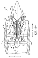
12 長手方向中心線、軸方向中心線
14 ファン区域
16 コアタービンエンジン
18 外側ケーシング
20 入口
22 ブースタ、低圧(LP)圧縮機
24 高圧(HP)圧縮機
26 燃焼区域
28 高圧(HP)タービン
30 低圧(LP)タービン
32 ジェット排気ノズル区域
34 軸、HPシャフト
36 軸
38 ファン
40 ファンブレード
42 ディスク
48 前ナセル
50 外側ナセル
52 出口案内羽根
54 下流区域
56 バイパス気流通路
58 空気
60 入口
62 空気58のうちの第1の部分
64 空気58のうちの第2の部分
66 燃焼ガス
68 HPタービン静翼
70 HPタービンロータブレード
72 LPタービン静翼
74 LPタービンロータブレード
76 ファンノズル排気区域
78 高温ガス路
80 燃焼器
82 第1のタービン段
82B ブレード部分
82N ノズル部分
84 第2のタービン段
84B ブレード部分
84N ノズル部分
86 燃焼室
88 前方端
90 燃料ノズル組立体
92 旋回翼
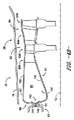
100 流路
101 流路組立体
102 単一の外壁、外壁
104 燃焼器部分
106 タービン部分
108 外側ライナ
110 外側バンド
112 シュラウド
114 外側バンド
116 シュラウド
118 燃焼器ドーム
120 内壁
122 内側ライナ
124 内側バンド
126、128 ノズル翼
130 ブレード翼
132 ブレードプラットフォーム
134 第1の段のロータ
136 内側バンド
138 第2の段のロータ
140 先端
142 開口
144 外壁のフランジ
146 内壁のフランジ
150 軸方向滑り継手
152 外側羽根
154 内側羽根
156 燃焼器ドーム本体
158 外側端
160 バネ要素
162 リップ
A 軸方向
R 径方向
Claims (14)
- ガスタービンエンジン(10)の流路(100)の外壁(102)であって、
前記ガスタービンエンジンの燃焼区域(26)を通じて延びる燃焼器部分(104)と、
前記ガスタービンエンジンのタービン区域(28)の少なくとも第1のタービン段(82)を通じて延びるタービン部分(106)と
を備え、
前記燃焼器部分と前記タービン部分とは、前記燃焼器部分と前記タービン部分とが1つだけの単一構造となるように一体に形成され、
前記単一構造は前記流路の外側境界を画定し、
前記燃焼器部分(104)は、前記燃焼区域(26)の燃焼器(80)の外側ライナ(108)を備え、
前記タービン部分(106)は、
前記第1のタービン段(82)のノズル部分(82N)の外側バンド(110)と、
前記第1のタービン段のブレード部分(82B)のシュラウド(112)と、
第2のタービン段(84)のノズル部分(84N)の外側バンド(114)と、
前記第2のタービン段のブレード部分(84B)のシュラウド(116)と
を備える、外壁。 - 前記燃焼器部分(104)は、前記燃焼器(80)の前方端(88)にわたって延びる燃焼器ドーム(118)と、前記燃焼器の内側ライナ(122)とをさらに備え、前記タービン部分(106)は、前記第1のタービン段のノズル部分(82N)の内側バンド(124)をさらに備える、請求項1に記載の外壁。
- 前記タービン部分(106)は、前記第1のタービン段のノズル部分(82N)内に複数のノズル翼(126)をさらに備える、請求項1に記載の外壁。
- 前記第1のタービン段(82)の前記外側バンド(110)および前記シュラウド(112)は前記ガスタービンエンジン(10)の軸方向中心線(12)に向かって収束し、前記第2のタービン段(84)の前記外側バンド(114)および前記シュラウド(116)は前記軸方向中心線から離れるように発散する、請求項1に記載の外壁。
- 前記燃焼器部分(104)と前記タービン部分(106)とは、前記単一構造がセラミックマトリックス複合材構成要素であるようにセラミックマトリックス複合材料から一体に形成される、請求項1に記載の外壁。
- ガスタービンエンジン(10)のための流路組立体(101)であって、
前記ガスタービンエンジンの燃焼区域(26)の燃焼器(80)の前方端(88)に位置決めされる燃焼器ドーム(118)と、
前記燃焼器ドームから前記ガスタービンエンジンのタービン区域(28)の少なくとも第1のタービン段(82)を通じて延びる外壁(102)であって、前記外壁(102)は、請求項1から5のいずれか一項に記載の外壁(102)である、外壁(102)と、
前記燃焼器ドームから少なくとも前記燃焼区域を通じて延びる内壁(120)と
を備え、
前記燃焼器ドームは前記外壁から前記内壁へと径方向に延び、
前記燃焼器ドーム、前記外壁、および前記内壁は、前記燃焼器ドーム、前記外壁、および前記内壁が1つだけの単一構造となるように、一体に形成される、流路組立体。 - 前記単一構造は概して環状の流路(100)を画定する、請求項6に記載の流路組立体。
- 前記燃焼器ドーム(118)は、燃料ノズル組立体(90)の受け入れのための開口(142)を画定する、請求項6に記載の流路組立体。
- 前記単一構造は、複数のあらかじめ含浸させられたセラミックマトリックス複合材テープから形成される、請求項6に記載の流路組立体。
- 前記単一構造は炭化ケイ素繊維の生地から形成される 請求項6に記載の流路組立体。
- 燃焼区域(104)と、
前記燃焼区域のすぐ下流に位置決めされる第1のタービン段(82)、および、前記第1のタービン段のすぐ下流に位置決めされる第2のタービン段(84)を含むタービン区域(106)と
を備えるタービンエンジン(10)であって、
前記燃焼区域および前記タービン区域は流路(100)を画定し、
前記燃焼区域は、前記燃焼区域を通る前記流路の外側境界を定める外側ライナ(108)を含み、
前記第1のタービン段および前記第2のタービン段の各々はノズル部分(82N、84N)とブレード部分(82B、84B)とを含み、各々のノズル部分は、前記ノズル部分を通る前記流路の外側境界を定める外側バンド(110、114)を備え、各々のブレード部分は、前記ブレード部分を通る前記流路の外側境界を定めるシュラウド(112、116)を備え、
前記外側ライナ(108)、前記外側バンド(110、114)、および前記シュラウド(112、116)は、前記外側ライナ、前記外側バンド、および前記シュラウドが1つだけの単一構造となるように、一体に形成される、ガスタービンエンジン。 - 一体にされた前記外側ライナ、前記外側バンド、および前記シュラウドによって形成される前記単一構造は前記流路の単一の外壁であり、前記単一の外壁は、前記燃焼区域、前記第1のタービン段、および前記第2のタービン段を通る前記流路の単一の外側境界を定める、請求項11に記載のガスタービンエンジン。
- 前記燃焼区域は、前記燃焼区域を通る前記流路の内側境界を定める内側ライナをさらに備え、前記内側ライナは、前記内側ライナが前記単一構造の一部分となるように、前記外側ライナ、前記外側バンド、および前記シュラウドと一体に形成される、請求項11に記載のガスタービンエンジン。
- 各々のノズル部分は、前記ノズル部分を通る前記流路の内側境界を定める内側バンドをさらに備え、前記第1のタービン段のノズル部分の前記内側バンドは、前記第1のタービン段のノズル部分の前記内側バンドが前記単一構造の一部分となるように、前記内側ライナ、前記外側ライナ、前記外側バンド、および前記シュラウドと一体に形成される、請求項13に記載のガスタービンエンジン。
Applications Claiming Priority (3)
| Application Number | Priority Date | Filing Date | Title |
|---|---|---|---|
| US15/417,399 | 2017-01-27 | ||
| US15/417,399 US10393381B2 (en) | 2017-01-27 | 2017-01-27 | Unitary flow path structure |
| PCT/US2017/064794 WO2018140135A1 (en) | 2017-01-27 | 2017-12-06 | Unitary flowpath structure |
Publications (2)
| Publication Number | Publication Date |
|---|---|
| JP2020507032A JP2020507032A (ja) | 2020-03-05 |
| JP6855100B2 true JP6855100B2 (ja) | 2021-04-07 |
Family
ID=62977731
Family Applications (1)
| Application Number | Title | Priority Date | Filing Date |
|---|---|---|---|
| JP2019540592A Active JP6855100B2 (ja) | 2017-01-27 | 2017-12-06 | 単一流路構造 |
Country Status (6)
| Country | Link |
|---|---|
| US (2) | US10393381B2 (ja) |
| EP (1) | EP3574189B1 (ja) |
| JP (1) | JP6855100B2 (ja) |
| CN (1) | CN110234845B (ja) |
| CA (1) | CA3049864C (ja) |
| WO (1) | WO2018140135A1 (ja) |
Families Citing this family (16)
| Publication number | Priority date | Publication date | Assignee | Title |
|---|---|---|---|---|
| US10816199B2 (en) * | 2017-01-27 | 2020-10-27 | General Electric Company | Combustor heat shield and attachment features |
| US10393381B2 (en) | 2017-01-27 | 2019-08-27 | General Electric Company | Unitary flow path structure |
| US10253643B2 (en) | 2017-02-07 | 2019-04-09 | General Electric Company | Airfoil fluid curtain to mitigate or prevent flow path leakage |
| US10253641B2 (en) | 2017-02-23 | 2019-04-09 | General Electric Company | Methods and assemblies for attaching airfoils within a flow path |
| US10247019B2 (en) | 2017-02-23 | 2019-04-02 | General Electric Company | Methods and features for positioning a flow path inner boundary within a flow path assembly |
| US10378373B2 (en) | 2017-02-23 | 2019-08-13 | General Electric Company | Flow path assembly with airfoils inserted through flow path boundary |
| US10385709B2 (en) | 2017-02-23 | 2019-08-20 | General Electric Company | Methods and features for positioning a flow path assembly within a gas turbine engine |
| US10385731B2 (en) | 2017-06-12 | 2019-08-20 | General Electric Company | CTE matching hanger support for CMC structures |
| US11248789B2 (en) | 2018-12-07 | 2022-02-15 | Raytheon Technologies Corporation | Gas turbine engine with integral combustion liner and turbine nozzle |
| US11073039B1 (en) | 2020-01-24 | 2021-07-27 | Rolls-Royce Plc | Ceramic matrix composite heat shield for use in a turbine vane and a turbine shroud ring |
| US11268394B2 (en) | 2020-03-13 | 2022-03-08 | General Electric Company | Nozzle assembly with alternating inserted vanes for a turbine engine |
| CN111692612A (zh) * | 2020-06-19 | 2020-09-22 | 宜兴市新立织造有限公司 | 一种三维机织航空火焰稳定器及其制备方法 |
| US11428160B2 (en) | 2020-12-31 | 2022-08-30 | General Electric Company | Gas turbine engine with interdigitated turbine and gear assembly |
| US11859819B2 (en) | 2021-10-15 | 2024-01-02 | General Electric Company | Ceramic composite combustor dome and liners |
| US11879362B1 (en) | 2023-02-21 | 2024-01-23 | Rolls-Royce Corporation | Segmented ceramic matrix composite vane endwall integration with turbine shroud ring and mounting thereof |
| US12110802B1 (en) | 2023-04-07 | 2024-10-08 | Rolls-Royce Corporation | Full hoop ceramic matrix composite vane endwall integration with turbine shroud ring and mounting thereof |
Family Cites Families (137)
| Publication number | Priority date | Publication date | Assignee | Title |
|---|---|---|---|---|
| US3527544A (en) | 1968-12-12 | 1970-09-08 | Gen Motors Corp | Cooled blade shroud |
| US3546880A (en) * | 1969-08-04 | 1970-12-15 | Avco Corp | Compressors for gas turbine engines |
| US3842595A (en) | 1972-12-26 | 1974-10-22 | Gen Electric | Modular gas turbine engine |
| FR2312654A1 (fr) | 1975-05-28 | 1976-12-24 | Snecma | Perfectionnements aux chambres de combustion pour moteurs a turbine a gaz |
| US4395195A (en) | 1980-05-16 | 1983-07-26 | United Technologies Corporation | Shroud ring for use in a gas turbine engine |
| US4458479A (en) | 1981-10-13 | 1984-07-10 | General Motors Corporation | Diffuser for gas turbine engine |
| US4424667A (en) | 1982-06-07 | 1984-01-10 | Fanning Arthur E | Apparatus for increasing the efficiency of a gas turbine engine |
| US4686823A (en) | 1986-04-28 | 1987-08-18 | United Technologies Corporation | Sliding joint for an annular combustor |
| US5015540A (en) | 1987-06-01 | 1991-05-14 | General Electric Company | Fiber-containing composite |
| US5330854A (en) | 1987-09-24 | 1994-07-19 | General Electric Company | Filament-containing composite |
| US5336350A (en) | 1989-10-31 | 1994-08-09 | General Electric Company | Process for making composite containing fibrous material |
| US4990056A (en) | 1989-11-16 | 1991-02-05 | General Motors Corporation | Stator vane stage in axial flow compressor |
| US5117637A (en) | 1990-08-02 | 1992-06-02 | General Electric Company | Combustor dome assembly |
| GB9021201D0 (en) | 1990-09-28 | 1990-11-14 | Ruston Gas Turbines Ltd | Gas turbine combustors |
| US5207064A (en) | 1990-11-21 | 1993-05-04 | General Electric Company | Staged, mixed combustor assembly having low emissions |
| US5142859A (en) * | 1991-02-22 | 1992-09-01 | Solar Turbines, Incorporated | Turbine cooling system |
| US5392614A (en) | 1992-03-23 | 1995-02-28 | General Electric Company | Gas turbine engine cooling system |
| US5406787A (en) | 1993-08-20 | 1995-04-18 | Lockheed Corporation Lockeed Fort Worth Company | After-burning turbo-jet engine with a fixed geometry exhaust nozzle |
| US5465571A (en) | 1993-12-21 | 1995-11-14 | United Technologies Corporation | Fuel nozzle attachment in gas turbine combustors |
| US5628938A (en) | 1994-11-18 | 1997-05-13 | General Electric Company | Method of making a ceramic composite by infiltration of a ceramic preform |
| DE19515537A1 (de) | 1995-04-27 | 1996-10-31 | Bmw Rolls Royce Gmbh | Kopfteil einer Gasturbinen-Ringbrennkammer |
| US5562408A (en) * | 1995-06-06 | 1996-10-08 | General Electric Company | Isolated turbine shroud |
| US5630700A (en) | 1996-04-26 | 1997-05-20 | General Electric Company | Floating vane turbine nozzle |
| US6024898A (en) | 1996-12-30 | 2000-02-15 | General Electric Company | Article and method for making complex shaped preform and silicon carbide composite by melt infiltration |
| US7519549B1 (en) | 1997-06-19 | 2009-04-14 | Presentation Specialist Technologies, Llc | Inventory sales system and method |
| US5842595A (en) | 1997-10-20 | 1998-12-01 | Williams; Dale L. | Mobile trash/garbage bag holder with open bottom |
| US6212870B1 (en) | 1998-09-22 | 2001-04-10 | General Electric Company | Self fixturing combustor dome assembly |
| US6403158B1 (en) | 1999-03-05 | 2002-06-11 | General Electric Company | Porous body infiltrating method |
| US6761534B1 (en) | 1999-04-05 | 2004-07-13 | General Electric Company | Cooling circuit for a gas turbine bucket and tip shroud |
| US6269628B1 (en) * | 1999-06-10 | 2001-08-07 | Pratt & Whitney Canada Corp. | Apparatus for reducing combustor exit duct cooling |
| US6207064B1 (en) | 1999-07-12 | 2001-03-27 | Joseph Gargas | Ozone contact chamber |
| US6200092B1 (en) | 1999-09-24 | 2001-03-13 | General Electric Company | Ceramic turbine nozzle |
| US6314739B1 (en) | 2000-01-13 | 2001-11-13 | General Electric Company | Brazeless combustor dome assembly |
| DE10019440A1 (de) | 2000-04-19 | 2001-10-25 | Rolls Royce Deutschland | Zwischenstufendichtungsträger |
| US6530744B2 (en) * | 2001-05-29 | 2003-03-11 | General Electric Company | Integral nozzle and shroud |
| US6503441B2 (en) | 2001-05-30 | 2003-01-07 | General Electric Company | Method for producing melt-infiltrated ceramic composites using formed supports |
| FR2825779B1 (fr) * | 2001-06-06 | 2003-08-29 | Snecma Moteurs | Chambre de combustion munie d'un systeme de fixation de fond de chambre |
| FR2825784B1 (fr) * | 2001-06-06 | 2003-08-29 | Snecma Moteurs | Accrochage de chambre de combustion cmc de turbomachine utilisant les trous de dilution |
| FR2825787B1 (fr) | 2001-06-06 | 2004-08-27 | Snecma Moteurs | Montage de chambre de combustion cmc de turbomachine par viroles de liaison souples |
| US6543996B2 (en) | 2001-06-28 | 2003-04-08 | General Electric Company | Hybrid turbine nozzle |
| US6581386B2 (en) | 2001-09-29 | 2003-06-24 | General Electric Company | Threaded combustor baffle |
| US6619030B1 (en) | 2002-03-01 | 2003-09-16 | General Electric Company | Aircraft engine with inter-turbine engine frame supported counter rotating low pressure turbine rotors |
| GB2388161A (en) | 2002-05-02 | 2003-11-05 | Rolls Royce Plc | Gas turbine engine compressor casing |
| US20040067316A1 (en) | 2002-10-04 | 2004-04-08 | Paul Gray | Method for processing silicon-carbide materials using organic film formers |
| US6851263B2 (en) * | 2002-10-29 | 2005-02-08 | General Electric Company | Liner for a gas turbine engine combustor having trapped vortex cavity |
| US6904757B2 (en) | 2002-12-20 | 2005-06-14 | General Electric Company | Mounting assembly for the forward end of a ceramic matrix composite liner in a gas turbine engine combustor |
| US6893214B2 (en) | 2002-12-20 | 2005-05-17 | General Electric Company | Shroud segment and assembly with surface recessed seal bridging adjacent members |
| US7093440B2 (en) | 2003-06-11 | 2006-08-22 | General Electric Company | Floating liner combustor |
| US7186078B2 (en) | 2003-07-04 | 2007-03-06 | Ishikawajima-Harima Heavy Industries Co., Ltd. | Turbine shroud segment |
| US7370467B2 (en) | 2003-07-29 | 2008-05-13 | Pratt & Whitney Canada Corp. | Turbofan case and method of making |
| US7062920B2 (en) | 2003-08-11 | 2006-06-20 | General Electric Company | Combustor dome assembly of a gas turbine engine having a free floating swirler |
| GB2412702B (en) | 2004-03-31 | 2006-05-03 | Rolls Royce Plc | Seal assembly |
| FR2871846B1 (fr) | 2004-06-17 | 2006-09-29 | Snecma Moteurs Sa | Chambre de combustion en cmc de turbine a gaz supportee dans un carter metallique par des organes de liaison en cmc |
| FR2871845B1 (fr) | 2004-06-17 | 2009-06-26 | Snecma Moteurs Sa | Montage de chambre de combustion de turbine a gaz avec distributeur integre de turbine haute pression |
| FR2871847B1 (fr) * | 2004-06-17 | 2006-09-29 | Snecma Moteurs Sa | Montage d'un distributeur de turbine sur une chambre de combustion a parois en cmc dans une turbine a gaz |
| FR2871844B1 (fr) * | 2004-06-17 | 2006-09-29 | Snecma Moteurs Sa | Montage etanche d'un distributeur de turbine haute pression sur une extremite d'une chambre de combustion dans une turbine a gaz |
| WO2006059971A2 (en) | 2004-12-01 | 2006-06-08 | United Technologies Corporation | Tip turbine engine integral fan, combustor, and turbine case |
| US7527469B2 (en) * | 2004-12-10 | 2009-05-05 | Siemens Energy, Inc. | Transition-to-turbine seal apparatus and kit for transition/turbine junction of a gas turbine engine |
| US7452182B2 (en) | 2005-04-07 | 2008-11-18 | Siemens Energy, Inc. | Multi-piece turbine vane assembly |
| US7329087B2 (en) | 2005-09-19 | 2008-02-12 | General Electric Company | Seal-less CMC vane to platform interfaces |
| US7546743B2 (en) | 2005-10-12 | 2009-06-16 | General Electric Company | Bolting configuration for joining ceramic combustor liner to metal mounting attachments |
| US7665307B2 (en) * | 2005-12-22 | 2010-02-23 | United Technologies Corporation | Dual wall combustor liner |
| US7934382B2 (en) | 2005-12-22 | 2011-05-03 | United Technologies Corporation | Combustor turbine interface |
| GB2455021B (en) | 2006-09-14 | 2011-03-23 | Solar Turbines Inc | Splash plate dome assembly for a turbine engine |
| US8668437B1 (en) * | 2006-09-22 | 2014-03-11 | Siemens Energy, Inc. | Turbine engine cooling fluid feed system |
| US7950234B2 (en) | 2006-10-13 | 2011-05-31 | Siemens Energy, Inc. | Ceramic matrix composite turbine engine components with unitary stiffening frame |
| US8171736B2 (en) * | 2007-01-30 | 2012-05-08 | Pratt & Whitney Canada Corp. | Combustor with chamfered dome |
| FR2913717A1 (fr) * | 2007-03-15 | 2008-09-19 | Snecma Propulsion Solide Sa | Ensemble d'anneau de turbine pour turbine a gaz |
| US8240980B1 (en) | 2007-10-19 | 2012-08-14 | Florida Turbine Technologies, Inc. | Turbine inter-stage gap cooling and sealing arrangement |
| US8162605B2 (en) * | 2008-01-14 | 2012-04-24 | United Technologies Corporation | Gas turbine engine case |
| FR2928994B1 (fr) | 2008-03-19 | 2010-04-02 | Snecma | Chambre de combustion de turbomachine. |
| FR2929689B1 (fr) | 2008-04-03 | 2013-04-12 | Snecma Propulsion Solide | Chambre de combustion de turbine a gaz a parois interne et externe sectorisees |
| FR2929690B1 (fr) | 2008-04-03 | 2012-08-17 | Snecma Propulsion Solide | Chambre de combustion sectorisee en cmc pour turbine a gaz |
| US9822649B2 (en) * | 2008-11-12 | 2017-11-21 | General Electric Company | Integrated combustor and stage 1 nozzle in a gas turbine and method |
| DE102008060847B4 (de) * | 2008-12-06 | 2020-03-19 | MTU Aero Engines AG | Strömungsmaschine |
| US8327648B2 (en) * | 2008-12-09 | 2012-12-11 | Pratt & Whitney Canada Corp. | Combustor liner with integrated anti-rotation and removal feature |
| US8745989B2 (en) | 2009-04-09 | 2014-06-10 | Pratt & Whitney Canada Corp. | Reverse flow ceramic matrix composite combustor |
| US8246305B2 (en) | 2009-10-01 | 2012-08-21 | Pratt & Whitney Canada Corp. | Gas turbine engine balancing |
| US8776525B2 (en) | 2009-12-29 | 2014-07-15 | Rolls-Royce North American Technologies, Inc. | Gas turbine engine and combustor |
| US8448023B2 (en) | 2010-04-30 | 2013-05-21 | Honeywell International Inc. | Approach for data integrity in an embedded device environment |
| US8943835B2 (en) | 2010-05-10 | 2015-02-03 | General Electric Company | Gas turbine engine combustor with CMC heat shield and methods therefor |
| US8753073B2 (en) | 2010-06-23 | 2014-06-17 | General Electric Company | Turbine shroud sealing apparatus |
| US9010123B2 (en) | 2010-07-26 | 2015-04-21 | Honeywell International Inc. | Combustors with quench inserts |
| US20120031099A1 (en) * | 2010-08-04 | 2012-02-09 | Mahesh Bathina | Combustor assembly for use in a turbine engine and methods of assembling same |
| EP2431571B1 (fr) | 2010-09-16 | 2013-06-05 | Techspace Aero S.A. | Assemblage d'un aube et d'un support composite par scellage |
| EP2466074A1 (de) | 2010-12-15 | 2012-06-20 | MTU Aero Engines GmbH | Gasturbinentriebwerk mit Kolbenringdichtung |
| US8905711B2 (en) | 2011-05-26 | 2014-12-09 | United Technologies Corporation | Ceramic matrix composite vane structures for a gas turbine engine turbine |
| US9039364B2 (en) | 2011-06-29 | 2015-05-26 | United Technologies Corporation | Integrated case and stator |
| US9335051B2 (en) | 2011-07-13 | 2016-05-10 | United Technologies Corporation | Ceramic matrix composite combustor vane ring assembly |
| FR2983428B1 (fr) | 2011-12-01 | 2014-01-17 | Snecma Propulsion Solide | Procede de fabrication d'une aube de turbomachine en materiau composite a plates-formes integrees |
| US20130157037A1 (en) | 2011-12-14 | 2013-06-20 | General Electric Company | Slurry composition, prepreg tape, and process for producing composites |
| US9284231B2 (en) | 2011-12-16 | 2016-03-15 | General Electric Company | Hydrocarbon film protected refractory carbide components and use |
| US9255487B2 (en) | 2012-01-31 | 2016-02-09 | United Technologies Corporation | Gas turbine engine seal carrier |
| US8887487B2 (en) | 2012-01-31 | 2014-11-18 | United Technologies Corporation | Geared turbofan gas turbine engine architecture |
| US8839627B2 (en) * | 2012-01-31 | 2014-09-23 | United Technologies Corporation | Annular combustor |
| US9308708B2 (en) | 2012-03-23 | 2016-04-12 | General Electric Company | Process for producing ceramic composite components |
| FR2989426B1 (fr) * | 2012-04-11 | 2014-03-28 | Snecma | Turbomachine, telle qu'un turboreacteur ou un turbopropulseur d'avion |
| US9169736B2 (en) | 2012-07-16 | 2015-10-27 | United Technologies Corporation | Joint between airfoil and shroud |
| WO2014051700A1 (en) | 2012-09-28 | 2014-04-03 | United Technologies Corporation | Radially coacting ring seal |
| US20140190171A1 (en) | 2013-01-10 | 2014-07-10 | Honeywell International Inc. | Combustors with hybrid walled liners |
| EP2964887B1 (en) | 2013-03-08 | 2019-06-26 | Rolls-Royce North American Technologies, Inc. | Method for forming a gas turbine engine composite airfoil assembly and corresponding airfoil assembly |
| EP2971577B1 (en) | 2013-03-13 | 2018-08-29 | Rolls-Royce Corporation | Turbine shroud |
| US9328620B2 (en) * | 2013-03-13 | 2016-05-03 | Rolls-Royce Corporation | Method for making gas turbine engine composite structure |
| EP2971735A1 (en) | 2013-03-15 | 2016-01-20 | Rolls-Royce Corporation | Ultra high bypass ratio turbofan engine |
| US10100670B2 (en) | 2013-06-14 | 2018-10-16 | United Technologies Corporation | Heatshield assembly with double lap joint for a gas turbine engine |
| US10125620B2 (en) | 2013-07-29 | 2018-11-13 | United Technologies Corporation | Gas turbine engine CMC airfoil assembly |
| US10202869B2 (en) | 2013-08-22 | 2019-02-12 | United Technologies Corporation | Connection for a fairing in a mid-turbine frame of a gas turbine engine |
| WO2015088619A2 (en) | 2013-10-16 | 2015-06-18 | United Technologies Corporation | Geared turbofan engine with targeted modular efficiency |
| US10502163B2 (en) | 2013-11-01 | 2019-12-10 | United Technologies Corporation | Geared turbofan arrangement with core split power ratio |
| DE102014204466A1 (de) | 2014-03-11 | 2015-10-01 | Rolls-Royce Deutschland Ltd & Co Kg | Brennkammer einer Gasturbine |
| GB201406386D0 (en) | 2014-04-09 | 2014-05-21 | Rolls Royce Plc | Gas turbine engine |
| EP3140516B1 (en) | 2014-05-08 | 2018-09-26 | Siemens Aktiengesellschaft | Turbine assembly and corresponding method of operation |
| FR3020865B1 (fr) | 2014-05-12 | 2016-05-20 | Snecma | Chambre annulaire de combustion |
| US10202185B2 (en) | 2014-06-10 | 2019-02-12 | United Technologies Corporation | Geared turbofan with improved spinner |
| US10012104B2 (en) | 2014-10-14 | 2018-07-03 | United Technologies Corporation | Gas turbine engine convergent/divergent nozzle with unitary synchronization ring for roller track nozzle |
| EP3048254B1 (en) | 2015-01-22 | 2017-12-27 | Rolls-Royce Corporation | Vane assembly for a gas turbine engine |
| CN204593455U (zh) * | 2015-01-23 | 2015-08-26 | 北京华清燃气轮机与煤气化联合循环工程技术有限公司 | 热通道部件一体燃烧室 |
| CN104595926A (zh) * | 2015-01-23 | 2015-05-06 | 北京华清燃气轮机与煤气化联合循环工程技术有限公司 | 热通道部件一体燃烧室 |
| US9920641B2 (en) | 2015-02-23 | 2018-03-20 | United Technologies Corporation | Gas turbine engine mid-turbine frame configuration |
| US10578021B2 (en) | 2015-06-26 | 2020-03-03 | Delavan Inc | Combustion systems |
| DE102015212573A1 (de) | 2015-07-06 | 2017-01-12 | Rolls-Royce Deutschland Ltd & Co Kg | Gasturbinenbrennkammer mit integriertem Turbinenvorleitrad sowie Verfahren zu deren Herstellung |
| US11149646B2 (en) | 2015-09-02 | 2021-10-19 | General Electric Company | Piston ring assembly for a turbine engine |
| US10317085B2 (en) | 2016-02-25 | 2019-06-11 | General Electric Company | Combustor assembly |
| JP2017170807A (ja) | 2016-03-24 | 2017-09-28 | カシオ計算機株式会社 | 印刷補助装置、印刷装置、印刷システム、報知方法及びプログラム |
| US20170370583A1 (en) | 2016-06-22 | 2017-12-28 | General Electric Company | Ceramic Matrix Composite Component for a Gas Turbine Engine |
| US10450897B2 (en) | 2016-07-18 | 2019-10-22 | General Electric Company | Shroud for a gas turbine engine |
| US20180216575A1 (en) | 2017-01-27 | 2018-08-02 | General Electric Company | Cool core gas turbine engine |
| US10393381B2 (en) | 2017-01-27 | 2019-08-27 | General Electric Company | Unitary flow path structure |
| US10378770B2 (en) | 2017-01-27 | 2019-08-13 | General Electric Company | Unitary flow path structure |
| US10371383B2 (en) | 2017-01-27 | 2019-08-06 | General Electric Company | Unitary flow path structure |
| US11111858B2 (en) | 2017-01-27 | 2021-09-07 | General Electric Company | Cool core gas turbine engine |
| US10253641B2 (en) | 2017-02-23 | 2019-04-09 | General Electric Company | Methods and assemblies for attaching airfoils within a flow path |
| US10378373B2 (en) | 2017-02-23 | 2019-08-13 | General Electric Company | Flow path assembly with airfoils inserted through flow path boundary |
| US10247019B2 (en) | 2017-02-23 | 2019-04-02 | General Electric Company | Methods and features for positioning a flow path inner boundary within a flow path assembly |
| US10385709B2 (en) | 2017-02-23 | 2019-08-20 | General Electric Company | Methods and features for positioning a flow path assembly within a gas turbine engine |
| US10385776B2 (en) | 2017-02-23 | 2019-08-20 | General Electric Company | Methods for assembling a unitary flow path structure |
| US10520197B2 (en) * | 2017-06-01 | 2019-12-31 | General Electric Company | Single cavity trapped vortex combustor with CMC inner and outer liners |
-
2017
- 2017-01-27 US US15/417,399 patent/US10393381B2/en active Active
- 2017-12-06 JP JP2019540592A patent/JP6855100B2/ja active Active
- 2017-12-06 WO PCT/US2017/064794 patent/WO2018140135A1/en not_active Ceased
- 2017-12-06 CN CN201780084774.9A patent/CN110234845B/zh active Active
- 2017-12-06 CA CA3049864A patent/CA3049864C/en active Active
- 2017-12-06 EP EP17894433.6A patent/EP3574189B1/en active Active
-
2019
- 2019-04-30 US US16/398,439 patent/US11143402B2/en active Active
Also Published As
| Publication number | Publication date |
|---|---|
| JP2020507032A (ja) | 2020-03-05 |
| EP3574189A4 (en) | 2020-11-25 |
| US11143402B2 (en) | 2021-10-12 |
| WO2018140135A1 (en) | 2018-08-02 |
| CA3049864C (en) | 2022-06-14 |
| US20200025377A1 (en) | 2020-01-23 |
| CN110234845A (zh) | 2019-09-13 |
| CA3049864A1 (en) | 2018-08-02 |
| US10393381B2 (en) | 2019-08-27 |
| US20180216822A1 (en) | 2018-08-02 |
| CN110234845B (zh) | 2022-01-11 |
| EP3574189A1 (en) | 2019-12-04 |
| EP3574189B1 (en) | 2023-05-24 |
Similar Documents
| Publication | Publication Date | Title |
|---|---|---|
| JP6855099B2 (ja) | 単一流路構造 | |
| US11828199B2 (en) | Methods and assemblies for attaching airfoils within a flow path | |
| JP6861833B2 (ja) | 単一流路構造 | |
| US11143402B2 (en) | Unitary flow path structure | |
| US10385709B2 (en) | Methods and features for positioning a flow path assembly within a gas turbine engine | |
| US10378373B2 (en) | Flow path assembly with airfoils inserted through flow path boundary | |
| US10385776B2 (en) | Methods for assembling a unitary flow path structure | |
| US11149575B2 (en) | Airfoil fluid curtain to mitigate or prevent flow path leakage | |
| US11384651B2 (en) | Methods and features for positioning a flow path inner boundary within a flow path assembly |
Legal Events
| Date | Code | Title | Description |
|---|---|---|---|
| A521 | Request for written amendment filed |
Free format text: JAPANESE INTERMEDIATE CODE: A523 Effective date: 20190926 |
|
| A621 | Written request for application examination |
Free format text: JAPANESE INTERMEDIATE CODE: A621 Effective date: 20190926 |
|
| A977 | Report on retrieval |
Free format text: JAPANESE INTERMEDIATE CODE: A971007 Effective date: 20200813 |
|
| A131 | Notification of reasons for refusal |
Free format text: JAPANESE INTERMEDIATE CODE: A131 Effective date: 20200824 |
|
| A521 | Request for written amendment filed |
Free format text: JAPANESE INTERMEDIATE CODE: A523 Effective date: 20201124 |
|
| TRDD | Decision of grant or rejection written | ||
| A01 | Written decision to grant a patent or to grant a registration (utility model) |
Free format text: JAPANESE INTERMEDIATE CODE: A01 Effective date: 20210215 |
|
| A61 | First payment of annual fees (during grant procedure) |
Free format text: JAPANESE INTERMEDIATE CODE: A61 Effective date: 20210311 |
|
| R150 | Certificate of patent or registration of utility model |
Ref document number: 6855100 Country of ref document: JP Free format text: JAPANESE INTERMEDIATE CODE: R150 |
|
| R250 | Receipt of annual fees |
Free format text: JAPANESE INTERMEDIATE CODE: R250 |
|
| R250 | Receipt of annual fees |
Free format text: JAPANESE INTERMEDIATE CODE: R250 |