JP6862014B2 - Power transmission system and manufacturing method of power transmission system - Google Patents
Power transmission system and manufacturing method of power transmission system Download PDFInfo
- Publication number
- JP6862014B2 JP6862014B2 JP2019539580A JP2019539580A JP6862014B2 JP 6862014 B2 JP6862014 B2 JP 6862014B2 JP 2019539580 A JP2019539580 A JP 2019539580A JP 2019539580 A JP2019539580 A JP 2019539580A JP 6862014 B2 JP6862014 B2 JP 6862014B2
- Authority
- JP
- Japan
- Prior art keywords
- electrode
- stator
- rotor
- magnet
- power transmission
- Prior art date
- Legal status (The legal status is an assumption and is not a legal conclusion. Google has not performed a legal analysis and makes no representation as to the accuracy of the status listed.)
- Active
Links
Images









Classifications
-
- H—ELECTRICITY
- H02—GENERATION; CONVERSION OR DISTRIBUTION OF ELECTRIC POWER
- H02J—ELECTRIC POWER NETWORKS; CIRCUIT ARRANGEMENTS OR SYSTEMS FOR SUPPLYING OR DISTRIBUTING ELECTRIC POWER; SYSTEMS FOR STORING ELECTRIC ENERGY
- H02J50/00—Circuit arrangements or systems for wireless supply or distribution of electric power
- H02J50/05—Circuit arrangements or systems for wireless supply or distribution of electric power using capacitive coupling
-
- H—ELECTRICITY
- H01—ELECTRIC ELEMENTS
- H01F—MAGNETS; INDUCTANCES; TRANSFORMERS; SELECTION OF MATERIALS FOR THEIR MAGNETIC PROPERTIES
- H01F7/00—Magnets
- H01F7/02—Permanent magnets [PM]
- H01F7/0231—Magnetic circuits with PM for power or force generation
- H01F7/0247—Orientating, locating, transporting arrangements
-
- H—ELECTRICITY
- H02—GENERATION; CONVERSION OR DISTRIBUTION OF ELECTRIC POWER
- H02J—ELECTRIC POWER NETWORKS; CIRCUIT ARRANGEMENTS OR SYSTEMS FOR SUPPLYING OR DISTRIBUTING ELECTRIC POWER; SYSTEMS FOR STORING ELECTRIC ENERGY
- H02J50/00—Circuit arrangements or systems for wireless supply or distribution of electric power
- H02J50/40—Circuit arrangements or systems for wireless supply or distribution of electric power using two or more transmitting or receiving devices
-
- H—ELECTRICITY
- H02—GENERATION; CONVERSION OR DISTRIBUTION OF ELECTRIC POWER
- H02K—DYNAMO-ELECTRIC MACHINES
- H02K1/00—Details of the magnetic circuit
- H02K1/06—Details of the magnetic circuit characterised by the shape, form or construction
- H02K1/22—Rotating parts of the magnetic circuit
- H02K1/27—Rotor cores with permanent magnets
- H02K1/2793—Rotors axially facing stators
- H02K1/2795—Rotors axially facing stators the rotor consisting of two or more circumferentially positioned magnets
- H02K1/2796—Rotors axially facing stators the rotor consisting of two or more circumferentially positioned magnets where both axial sides of the rotor face a stator
-
- H—ELECTRICITY
- H02—GENERATION; CONVERSION OR DISTRIBUTION OF ELECTRIC POWER
- H02K—DYNAMO-ELECTRIC MACHINES
- H02K1/00—Details of the magnetic circuit
- H02K1/06—Details of the magnetic circuit characterised by the shape, form or construction
- H02K1/22—Rotating parts of the magnetic circuit
- H02K1/27—Rotor cores with permanent magnets
- H02K1/2793—Rotors axially facing stators
- H02K1/2795—Rotors axially facing stators the rotor consisting of two or more circumferentially positioned magnets
- H02K1/2798—Rotors axially facing stators the rotor consisting of two or more circumferentially positioned magnets where both axial sides of the stator face a rotor
-
- H—ELECTRICITY
- H02—GENERATION; CONVERSION OR DISTRIBUTION OF ELECTRIC POWER
- H02K—DYNAMO-ELECTRIC MACHINES
- H02K16/00—Machines with more than one rotor or stator
- H02K16/02—Machines with one stator and two or more rotors
- H02K16/025—Machines with one stator and two or more rotors with rotors and moving stators connected in a cascade
-
- H—ELECTRICITY
- H02—GENERATION; CONVERSION OR DISTRIBUTION OF ELECTRIC POWER
- H02K—DYNAMO-ELECTRIC MACHINES
- H02K5/00—Casings; Enclosures; Supports
- H02K5/04—Casings or enclosures characterised by the shape, form or construction thereof
- H02K5/14—Means for supporting or protecting brushes or brush holders
- H02K5/141—Means for supporting or protecting brushes or brush holders for cooperation with slip-rings
-
- H—ELECTRICITY
- H02—GENERATION; CONVERSION OR DISTRIBUTION OF ELECTRIC POWER
- H02K—DYNAMO-ELECTRIC MACHINES
- H02K15/00—Processes or apparatus specially adapted for manufacturing, assembling, maintaining or repairing of dynamo-electric machines
- H02K15/02—Processes or apparatus specially adapted for manufacturing, assembling, maintaining or repairing of dynamo-electric machines of stator or rotor bodies
- H02K15/03—Processes or apparatus specially adapted for manufacturing, assembling, maintaining or repairing of dynamo-electric machines of stator or rotor bodies having permanent magnets
-
- H—ELECTRICITY
- H02—GENERATION; CONVERSION OR DISTRIBUTION OF ELECTRIC POWER
- H02K—DYNAMO-ELECTRIC MACHINES
- H02K2213/00—Specific aspects, not otherwise provided for and not covered by codes H02K2201/00 - H02K2211/00
- H02K2213/03—Machines characterised by numerical values, ranges, mathematical expressions or similar information
-
- H—ELECTRICITY
- H02—GENERATION; CONVERSION OR DISTRIBUTION OF ELECTRIC POWER
- H02K—DYNAMO-ELECTRIC MACHINES
- H02K9/00—Arrangements for cooling or ventilating
- H02K9/19—Arrangements for cooling or ventilating for machines with closed casing and closed-circuit cooling using a liquid cooling medium, e.g. oil
-
- H—ELECTRICITY
- H02—GENERATION; CONVERSION OR DISTRIBUTION OF ELECTRIC POWER
- H02K—DYNAMO-ELECTRIC MACHINES
- H02K9/00—Arrangements for cooling or ventilating
- H02K9/22—Arrangements for cooling or ventilating by solid heat conducting material embedded in, or arranged in contact with, the stator or rotor, e.g. heat bridges
- H02K9/227—Heat sinks
Landscapes
- Engineering & Computer Science (AREA)
- Power Engineering (AREA)
- Computer Networks & Wireless Communication (AREA)
- Physics & Mathematics (AREA)
- Electromagnetism (AREA)
- Manufacturing & Machinery (AREA)
- Permanent Magnet Type Synchronous Machine (AREA)
- Micromachines (AREA)
- Permanent Field Magnets Of Synchronous Machinery (AREA)
Description
本発明は、電力伝送システム及び電力伝送システムの製造方法に関する。 The present invention relates to a power transmission system and a method for manufacturing a power transmission system.
従来より、電界結合によって電力を伝送する際の接合容量を増大させる技術は公開されている(特許文献1乃至2参照)。
Conventionally, a technique for increasing the junction capacitance when transmitting electric power by electric field coupling has been published (see
しかしながら、機械要素として、回転系へ送電するニーズが存在しており、従来の技術に対し、高速で回転する電極によって接合容量を増大させたいとする要望がある。
現在使用されているものは、スリップリングであり、接触により送電する手法が用いられている。接触式は、外部回路が不要であるため、容易に製作することができる。しかしながら、接触により送電するため、接点が摩耗したり、高速回転に伴い空気層が形成されて送電不能になったり、水分の混入に伴い水の膜が形成されて送電が遮られる等の問題が生じていた。特に、メンテナンスが必要となる点が問題となっていた。However, as a mechanical element, there is a need for power transmission to a rotating system, and there is a demand for increasing the junction capacitance by an electrode that rotates at high speed, as opposed to the conventional technology.
What is currently used is a slip ring, and a method of transmitting power by contact is used. Since the contact type does not require an external circuit, it can be easily manufactured. However, since power transmission is performed by contact, there are problems such as wear of the contacts, formation of an air layer due to high-speed rotation, which makes power transmission impossible, and formation of a water film due to the mixing of water, which interrupts power transmission. It was happening. In particular, there has been a problem that maintenance is required.
このような問題を解決する手法として、非接触による送電を可能とする電界結合方式がある。この電界結合方式の非接触電力伝送技術の分野では、従来より断片的なアイデアは提案されていたが、実用化には至らなかった。
実用化に至らなかったのは、2つの大きな課題があったためである。その1つは、高周波動作をさせなければならないという課題であり、残りの1つは、電極間がショートしないように回転電極の接合容量を安定的に得るという課題である。ただし、高周波動作をさせなければならないという課題は、GaN(窒化ガリウム)、SiC(炭化ケイ素)等の半導体が開発されたことにより解決された。これにより、残る課題は、電極間がショートしないように回転電極の接合容量を安定的に得るという課題である。As a method for solving such a problem, there is an electric field coupling method that enables non-contact power transmission. In the field of this electric field coupling type non-contact power transmission technology, fragmentary ideas have been proposed in the past, but they have not been put into practical use.
It was not put into practical use because there were two major problems. One of them is the problem that high frequency operation must be performed, and the other is the problem of stably obtaining the junction capacitance of the rotating electrodes so that the electrodes do not short-circuit. However, the problem of having to operate at high frequencies has been solved by the development of semiconductors such as GaN (gallium nitride) and SiC (silicon carbide). As a result, the remaining problem is to stably obtain the bonding capacitance of the rotating electrodes so that the electrodes are not short-circuited.
本発明は、このような状況に鑑みてなされたものであり、電極間がショートしないように回転電極の接合容量を安定的に得ることで接合容量を増大させる手法を提供することを目的とする。 The present invention has been made in view of such a situation, and an object of the present invention is to provide a method for increasing the bonding capacitance by stably obtaining the bonding capacitance of rotating electrodes so that the electrodes are not short-circuited. ..
上記目的を達成するため、本発明の一態様の電力伝送システムは、
1つ以上のロータ電極と1つ以上のロータスペーサとが交互に積層されたロータ電極ユニットと、1つ以上のステータ電極と1つ以上のステータスペーサとが交互に積層されたステータ電極ユニットと、からなる回転電極ユニットを備え、
前記回転電極ユニットは、
前記ロータ電極が送電電極である場合には、前記ステータ電極が受電電極であり、
前記ロータ電極が受電電極である場合には、前記ステータ電極が送電電極であり、
前記ロータ電極ユニットと前記ステータ電極ユニットとが入れ子状に組み合わせて相互に回転可能であり、
前記ロータ電極のうち少なくとも外周部は、磁性体からなる部材で構成され、
前記ステータスペーサは、前記ロータ電極の外周部を磁力で吸引する磁石を有する。In order to achieve the above object, the power transmission system of one aspect of the present invention is
A rotor electrode unit in which one or more rotor electrodes and one or more rotor spacers are alternately laminated, a stator electrode unit in which one or more stator electrodes and one or more stator spacers are alternately laminated, and a stator electrode unit. Equipped with a rotating electrode unit consisting of
The rotating electrode unit is
When the rotor electrode is a power transmission electrode, the stator electrode is a power receiving electrode.
When the rotor electrode is a power receiving electrode, the stator electrode is a power transmission electrode.
The rotor electrode unit and the stator electrode unit can be combined in a nested manner and rotate with each other.
At least the outer peripheral portion of the rotor electrode is made of a member made of a magnetic material.
The stator spacer has a magnet that magnetically attracts the outer peripheral portion of the rotor electrode.
また、前記ロータスペーサは、前記ステータ電極の外周部を磁力で吸引する磁石を有することができる。 Further, the rotor spacer may have a magnet that magnetically attracts the outer peripheral portion of the stator electrode.
また、前記ロータ電極と前記ステータ電極との間に形成された隙間に流体が存在し、
前記流体は封止されるようにすることができる。Further, a fluid exists in the gap formed between the rotor electrode and the stator electrode.
The fluid can be sealed.
また、本発明の一態様の電力伝送システムの製造方法は、
1つ以上のロータ電極と1つ以上のロータスペーサとが交互に積層されたロータ電極ユニットと、1つ以上のステータ電極と1つ以上のステータスペーサとが交互に積層されたステータ電極ユニットと、からなる回転電極ユニットを備え、前記回転電極ユニットは、前記ロータ電極が送電電極である場合には、前記ステータ電極が受電電極であり、前記ロータ電極が受電電極である場合には、前記ステータ電極が送電電極であり、前記ロータ電極ユニットと前記ステータ電極ユニットとが入れ子状に組み合わせて相互に回転可能であり、前記ロータ電極のうち少なくとも外周部は、磁性体からなる部材で構成される、電界結合電力伝送技術を適用した電力伝送システムの製造方法であって、
前記ステータスペーサに磁石を配置して、前記ロータ電極の外周部を磁力で吸引する工程と、
前記ロータ電極と前記ステータ電極との間に形成された隙間に流体を封止する工程と、
前記ステータスペーサに配置された前記磁石を取り外す工程と、
を含む。Further, the method for manufacturing the power transmission system according to one aspect of the present invention is described.
A rotor electrode unit in which one or more rotor electrodes and one or more rotor spacers are alternately laminated, a stator electrode unit in which one or more stator electrodes and one or more stator spacers are alternately laminated, and a stator electrode unit. The rotary electrode unit comprises a rotary electrode unit comprising the above, and the rotary electrode unit comprises the stator electrode when the rotor electrode is a power transmission electrode and the stator electrode when the rotor electrode is a power receiving electrode. Is a power transmission electrode, and the rotor electrode unit and the stator electrode unit can be combined in a nested manner to rotate with each other, and at least the outer peripheral portion of the rotor electrode is an electric field made of a member made of a magnetic material. It is a manufacturing method of a power transmission system to which combined power transmission technology is applied.
A step of arranging a magnet on the stator spacer and attracting the outer peripheral portion of the rotor electrode by magnetic force.
A step of sealing the fluid in the gap formed between the rotor electrode and the stator electrode, and
The step of removing the magnet arranged on the stator spacer and
including.
本発明によれば、電極間がショートしないように回転電極の接合容量を安定的に得ることで接合容量を増大させことができる。 According to the present invention, the bonding capacitance can be increased by stably obtaining the bonding capacitance of the rotating electrodes so that the electrodes are not short-circuited.
以下、本発明の実施形態について図面を用いて説明する。 Hereinafter, embodiments of the present invention will be described with reference to the drawings.
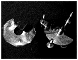
図1は、従来型の回転型コンデンサとして、エアバリコンの外観を示す図である。
図2は、従来型の回転型コンデンサとして、ポリバリコンの外観を示す図である。
図3A及び図3Bは、回転体へ電力を送る手法として従来から用いられているものを示す図である。FIG. 1 is a diagram showing the appearance of an air variable capacitor as a conventional rotary condenser.
FIG. 2 is a diagram showing the appearance of a polyvaricon as a conventional rotary capacitor.
3A and 3B are diagrams showing what has been conventionally used as a method of transmitting electric power to a rotating body.
(基本構造)
図1及び図2に示すこれら従来型の回転型コンデンサは、ラジオ等の共振回路の共振周波数を可変するために用いられている。このため、手動で回し、キャパシタンスを変化させることを目的としている。おおよその容量は、両者ともに、数百pFの容量を有している。即ち、これら従来型の回転型コンデンサは、いずれも信号の同調等に用いられるものであり、電力の伝送を行うものではない。例えば、図1に示すエアバリコンは、機械的精度でステータ側とロータ側電極の隙間を維持しているため、隙間を狭くして大容量化するには限界がある。また、図2に示すポリバリコンは、フィルムを電極間に挟んで電極間隔を維持している。このため、小型に製作することが可能になる。ただし、高速回転用途には向かない。これは、フィルムと電極間の摩擦劣化により性能が維持できないからである。
また、回転体へ電力を送る手法として、1900年代に発案された、ステータ側円盤電極とロータ側円盤電極とを多層に配置して回転可能な接合容量を形成する手法がある。しかしながら、この手法を実用化させるためには、実用的なキャパシタンスを完全非接触の状態で実現させなければならないという課題が伴う。この課題を解決するための手法としては、図3A及び図3Bに示すウィスコンシン大学により提案されたものがある。ただし、図3A及び図3Bに示す手法では、電極板間に空気を流して間隔を形成させる手法を採用しているため、外部にポンプを設けなければならないとともに、稼働するためのエネルギーを確保しなければならない。このため、実用化のために要するコストが増大してしまう。(Basic structure)
These conventional rotary capacitors shown in FIGS. 1 and 2 are used to change the resonance frequency of a resonance circuit such as a radio. Therefore, the purpose is to change the capacitance by turning it manually. Both have a capacity of several hundred pF. That is, all of these conventional rotary capacitors are used for signal tuning and the like, and do not transmit electric power. For example, since the air variable capacitor shown in FIG. 1 maintains the gap between the stator side and rotor side electrodes with mechanical accuracy, there is a limit to narrowing the gap and increasing the capacity. Further, in the polyvaricon shown in FIG. 2, a film is sandwiched between the electrodes to maintain the electrode spacing. Therefore, it can be manufactured in a small size. However, it is not suitable for high-speed rotation applications. This is because the performance cannot be maintained due to frictional deterioration between the film and the electrode.
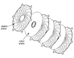
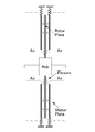
Further, as a method of transmitting electric power to a rotating body, there is a method proposed in the 1900s in which a stator side disk electrode and a rotor side disk electrode are arranged in multiple layers to form a rotatable junction capacitance. However, in order to put this method into practical use, there is a problem that a practical capacitance must be realized in a completely non-contact state. As a method for solving this problem, there is a method proposed by the University of Wisconsin shown in FIGS. 3A and 3B. However, in the methods shown in FIGS. 3A and 3B, since the method of flowing air between the electrode plates to form an interval is adopted, an external pump must be provided and energy for operation is secured. There must be. Therefore, the cost required for practical use increases.
図4は、電界結合方式による非接触給電の基本的な回路図である。 FIG. 4 is a basic circuit diagram of non-contact power feeding by the electric field coupling method.
図4に示すように、送電部1側の高周波電源Vfから出力された電力を、2つの接合容量Ccを介して、受電部2側の負荷Rに送電する。ここで、接合容量Ccは、金属板の対であるため、一方の電極を他方の電極に対してスライドさせたり、回転させたりすることにより、リニア系または回転系への電力供給が可能になる。なお、本発明は、回転系への電力供給であるため、回転させることができる接合容量Ccについて説明する。
As shown in FIG. 4, the electric power output from the high-frequency power supply Vf on the
図5は、ステータ電極ユニット11と、ロータ電極ユニット21とからなる回転電極ユニット100の構造を示す平面図及び側面断面図である。
FIG. 5 is a plan view and a side sectional view showing the structure of the
図5に示すように、回転電極ユニット100は、1つの接合容量Ccの一方をステータ電極ユニット11とし、他方をロータ電極ユニット21とするとともに、複数のステータ電極ユニット11と複数のロータ電極ユニット21とからなる多層構造の電極ユニットとなっている。多層構造とすることにより、大きな接合容量Ccを確保することができる。具体的には、5層のドーナツ状のステータ電極ユニット11の間に、4枚のロータ電極ユニット21がそれぞれ挟み込まれた構造となっており、ステータ電極ユニット11が固定され、ロータ電極ユニット21が回転する。なお、図5には、説明を簡略化させるために軸受やカバー等は記載されておらず、電極のみが記載されている。
As shown in FIG. 5, in the
図6A及び図6Bは、回転電極ユニットの基本体構造を示す斜視図である。 6A and 6B are perspective views showing the basic structure of the rotating electrode unit.
図6Aは、ロータ電極ユニット21を構成するロータスペーサ211とロータ電極212とを結合させる前の状態を示す図である。
図6Bは、ロータスペーサ211とロータ電極212とを結合させた後の状態を示す図である。
即ち、図3A及び図3Bに示すように、ロータ電極212となるリング状の極薄金属板に対して、ロータスペーサ211となる金属リングを同心円状に固定することによりロータ電極ユニット21となる。FIG. 6A is a diagram showing a state before the
FIG. 6B is a diagram showing a state after the
That is, as shown in FIGS. 3A and 3B, the
図7A及び図7Bは、ロータ電極ユニット21の周囲にステータスペーサ111を配置した状態を示す斜視図である。
7A and 7B are perspective views showing a state in which the
図7Aは、ロータ電極ユニット21とステータスペーサ111とを組み合わせる前の状態を示す図である。
図7Bは、ロータ電極ユニット21とステータスペーサ111とを組み合わせた後の状態を示す図である。
即ち、図7A及び図7Bに示すように、ロータ電極ユニット21の周囲にステータスペーサ111を配置する。FIG. 7A is a diagram showing a state before combining the
FIG. 7B is a diagram showing a state after the
That is, as shown in FIGS. 7A and 7B, the
図8A及び図8Bは、ロータ電極ユニット21とステータスペーサ111との組み合わせの上下に、ステータ電極112を張り付けて結合させることにより、回転電極ユニット100とした場合を示す斜視図である。
8A and 8B are perspective views showing a case where the
図8Aは、ロータ電極ユニット21とステータスペーサ111との組み合わせの上下に、ステータ電極112を張り付けて結合させる前の状態を示す図である。
図8Bは、ロータ電極ユニット21とステータスペーサ111を組み合わせた物の上下に、ステータ電極112を張り付けて結合させた後の状態を示す図である。即ち、図8Bに示すように、ロータ電極ユニット21とステータスペーサ111との組み合わせの上下に、ステータ電極112を張り付けて結合させることにより、回転電極ユニット100となる。
なお、図6A乃至図8Bに示す例では、説明の都合上、ユニット毎に製作しているが、製造過程では、これら部品を積層し、上下方向に圧接した後にレーザー溶接等で端部を溶接することにより一体化させる。さらに、図8A及び図8Bに示す例では、1枚のロータ電極ユニット21を2枚のステータ電極で上下から挟む構造となっているが、これらを多層に積層したものが回転電極ユニット100である。以上のような手法により軽量かつ薄型の回転電極ユニット100を製造することができる。FIG. 8A is a diagram showing a state before the
FIG. 8B is a diagram showing a state after the
In the examples shown in FIGS. 6A to 8B, each unit is manufactured for convenience of explanation, but in the manufacturing process, these parts are laminated, pressure-welded in the vertical direction, and then the end portion is welded by laser welding or the like. By doing so, it is integrated. Further, in the examples shown in FIGS. 8A and 8B, one
本実施形態における電力伝送システムは、上述した在来型の回転型コンデンサを根本的に改良したものであり、何回転でも高速回転可能な回転型電極によって接合容量Ccを形成させる。また、電力伝送用の回転電極として接合容量Ccを増大させることができる。接合容量Ccを増大させることができると、所定の電力を送電するにあたり、インバータの周波数や送電電圧を低い値に設定することが可能になる。逆に言えば、大きな電力を送電することを目的としたとき、極めて高い周波数のインバータ等を必要とせず、現行の周波数のインバータを使用することができるため、コストを低減することができる。また、送電電圧を低く設定することもできる。
以下、本実施形態の電力伝送システムの詳細について説明する。The power transmission system in the present embodiment is a fundamental improvement of the conventional rotary capacitor described above, and a junction capacitance Cc is formed by a rotary electrode capable of rotating at high speed at any number of rotations. Further, the junction capacitance Cc can be increased as a rotating electrode for power transmission. If the junction capacitance Cc can be increased, it becomes possible to set the frequency of the inverter and the transmission voltage to low values when transmitting a predetermined electric power. Conversely, when the purpose is to transmit a large amount of electric power, an inverter having an extremely high frequency or the like is not required, and an inverter having the current frequency can be used, so that the cost can be reduced. It is also possible to set the transmission voltage low.
Hereinafter, the details of the power transmission system of the present embodiment will be described.
図9は、2つの回転電極ユニット100を連結させて、回転体としてのシャフト200に電力を伝送させる場合を示す斜視図である。
FIG. 9 is a perspective view showing a case where two
回転電極ユニット100を用いて図4の回路を作成するためには、図9に示すように、回転電極ユニット100を2セット用意する必要がある。
2つの回転電極ユニット100を平行かつ同心円状に配置し、絶縁性材料300を用いて、回転電極ユニット100を、回転体としてのシャフト200に結合させる。個々の回転電極ユニット100からシャフト200上の負荷Rに対して配線する。その一方で、2つのステータ電極ユニット11の間に、高周波電源Vfによる高周波電圧を印可する。これにより、ステータ電極ユニット11側からロータ電極ユニット21側に対し送電することが可能となる。
これに対して、ロータ電極ユニット21側で得られる電力をステータ電極ユニット11側に送電するためには、高周波電源Vfと負荷Rとの位置関係を逆にすればよい。In order to create the circuit of FIG. 4 using the
The two
On the other hand, in order to transmit the electric power obtained on the
(回転型電極の問題点)
次に、図10A及び図10Bを参照して、上述した手法により製造された回転電極ユニット100における問題点について説明する。
図10A及び図10Bは、図6A乃至図8Bに示す手法により製造された回転電極ユニット100の問題点を示す断面拡大図である。(Problems with rotary electrodes)
Next, problems in the
10A and 10B are enlarged cross-sectional views showing problems of the
回転電極ユニット100の接合容量Ccを大きくするためには、電極対を形成しているステータ電極112とロータ電極212とのそれぞれの半径を長くしたり、ステータ電極122とロータ電極212との間の距離(以下、「電極間隔」と呼ぶ)が狭くなるように両者を接近させたりする手法がある。
具体的には、図10Aに示すように、ステータ電極112とロータ電極212とが対向する部分の長さrを長くしたり、ステータ電極112間の距離dを狭くしたりする手法が考えられる。
例えば、ステータ電極112間の距離dを0.5mm、ステータ電極112の半径を150mm、ロータスペーサ211の半径を50mmとすると、ステータ電極112とロータ電極212とが対向する部分の長さrは、約100mmになる。この場合、ロータ電極212の厚さが0.1mmとすると、ロータ電極212の上下の電極間隔は、それぞれ0.2mmとなる。In order to increase the junction capacitance Cc of the
Specifically, as shown in FIG. 10A, a method of increasing the length r of the portion where the
For example, assuming that the distance d between the
しかしながら、このような装置を製作するためには、機械的に高い精度が求められるため、多大なコストを要することになる。特に、ステータ電極112とロータ電極212とが対向している部分の長さrを長くする場合には、狭い電極間距離の中央付近にロータ電極212を配置する必要があるため、技術的に極めて高い精度が要求されることとなる。このため、製造コストが上がり、維持管理も容易ではなくなる。さらに、使用時の経年変化、温度による金属板の湾曲等を考慮すると、非接触状態を維持することは困難である。
なお、ステータ電極112とロータ電極212とが対向している部分の長さrを長くした場合であっても、対向するステータ電極112間の距離dが大きくなってしまうのであれば、結果的に接合容量Ccの増大は望めなくなる。However, in order to manufacture such a device, high precision is required mechanically, which requires a great deal of cost. In particular, when increasing the length r of the portion where the
Even when the length r of the portion where the
さらに、図10Aに示すように、ロータ電極212は、中心部のみで保持されているため、重力Gの影響で外周部に垂れ下がりDが生じてしまう。一方、ステータ電極112は、周囲が固定されているため、垂れ下がりDの度合はロータ電極212よりは少ないが、重力Gの影響で僅かに外周部に垂れ下がりDが生じてしまう。
Further, as shown in FIG. 10A, since the
この問題に対しては、これら電極(ロータ電極212及びステータ電極112)の厚さを厚くすることで、垂れ下がりの度合を小さくすることもできる。例えば、電極を剛体の厚板で製作することも可能である。しかしながら、重量が増してしまうし、コストもかかってしまう。また、砂粒が混入すれば、電極を傷つけることにもつながる。
また、図10Aに示すように、電極同士が(即ち、ロータ電極212とステータ電極112とが)接触する部分Tがあると、ショートしてしまう。なお、ショートを防ぐために、電極に絶縁層をコーティングしたとしても、長い時間電極を回転させ続けていると、いずれはコーティングが剥がれてしまう。このため、電極同士が接触してショートしてしまう。ショートすれば、特定の部位に大電流が流れ、電極が破損してしまう。また、ショートする直前には放電して電極が解けることもあり得る。これにより、コンデンサとしての機能が果たせなくなる。To solve this problem, the degree of sagging can be reduced by increasing the thickness of these electrodes (
Further, as shown in FIG. 10A, if there is a portion T in which the electrodes come into contact with each other (that is, the
このような問題を解消するための手法として、図10Bに示すように、電極間に流体Fを流す手法が考えられる。流体Fには、水やオイルなどの液体、空気やガスなどの気体が含まれる。
しかしながら、この手法を用いた場合、次の(1)乃至(4)の問題が生ずる。即ち、(1)流体Fを流すためにポンプが必要になるため、容積及びコストが増大してしまう。(2)流体を循環させるための帰還路を周辺に作る必要があるため、システムの容積が大きくなってしまう。(3)電極板の積層数が増大するに従い、流体を流す為の抵抗が増大するため、外部にポンプを用意する必要がある。しかし、ポンプ圧を高めると、その圧力でステータ電極112に膨らみSが生じてしまう。膨らみSを防ぐためには最外殻のステータ電極112を厚くして強度を上げる必要がある。つまり、装置が大型化してしまう。
(4)流体に粘性がある場合には、ロータの回転トルクが増大してしまう。As a method for solving such a problem, as shown in FIG. 10B, a method of flowing a fluid F between the electrodes can be considered. The fluid F includes a liquid such as water and oil, and a gas such as air and gas.
However, when this method is used, the following problems (1) to (4) occur. That is, (1) a pump is required to flow the fluid F, which increases the volume and cost. (2) Since it is necessary to create a return path for circulating the fluid in the periphery, the volume of the system becomes large. (3) As the number of laminated electrode plates increases, the resistance for flowing the fluid increases, so it is necessary to prepare an external pump. However, when the pump pressure is increased, the pressure causes the
(4) If the fluid is viscous, the rotational torque of the rotor will increase.
(問題点を解決するための具体的手法)
次に、図11A及び図11Bを参照して、上述の問題を解決するための手法について説明する。
図11A及び図11Bは、ステータ電極112及びロータ電極212のそれぞれの端部の先に、磁石Mを配置した状態を示す断面拡大図である。(Specific method for solving problems)
Next, a method for solving the above-mentioned problem will be described with reference to FIGS. 11A and 11B.
11A and 11B are enlarged cross-sectional views showing a state in which the magnet M is arranged at the tip of each end of the
図11Aは、ステータスペーサ111に配置した磁石Mの磁力を利用してロータ電極212の端部を吸引するとともに、ロータスペーサ211に配置した磁石Mの磁力を利用してステータ電極112の端部を吸引する、双方向吸引方式を示す図である。
図11Bは、ステータスペーサ111に配置した磁石Mの磁力を利用してロータ電極212の端部のみを吸引する片方向吸引方式を示す図である。
図11A及び図11Bに示すように、電極の端部を磁石Mで引っ張ることで、重力Gの影響による電極の垂れ下がりDの問題を解決することができる。なお、電極全体を強磁性体で構成させてもよいし、電極の外周部のみを強磁性体で構成させて、他の部分は非磁性体で構成させてもよい。また、磁石Mは、永久磁石でもよいし、電気磁石でもよい。永久磁石と電気磁石とを組み合わせてもよい。なお、強磁性体として何を採用するかは特に限定されず、鉄、コバルト、ニッケル等を採用することができる。In FIG. 11A, the magnetic force of the magnet M arranged on the
FIG. 11B is a diagram showing a one-way suction method in which only the end portion of the
As shown in FIGS. 11A and 11B, by pulling the end portion of the electrode with the magnet M, the problem of the hanging D of the electrode due to the influence of gravity G can be solved. The entire electrode may be made of a ferromagnet, or only the outer peripheral portion of the electrode may be made of a ferromagnet, and the other parts may be made of a non-magnetic material. Further, the magnet M may be a permanent magnet or an electric magnet. Permanent magnets and electric magnets may be combined. It should be noted that what is adopted as the ferromagnet is not particularly limited, and iron, cobalt, nickel and the like can be adopted.
図12A及び図12Bは、ステータ電極の周囲、及びロータ電極212の周囲に磁石Mを配置する場合における他の例を示す断面拡大図である。
12A and 12B are enlarged cross-sectional views showing another example in the case where the magnet M is arranged around the stator electrode and around the
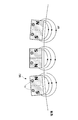
図12Aは、ロータ電極212と、ステータ電極112とを極薄の強磁性体で構成させ、ロータスペーサ211及びステータスペーサ111も強磁性体で構成させ、ステータ側とロータ側との間に磁路が形成されるように、極性を考慮して磁石Mを配置した場合を示す図である。ロータスペーサ211側に配置された磁石Mのうち、ステータ電極112に対向する面とは反対側の面に強磁性体Vが配置されている。また同様に、ステータスペーサ111側に配置された磁石Mのうち、ロータ電極212に対向する面とは反対側の面に強磁性体Vが配置されている。このように、電極を引っ張る磁石Mの面とは反対側の面に強磁性体Vを配置することは、磁気回路を構成する点で有効となる。この点については、後述する図12Bに示す例においても同様である。
In FIG. 12A, the
図12Bは、ロータ側全体がオフセット(Offset)するような事態が生じた場合を示す図である。このような場合、ステータ電極112も極薄金属で構成されているため、電極同士が接触しないようにすることができる。ただし、ステータ電極112は、容易に変形しない構成となっているため、弾性変形の範囲を超える場合には、より大きな弾性変形が可能となるように、ステータ電極112に切れ目や折り目(図示なし)を予め入れておいてもよい。
なお、図12A及び図12Bに示す例の場合、ロータ電極212及びステータ電極112が強磁性体であることが必要となるが、電極に極めて薄い金属を用いる場合には、磁気抵抗が大きくなるため、磁路を考えることができない。このため、磁石Mの極性はステータ側とロータ側とで一致させる必要はない。さらに、ステータ内、ロータ内でも極性を考慮する必要はない。FIG. 12B is a diagram showing a case where the entire rotor side is offset (Offset). In such a case, since the
In the case of the examples shown in FIGS. 12A and 12B, the
次に、図13A及び図13Bを参照して、図11A及び図11B並びに図12A及び図12Bに示す例において採用されている構成とは異なる構成で磁石Mを配置する手法について説明する。
図13A及び図13Bは、図11A及び図11B並びに図12A及び図12Bに示す例において採用されている磁石Mとは異なる構成で磁石Mを配置する手法を示す断面図である。Next, with reference to FIGS. 13A and 13B, a method of arranging the magnet M in a configuration different from the configuration adopted in the examples shown in FIGS. 11A and 11B and FIGS. 12A and 12B will be described.
13A and 13B are cross-sectional views showing a method of arranging the magnets M in a configuration different from that of the magnets M used in the examples shown in FIGS. 11A and 11B and FIGS. 12A and 12B.
図13Aは、強磁性体からなるロータ電極212の周囲に特異な形の強磁性体切片VPを配置した場合を示す全体断面図である。
図13Bは、図13Aに示す全体断面図の右半分を拡大した図である。
図12A及び図12Bに示すように、強磁性体からなるステータ電極112及びロータ電極212のそれぞれの周囲に配置する磁石M自体を特異な形(ロータ電極212に対向する面の中央部に窪みを有する形)に加工し、さらに着磁させることも可能である。しかしながら、この場合、コストがかかるとともに、隣接する磁石Mとの間で反発力が生じ、磁石Mを配置することが困難になる。このため、図13A及び図13Bに示すように、鉄等を用いて特異な形(ロータ電極212に対向する面の中央部に窪みを有する形)に製作した強磁性体切片VPを、ロータ電極212の周辺に配置する。この場合、強磁性体切片VPは、当初は磁化されていないため、配置作業が容易になる。また、電極を引っ張る磁石Mの面とは反対側の面に強磁性体Vが配置されているため、磁気回路を構成する点で有効となる。FIG. 13A is an overall cross-sectional view showing a case where a ferromagnet section VP having a peculiar shape is arranged around a
FIG. 13B is an enlarged view of the right half of the overall cross-sectional view shown in FIG. 13A.
As shown in FIGS. 12A and 12B, the magnet M itself arranged around each of the
次に、図14を参照して、ロータ電極212の周囲に磁石Mを配置する場合の具体例について説明する。
図14は、外周部222のみが強磁性体で構成され、他の部分は非磁性体で構成されたロータ電極212の周囲に、磁石Mを配置した場合を示す平面拡大図である。Next, a specific example in which the magnet M is arranged around the
FIG. 14 is an enlarged plan view showing a case where the magnet M is arranged around the
図14に示すように、ステータスペーサ111には、強磁性体で構成されたサポート121が付けられており、このサポート121に磁石Mの一部が埋め込まれるようにして固定されている。また、磁石Mの向きは、隣接する磁石Mと逆極性となるように配置されており、ロータ電極212と磁石Mとは近接しているが接触はしていない。これにより、図14に示すような磁束Mfが形成された、強い吸引力が得られる磁気回路が構成される。即ち、磁石Mから出た磁界は、強磁性体で構成された外周部222を通って、隣接する磁石Mに入って行く。このようにして、短い磁路を形成させることで、吸引力を増大させることができる。なお、上述したように、ロータ電極212の厚さは薄く構成されているため(例えば0.1mm)、磁場を受けつつ回転するが、渦電流が極めて少ない構造になっているため、渦電流による負トルク発生は極めて小さい。
As shown in FIG. 14, a
ここで、図14の例において、ロータ電極212は、全体が強磁性体で構成されておらず、外周部222のみが強磁性体となっている。これは、以下の理由による。即ち、磁石Mにロータ電極212の端部を吸引してもらうためには、強磁性体である必要があるが、電極として動作する場合には、非磁性体である方が好ましいからである。具体的には、強磁性体は、スキンデプスが薄く、皮膜部しか電流が流れず、抵抗が増大してしまう。これを防止するためには、外周部222以外の部分を非磁性体とすることが好ましいからである。
Here, in the example of FIG. 14, the
図15は、多層電極に対応した薄い強磁性体切片VPをステータスペーサ111に差し込み、最後に磁石Mを取り付けた場合を示す平面拡大図である。
FIG. 15 is an enlarged plan view showing a case where a thin ferromagnetic section VP corresponding to a multilayer electrode is inserted into a
ロータ側は、点CRを中心に矢印の方向に回転する。図15に示すような構成とすることで、ロータ電極212を吸引する力を発揮させることができる。
ここで、磁石Mの前(ロータ電極212側)に強磁性体切片VPを配置した場合、磁石Mの吸引力が低下することがあるが、強磁性体切片VPは磁石Mよりも加工がし易い。例えば、磁石Mを薄く加工するには限界があるが、強磁性体切片VPであれば容易に薄く加工することができる。このように、磁石Mの前(ロータ電極212側)に強磁性体切片VPを配置する場合と、配置しない場合とでは、吸引力の確保、加工のし易さといった面でそれぞれメリット、デメリットがある。このため、用途に応じていずれかを選択することができる。The rotor side rotates around the point CR in the direction of the arrow. With the configuration as shown in FIG. 15, the force for attracting the
Here, when the ferromagnetic section VP is arranged in front of the magnet M (on the
図16は、ステータスペーサ111に予め強磁性体切片VPを張り付け、それを積層してゆく手法を示す平面拡大図である。
FIG. 16 is an enlarged plan view showing a method in which a ferromagnetic section VP is attached to the
図16に示すように、強磁性体切片VPを張り付けたステータスペーサ111を積層し、レーザー溶接機等で固めた後に磁石Mを取り付け、最後に、磁束Mfが効率的に形成されるように強磁性体のブリッジVBを磁石Mに取り付ける。このように、電極を引っ張る磁石Mの面とは反対側の面に強磁性体のブリッジVBが配置されると、磁気回路を構成する点で有効となる。なお、磁石Mの内部に磁束Mfを通すことで磁気経路を形成させるように磁石Mを配置した場合には、電極を引っ張る磁石Mの面とは反対側の面に強磁性体のブリッジVBを配置する必要はなくなる。
As shown in FIG. 16, the
図17A乃至図17Dは、ロータ電極212の材質の構成例を示す平面拡大図である。
17A to 17D are enlarged plan views showing a configuration example of the material of the
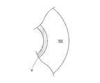
図17Aは、すべて非磁性体NVで構成させた場合を示す図である。磁石Mで吸引される必要がない場合に採用することができる構成例である。
図17Bは、すべて強磁性体Vで構成させた場合を示す図である。この場合、磁石Mで吸引されるが、送電電力が大きいとスキンデプスの影響を受ける。このため、送電電力が大きくない場合に採用することができる構成例である。
図17Cは、内側の端部のみが強磁性体Vで構成され、他の部分は非磁性体NVで構成させた場合を示す図である。ロータスペーサ211側に配置された磁石Mを用いて、ステータ電極112を吸引する場合に採用される構成例である。
図17Dは、図13A及び図13Bの例と同様に、ロータ電極212の外周部222のみを強磁性体Vで構成させ、他の部分を非磁性体NVで構成させた場合を示す図である。ステータスペーサ111側に配置された磁石Mを用いて、ロータ電極212を吸引する場合に採用される構成例である。FIG. 17A is a diagram showing a case where all of them are made of non-magnetic material NV. This is a configuration example that can be adopted when it is not necessary to be attracted by the magnet M.
FIG. 17B is a diagram showing a case where all of them are composed of the ferromagnetic material V. In this case, it is attracted by the magnet M, but if the transmitted power is large, it is affected by the skin depth. Therefore, this is a configuration example that can be adopted when the transmitted power is not large.
FIG. 17C is a diagram showing a case where only the inner end portion is composed of the ferromagnetic material V and the other portion is composed of the non-magnetic material NV. This is a configuration example adopted when the
FIG. 17D is a diagram showing a case where only the outer
図18A乃至図18Cは、吸引磁石ユニットMUと、その配列方法を示すイメージ図である。 18A to 18C are image views showing a suction magnet unit MU and a method of arranging the suction magnet unit MU.
図14乃至図16に示す例のように磁石Mを配列することもできるが、磁石Mをユニット化させた吸引磁石ユニットMUを配列させることもできる。
図18Aは、磁化方向の異なる2つの磁石を対にして使用する吸引磁石ユニットMUと、その配列手法を示す図である。この配列手法は、図18Aに示すように、電極を吸引する側とは反対側に強磁性体Vを取り付け、さらに全体を非磁性体のカバーCで覆う。これにより、回転電極ユニット100を容易に製作することができる。
図18Bは、固定穴Hが設けられた吸引磁石ユニットMUを用いた配列手法を示す図である。この配列手法は、図18Bに示すように、1つの磁石Mの磁気の方向が、非吸引電極の端面と平行になるように配列させる。このようにしても、磁気回路を形成させることができる。また、吸引磁石ユニットMUとしては、1つの部品で済むため、回転電極ユニット100をより容易に製作することができる。
なお、吸引磁石ユニットMUの配列は、隣接する吸引磁石ユニットMU間に十分な間隔を設けることができれば極性を考慮する必要はない。これに対して、吸引磁石ユニットU同士を近接させる場合には、図18Cに示すように、隣接する吸引磁石ユニットMUは、同極同士が隣り合うように配列させることで大きな吸引力を得ることができる。The magnets M can be arranged as in the examples shown in FIGS. 14 to 16, but the attractive magnet unit MU in which the magnet M is unitized can also be arranged.
FIG. 18A is a diagram showing an attractive magnet unit MU that uses two magnets having different magnetization directions as a pair and an arrangement method thereof. In this arrangement method, as shown in FIG. 18A, the ferromagnetic material V is attached to the side opposite to the side where the electrode is attracted, and the entire surface is covered with a non-magnetic material cover C. Thereby, the
FIG. 18B is a diagram showing an arrangement method using a suction magnet unit MU provided with a fixing hole H. In this arrangement method, as shown in FIG. 18B, the magnetic direction of one magnet M is arranged so as to be parallel to the end face of the non-suction electrode. Even in this way, the magnetic circuit can be formed. Further, since the suction magnet unit MU requires only one component, the rotating
It should be noted that the arrangement of the attractive magnet units MU does not need to consider the polarity as long as a sufficient distance can be provided between the adjacent attractive magnet units MUs. On the other hand, when the attractive magnet units U are brought close to each other, as shown in FIG. 18C, the adjacent attractive magnet units MU are arranged so that the same poles are adjacent to each other to obtain a large attractive force. Can be done.
図19A乃至図19Dは、磁石ベルトMBと、その使用方法を示す図である。 19A to 19D are diagrams showing the magnet belt MB and how to use the magnet belt MB.
図19Aは、磁石ベルトMBの構成を示す平面図である。
図18A乃至図18Cに示すように吸引磁石ユニットMUを配列することもできるが、磁極の配列を考慮して配置した磁石Mをベルト状にした磁石ベルトMBを配列させることもできる。具体的には、図19Aに示すように、磁極の配列を考慮して配置した磁石Mを、やや硬質でありながらも湾曲可能な非磁性かつ絶縁性の材料Eでモールドすることで磁石ベルトMBを製作する。これにより、製作する回転電極ユニット100の半径に変更が生じたとしても、変更に応じて磁石ベルトMBを曲げて対応することができるので、個別の部品を製作する必要がなくなる。また、図18A乃至図18Cの吸引磁石ユニットMUの配列のように極性を確認しながら配列してゆくような手間を省くことができる。これにより、回転電極ユニット100をさらに容易に製作することができる。
なお、磁石ベルトMBを製作するためにモールドする材料Eは特に限定されない。例えば、ナイロン系またはビニル系の材料Eを用いて磁石ベルトMBを製作することができる。また、具体的なモールドの手法も特に限定されない。例えば、磁石Mをアラミド又はケブラー等の強度のある繊維で編んだ網の中に入れて、ナイロン等の樹脂でモールドすることもできる。FIG. 19A is a plan view showing the configuration of the magnet belt MB.
As shown in FIGS. 18A to 18C, the attractive magnet units MU can be arranged, but the magnet belt MB in which the magnets M arranged in consideration of the arrangement of the magnetic poles can be arranged in a belt shape can also be arranged. Specifically, as shown in FIG. 19A, the magnet M arranged in consideration of the arrangement of the magnetic poles is molded with a non-magnetic and insulating material E that is slightly rigid but bendable, so that the magnet belt MB To make. As a result, even if the radius of the
The material E to be molded for manufacturing the magnet belt MB is not particularly limited. For example, a magnet belt MB can be manufactured using a nylon-based or vinyl-based material E. Further, the specific molding method is not particularly limited. For example, the magnet M can be placed in a net woven with strong fibers such as aramid or Kevlar and molded with a resin such as nylon.
図19Bは、磁石ベルトMBを湾曲させた状態を示す平面図である。なお、図19Bに示す磁石ベルトMBは、ステータスペーサ111側に配列させる構成となっているが、曲げる方向を逆にすれば、ロータスペーサ211側に配列させる構成とすることができる。
ここで、モールドする材料Eが比較的固いために、容易に湾曲させることができない場合があるが、図19A乃至図19Dに示すようにスリットJを設けることで容易に湾曲させることができる。ただし、スリットJを設けるか否かは任意であり必須ではない。FIG. 19B is a plan view showing a state in which the magnet belt MB is curved. The magnet belts MB shown in FIG. 19B are arranged on the
Here, since the material E to be molded is relatively hard, it may not be easily curved, but it can be easily curved by providing the slit J as shown in FIGS. 19A to 19D. However, whether or not the slit J is provided is optional and not essential.
図19Cは、磁石ベルトMBを積層させて、ベルト押さえLで固定させた状態を示す断面拡大図である。図19Cに示すように、溝Kにベルト押さえLの一部分を食い込ませて、ステータスペーサ111を用いて、必要な段数だけ積層する。これにより、磁石Mの配置の機械的な精度を保持することができる。
FIG. 19C is an enlarged cross-sectional view showing a state in which magnet belts MB are laminated and fixed by a belt retainer L. As shown in FIG. 19C, a part of the belt retainer L is made to bite into the groove K, and a required number of stages are laminated using the
図19Dは、磁石ベルトMBを積層させて、ベルト押さえLで固定させたときに、ベルト押さえがない部分の状態を示す断面拡大図である。図19Dに示すように、ベルト押さえLがない部分では、磁石ベルトMBの間に、非磁性のステータ電極112を差し込んで、ステータスペーサ111を用いて、必要な段数だけ積み重ねてネジNで固定する。
FIG. 19D is an enlarged cross-sectional view showing a state where there is no belt retainer when the magnet belts MB are laminated and fixed by the belt retainer L. As shown in FIG. 19D, in the portion where the belt retainer L is not provided, the
図20A及び図20Bは、磁石Mの端面形状を示す断面拡大図である。 20A and 20B are enlarged cross-sectional views showing the shape of the end face of the magnet M.
磁石Mに強磁性体Vの電極(例えばロータ電極212)が近づくと、磁石吸引面に垂直に働く吸引力と、磁石Mの中心に強磁性体Vの電極(例えばロータ電極212)を位置させる向心力との2つの力が働く。この2つの力が大きく働くのは、図20Bに示すような、凹面構造の場合である。これに対して、図20Aに示す平面構造の場合には、凹面構造のように上述の2つの力(吸引力及び向心力)が大きく働くことはないが、加工するための製作コストがかからないというメリットがある。なお、磁石Mの端面形状を凸面にした場合には、上述の2つの力(吸引力及び向心力)はいずれも低い値となった。 When the electrode of the ferromagnetic material V (for example, the rotor electrode 212) approaches the magnet M, the attractive force acting perpendicularly to the magnet attraction surface and the electrode of the ferromagnetic material V (for example, the rotor electrode 212) are positioned at the center of the magnet M. Two forces, centripetal force, work. These two forces work significantly in the case of a concave structure as shown in FIG. 20B. On the other hand, in the case of the planar structure shown in FIG. 20A, unlike the concave structure, the above-mentioned two forces (suction force and centripetal force) do not work significantly, but there is an advantage that the manufacturing cost for processing is not required. There is. When the end face shape of the magnet M was made convex, both of the above two forces (attractive force and centripetal force) were low values.
図21A乃至図21Cは、電極間に流体を含侵させた状態を示す断面拡大図である。 21A to 21C are enlarged cross-sectional views showing a state in which a fluid is impregnated between the electrodes.
図10A及び図10Bに示すように、電極間に流体Fを流す技術は既に存在する。しかしながら、流体Fを封止する技術は存在しない。なお、流体Fは特に限定されない。例えば、オイル、水等がある。オイルとしては、シリコンオイル等を採用することができる。また、水は、比誘電率が80であり、極めて大きな接合容量Ccを形成させることができる流体Fである。ただし、損失もあるため、送電電力を大きくしなければならない場合は注意が必要である。シリコンオイルは、比誘電率が2.8程度であるが、極寒から高温まで耐えることができ、誘電損失も小さいので、大電力を送電する場合に適した流体Fであるといえる。また、シリコンオイルは、絶縁破壊電圧が高く、潤滑性もあるため、回転系に適した流体Fである。さらに、低粘度のシリコンオイルを採用することで高速回転にも対応できる。これに対し、高粘度のシリコンオイルを採用することでダンパー機能を持たせることができる。 As shown in FIGS. 10A and 10B, there is already a technique for flowing the fluid F between the electrodes. However, there is no technique for sealing the fluid F. The fluid F is not particularly limited. For example, there are oil, water and the like. As the oil, silicon oil or the like can be adopted. Further, water is a fluid F having a relative permittivity of 80 and capable of forming an extremely large junction capacitance Cc. However, since there is a loss, care must be taken when the transmitted power must be increased. Silicone oil has a relative permittivity of about 2.8, but can withstand extremely cold to high temperatures and has a small dielectric loss, so it can be said that it is a fluid F suitable for transmitting a large amount of electric power. Further, silicone oil is a fluid F suitable for a rotating system because it has a high dielectric breakdown voltage and also has lubricity. Furthermore, by adopting low-viscosity silicone oil, it can support high-speed rotation. On the other hand, by adopting high-viscosity silicone oil, it is possible to have a damper function.
しかしながら、電極間に含侵させる流体Fに水又はオイルを採用する場合、漏洩の問題が生じるが、以下のように解決することができる。
例えば、図21Aに示すように、金属表面を親水性または親油性にする。これにより、表面張力を大きくすることができるので、シールすることなくオイルを封止することができる。However, when water or oil is used for the fluid F impregnated between the electrodes, the problem of leakage occurs, which can be solved as follows.
For example, as shown in FIG. 21A, the metal surface is made hydrophilic or lipophilic. As a result, the surface tension can be increased, so that the oil can be sealed without sealing.
また、図21Bに示すように、リング状のシールリングIを用いる。これにより、流体Fの出入口となる電極間の隙間を封止することができる。なお、シールリングIの材質は特に限定されず、例えばゴム製のシールを用いることができる。
これらの解決手法の他に、次の3つの手法によって流体Fの漏洩を防ぐことができる。即ち、1つ目として、流体Fがオイルである場合には、フェルトのような絶縁性を有するメッシュ材にグリースを混ぜて、多層電極の上下端部にリング状に固定する。これによりオイル漏れを防ぐことができる。2つ目として、メッシュ材に、増ちょう剤を混合する方法である。また、メッシュ部分でオイルの粘度を自動的に上昇させてグリース化し、そのグリースをメッシュ材で保持する方法もある。3つ目は、流体Fがシリコンオイルである場合には、メッシュ素材に鉛、セレンまたはテルル等を混ぜて、メッシュ部分に浸透した状態にあるシリコンオイルをゲル化させる。ゲル化されたシリコンオイルは、メッシュ部に定位させられる。これにより、シリコンオイルの漏洩を防ぐことができる。Further, as shown in FIG. 21B, a ring-shaped seal ring I is used. Thereby, the gap between the electrodes serving as the inlet and outlet of the fluid F can be sealed. The material of the seal ring I is not particularly limited, and for example, a rubber seal can be used.
In addition to these solution methods, the leakage of the fluid F can be prevented by the following three methods. That is, first, when the fluid F is oil, grease is mixed with a mesh material having an insulating property such as felt, and the fluid F is fixed in a ring shape to the upper and lower ends of the multilayer electrode. This can prevent oil leakage. The second method is to mix a thickener with the mesh material. There is also a method in which the viscosity of the oil is automatically increased in the mesh portion to make it grease, and the grease is held by the mesh material. Third, when the fluid F is silicone oil, lead, selenium, tellurium, or the like is mixed with the mesh material to gel the silicone oil that has permeated the mesh portion. The gelled silicone oil is localized on the mesh portion. As a result, leakage of silicone oil can be prevented.
また、図21Cに示すように、リング磁石RMをステータ電極112の外部に配置する。これにより、磁性流体MFを用いて、ステータ電極112とロータ電極212間の磁束に沿って流体Fの漏洩を封止することができる。
なお、磁性流体MFとして何を採用するかについては特に限定されない。例えば水に混ざらない油をベースとしたものに混ぜることもできる。この場合、水を封止することもできる。さらに、フッ素油をベースとした磁性流体MFは、フッ素油がシリコンオイルと混合しない性質を利用してシリコンオイルの封止にも使用することができる。ここで、フッ素油は、蒸気圧が極めて低いため、長期間使用しても磁性流体部が細ることがない。真空用途でも使用することができる。Further, as shown in FIG. 21C, the ring magnet RM is arranged outside the
It should be noted that what is adopted as the magnetic fluid MF is not particularly limited. For example, it can be mixed with an oil-based product that is immiscible with water. In this case, water can also be sealed. Further, the ferrofluid MF based on fluorine oil can also be used for sealing silicon oil by utilizing the property that fluorine oil does not mix with silicon oil. Here, since the vapor pressure of the fluorine oil is extremely low, the magnetic fluid portion does not become thin even if it is used for a long period of time. It can also be used in vacuum applications.
なお、図21A乃至図21Cでは、磁性流体用の磁石リングRMを1つ(つまり上下で2つ)置いているが、同心円状に半径を違えた磁石リングRMを多段に配置することもできる。また、段数を増やすことで封止圧力を高めることもできる。図21A乃至図21Cにおいて、ロータ電極212等を吸引している磁石Mは、常時設置してもよいし、製造時のオイル封入時のみに用い、以後はオイルによって電極間を離隔する方式を採用してもよい。この際、シリコンオイルには離型性があるため、電極同士が密着することを妨げることができる。さらに、オイル中に球状粒子(シリカ、フラーレン等)を混合させることで潤滑性を高めてもよい。
In addition, in FIGS. 21A to 21C, one magnet ring RM for magnetic fluid is placed (that is, two magnet rings RM in the upper and lower sides), but magnet ring RMs having different radii concentrically can be arranged in multiple stages. Further, the sealing pressure can be increased by increasing the number of stages. In FIGS. 21A to 21C, the magnet M attracting the
図22A乃至図22Cは、熱交換器Pの熱交換機能を持たせた回転電極ユニット100の例を示す断面拡大図である。
22A to 22C are enlarged cross-sectional views showing an example of the
図22A乃至図22Cは、いずれも図21A乃至図21Cと同様に、電極間に流体FとしてのオイルOを含侵させ、表面張力を利用したり(図22A)、必要に応じてシールリング(オイルシールリングQ)を用いて封止したりする(図22B)点は同じである。ただし、オイルとして、熱伝導性オイルを使用することにより、回転電極ユニット100をヒートシンクとしても利用することもできる。
In FIGS. 22A to 22C, similarly to FIGS. 21A to 21C, oil O as a fluid F is impregnated between the electrodes to utilize surface tension (FIG. 22A), and if necessary, a seal ring (FIG. 22A). The point of sealing with the oil seal ring Q) (FIG. 22B) is the same. However, by using the heat conductive oil as the oil, the rotating
図22Cは、ステータ電極112の外側に、冷却水Wで冷却可能な熱交換リング磁石RMを配置した状態を示している。これにより、熱源Xからの熱エネルギーによりロータ内部が発熱したとしても、その熱を外部に逃がすことができる。逆に、外部から温水(図示せず)を用いてロータ内部を最適な温度に調節することもできる。
FIG. 22C shows a state in which the heat exchange ring magnet RM that can be cooled by the cooling water W is arranged outside the
上述したように、電界結合用の回転電極で形成される接合容量Ccを増大させるために、磁石Mで電極を吸引することにより、大面積の電極であっても、非接触性を維持することができる。このため、大型機械用または高速回転用の非接触電極を製造することができるようになる。特に、非接触性を維持させるために流体Fを流す必要がないため、ポンプ等の付属物を設置する必要がなくなり、信頼性の向上、低コスト化が実現される。これにより、回転電極ユニット100の実用性がさらに高まり、スリップリングの代替を進めて行くための大きな技術的要素となる。
As described above, in order to increase the bonding capacitance Cc formed by the rotating electrode for electric field coupling, the non-contact property is maintained even for a large-area electrode by attracting the electrode with the magnet M. Can be done. Therefore, it becomes possible to manufacture non-contact electrodes for large machines or for high-speed rotation. In particular, since it is not necessary to flow the fluid F in order to maintain non-contact, it is not necessary to install an accessory such as a pump, and reliability is improved and cost is reduced. As a result, the practicality of the
即ち、スリップリングは、接触式のため、メンテナンスが必要であり、定期的に交換する必要がある。しかし、数kWまでならば、容易に送電できる手軽さもある。これに取って代わることができる大電力送電可能なものが登場していない。
例えば、磁界式では、大電力送電時には、コイルをフェライトコアが囲んだものを対向させる構造を有するが、重く高価になるとともに、自身が発熱してしまう。
これに対して、電界結合方式は、装置自体に発熱源が無く軽量である利点はあるものの、大電力送電可能な、1nF程度の接合容量を有する回転円盤が実現できないでいた。産業で用いるためには、高信頼性が不可欠である。
本発明では、これを初めて可能とする磁石吸引電極を提案した。これにより、実用性が極めて高くなり、工業用途へ適用されてゆくと期待される。
さらに、液体含侵型、ヒートシンク型へと発展させている。これも、活用場面の拡大が期待できる。That is, since the slip ring is a contact type, maintenance is required and it is necessary to replace it regularly. However, if it is up to several kW, it is easy to transmit power. There is no alternative to this that can transmit high power.
For example, the magnetic field type has a structure in which a coil surrounded by a ferrite core is opposed to each other at the time of high power transmission, but it is heavy and expensive, and itself generates heat.
On the other hand, the electric field coupling method has an advantage that the device itself has no heat source and is lightweight, but it has not been possible to realize a rotating disk having a junction capacity of about 1 nF capable of transmitting a large amount of electric power. High reliability is indispensable for industrial use.
In the present invention, we have proposed a magnet attraction electrode that makes this possible for the first time. As a result, the practicality becomes extremely high, and it is expected that it will be applied to industrial applications.
Furthermore, it has been developed into a liquid impregnation type and a heat sink type. This can also be expected to expand the usage scene.
以上、本発明の一実施形態について説明したが、本発明は、上述の実施形態に限定されるものではなく、本発明の目的を達成できる範囲での変形、改良等は本発明に含まれるものである。 Although one embodiment of the present invention has been described above, the present invention is not limited to the above-described embodiment, and modifications, improvements, and the like within the range in which the object of the present invention can be achieved are included in the present invention. Is.
例えば、本実施形態では、ディスク型の電極について説明したが、図23に示すように、シリンダー型の電極でも、磁石Mの力を利用して、回転に伴って生じ得るシリンダーの偏心を防ぐことができる。 For example, in the present embodiment, the disc type electrode has been described, but as shown in FIG. 23, even in the cylinder type electrode, the force of the magnet M is used to prevent the eccentricity of the cylinder that may occur due to rotation. Can be done.
図23は、シリンダー型電極の場合を示す断面図である。 FIG. 23 is a cross-sectional view showing the case of a cylinder type electrode.
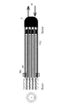
上述の例は、ディスク型の電極について説明したが、図23に示すように、シリンダー型の電極でも、磁石Mの力を利用して、回転に伴って生じ得るシリンダーの偏心を防ぐことができる。この場合には、図23に示すように、固定シャフト501側に多層のシリンダー型送電電極511を配設し、それらの電極に組み合わさるように回転シャフト502側に多層のシリンダー型受電電極521を配置させる。この際、回転シャフト502側の電極を強磁性体の極薄金属とし、固定シャフト501側の電極の底部に磁石Mを配置する。これにより、回転シャフト502側の電極の偏心を防ぐことができる。
In the above example, the disk type electrode has been described, but as shown in FIG. 23, even in the cylinder type electrode, the force of the magnet M can be used to prevent the eccentricity of the cylinder that may occur due to rotation. .. In this case, as shown in FIG. 23, a multi-layered cylinder type
また例えば、本実施形態では、ディスク型の電極について説明したが、図24に示すように、磁石Mを用いて強磁性体の極薄金属膜を吸引する方法は、リニア駆動系についても適用することができる。 Further, for example, in the present embodiment, the disk type electrode has been described, but as shown in FIG. 24, the method of attracting the ultrathin metal film of the ferromagnetic material by using the magnet M is also applied to the linear drive system. be able to.
図24は、リニア駆動系の場合を示す斜視図である。 FIG. 24 is a perspective view showing the case of a linear drive system.
図24に示すように、リニア駆動系では、送電電極601として、コの字型の電極を用意する。具体的には、2枚の送電電極601の間に固定ブロックBを配置し、コの字型になるようにネジNで固定する。送電電極601としては、非磁性体であるアルミニウムが使用される。このコの字型の送電電極601の端部に磁石Mを周期的に取り付けて磁石列Mrを形成させる。このような送電電極601内に、強磁性極薄金属の受電電極602を差し込んだ場合、最初は送電電極上を這って挿入されるが、受電電極602が磁石Mに近づくと、磁力によって吸引され、非接触状態になる。さらに、受電電極602の取り付け部(図示せず)と磁石Mの距離よりも、受電電極602の長さを僅かに短くすると、受電電極602は磁石Mにも接触しない。このようにして、極狭いコの字型の送電電極601内でも完全非接触を実現させることができる。このような状態で、線路方向Zに沿って稼働させれば、完全非接触の状態で接合容量Ccの大きなリニア駆動系を実現させることができる。
なお、図示はしないが、受電電極602の先端部に磁石Mを配列し、コの字型の固定ブロックBの中央部に強磁性体Vを配置して対向させることで、磁石Mと強磁性体Vとを逆に取り付けることもできる。As shown in FIG. 24, in the linear drive system, a U-shaped electrode is prepared as the
Although not shown, the magnet M is arranged at the tip of the
また例えば、上述の実施形態における磁石Mは、配置された状態のまま製品化され、磁力を用いて電極を永続的に吸引し続ける構成となっているが、この構成に限定されない。電力伝送システムの製造過程でのみ配置される構成とすることもできる。具体的には例えば、電界結合電力伝送技術を適用した電力伝送システムの製造方法として、ステータスペーサ111に磁石Mを配置して、ロータ電極212の外周部222を磁力で吸引する工程と、ロータ電極212とステータ電極112との間に形成された隙間に流体Fを封止する工程と、ステータスペーサ111に配置された磁石Mを取り外す工程とを含むこともできる。
これにより、製造過程でのみ磁石Mを使用し、製品になった段階で磁石Mを存在させなくすることができるので、製品の軽量化、及びコスト削減を図ることができる。Further, for example, the magnet M in the above-described embodiment is commercialized in an arranged state and has a configuration in which the electrode is permanently attracted by using a magnetic force, but the present invention is not limited to this configuration. It may be configured to be arranged only in the manufacturing process of the power transmission system. Specifically, for example, as a method of manufacturing a power transmission system to which an electric field-coupled power transmission technique is applied, a step of arranging a magnet M on a
As a result, the magnet M can be used only in the manufacturing process, and the magnet M can be eliminated at the stage of becoming a product, so that the weight of the product can be reduced and the cost can be reduced.
以上まとめると、本発明が適用される電力伝送システムは、次のような構成を取れば足り、各種各様な実施形態を取ることができる。
即ち、本発明が適用される電力伝送システムは、
1つ以上のロータ電極(例えばロータ電極212)と1つ以上のロータスペーサ(例えばロータスペーサ211)とが交互に積層されたロータ電極ユニット(例えばロータ電極ユニット21)と、1つ以上のステータ電極(例えばステータ電極112)と1つ以上のステータスペーサ(例えばステータスペーサ111)とが交互に積層されたステータ電極ユニット(例えばステータ電極ユニット11)と、からなる回転電極ユニット(例えば回転電極ユニット100)を備え、
前記回転電極ユニットは、
前記ロータ電極が送電電極(例えばステータ電極112)である場合には、前記ステータ電極が受電電極(例えばロータ電極212)であり、
前記ロータ電極が受電電極である場合には、前記ステータ電極が送電電極であり、
前記ロータ電極ユニットと前記ステータ電極ユニットとが入れ子状に組み合わせて相互に回転可能であり、
前記ロータ電極のうち少なくとも外周部(例えば外周部222)は、磁性体からなる部材で構成され、
前記ステータスペーサは、前記ロータ電極の外周部を磁力で吸引する磁石を有する。
これにより、ロータ電極の端部を磁石で引っ張ることで、重力の影響によるロータ電極の垂れ下がりの問題を解決することができるので、電極間がショートしないように回転電極の接合容量を安定的に得ることができる。その結果、接合容量を増大させることができる。Summarizing the above, the power transmission system to which the present invention is applied suffices to have the following configuration, and various various embodiments can be taken.
That is, the power transmission system to which the present invention is applied is
A rotor electrode unit (for example, rotor electrode unit 21) in which one or more rotor electrodes (for example, rotor electrode 212) and one or more rotor spacers (for example, rotor spacer 211) are alternately laminated, and one or more stator electrodes. A rotating electrode unit (for example, a rotating electrode unit 100) composed of a stator electrode unit (for example, a stator electrode unit 11) in which (for example, a stator electrode 112) and one or more stator spacers (for example, a stator spacer 111) are alternately laminated. With
The rotating electrode unit is
When the rotor electrode is a power transmission electrode (for example, a stator electrode 112), the stator electrode is a power receiving electrode (for example, a rotor electrode 212).
When the rotor electrode is a power receiving electrode, the stator electrode is a power transmission electrode.
The rotor electrode unit and the stator electrode unit can be combined in a nested manner and rotate with each other.
At least the outer peripheral portion (for example, the outer peripheral portion 222) of the rotor electrode is made of a member made of a magnetic material.
The stator spacer has a magnet that magnetically attracts the outer peripheral portion of the rotor electrode.
As a result, by pulling the end of the rotor electrode with a magnet, the problem of the rotor electrode hanging due to the influence of gravity can be solved, so that the joint capacitance of the rotating electrode can be stably obtained so that the electrodes do not short-circuit. be able to. As a result, the junction capacitance can be increased.
また、前記ロータスペーサは、前記ステータ電極の外周部を磁力で吸引する磁石を有することができる。
これにより、ロータ電極の端部を磁石で引っ張るとともに、ステータ電極の端部を磁石で引っ張ることで、重力の影響による電極の垂れ下がりの問題を解決することができる。このため、電極間がショートしないように回転電極の接合容量を安定的に得ることができる。その結果、接合容量をより増大させることができる。Further, the rotor spacer may have a magnet that magnetically attracts the outer peripheral portion of the stator electrode.
As a result, the problem of the electrode hanging due to the influence of gravity can be solved by pulling the end of the rotor electrode with a magnet and pulling the end of the stator electrode with a magnet. Therefore, the bonding capacitance of the rotating electrodes can be stably obtained so that the electrodes do not short-circuit. As a result, the bonding capacity can be further increased.
また、前記ロータ電極と前記ステータ電極との間に形成された隙間に流体(例えば流体F)が存在し、
前記流体は封止されるようにすることができる。
これにより、電極間に流体を封止することができるので、電極間がショートしないように回転電極の接合容量を安定的に得ることができる。その結果、接合容量をさらに増大させることができる。Further, a fluid (for example, fluid F) exists in the gap formed between the rotor electrode and the stator electrode.
The fluid can be sealed.
As a result, the fluid can be sealed between the electrodes, so that the bonding capacitance of the rotating electrodes can be stably obtained so that the electrodes do not short-circuit. As a result, the junction capacitance can be further increased.
また、本発明の一態様の電力伝送システムの製造方法は、
1つ以上のロータ電極と1つ以上のロータスペーサとが交互に積層されたロータ電極ユニットと、1つ以上のステータ電極と1つ以上のステータスペーサとが交互に積層されたステータ電極ユニットと、からなる回転電極ユニットを備え、前記回転電極ユニットは、前記ロータ電極が送電電極である場合には、前記ステータ電極が受電電極であり、前記ロータ電極が受電電極である場合には、前記ステータ電極が送電電極であり、前記ロータ電極ユニットと前記ステータ電極ユニットとが入れ子状に組み合わせて相互に回転可能であり、前記ロータ電極のうち少なくとも外周部は、磁性体からなる部材で構成される、電界結合電力伝送技術を適用した電力伝送システムの製造方法であって、
前記ステータスペーサに磁石を配置して、前記ロータ電極の外周部を磁力で吸引する工程と、
前記ロータ電極と前記ステータ電極との間に形成された隙間に流体を封止する工程と、
前記ステータスペーサに配置された前記磁石を取り外す工程と、
を含む。
これにより、製造過程でのみ磁石を使用し、製品になった段階で磁石を存在させなくすることができるので、製品の軽量化、及びコスト削減を図ることができる。Further, the method for manufacturing the power transmission system according to one aspect of the present invention is described.
A rotor electrode unit in which one or more rotor electrodes and one or more rotor spacers are alternately laminated, a stator electrode unit in which one or more stator electrodes and one or more stator spacers are alternately laminated, and a stator electrode unit. The rotary electrode unit comprises a rotary electrode unit comprising the above, and the rotary electrode unit comprises the stator electrode when the rotor electrode is a power transmission electrode and the stator electrode when the rotor electrode is a power receiving electrode. Is a power transmission electrode, and the rotor electrode unit and the stator electrode unit can be combined in a nested manner to rotate with each other, and at least the outer peripheral portion of the rotor electrode is an electric field made of a member made of a magnetic material. It is a manufacturing method of a power transmission system to which combined power transmission technology is applied.
A step of arranging a magnet on the stator spacer and attracting the outer peripheral portion of the rotor electrode by magnetic force.
A step of sealing the fluid in the gap formed between the rotor electrode and the stator electrode, and
The step of removing the magnet arranged on the stator spacer and
including.
As a result, the magnet can be used only in the manufacturing process, and the magnet can be eliminated at the stage of becoming a product, so that the weight of the product can be reduced and the cost can be reduced.
1:送電部、2:受電部、11:ステータ電極ユニット、21:ロータ電極ユニット、100:回転電極ユニット、112:ステータ電極、111:ステータスペーサ、121:強磁性体で構成されたサポート、200:シャフト、211:ロータスペーサ、212:ロータ電極、222:ロータ電極の外周部、300:絶縁性材料、501:回転シャフト、502:固定シャフト、511:シリンダー型送電電極、512:シリンダー型受電電極、601:送電電極、602:受電電極、B:固定ブロック、C:非磁性体のカバー、Cc:接合容量、CR:点(回転中心)、D:電極の垂れ下がり、d:ステータ電極間の距離、E:モールドする材料、F:流体、G:重力、H:固定穴、I:シールリング、i:電流、J:スリット、K:溝、L:ベルト押さえ、M:磁石、MF:磁性流体、Mf:磁束、Mr:磁石列、MU:磁石ユニット、N:ネジ、NV:非磁性体、O:オイル、P:熱交換器、Q:オイルシールリング、R:負荷、RM:リング磁石、r:ステータ電極とロータ電極とが対向している部分の長さ、S:電極の膨らみ、T:接触する部分、V:強磁性体、VB:強磁性体のブリッジ、Vf:高周波電源、VP:強磁性体切片、W:冷却水、X:熱源、Y:誘電体、Z:線路方向(稼働方向) 1: Transmission unit, 2: Power receiving unit, 11: Stator electrode unit, 21: Rotor electrode unit, 100: Rotating electrode unit, 112: Stator electrode, 111: Stator spacer, 121: Support composed of ferromagnetic material, 200 : Shaft, 211: Rotor spacer, 212: Rotor electrode, 222: Outer periphery of rotor electrode, 300: Insulating material, 501: Rotating shaft, 502: Fixed shaft, 511: Cylinder type power transmission electrode, 512: Cylinder type power receiving electrode , 601: Transmission electrode, 602: Power receiving electrode, B: Fixed block, C: Non-magnetic material cover, Cc: Bonding capacitance, CR: Point (center of rotation), D: Electrode hanging, d: Distance between stator electrodes , E: Material to be molded, F: Fluid, G: Gravity, H: Fixing hole, I: Seal ring, i: Current, J: Slit, K: Groove, L: Belt retainer, M: Magnet, MF: Magnetic fluid , Mf: magnetic flux, Mr: magnet row, MU: magnet unit, N: screw, NV: non-magnetic material, O: oil, P: heat exchanger, Q: oil seal ring, R: load, RM: ring magnet, r: Length of the portion where the stator electrode and the rotor electrode face each other, S: bulge of the electrode, T: contact portion, V: ferromagnetic material, VB: ferromagnetic bridge, Vf: high frequency power supply, VP : Ferrectic electrode section, W: Cooling water, X: Heat source, Y: Electrode, Z: Line direction (operating direction)
Claims (4)
1つ以上のロータ電極と1つ以上のロータスペーサとが交互に積層されたロータ電極ユニットと、1つ以上のステータ電極と1つ以上のステータスペーサとが交互に積層されたステータ電極ユニットと、からなる回転電極ユニットを備え、
前記回転電極ユニットは、
前記ロータ電極が送電電極である場合には、前記ステータ電極が受電電極であり、
前記ロータ電極が受電電極である場合には、前記ステータ電極が送電電極であり、
前記ロータ電極ユニットと前記ステータ電極ユニットとが入れ子状に組み合わせて相互に回転可能であり、
前記ロータ電極のうち少なくとも外周部は、磁性体からなる部材で構成され、
前記ステータスペーサは、前記ロータ電極の外周部を磁力で吸引する磁石を有する、
電力伝送システム。A power transmission system that applies electric field coupling power transmission technology.
A rotor electrode unit in which one or more rotor electrodes and one or more rotor spacers are alternately laminated, a stator electrode unit in which one or more stator electrodes and one or more stator spacers are alternately laminated, and a stator electrode unit. Equipped with a rotating electrode unit consisting of
The rotating electrode unit is
When the rotor electrode is a power transmission electrode, the stator electrode is a power receiving electrode.
When the rotor electrode is a power receiving electrode, the stator electrode is a power transmission electrode.
The rotor electrode unit and the stator electrode unit can be combined in a nested manner and rotate with each other.
At least the outer peripheral portion of the rotor electrode is made of a member made of a magnetic material.
The stator spacer has a magnet that magnetically attracts the outer peripheral portion of the rotor electrode.
Power transmission system.
請求項1に記載の電力伝送システム。The rotor spacer has a magnet that magnetically attracts the outer peripheral portion of the stator electrode.
The power transmission system according to claim 1.
前記流体は封止されている、
請求項1又は2に記載の電力伝送システム。A fluid exists in the gap formed between the rotor electrode and the stator electrode,
The fluid is sealed,
The power transmission system according to claim 1 or 2.
前記ステータスペーサに磁石を配置して、前記ロータ電極の外周部を磁力で吸引する工程と、
前記ロータ電極と前記ステータ電極との間に形成された隙間に流体を封止する工程と、
前記ステータスペーサに配置された前記磁石を取り外す工程と、
を含む、
電力伝送システムの製造方法。A rotor electrode unit in which one or more rotor electrodes and one or more rotor spacers are alternately laminated, a stator electrode unit in which one or more stator electrodes and one or more stator spacers are alternately laminated, and a stator electrode unit. The rotary electrode unit comprises a rotary electrode unit comprising the above, and the rotary electrode unit comprises the stator electrode when the rotor electrode is a power transmission electrode and the stator electrode when the rotor electrode is a power receiving electrode. Is a power transmission electrode, and the rotor electrode unit and the stator electrode unit can be combined in a nested manner to rotate with each other, and at least the outer peripheral portion of the rotor electrode is an electric field made of a member made of a magnetic material. It is a manufacturing method of a power transmission system to which combined power transmission technology is applied.
A step of arranging a magnet on the stator spacer and attracting the outer peripheral portion of the rotor electrode by magnetic force.
A step of sealing the fluid in the gap formed between the rotor electrode and the stator electrode, and
The step of removing the magnet arranged on the stator spacer and
including,
Manufacturing method of power transmission system.
Applications Claiming Priority (3)
| Application Number | Priority Date | Filing Date | Title |
|---|---|---|---|
| JP2017164589 | 2017-08-29 | ||
| JP2017164589 | 2017-08-29 | ||
| PCT/JP2018/031937 WO2019044900A1 (en) | 2017-08-29 | 2018-08-29 | Electric power transmission system, and manufacturing method for electric power transmission system |
Publications (2)
| Publication Number | Publication Date |
|---|---|
| JPWO2019044900A1 JPWO2019044900A1 (en) | 2020-09-24 |
| JP6862014B2 true JP6862014B2 (en) | 2021-04-21 |
Family
ID=65527199
Family Applications (1)
| Application Number | Title | Priority Date | Filing Date |
|---|---|---|---|
| JP2019539580A Active JP6862014B2 (en) | 2017-08-29 | 2018-08-29 | Power transmission system and manufacturing method of power transmission system |
Country Status (3)
| Country | Link |
|---|---|
| US (1) | US11289947B2 (en) |
| JP (1) | JP6862014B2 (en) |
| WO (1) | WO2019044900A1 (en) |
Families Citing this family (1)
| Publication number | Priority date | Publication date | Assignee | Title |
|---|---|---|---|---|
| CN115172002B (en) * | 2022-07-20 | 2024-11-19 | 安徽省瀚海新材料股份有限公司 | A NdFeB permanent magnet magnetizing device and method |
Family Cites Families (72)
| Publication number | Priority date | Publication date | Assignee | Title |
|---|---|---|---|---|
| US405858A (en) * | 1889-06-25 | Nikola Tesla | Magnetic Motor | |
| US2674729A (en) * | 1950-04-13 | 1954-04-06 | Edward G Martin | Measuring apparatus |
| CH353071A (en) * | 1956-11-07 | 1961-03-31 | S E A Societe D Electronique E | Rotating electric machine |
| FR77407E (en) * | 1960-03-17 | 1962-03-02 | Electronique & Automatisme Sa | Advanced rotating electrical machines |
| FR79354E (en) * | 1960-09-08 | 1962-11-23 | Electronique & Automatisme Sa | Advanced rotating electrical machines |
| US2970238A (en) * | 1959-02-12 | 1961-01-31 | Printed Motors Inc | Printed circuit armature |
| US3153165A (en) * | 1959-10-29 | 1964-10-13 | Printed Motors Inc | Electrical synchro-machines of the axial air-gap type |
| FR1259582A (en) * | 1960-03-17 | 1961-04-28 | Electronique & Automatisme Sa | Advanced Synchronous Rotating Electric Machine Device |
| FR78826E (en) * | 1960-09-08 | 1962-09-14 | Electronique & Automatisme Sa | Advanced rotating electrical machines |
| US3450919A (en) * | 1965-09-16 | 1969-06-17 | Electronique & Automatisme Sa | Multiple member windings for electrical rotating machines |
| US4187453A (en) * | 1975-01-06 | 1980-02-05 | Jim Zegeer | Electric motor drive system |
| US4115915A (en) * | 1975-07-31 | 1978-09-26 | General Electric Company | Process for manufacturing motor having windings constructed for automated assembly |
| JPS5678342A (en) * | 1979-11-26 | 1981-06-27 | Kangiyou Denki Kiki Kk | Printed circuit |
| US4645961A (en) * | 1983-04-05 | 1987-02-24 | The Charles Stark Draper Laboratory, Inc. | Dynamoelectric machine having a large magnetic gap and flexible printed circuit phase winding |
| DE3526166C2 (en) * | 1984-07-23 | 1996-05-02 | Asahi Chemical Ind | Brushless electric motor and method of manufacturing a coil unit therefor |
| CH660542A5 (en) * | 1984-08-31 | 1987-04-30 | Asgalium Sa | ELECTRIC MOTOR. |
| JPS6244056A (en) * | 1985-08-20 | 1987-02-26 | Kiyonori Fujisaki | Dc motor |
| DE3821050A1 (en) * | 1988-06-22 | 1989-12-28 | Thomson Brandt Gmbh | TACHOGENERATOR |
| FR2659178B1 (en) * | 1990-03-02 | 1992-05-15 | Ebauchesfabrik Eta Ag | DRIVING COIL ASSEMBLY, METHOD FOR MANUFACTURING SUCH AN ASSEMBLY, AND ELECTROMAGNETIC MICROMOTOR EQUIPPED WITH SAME. |
| US5942830A (en) * | 1994-04-06 | 1999-08-24 | Hill; Wolfgang | Three-phase electric machine with interlaced conductor layers |
| US6411002B1 (en) * | 1996-12-11 | 2002-06-25 | Smith Technology Development | Axial field electric machine |
| US20020163281A1 (en) * | 2001-05-04 | 2002-11-07 | Menachem Rafaelof | Thin film motors |
| US20030080631A1 (en) * | 2001-11-01 | 2003-05-01 | Nikon Corporation | Sheet coils and linear motors comprising same, and stage units and microlithography apparatus comprising said linear motors |
| PT1590871E (en) * | 2003-02-07 | 2008-08-27 | Core Motion Inc | Conductor optimized axial field rotary energy device |
| JP4145181B2 (en) * | 2003-03-28 | 2008-09-03 | オリンパス株式会社 | Electrostatic actuator and displacement method |
| US7239065B2 (en) * | 2003-07-08 | 2007-07-03 | Tibion Corporation | Electrostatic actuator with fault tolerant electrode structure |
| US7053520B2 (en) * | 2003-07-18 | 2006-05-30 | The Regents Of The University Of California | Rotational actuator or motor based on carbon nanotubes |
| KR20060079250A (en) * | 2004-03-12 | 2006-07-05 | 니텍 가부시끼가이샤 | Motor using square wave lead |
| US20060055265A1 (en) * | 2004-09-16 | 2006-03-16 | Zalusky James T | Printed circuit board motor |
| US20060214535A1 (en) * | 2005-03-22 | 2006-09-28 | Salmon Peter C | Energy converter utilizing electrostatics |
| TWI338434B (en) * | 2006-01-03 | 2011-03-01 | Delta Electronics Inc | Three phase opposite rotating motor and fan |
| GB0617989D0 (en) * | 2006-09-13 | 2006-10-18 | Denne Phillip R M | Improvements in electrical machines |
| US8558425B2 (en) * | 2006-10-26 | 2013-10-15 | Deere & Company | Motor having stator with generally planar windings |
| JP2008245356A (en) * | 2007-03-26 | 2008-10-09 | Moriyama Denki Seisakusho:Kk | Axial gap type engine driven generator |
| DE102008042967B4 (en) * | 2008-10-20 | 2017-04-06 | Robert Bosch Gmbh | Cascaded micromechanical actuator structure |
| JP4571685B2 (en) * | 2008-12-12 | 2010-10-27 | 本田技研工業株式会社 | Stator coil of axial gap type rotating electrical machine |
| CN102292897B (en) * | 2009-01-16 | 2014-04-02 | 科尔风力发电公司 | Segmented stators for axial field devices |
| JP5351640B2 (en) * | 2009-03-23 | 2013-11-27 | 日本電産セイミツ株式会社 | Flat vibration motor |
| TWI388109B (en) * | 2009-08-14 | 2013-03-01 | Metal Ind Res & Dev Ct | A stator structure and a micro motor having the stator structure and a method of manufacturing the same |
| US8193678B2 (en) * | 2009-09-07 | 2012-06-05 | Sunonwealth Electric Machine Industry Co., Ltd. | Coil unit for motor stator |
| US8729887B2 (en) * | 2009-11-09 | 2014-05-20 | Aisan Kogyo Kabushiki Kaisha | Rotation angle sensor |
| JP4699570B1 (en) * | 2009-12-22 | 2011-06-15 | 株式会社コスモメカニクス | Disc type coil |
| US8319595B2 (en) * | 2010-01-13 | 2012-11-27 | Cosmo Mechanics Co., Ltd. | Coil apparatus |
| US8154156B2 (en) * | 2010-03-16 | 2012-04-10 | Chieftek Precision Co., Ltd. | Coil assembly for linear motor |
| JP5534337B2 (en) * | 2010-09-30 | 2014-06-25 | 日立工機株式会社 | Disc motor and electric working machine |
| JP5534338B2 (en) * | 2010-09-30 | 2014-06-25 | 日立工機株式会社 | Disc motor and electric working machine |
| TWI413341B (en) * | 2010-11-12 | 2013-10-21 | Yen Sun Technology Corp | Motor stator and assembly method thereof |
| TWI399012B (en) * | 2010-11-12 | 2013-06-11 | Yen Sun Technology Corp | Motor stator |
| JP5450361B2 (en) * | 2010-11-30 | 2014-03-26 | ニスカ株式会社 | Axial gap type rotating machine and axial gap type generator |
| US8593016B2 (en) * | 2010-12-03 | 2013-11-26 | Sri International | Levitated micro-manipulator system |
| JP2012152028A (en) * | 2011-01-19 | 2012-08-09 | Denso Corp | Rotary electric machine |
| WO2013032405A1 (en) * | 2011-09-01 | 2013-03-07 | Agency For Science, Technology And Research | Data storage device |
| US9184676B2 (en) * | 2011-10-31 | 2015-11-10 | Wisconsin Alumni Research Foundation | Varying capacitance rotating electrical machine |
| WO2013122543A1 (en) * | 2012-02-13 | 2013-08-22 | Agency For Science, Technology And Research | Motor and method for assembling the same |
| US9209656B2 (en) * | 2012-05-22 | 2015-12-08 | Nidec Corporation | Brushless motor and disk drive apparatus |
| JP6075722B2 (en) | 2012-06-21 | 2017-02-08 | ハンファテクウィン株式会社Hanwha Techwin Co.,Ltd. | Work machine |
| US9530557B2 (en) * | 2012-06-21 | 2016-12-27 | Hanwha Techwin Co., Ltd. | Working machine powered in a non-contact manner |
| EP2889989A4 (en) * | 2012-08-21 | 2016-10-05 | Jie Dai | DRIVE MOTOR WITH MASTER-SLAVE FLYWHEEL |
| US20140252914A1 (en) * | 2013-03-06 | 2014-09-11 | Lawrence Livermore National Security, Llc | Electrostatic generator/motor designs capable of operation with the electrodes immersed in a liquid or pressurized gas |
| US9270203B2 (en) * | 2013-03-12 | 2016-02-23 | Lawrence Livermore National Security, Llc | Electrode geometry for electrostatic generators and motors |
| US20140262499A1 (en) * | 2013-03-14 | 2014-09-18 | Boulder Wind Power, Inc. | Methods and apparatus for optimizing electrically inoperative zones on laminated composite assemblies |
| CN105765834A (en) * | 2013-09-13 | 2016-07-13 | 瑞泽能系统公司 | PCB motor |
| JP6322391B2 (en) | 2013-11-20 | 2018-05-09 | ハンファテクウィン株式会社Hanwha Techwin Co.,Ltd. | Work machine |
| US9793775B2 (en) * | 2013-12-31 | 2017-10-17 | Boulder Wind Power, Inc. | Methods and apparatus for reducing machine winding circulating current losses |
| US9866148B2 (en) * | 2014-10-05 | 2018-01-09 | C-Motive Technologies Inc. | Electrostatic machine system and method of operation |
| JP2016167957A (en) | 2015-03-10 | 2016-09-15 | 株式会社ExH | Power transmission system |
| US9859763B2 (en) * | 2015-10-02 | 2018-01-02 | E-Circuit Motors, Inc. | Structures and methods for controlling losses in printed circuit boards |
| JP2017073901A (en) * | 2015-10-07 | 2017-04-13 | 株式会社豊田自動織機 | Rotating electric machine |
| US20170207592A1 (en) * | 2016-01-14 | 2017-07-20 | Advanced Magnet Lab, Inc. | Contactless electrical current transfer apparatus with diamond and other emitter structures and homopolar machines comprising same |
| WO2019161256A2 (en) * | 2018-02-15 | 2019-08-22 | The Charles Stark Draper Laboratory, Inc. | Electrostatic motor |
| US11404976B2 (en) * | 2019-09-06 | 2022-08-02 | Wisconsin Alumni Research Foundation | Dielectric nano-fluid for electrostatic machines and actuators |
| US11522469B2 (en) * | 2019-12-06 | 2022-12-06 | Alliance For Sustainable Energy, Llc | Electric machines as motors and power generators |
-
2018
- 2018-08-29 US US16/642,350 patent/US11289947B2/en active Active
- 2018-08-29 WO PCT/JP2018/031937 patent/WO2019044900A1/en not_active Ceased
- 2018-08-29 JP JP2019539580A patent/JP6862014B2/en active Active
Also Published As
| Publication number | Publication date |
|---|---|
| WO2019044900A1 (en) | 2019-03-07 |
| US20200280209A1 (en) | 2020-09-03 |
| JPWO2019044900A1 (en) | 2020-09-24 |
| US11289947B2 (en) | 2022-03-29 |
Similar Documents
| Publication | Publication Date | Title |
|---|---|---|
| CN102341609B (en) | Apparatus for transmitting torque | |
| CN103370561B (en) | Magnetic gear mechanism | |
| CN204493206U (en) | Motor-integrated impeller system | |
| JP6172945B2 (en) | MAGNETIC FLUID DRIVE DEVICE, HEAT TRANSPORT DEVICE AND POWER GENERATION DEVICE USING THE SAME | |
| CN104506015B (en) | Magnetic transmission device | |
| CN106414199A (en) | Electric motor with Halbach array and ferrofluid core | |
| CN105915021A (en) | Brushless-type mixed excitation permanent magnet eddy current speed regulation device | |
| CN110707900A (en) | Disc type permanent magnet eddy current coupling with small torque fluctuation | |
| JP6862014B2 (en) | Power transmission system and manufacturing method of power transmission system | |
| CN106160566B (en) | A traveling wave ultrasonic motor based on piezoelectric stack drive | |
| CN112103025B (en) | Magnetizing device and magnetizing method | |
| CN101242130A (en) | Asynchronous start permanent magnet synchronous transmission coupling | |
| CN100547888C (en) | Fluid driving component and heat transfer system | |
| CN105914940A (en) | Electric water pump | |
| CN114982094A (en) | Magnetic pole piece device and magnetic gear | |
| US10816002B2 (en) | High temperature pump unit with magnetic coupling | |
| WO2016178425A1 (en) | Electric power transmission rotary body | |
| CN115662722A (en) | Dewar isolation wall excitation structure and method and magnetic conduction intermediate piece | |
| CN111566915A (en) | Axial Gap Type Rotary Electric Machine | |
| JP2020046012A (en) | Magnetic gear mechanism | |
| JP2025529265A (en) | Axial flux electric machine pole pieces with conductive ribbons | |
| US9735656B2 (en) | Electrical machines with liquid cooling | |
| CN111255822B (en) | A piezoelectric driven hydroviscous-permanent magnet composite transmission method | |
| CN103291748B (en) | A kind of magnetic bearing structure | |
| JP2016119833A (en) | Improved apparatus for transferring torque magnetically |
Legal Events
| Date | Code | Title | Description |
|---|---|---|---|
| A621 | Written request for application examination |
Free format text: JAPANESE INTERMEDIATE CODE: A621 Effective date: 20200219 |
|
| TRDD | Decision of grant or rejection written | ||
| A01 | Written decision to grant a patent or to grant a registration (utility model) |
Free format text: JAPANESE INTERMEDIATE CODE: A01 Effective date: 20210302 |
|
| A61 | First payment of annual fees (during grant procedure) |
Free format text: JAPANESE INTERMEDIATE CODE: A61 Effective date: 20210324 |
|
| R150 | Certificate of patent or registration of utility model |
Ref document number: 6862014 Country of ref document: JP Free format text: JAPANESE INTERMEDIATE CODE: R150 |
|
| R250 | Receipt of annual fees |
Free format text: JAPANESE INTERMEDIATE CODE: R250 |
|
| R250 | Receipt of annual fees |
Free format text: JAPANESE INTERMEDIATE CODE: R250 |