JP6864355B2 - Harness type safety belt - Google Patents
Harness type safety belt Download PDFInfo
- Publication number
- JP6864355B2 JP6864355B2 JP2017124050A JP2017124050A JP6864355B2 JP 6864355 B2 JP6864355 B2 JP 6864355B2 JP 2017124050 A JP2017124050 A JP 2017124050A JP 2017124050 A JP2017124050 A JP 2017124050A JP 6864355 B2 JP6864355 B2 JP 6864355B2
- Authority
- JP
- Japan
- Prior art keywords
- belt
- harness
- guide
- type safety
- safety belt
- Prior art date
- Legal status (The legal status is an assumption and is not a legal conclusion. Google has not performed a legal analysis and makes no representation as to the accuracy of the status listed.)
- Active
Links
- 230000003014 reinforcing effect Effects 0.000 claims description 28
- 230000002265 prevention Effects 0.000 claims description 27
- 230000005484 gravity Effects 0.000 claims description 20
- 210000000689 upper leg Anatomy 0.000 claims description 11
- 239000006096 absorbing agent Substances 0.000 claims description 9
- 230000035939 shock Effects 0.000 claims description 9
- 210000001624 hip Anatomy 0.000 description 6
- 239000002184 metal Substances 0.000 description 4
- 210000001217 buttock Anatomy 0.000 description 3
- 230000008878 coupling Effects 0.000 description 3
- 238000010168 coupling process Methods 0.000 description 3
- 238000005859 coupling reaction Methods 0.000 description 3
- 238000010586 diagram Methods 0.000 description 3
- 230000003028 elevating effect Effects 0.000 description 3
- 210000001981 hip bone Anatomy 0.000 description 2
- 230000001771 impaired effect Effects 0.000 description 2
- 229910000831 Steel Inorganic materials 0.000 description 1
- 230000001174 ascending effect Effects 0.000 description 1
- 230000037237 body shape Effects 0.000 description 1
- 230000037396 body weight Effects 0.000 description 1
- 210000000988 bone and bone Anatomy 0.000 description 1
- 210000003692 ilium Anatomy 0.000 description 1
- 238000009434 installation Methods 0.000 description 1
- 210000002414 leg Anatomy 0.000 description 1
- 230000002787 reinforcement Effects 0.000 description 1
- 239000011347 resin Substances 0.000 description 1
- 229920005989 resin Polymers 0.000 description 1
- 239000010959 steel Substances 0.000 description 1
Images


Landscapes
- Emergency Lowering Means (AREA)
Description
本発明は、高所作業等の墜落事故の防止に使用されるハーネス型安全帯に関する。 The present invention relates to a harness type safety belt used for preventing a crash such as working at a high place.
高所作業現場においては、作業者は墜落事故を防止するため安全帯を着用している。特開2009−5765公報には、この安全帯の一例として、胴ベルトを備えるハーネス型安全帯が開示されている。このハーネス型安全帯は、墜落防止機器としての移動ロープ連結器を備えている。この移動ロープ連結器を使用することより、常に命綱としての移動ロープが連結された状態で作業者は移動することとなる。このハーネス型安全帯を装着することで、作業者の墜落事故が防止される。 At high-altitude work sites, workers wear safety belts to prevent crashes. Japanese Unexamined Patent Publication No. 2009-5765 discloses a harness type safety belt provided with a body belt as an example of this safety belt. This harness-type safety belt is equipped with a moving rope coupler as a fall prevention device. By using this moving rope coupler, the operator always moves with the moving rope as a lifeline connected. By wearing this harness type safety belt, a worker's crash can be prevented.
このハーネス型安全帯では、移動ロープ連結器がガイドベルトに対してスライド可能にされている。これにより、移動ロープ連結器は、作業者の腰の位置から背中の上方の位置まで移動可能にされている。通常は、移動ロープ連結器は、作業者の腰に位置している。作業者は、移動ロープ連結器を容易に操作できる。一方で、作業者が落下した場合には、移動ロープ連結器は、作業者の背中の上方にスライドする。これにより、作業者が移動ロープに吊り下げられた状態で、作業者の姿勢は頭部が上方に位置する姿勢になる。作業者は、頭部を上方にした立ち姿勢に近い姿勢を容易に維持しうる。このハーネス型安全帯では、移動ロープに吊り下げられた作業者が受ける負担を軽減しうる。このハーネス型安全帯は、移動ロープ連結器の操作性に優れると共に、移動ロープに吊り下げられた作業者の負担を軽減しうる。 In this harness type safety belt, the moving rope coupler is slidable with respect to the guide belt. As a result, the moving rope coupler can be moved from the position of the worker's waist to the position above the back. Normally, the moving rope coupler is located on the worker's waist. The operator can easily operate the moving rope coupler. On the other hand, if the worker falls, the moving rope coupler slides above the worker's back. As a result, the posture of the worker is such that the head is positioned upward while the worker is suspended from the moving rope. The operator can easily maintain a posture close to a standing posture with the head raised. This harness-type safety belt can reduce the burden on the operator suspended from the moving rope. This harness-type safety belt is excellent in operability of the moving rope coupler and can reduce the burden on the operator suspended from the moving rope.
この移動ロープ連結器は、作業者の正面ではなく左右いずれか一方の腰の位置に取り付けられる。これにより、移動ロープ連結器は、作業の邪魔にならず、且つ、操作性も損なわれない様にされている。しかし、作業者に対して移動ロープが左右いずれの方向に位置するかは、作業者が作業する位置や現場によって、異なる。例えば、梯子やステップ等の昇降設備では、この昇降設備に沿ってレール又は親綱が設置される。作業者は、このレール又は親綱に沿って摺動する安全器に連結された移動ロープを移動ロープ連結器に連結する。この連結によって、鉄塔等の昇降時における墜落災害を防止している。このとき、レール又は親綱は、この昇降設備の右側、左側又は中央に設置されており、レール又は親綱の設置位置は現場によって異なる。移動ロープ連結器が右側に取り付けられている安全帯を装着した場合にレールが左側に設置されていれば、移動ロープは作業者の左側に位置する安全器と右腰に位置する移動ロープ連結器の間で、作業者の前又は後を横切って通される。この横切って通される移動ロープは、昇降作業の邪魔になり、安全性も損なう。更に、この移動ロープは、作業者の昇降移動に追随して、安全器がスムーズに摺動することの障害となり、作業性が損なわれる。 This moving rope coupler is attached to one of the left and right hips, not in front of the operator. As a result, the moving rope coupler does not interfere with the work and the operability is not impaired. However, which direction the moving rope is located with respect to the operator differs depending on the position where the operator works and the site. For example, in elevating equipment such as ladders and steps, rails or main ropes are installed along the elevating equipment. The operator connects the moving rope connected to the cutout that slides along the rail or the main rope to the moving rope coupler. This connection prevents a crash accident when raising and lowering a steel tower or the like. At this time, the rail or the main rope is installed on the right side, the left side, or the center of the elevating equipment, and the installation position of the rail or the main rope differs depending on the site. If the rail is installed on the left side when the safety belt is attached to the moving rope coupler on the right side, the moving rope is the cutout on the left side of the worker and the moving rope coupler on the right hip. Between, and across the front or back of the worker. This moving rope that is passed across it interferes with the lifting work and impairs safety. Further, this moving rope obstructs the smooth sliding of the cutout according to the ascending / descending movement of the operator, and the workability is impaired.
本発明の目的は、墜落防止機器の操作性に優れ、吊り下げられた作業者が立ち姿勢に近い姿勢を保持できるハーネス型安全帯の提供にある。 An object of the present invention is to provide a harness type safety belt which is excellent in operability of a fall prevention device and allows a suspended worker to maintain a posture close to a standing posture.
本発明に係るハーネス型安全帯は、一対の肩ベルトと一対の腿ベルトとを形成する主ベルトを備えている。このハーネス型安全帯は、ガイドベルトと、上記ガイドベルトに沿ってスライドするスライド環と、上記ガイドベルトの下端部を着脱可能に連結する一対の下連結環と、上記スライド環に連結されている墜落防止機器とを備えている。上記主ベルトは、一対のベルト体を備えている。この一対のベルト体は、装着する人の背中で交差して背交差部を形成している。上記ガイドベルトは、上記主ベルトの背後に配置されている。上記ガイドベルトの上端部は、上記背交差部又は上記背交差部より上方で上記主ベルトに連結されている。上記一対の下連結環の一方は、上記背交差部の下方の位置で上記一対のベルト体の一方に連結されている。上記一対の下連結環の他方は、上記背交差部の下方の位置で上記一対のベルト体の他方に連結されている。 The harness-type safety belt according to the present invention includes a main belt forming a pair of shoulder belts and a pair of thigh belts. The harness type safety belt is connected to the guide belt, a slide ring that slides along the guide belt, a pair of lower connecting rings that detachably connect the lower end of the guide belt, and the slide ring. Equipped with fall prevention equipment. The main belt includes a pair of belt bodies. The pair of belt bodies intersect at the back of the wearer to form a back intersection. The guide belt is arranged behind the main belt. The upper end of the guide belt is connected to the main belt above the back intersection or the back intersection. One of the pair of lower connecting rings is connected to one of the pair of belt bodies at a position below the back intersection. The other of the pair of lower connecting rings is connected to the other of the pair of belt bodies at a position below the dorsal intersection.
好ましくは、このハーネス型安全帯は、上記ガイドベルトの上端部が連結される上連結環を備えている。上記上連結環は、基部と湾曲部とを備えている。上記湾曲部は、上記基部の両端の間で上記基部から離れる向きに凸状に湾曲して延びている。上記基部は、上記背交差部に連結されている。上記ガイドベルトの上端部は、上記湾曲部に連結されて上記湾曲部に沿ってスライド可能にされている。 Preferably, the harness-type safety belt comprises an upper connecting ring to which the upper end of the guide belt is connected. The upper connecting ring includes a base portion and a curved portion. The curved portion extends so as to be convexly curved in a direction away from the base portion between both ends of the base portion. The base is connected to the dorsal intersection. The upper end of the guide belt is connected to the curved portion and slidable along the curved portion.
好ましくは、上記ガイドベルトの下端部は、鉤型のフック本体と上記フック本体の開口を開閉する外れ止めとを備えている。上記フック本体は、上記下連結環に着脱可能に連結されている。 Preferably, the lower end of the guide belt is provided with a hook-shaped hook body and a stopper for opening and closing the opening of the hook body. The hook body is detachably connected to the lower connecting ring.
好ましくは、このハーネス型安全帯は、上記スライド環に上端部が連結された延長ベルトを備えている。上記スライド環のスライド下端は、上記背交差部より下方であって装着する人の重心より上方に位置している。上記墜落防止機器は、上記延長ベルトの下端部に連結されており、装着する人の重心又は重心より下方に位置している。 Preferably, the harness-type safety belt comprises an extension belt having an upper end connected to the slide ring. The lower end of the slide of the slide ring is located below the back intersection and above the center of gravity of the wearer. The fall prevention device is connected to the lower end of the extension belt and is located below the center of gravity or the center of gravity of the wearer.
好ましくは、上記延長ベルトは、ショックアブソーバからなっている。 Preferably, the extension belt is made of a shock absorber.
好ましくは、このハーネス型安全帯は、補強ガイドベルトを備えている。上記補強ガイドベルトは、上記ガイドベルトと上記主ベルトとの間で上記ガイドベルトに沿って延びている。上記スライド環に、上記ガイドベルトと上記補強ガイドベルトとが通されている。 Preferably, the harness type safety belt comprises a reinforced guide belt. The reinforcing guide belt extends along the guide belt between the guide belt and the main belt. The guide belt and the reinforcing guide belt are passed through the slide ring.
好ましくは、上記墜落防止機器は、上記肩ベルト又は上記腿ベルトに仮固定されている。 Preferably, the fall prevention device is temporarily fixed to the shoulder belt or the thigh belt.
好ましくは、このハーネス型安全帯は、装着する人の腰に巻かれる胴ベルトを備えている。上記墜落防止機器は、上記胴ベルトに仮固定されている。 Preferably, the harness-type safety belt comprises a torso belt that is wrapped around the wearer's waist. The fall prevention device is temporarily fixed to the body belt.
好ましくは、上記墜落防止機器は、移動ロープ連結器である。 Preferably, the fall prevention device is a moving rope coupler.
好ましくは、上記墜落防止機器は、巻取器である。 Preferably, the fall prevention device is a winder.
好ましくは、上記墜落防止機器は、ランヤードである。 Preferably, the fall prevention device is a lanyard.
好ましくは、上記墜落防止機器と上記スライド環とは、連結及び連結解除可能にされている。 Preferably, the fall prevention device and the slide ring can be connected and disconnected.
好ましくは、上記スライド環は、上記主ベルトに仮固定されている。 Preferably, the slide ring is temporarily fixed to the main belt.
本発明に係るハーネス型安全帯では、墜落防止機器は一対のベルト体に付け替え可能にされている。この墜落防止機器は、作業現場に合わせて一対のベルト体のいずれかに付け替えられる。この墜落防止機器は、作業の邪魔にならない。一方で、墜落阻止時には、墜落防止機器は背中上方に移動する。これにより、吊り下げられた人は立ち姿勢に近い姿勢になる。このハーネス型安全帯は、吊り下げられた状態で人が受ける負担を軽減しうる。 In the harness type safety belt according to the present invention, the fall prevention device can be replaced with a pair of belt bodies. This fall prevention device can be replaced with one of a pair of belt bodies according to the work site. This fall prevention device does not get in the way of work. On the other hand, when preventing a crash, the fall prevention device moves above the back. As a result, the suspended person becomes a posture close to the standing posture. This harness-type safety belt can reduce the burden on a person in a suspended state.
以下、適宜図面が参照されつつ、好ましい実施形態に基づいて本発明が詳細に説明される。 Hereinafter, the present invention will be described in detail based on preferred embodiments with reference to the drawings as appropriate.
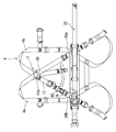
図1には、ハーネス型安全帯2(以下、安全帯2という)が示されている。図2は、図1の線分II−IIに沿った部分断面図が示されている。この安全帯2は、主ベルト4、尻当てベルト6、留め具としてのD環止め8、胸ベルト10、ガイドベルト12、スライド環14、延長ベルト15、一対の下連結環としての一対の連結環16、上連結環としてのD環17、墜落防止機器としての移動ロープ連結器18、一対の主バックル19、胸バックル20、結束バンド21及び胴ベルト22を備えている。図1は、背面から見た安全帯2が示されている。この図1の上下方向が安全帯2の上下方向であり、図1の左右方向が安全帯2の左右方向である。
FIG. 1 shows a harness type safety belt 2 (hereinafter referred to as a safety belt 2). FIG. 2 shows a partial cross-sectional view along the line segments II-II of FIG. The
主ベルト4は、一対のベルト体4a、4bを備えている。一方のベルト体4aは、長手方向一端部23aから他端部24aまで延在している。このベルト体4aは、安全帯2の左上方で折り返されている。折り返された一方は、左上から右下に向かって斜め下方に延在している。この斜め下方に向かって延在するベルト体4aは、安全帯2の中央上方で、他方のベルト体4bと交差している。
The
この安全帯2の中央上方での交差により、ベルト体4aとベルト体4bとは背交差部25を形成している。ベルト体4aは、背交差部25から更に斜め下方に延在して一端部23aに至っている。ベルト体4aは、一端部23aの近傍で他方のベルト体4bと交差している。この交差で側交差部26aが形成されている。図示されないが、この側交差部26aで、ベルト体4aとベルト体4bとは縫合されている。
Due to the intersection of the
安全帯2の左上方で折り返されたベルト体4aの他方は、下方に向かって延在している。この下方に向かって延在する他方は、安全帯2の上下方向において、中央より下方で、他方のベルト体4bと交差している。この交差により、側交差部26bが形成されている。図示されないが、この側交差部26bで、ベルト体4aとベルト体4bとは縫合されている。
The other side of the
ベルト体4aの他方は、側交差部26bから更に下方に延在して、安全帯2の左下方で折り返されている。折り返されたベルト体4aは、上方に向かって延在している。ベルト体4aの他端部24aは、他方のベルト体4bの一端部23bの近傍に位置している。ここでは、一方のベルト体4aについて説明がされたが、他方のベルト体4bは、一方のベルト体4aと左右対称に形成されている。このベルト体4aとベルト体4bとは、一対の肩ベルト28及び腿ベルト29を形成している。
The other side of the
この安全帯2では、ベルト体4aは左上方で折り返されて下方に向かって延在する部分と、側交差部26bから上方に向かって延在する部分との間で分割されて、この両者がベルト長さ調整具13を介して連結されている。このとき、ベルト体4bにおいても、ベルト体4aと同様に、ベルト体4bは右上方で折り返されて下方に向かって延在する部分と、側交差部26aから上方に向かって延在する部分とがベルト長さ調整具13によって、連結される。これにより、作業者Pの体型に合わせて、ベルト体4a及びベルト4bの長さ調整が可能にされている。
In this
尻当てベルト6は、安全帯2の上下方向下方で左右方向に延在している。尻当てベルト6の一端部は、ベルト体4aと重ねられて縫合されている。この縫合により、縫合部27aが形成されている。尻当てベルト6の他端部は、ベルト体4bと重ねられて縫合されている。この縫合により、縫合部27bが形成されている。
The buttock belt 6 extends in the left-right direction below the
D環止め8は、背交差部25の位置で、ベルト体4a及びベルト体4bに取り付けられている。D環止め8には、ベルト体4aとベルト体4bとが互いに交差して通されている。
The
胸ベルト10は、左ベルト30及び右ベルト32を備えている。左ベルト30の後端部は、ベルト体4aに取り付けられている。左ベルト30の後端部は、側交差部26bとベルト体4aの上方の折り返しとの間の位置で、ベルト体4aに縫合されている。右ベルト32の後端部は、ベルト体4bに取り付けられている。右ベルト32の後端部は、側交差部26aとベルト体4bの上方の折り返しとの間の位置で、ベルト体4bに縫合されている。
The
ガイドベルト12は、ベルト体4aに取り付けられている。ガイドベルト12は、ベルト体4aの背後に配置されている。ガイドベルト12の上端部12aは、背交差部25の位置で、D環17に連結されている。ガイドベルト12の下端部12bは、背交差部25と側交差部26aとの間で、ベルト体4aに連結されている。ガイドベルト12の下端部12bは、連結環16に連結されている。このガイドベルト12は、上端部12aから下端部12bまで、ベルト体4aに沿って延びている。
The
スライド環14は、ガイドベルト12に通されている。スライド環14は、ガイドベルト12に沿ってスライド可能にされている。
The
延長ベルト15の上端部15aは、スライド環14に連結されている。延長ベルト15の下端部15bは、移動ロープ連結器18に連結されている。これにより、スライド環14と移動ロープ連結器18とが連結されている。この移動ロープ連結器18は、スライド環14に直接に連結されていてもよい。図示されないが、延長ベルト15は、ショックアブソーバからなってもよい。ショックアブソーバは、その上端部から下端部まで延びるベルト本体と、その上端部から延びる一方の縫合用ベルトと下端部から延びる他方の縫合用ベルトとを備える。この上端部と下端部との間で、一方の縫合用ベルトと他方の縫合用ベルトとが縫合される。この縫合された一方の縫合用ベルトと他方の縫合用ベルトとがベルト本体と共に折り畳まれて樹脂製のカバーに収容される。
The
一方の連結環16は、背交差部25と側交差部26bとの間で、ベルト体4bに取り付けられている。この連結環16は、側交差部26bの近傍であって、側交差部26bの上方に配置されている。他方の連結環16は、一方の連結環16と同様に、背交差部25と側交差部26aとの間で、ベルト体4aに取り付けられている。
One connecting
D環17は、基部34及び湾曲部36を備えている。基部34は、略直線状に延びている。湾曲部36は基部34の一端部から他端部まで基部34から離れる向きに凸状に湾曲して延びている。この湾曲部36は滑らかな曲線で湾曲している。この湾曲部36は、円弧状にされてもよい。このD環17は、背交差部25で、D環止め8に取り付けられている。この基部34は、互いに交差するベルト体4a及びベルト体4bと、D環止め8とに挟まれて取り付けられている。
The
移動ロープ連結器18は、延長ベルト15の下端部に取り付けられている。移動ロープ連結器18は、胴ベルト22に仮固定されている。本発明では、通常の使用では固定された状態が維持され、人の体重が作用したときに固定が解除されるようにされていることを仮固定と称する。
The moving
それぞれの主バックル19は、ソケット38及びタングプレート40を備えている。このタングプレート40は、ソケット38に着脱可能にされている。一方の主バックル19では、ソケット38は、ベルト体4aの一端部23aに連結されている。タングプレート40は、ベルト体4bの他端部24bに連結されている。この主バックル19によって、ベルト体4aの一端部23aとベルト体4bの他端部24bとが連結及び連結解除可能にされている。同様に、他方の主バックル19によって、ベルト体4bの一端部23bとベルト体4aの他端部24aとが連結及び連結解除可能にされている。
Each
胸バックル20は、ソケット42及びタングプレート44を備えている。このタングプレート44は、ソケット42に着脱可能にされている。ソケット42は、第一ベルト30に連結されている。タングプレート44は、第二ベルト32に連結されている。この胸バックル20によって、第一ベルト30の先端部と第二ベルト32の先端部とが連結及び連結解除可能にされている。
The
一方の結束バンド21は、背交差部25と側交差部26bとの間で、ベルト体4bに取り付けられている。他方の結束バンド21は、背交差部25と側交差部26aとの間で、ベルト体4aに取り付けられている。この他方の結束バンド21は、ベルト体4aとガイドベルト12とを仮固定している。この安全帯2では、ベルト体4aとベルト体4bとに取り付けられた結束バンド21の数は1であるが、必ずしも必要ではなく、また結束バンド21の数は2以上であってもよい。
One of the binding
図示されないが、この他方の結束バンド21は、本体、一方の端部及び他方の端部を備えている。本体は、ベルト体4aに取り付けられている。一方の端部及び他方の端部は、ベルト体4aの長手方向に直交して互いに逆向きに延びている。この一対の端部は、ガイドベルト12の背後で重ね合わされている。一対の端部は、面ファスナーで着脱可能に接着している。この様にして、この結束バンド21は、ベルト体4aとガイドベルト12とを抱き込んで仮固定している。
Although not shown, the
胴ベルト22は、ベルト本体46、バックル48及び補助ベルト50を備えている。バックル48は、ベルト本体46の一端に取り付けられている。補助ベルト50は、ベルト本体46に取り付けられている。ベルト本体46と補助ベルト50は、側交差部26a及び側交差部26bの位置で、主ベルト4(4a、4b)に連結されている。バックス48にベルト本体46が通されて、胴ベルト22は人の腰骨周りに装着されうる。
The
この安全帯2は、一対の補強ベルト52を備えている。図2に示される様に、他方の補強ベルト52は、ベルト体4aに取り付けられている。この補強ベルト52は、本体部52a、一端部52b及び他端部52cを備えている。この本体部52aに他方の連結環16が連結されている。一端部52bは、ベルト体4aの長手方向一方に沿って延びている。一端部52bはベルト体4aに重ね合わされている。一端部52bとベルト体4aとが縫合されて第一縫合部54を形成している。他端部52cは、ベルト体4aの長手方向他方に沿って延びている。他端部52cはベルト体4aに重ね合わされている。他端部52cとベルト体4aとが縫合されて第二縫合部56を形成している。この補強ベルト52によって、連結環16は、ベルト体4aに取り付けられている。一方の連結環16は、同様にして、補強ベルト52によって、ベルト体4bに取り付けられている。
The
ガイドベルト12は、ガイドベルト本体58及びフック60を備えている。ガイドベルト本体58の上端部58aは、D環17の湾曲部36に連結されている。上端部58aは、湾曲部36に沿ってスライド可能にされている。ガイドベルト本体58の下端部58bに、フック60が連結されている。ガイドベルト12の下端部としてのフック60は、鉤型形状のフック本体60aと、フック本体60aの開口を開閉する外れ止め60bとを備えている。このフック60は連結環16に連結されている。
The
この安全帯2は、補強ガイドベルト62を備えている。補強ガイドベルト62は、ガイドベルト本体58とベルト体4aとの間で、ガイドベルト本体58に沿って延びている。補強ガイドベルト62の上端部62aは、ガイドベルト本体58の上端部58aに縫合されている。補強ガイドベルト62の下端部62bは、ガイドベルト本体58の下端部58bに縫合されている。
The
結束バンド21は、本体21a、端部21b及び端部21cを備えている。本体21aは、ベルト体4aに取り付けられている。端部21bは本体21aからベルト体4aの長手方向に直交する一方の向きに延びている。端部21cは本体21aからベルト体4aの長手方向に直交する他方の向きに延びている。この端部21b及び端部21cは、本体21aとの間に、ガイドベルト本体58及び補強ガイドベルト62を挟み込む。ガイドベルト本体58及び補強ガイドベルト62を挟み込んだ状態で、端部21bと端部21cとが重ね合わされる。この重ね合わされた端部21bと端部21cとが面ファスナーで接着される。この接着は、解除可能にされている。この様にして、このガイドベルト12及び補強ガイドベルト62は、ベルト体4aに仮固定されている。
The binding
図1の点Gは、上下方向において、安全帯2を装着した人の重心位置を表している。図2の点Sは、スライド環14のスライド下端を表している。このスライド下端Sは、ガイドベルト12とベルト体4a(4b)との間でスライドするスライド部14aの下降端として特定される。この安全帯2では、フック本体60aの上端によって、スライド環14のスライド下端Sが定められている。点Pは、側交差部26aの中心位置を表している。図2の片矢印Lは、側交差部26aの中心位置Pからスライド下端Sまでの長さを表している。この長さLは、ベルト体4bの長手方向に沿って測られる。この安全帯2では、補強ベルト52の本体部52aと、連結環16と、フック本体60aと、ガイドベルト12とが、ベルト体4a(4b)の長手方向に張られて、ベルト体4a(4b)に沿って重ね合わされた状態で、この長さLは測定される。ガイドベルト12は、スライド環14のスライド下端Sが重心Gより上方に位置するようにされている。
The point G in FIG. 1 represents the position of the center of gravity of the person wearing the
図3には、移動ロープ連結器18が示されている。この移動ロープ連結器18は、連結器本体64と、取付基部66と、延長ベルト連結環としての連結環68と、内バンド70と、外バンド72とを備えている。
FIG. 3 shows the moving
連結器本体64は、一対の連結部74を備えている。それぞれの連結部74には、命綱としての移動ロープRの連結金具76が連結される。移動ロープRは、作業がされる範囲に間隔を空けて設置されている。この移動ロープRの後端は建造物などに連結されている。移動の際に、移動方向の移動ロープRの連結金具76が連結器本体64の一方の連結部74に連結する。一方の連結部74に連結金具76が連結された後に、他方の連結部74の連結金具76の連結が解除される。この連結器本体64は、常に、作業中において、少なくとも1本の移動ロープRが連結された状態を維持する。この移動ロープ連結器18を使用することで、命綱に連結されていない状態での移動が防止される。
The
この連結器本体64は、取付基部66の表面66a側に取り付けられている。取付基部66の上端部に連結環68が連結されている。連結環68は、ベルト通し孔68aを備えている。連結環68は、ベルト通し孔68aの軸線に平行な方向を回動軸として回動可能にされている。
The
内バンド70は、本体70a、端部70b及び端部70cを備えている。本体70aは、取付基部66に取り付けられている。端部70bは本体70aの上端から延びている。端部70cは、本体70aの下端から延びている。端部70bと端部70cとは取付基部66の裏面側で重ね合わせ可能にされている。この重ね合わされた端部70bと端部70cとが面ファスナーで接着及び接着解除可能にされる。外バンド72は、内バンド70と同様に、その本体が取付基部66に取り付けられている。外バンド72の端部72bと端部72cとは取付基部66の裏面側で重ね合わせ可能にされている。この重ね合わされた端部72bと端部72cとが面ファスナーで接着及び接着解除可能にされる。
The
図1に示される様に、この連結環68のベルト通し孔68aに、延長ベルト15の下端部15bが通されている。これにより、移動ロープ連結器18は、延長ベルト15に連結されている。内バンド70は、その本体70aと端部70b及び70cとの間に胴ベルト22を挟み込んでいる。端部70bと端部70cとが重ね合わされて、面ファスナーで接着されている。この内バンド70は、移動ロープ連結器18を胴ベルト22に仮固定している。更に外バンド72も、内バンド70と同様にして、移動ロープ連結器18を胴ベルト22に仮固定している。この連結環68は、安全帯2を装着する人の右腰に位置する。
As shown in FIG. 1, the
図4では、フック60は、ベルト体4bに取り付けられている左側の連結環16に連結されている。ガイドベルト12の上端部12aは、D環17の湾曲部36の左側に位置している。図示されないが、このとき、移動ロープ連結器18は、左側の側交差部26bの近傍に位置している。この位置で、移動ロープ連結器18は、胴ベルト22に仮固定している。この図1と図4と示される様に、この安全帯2では、ガイドベルト12がベルト体4aとベルト体4bとのいずれにも取り付けられうる。
In FIG. 4, the
図5(a)には、この安全帯2を装着した作業者Pが示されている。この移動ロープ連結器18は、作業者Pの左側に仮固定されている。このとき、図4に示される様に、フック60は、ベルト体4bに取り付けられている左側の連結環16に連結されている。一対の肩ベルト28は、作業者Pの腕が通されて、肩に掛けられている。一対の腿ベルト29は、作業者Pの足が通されて、腿周りに掛けられている。移動ロープ連結器18に移動ロープRが連結されている。移動ロープRが連結された状態で、作業者Pは移動しうる。作業者Pは、移動ロープ連結器18に連結される移動ロープRを代えながら移動しうる。
FIG. 5A shows an operator P wearing the
図5(b)には、作業者Pが水平な姿勢で落下する様子が示されている。図5(b)の矢印Fpは、作業者の体の移動向きを表している。矢印Fbは、延長ベルト15の移動向きを表している。矢印Fpの向きに落下する作業者Pの体重で腿ベルト29から連結器本体64が外れている。延長ベルト15は、スライド環14と共に、回動している。図5(b)において、作業者の重心Gは、スライド環14より足側に位置している。
FIG. 5B shows a state in which the worker P falls in a horizontal posture. The arrow Fp in FIG. 5B indicates the moving direction of the worker's body. The arrow Fb indicates the moving direction of the
図6(a)では、重心Gが位置する足側が下方になる向きに、作業者Pの身体が回動する。このとき、スライド環14は、ガイドベルト12に沿って頭部側にスライドする。スライド環14は、結束バンド21の仮固定を解除して(図1及び図2参照)、頭部側に更にスライドする。作業者Pの姿勢は、図6(a)から図6(b)に移行する。
In FIG. 6A, the body of the worker P rotates in a direction in which the foot side where the center of gravity G is located is downward. At this time, the
図6(b)では、作業者Pの重心Gが、フック17の略真下に来た状態を表している。図6(b)の位置で、スライド環14のスライドが停止する。作業者Pの姿勢は、立ち姿勢に近い姿勢になっている。これにより、救助されるまでの間、吊り下げられた作業者は受ける負担を軽減される。
FIG. 6B shows a state in which the center of gravity G of the worker P is substantially directly below the
この安全帯2では、一対の連結環16を備えているので、移動ロープ連結器18は、左右いずれの位置にも仮固定できる。この移動ロープ連結器18は、作業の邪魔にならない様に、左右いずれかに取り付けられる。この安全帯2は、移動ロープRが左右いずれの方向から延びていても、操作性を損なわない。移動ロープ連結器18は、左右の取付位置を容易に変更できる。移動ロープ連結器18の取付位置が左右異なる2つの安全帯を準備する必要がない。
Since the
この安全帯2では、ガイドベルト12の上端部12aは、背交差部25の位置で連結されている。このガイドベルト12は、左右いずれの連結環16にも、同じ長さで弛み無く連結できる。ガイドベルト12は、ベルト体4a及びベルト体4bのいずれにも沿って延在しうる。この安全帯2では、緩んだガイドベルト12が構造物等に引っかかることが抑制される。又、ガイドベルト12の左右付け替えに伴って、ガイドベルト12の長さ調節をする手間が掛からない。
In the
ガイドベルト12の上端部12aは、D環17の湾曲部36に沿って左右にスライド可能にされている。このガイドベルト12は、左右いずれの連結環16にも、捩れることなく連結しうる。このガイドベルト12は、左右いずれの連結環16に連結しても、スライド環14がスムーズにスライドしうる。
The
この安全帯2では、フック60でガイドベルト12が連結環16に連結される。このガイドベルト12は、左右の連結環16への付け替えが容易にされている。更に、このフック60は、外れ止め60bを備えているので、連結環16とフック60との連結が意図せずに解除されることが防止されている。
In the
この安全帯2では、スライド環14のスライド下端Sは、作業者Pの重心Gより上方の頭部側に位置している。これにより、落下するときの作業者の姿勢に関わらず、作業者Pの墜落を阻止するときの姿勢は、常に立ち姿勢に近い姿勢になる。この安全帯2は、吊り下げられた作業者Pの負担を軽減しうる。
In the
この胴ベルト22は、作業者Pの腰骨の位置に装着される。ここでいう腰骨は、腸骨で前方にとがった部分である上前腸骨棘を指す。作業者Pの高さ方向において、この上前腸骨棘の位置は、一般に身長の54.5%の高さにある。一方、重心Gの位置は、一般に身長の55%の高さにある。この胴ベルト22は、作業者Pの重心Gより僅かに低い位置で、作業者Pに装着される。このベルト本体78の高さは、側交差部77bの高さと略等しい。この安全帯2では、作業者Pの姿勢を確実に立ち姿勢に近い姿勢にする観点から、側交差部26bの中心位置Pからスライド下端Sまでの長さLは、好ましくは10cm以上であり、更に好ましくは15cm以上である。
The
この安全帯2では、延長ベルト15を備えているので、スライド環14が重心Gより上方に位置しながら、移動ロープ連結器18は、重心Gより下方に位置しうる。これにより、移動ロープ連結器18の目視確認が容易にできる。また、移動ロープ連結器18の操作が容易にされている。この操作性の観点から、この安全帯2では、移動ロープ連結器18は重心G又は重心Gより下方に位置させることが好ましい。この安全帯2は、吊り下げられた作業者の負担を軽減すると共に、操作性に優れている。
Since the
この安全帯2では、移動ロープ連結器18は、胴ベルト22に仮固定されたが、これに限られない。この移動ロープ連結器18は操作し易い位置にあればよい。この移動ロープ連結器18は、例えば、肩ベルト28又は腿ベルト29に仮固定されてもよい。この移動ロープ連結器18は、作業中において作業者Pが操作し易い様に、作業者の重心G又は重心Gより低い位置にあることが好ましい。
In this
この安全帯2では、補強ガイドベルト62がガイドベルト12に沿って延びている。ガイドベルト12及び補強ガイドベルト62がスライド環14に通される。スライド環14は、補強ガイドベルト62に接触してスライドする。この補強ガイドベルト62は、スライド環14のスライドからガイドベルト12を保護する。この安全帯64は、安全性に優れている。
In the
この安全帯2では、連結環16は、補強ベルト52によって、主ベルト4に連結されている。この補強ベルト52と主ベルト4とは、第一縫合部54及び第二縫合部56を形成している。作業者Pが墜落を阻止されるときに、スライド環14のスライドによってガイドベルト12に大きな力が作用する。このスライド環14によって、補強ベルト52をベルト体4bから剥がす向きの力が補強ベルト52に作用することがある。このとき、第一縫合部54及び第二縫合部56は、補強ベルト52が主ベルト4から離れる向きにずれることを阻止する。この補強ベルト52を備えることで、ガイドベルト12は主ベルト4に強固に固定されている。この安全帯2は、安全性に優れている。
In the
この安全帯2では、仮固定に面ファスナーを用いているので、移動ロープ連結器18の仮固定が容易にされている。しかし、この仮固定は、これに限られない。この仮固定は、通常の使用では固定された状態が維持され、人体に墜落阻止時に加わる力が作用したときに固定が解除されるものであればよい。
In this
この安全帯2は、延長ベルト15としてショックアブソーバを備えていてもよい。墜落阻止の大きな衝撃荷重が作用したときに、ショックアブソーバは、この衝撃荷重を緩和する。ショックアブソーバは、作業者Pが墜落を阻止される際に受ける衝撃を緩和する。更に、ショックアブソーバは、ガイドベルト12に作用する衝撃を緩和する。ショックアブソーバを備える安全帯2は、更に安全性に優れている。
The
この安全帯2では、移動ロープ連結器18からスライド環14までの長さは、移動ロープ連結器18からD環17までの長さに比べて短い。この安全帯2では、このスライド環14が、スライド下端SからD環17の近傍までスライドする。D環17と移動ロープ連結器18とを延長ベルトで連結した安全帯に比べて、安全帯2では落下距離が短い。この安全帯2は、墜落阻止時に吊り下げられた作業者Pが常に立ち姿勢に近い姿勢になるとともに、落下距離も短くできる。
In this
更に、ガイドベルト12とベルト体4bとは、結束バンド21によって仮固定されている。これにより、通常の使用時には、結束バンド21は、スライド環14の上方へのずれ止めとして機能する。この安全帯2では、移動ロープ連結器18が固定されていなくても、通常の使用時に移動ロープ連結器18が上方にずれ上がることが抑制されている。
Further, the
図7には、他の実施形態に係る安全帯82(以下、安全帯82という)の一部が示されている。この安全帯82は、安全帯2の移動ロープ連結器18に代えて、巻取器84を備えている。更に、安全帯82はフック90を備えている。この安全帯82は、巻取器84及びフック90以外の構成は、安全帯2と同様にされている。ここでは、安全帯82について、安全帯2と異なる構成について説明がされ、安全帯2と同様の構成の説明が省略される。また、安全帯2と同様の構成については、同様の符号が使用される。
FIG. 7 shows a part of the safety belt 82 (hereinafter referred to as the safety belt 82) according to another embodiment. The
この巻取器84は、巻取器本体86と巻取器本体86に収容されるストラップ88とを備えている。このストラップ88は、巻取器本体86から繰り出されうる。ストラップ88は捲き取られて巻取器本体86に収容されうる。このストラップ88にフック90が連結されている。この巻取器本体86は、胴ベルト22に仮固定される。この巻取器本体86は、肩ベルト28又は腿ベルト29に仮固定されてもよい。この安全帯82では、フック90が建造物等に係止される。
The
この巻取器84や前述の移動ロープ連結器18は墜落防止機器としての例示であって、使用される墜落防止機器はこれらに限られない。本発明の墜落防止機器は、作業者Pを命綱に連結して墜落事故を防止する機器であればよい。
The
図示されないが、例えば、この延長ベルト15の下端部15bに、ランヤードが連結されていてもよい。ランヤードは、フック、ロープ及び連結フックを備えている。フックは、鉤型形状のフック本体と、フック本体の開口を開閉する外れ止めとを備えている。このフック本体はロープの先端部に連結されている。連結フックは、ロープの後端部に連結されている。連結フックは、着脱可能に、延長ベルト15の下端部15bに連結される。また、このランヤードの連結フックは、スライド環14に連結されてもよい。
Although not shown, for example, a lanyard may be connected to the
以上説明された本発明は、ハーネス型安全帯に広く適用されうる。 The present invention described above can be widely applied to a harness type safety belt.
2、82・・・ハーネス型安全帯
4・・・主ベルト
4a、4b・・・ベルト体
6・・・尻当てベルト
8・・・D環止め
10・・・胸ベルト
12・・・ガイドベルト
14・・・スライド環
15・・・延長ベルト
16・・・連結環
17・・・D環
18・・・移動ロープ連結器
19・・・主バックル
20・・・胸バックル
21・・・結束バンド
22・・・胴ベルト
25・・・背交差部
26a、26b・・・側交差部
28・・・肩ベルト
29・・・腿ベルト
36・・・湾曲部
52・・・補強ベルト
54・・・第一縫合部
56・・・第二縫合部
60・・・フック
60a・・・フック本体
60b・・・外れ止め
62・・・補強ガイドベルト
84・・・巻取器
2, 82 ... Harness
Claims (13)
ガイドベルトと、上記ガイドベルトに沿ってスライドするスライド環と、上記ガイドベルトの下端部を着脱可能に連結する一対の下連結環と、上記スライド環に連結されている墜落防止機器とを備えており、
上記主ベルトが一対のベルト体を備えており、この一対のベルト体が装着する人の背中で交差して背交差部を形成しており、
上記ガイドベルトが上記主ベルトの背後に配置されており、
上記ガイドベルトの上端部が上記背交差部又は上記背交差部より上方で上記主ベルトに連結されており、
上記一対の下連結環の一方が上記背交差部の下方の位置で上記一対のベルト体の一方に連結されており、上記一対の下連結環の他方が上記背交差部の下方の位置で上記一対のベルト体の他方に連結されているハーネス型安全帯。 A harness-type safety belt provided with a main belt forming a pair of shoulder belts and a pair of thigh belts.
A guide belt, a slide ring that slides along the guide belt, a pair of lower connecting rings that detachably connect the lower end of the guide belt, and a fall prevention device connected to the slide ring are provided. Ori,
The main belt includes a pair of belt bodies, and the pair of belt bodies intersect with each other on the back of the wearer to form a back intersection.
The guide belt is placed behind the main belt,
The upper end of the guide belt is connected to the main belt above the back intersection or the back intersection.
One of the pair of lower connecting rings is connected to one of the pair of belt bodies at a position below the back intersection, and the other of the pair of lower connecting rings is connected to one of the pair of belt bodies at a position below the back intersection. A harness-type safety belt connected to the other of the pair of belt bodies.
上記上連結環が基部と湾曲部とを備えており、
上記湾曲部が上記基部の両端の間で上記基部から離れる向きに凸状に湾曲して延びており、
上記基部が上記背交差部に連結されており、
上記ガイドベルトの上端部が上記湾曲部に連結されて上記湾曲部に沿ってスライド可能にされている請求項1に記載のハーネス型安全帯。 The upper connecting ring is provided with an upper connecting ring to which the upper end portion of the guide belt is connected, and the upper connecting ring is provided with a base portion and a curved portion.
The curved portion extends so as to be convexly curved in a direction away from the base portion between both ends of the base portion.
The base is connected to the back intersection,
The harness-type safety belt according to claim 1, wherein the upper end portion of the guide belt is connected to the curved portion and slidable along the curved portion.
上記フック本体が上記下連結環に着脱可能に連結されている請求項1又は2に記載のハーネス型安全帯。 The lower end of the guide belt is equipped with a hook-shaped hook body and a stopper that opens and closes the opening of the hook body.
The harness-type safety belt according to claim 1 or 2, wherein the hook body is detachably connected to the lower connecting ring.
上記スライド環のスライド下端が上記背交差部より下方であって装着する人の重心より上方に位置しており、
上記墜落防止機器が上記延長ベルトの下端部に連結されており、装着する人の重心又は重心より下方に位置している請求項1から3のいずれかに記載のハーネス型安全帯。 It is equipped with an extension belt with the upper end connected to the slide ring.
The lower end of the slide of the slide ring is located below the back intersection and above the center of gravity of the wearer.
The harness-type safety belt according to any one of claims 1 to 3, wherein the fall prevention device is connected to the lower end of the extension belt and is located at the center of gravity of the wearer or below the center of gravity.
上記補強ガイドベルトが上記ガイドベルトと上記主ベルトとの間で上記ガイドベルトに沿って延びており、
上記スライド環に上記ガイドベルトと上記補強ガイドベルトとが通されている請求項1から5のいずれかに記載のハーネス型安全帯。 Equipped with a reinforced guide belt
The reinforcing guide belt extends along the guide belt between the guide belt and the main belt.
The harness-type safety belt according to any one of claims 1 to 5, wherein the guide belt and the reinforcing guide belt are passed through the slide ring.
上記墜落防止機器が上記胴ベルトに仮固定されている請求項1から6のいずれかに記載のハーネス型安全帯。 Equipped with a torso belt that can be wrapped around the wearer's waist
The harness-type safety belt according to any one of claims 1 to 6, wherein the fall prevention device is temporarily fixed to the body belt.
Priority Applications (1)
| Application Number | Priority Date | Filing Date | Title |
|---|---|---|---|
| JP2017124050A JP6864355B2 (en) | 2017-06-26 | 2017-06-26 | Harness type safety belt |
Applications Claiming Priority (1)
| Application Number | Priority Date | Filing Date | Title |
|---|---|---|---|
| JP2017124050A JP6864355B2 (en) | 2017-06-26 | 2017-06-26 | Harness type safety belt |
Publications (2)
| Publication Number | Publication Date |
|---|---|
| JP2019005263A JP2019005263A (en) | 2019-01-17 |
| JP6864355B2 true JP6864355B2 (en) | 2021-04-28 |
Family
ID=65026133
Family Applications (1)
| Application Number | Title | Priority Date | Filing Date |
|---|---|---|---|
| JP2017124050A Active JP6864355B2 (en) | 2017-06-26 | 2017-06-26 | Harness type safety belt |
Country Status (1)
| Country | Link |
|---|---|
| JP (1) | JP6864355B2 (en) |
Families Citing this family (1)
| Publication number | Priority date | Publication date | Assignee | Title |
|---|---|---|---|---|
| CN112933457B (en) * | 2021-04-09 | 2021-12-14 | 中铁十七局集团建筑工程有限公司 | Anti-fall safety belt tie-down device for mobile operation and anti-fall method |
Family Cites Families (4)
| Publication number | Priority date | Publication date | Assignee | Title |
|---|---|---|---|---|
| JPH08182770A (en) * | 1994-12-29 | 1996-07-16 | Polymer Giya Kk | Safety band for height place work |
| JP2005000282A (en) * | 2003-06-10 | 2005-01-06 | Fujii Denko Co Ltd | Harness type safety belt |
| JP2009005765A (en) * | 2007-06-26 | 2009-01-15 | Fujii Denko Co Ltd | Full harness type safety belt |
| JP6494993B2 (en) * | 2014-12-11 | 2019-04-03 | 藤井電工株式会社 | Parallel 2-roll lanyard for safety belts and connecting fittings used therefor |
-
2017
- 2017-06-26 JP JP2017124050A patent/JP6864355B2/en active Active
Also Published As
| Publication number | Publication date |
|---|---|
| JP2019005263A (en) | 2019-01-17 |
Similar Documents
| Publication | Publication Date | Title |
|---|---|---|
| EP3863732B1 (en) | Harness with adjustable belt strap | |
| JP5456798B2 (en) | Safety harness | |
| US2699284A (en) | Safety harness | |
| USRE35028E (en) | Safety harness with adjustable front D-ring | |
| KR20160134543A (en) | Improved roping harness | |
| EP0744192A2 (en) | Fall protection safety suit | |
| US9168401B2 (en) | Convertible suspension / seat harness | |
| EP3678745A1 (en) | Harness with pivoting hip connection | |
| US20150060195A1 (en) | Harness with Integral Relief Loops for Suspension Trauma | |
| JP2019039098A (en) | Work uniform with safety belt | |
| JP7199130B1 (en) | fall arrest equipment | |
| US9492692B2 (en) | Attachable arrangement | |
| JP6923197B2 (en) | Harness type safety belt chest belt mounting structure | |
| JP6864355B2 (en) | Harness type safety belt | |
| KR102034375B1 (en) | Multi-purpose working clothes forming in a body with harness | |
| JP2004141480A (en) | Harness-like safety belt | |
| US20250135246A1 (en) | Safety harness | |
| JP6733884B2 (en) | Harness type safety belt | |
| JP6898635B2 (en) | Harness type safety belt | |
| EP3034133B1 (en) | Safety harness with vertically adjustable belt | |
| DK2589414T3 (en) | survival suit | |
| JP2011024838A (en) | Hip hanging belt of pole safety belt | |
| JP6796873B2 (en) | Harness and life jacket | |
| JP2024022991A (en) | Harness-integrated assist suit | |
| EP4442329A1 (en) | Harness leg loop |
Legal Events
| Date | Code | Title | Description |
|---|---|---|---|
| A80 | Written request to apply exceptions to lack of novelty of invention |
Free format text: JAPANESE INTERMEDIATE CODE: A80 Effective date: 20170628 |
|
| A621 | Written request for application examination |
Free format text: JAPANESE INTERMEDIATE CODE: A621 Effective date: 20200420 |
|
| RD02 | Notification of acceptance of power of attorney |
Free format text: JAPANESE INTERMEDIATE CODE: A7422 Effective date: 20200420 |
|
| A977 | Report on retrieval |
Free format text: JAPANESE INTERMEDIATE CODE: A971007 Effective date: 20210310 |
|
| TRDD | Decision of grant or rejection written | ||
| A01 | Written decision to grant a patent or to grant a registration (utility model) |
Free format text: JAPANESE INTERMEDIATE CODE: A01 Effective date: 20210323 |
|
| A61 | First payment of annual fees (during grant procedure) |
Free format text: JAPANESE INTERMEDIATE CODE: A61 Effective date: 20210326 |
|
| R150 | Certificate of patent or registration of utility model |
Ref document number: 6864355 Country of ref document: JP Free format text: JAPANESE INTERMEDIATE CODE: R150 |
|
| R250 | Receipt of annual fees |
Free format text: JAPANESE INTERMEDIATE CODE: R250 |
|
| R250 | Receipt of annual fees |
Free format text: JAPANESE INTERMEDIATE CODE: R250 |