JP6875018B2 - Orthodontics - Google Patents
Orthodontics Download PDFInfo
- Publication number
- JP6875018B2 JP6875018B2 JP2019141471A JP2019141471A JP6875018B2 JP 6875018 B2 JP6875018 B2 JP 6875018B2 JP 2019141471 A JP2019141471 A JP 2019141471A JP 2019141471 A JP2019141471 A JP 2019141471A JP 6875018 B2 JP6875018 B2 JP 6875018B2
- Authority
- JP
- Japan
- Prior art keywords
- dentition
- peripheral wall
- base portion
- inner peripheral
- outer peripheral
- Prior art date
- Legal status (The legal status is an assumption and is not a legal conclusion. Google has not performed a legal analysis and makes no representation as to the accuracy of the status listed.)
- Active
Links
Images


Classifications
-
- A—HUMAN NECESSITIES
- A61—MEDICAL OR VETERINARY SCIENCE; HYGIENE
- A61C—DENTISTRY; APPARATUS OR METHODS FOR ORAL OR DENTAL HYGIENE
- A61C7/00—Orthodontics, i.e. obtaining or maintaining the desired position of teeth, e.g. by straightening, evening, regulating, separating, or by correcting malocclusions
- A61C7/08—Mouthpiece-type retainers or positioners, e.g. for both the lower and upper arch
-
- A—HUMAN NECESSITIES
- A61—MEDICAL OR VETERINARY SCIENCE; HYGIENE
- A61C—DENTISTRY; APPARATUS OR METHODS FOR ORAL OR DENTAL HYGIENE
- A61C7/00—Orthodontics, i.e. obtaining or maintaining the desired position of teeth, e.g. by straightening, evening, regulating, separating, or by correcting malocclusions
- A61C7/36—Devices acting between upper and lower teeth
Landscapes
- Health & Medical Sciences (AREA)
- Oral & Maxillofacial Surgery (AREA)
- Dentistry (AREA)
- Epidemiology (AREA)
- Life Sciences & Earth Sciences (AREA)
- Animal Behavior & Ethology (AREA)
- General Health & Medical Sciences (AREA)
- Public Health (AREA)
- Veterinary Medicine (AREA)
- Dental Tools And Instruments Or Auxiliary Dental Instruments (AREA)
- Orthopedics, Nursing, And Contraception (AREA)
Description
本発明は、例えば乳歯列から永久歯列に生え変わる小児に用いられる歯科矯正具に関する。 The present invention relates to, for example, an orthodontic appliance used for a child who changes from a deciduous dentition to a permanent dentition.
従来、歯列を矯正する器具には、例えば歯列に装着するマウスピースがある。このようなマウスピースは、上歯全体又は下歯全体を覆う形状に形成されている。すなわち、上記マウスピースは、口腔内に挿入し、使用者の該当する歯列弓(アーチ)上に装着したとき、そのアーチに歯係合部材が矯正力を与えるように、オープンフレーム構造を有している(例えば、特許文献1参照)。 Conventionally, an orthodontic appliance includes, for example, a mouthpiece attached to the dentition. Such a mouthpiece is formed in a shape that covers the entire upper tooth or the entire lower tooth. That is, the mouthpiece has an open frame structure so that when the mouthpiece is inserted into the oral cavity and mounted on the user's corresponding dental arch, the tooth engaging member gives an orthodontic force to the arch. (See, for example, Patent Document 1).
しかしながら、上述した特許文献1に記載された従来のマウスピースでは、前歯の歯列を比較的長い期間を要せずに矯正することができるものの、歯列を横方向に拡げる力が弱いため、奥歯の歯列を矯正するのに長い期間を要するという問題がある。 However, with the conventional mouthpiece described in Patent Document 1 described above, although the dentition of the anterior teeth can be corrected without requiring a relatively long period of time, the force for expanding the dentition in the lateral direction is weak. There is a problem that it takes a long time to correct the dentition of the back teeth.
また、歯列が叢生状態であると、舌や口腔周囲筋が調和のとれた場所に位置することができない場合がある。このように口腔周囲の筋肉の不調和は、不正咬合の原因になることがある。 In addition, when the dentition is crowded, the tongue and perioral muscles may not be able to be located in a harmonious place. Thus, the muscle discord around the oral cavity can cause malocclusion.
本発明はこのような問題に鑑みてなされたものであり、歯列を横方向に拡げるとともに、歯列を矯正し、口腔周辺の筋機能を整えることが可能な歯科矯正具を提供することを課題としている。 The present invention has been made in view of such a problem, and provides an orthodontic appliance capable of laterally expanding the dentition, correcting the dentition, and adjusting the muscle function around the oral cavity. It is an issue.
かかる課題を達成するために、請求項1に記載の発明は、上顎の上歯列及び下顎の下歯列に挟まれ、平面視U字状に形成されたベース部と、前記ベース部の外周縁側に設けられ、上下方向に突出する外周壁と、前記ベース部の内周縁側に設けられ、上下方向に突出し平面視コ字状に形成された内周壁と、を備え、前記内周壁のコ字状の両角部は、左右の前歯と左右の奥歯との間に対応する位置にそれぞれ形成され、前記内周壁は、前記ベース部よりも上方に設けられた上部壁と、前記ベース部よりも下方に設けられた下部壁とを備え、前記上部壁は、前記コ字状の両角部の間に形成された前側上部側面部と、前記コ字状の両角部の前記左右の奥歯側にそれぞれ形成された左右上部側面部とを有し、前記下部壁は、前記コ字状の両角部の間に形成された前側下部側面部と、前記コ字状の両角部の前記左右の奥歯側にそれぞれ形成された左右下部側面部とを有し、前記前側上部側面部は、前記上歯列の前記前歯が当接可能であって、上辺から前記ベース部に接する下辺にいくに従って前記外周壁との間隔が狭くなるような前側上部傾斜面が形成され、前記前側下部側面部は、前記下歯列の前記前歯が当接可能であって、下辺から前記ベース部に接する上辺にいくに従って前記外周壁との間隔が狭くなるような前側下部傾斜面が形成され、前記左右上部側面部は、前記上歯列の前記奥歯が当接可能であって、上辺から前記ベース部に接する下辺にいくに従って前記外周壁との間隔が狭くなるような左右上部傾斜面が形成され、前記左右下部側面部は、前記下歯列の前記奥歯が当接可能であって、下辺から前記ベース部に接する上辺にいくに従って前記外周壁との間隔が狭くなるような左右下部傾斜面が形成され、前記前側上部傾斜面は、前記左右上部傾斜面よりも傾斜角度が緩やかになるように形成され、前記前側下部傾斜面は、前記左右下部傾斜面よりも傾斜角度が緩やかになるように形成されている歯科矯正具としたことを特徴とする。 In order to achieve such a problem, the invention according to claim 1 has a base portion sandwiched between the upper dentition of the upper jaw and the lower dentition of the lower jaw and formed in a U shape in a plan view, and an outer circumference of the base portion. The inner peripheral wall is provided with an outer peripheral wall provided on the edge side and projecting in the vertical direction, and an inner peripheral wall provided on the inner peripheral edge side of the base portion and protruding in the vertical direction and formed in a U-shape in a plan view. Both U-shaped corners are formed at corresponding positions between the left and right front teeth and the left and right back teeth, and the inner peripheral wall is formed from the upper wall provided above the base portion and the base portion. Also provided with a lower wall provided below, the upper wall is located on the front upper side surface formed between the U-shaped corners and on the left and right molar sides of the U-shaped corners. Each has left and right upper side surface portions, and the lower wall has a front lower side surface portion formed between the U-shaped corner portions and the left and right back tooth sides of the U-shaped corner portions. Each of the left and right lower side surface portions is formed on the above side surface, and the front side upper side surface portion is capable of contacting the front teeth of the upper dentition, and the outer peripheral wall as it goes from the upper side to the lower side in contact with the base portion. is interval is front upper inclined surface such that narrower and the front lower side part, the according to the front teeth of the lower tooth row is a possible contact, go to the upper side in contact with the lower side to the base portion A front lower lower inclined surface is formed so that the distance from the outer peripheral wall is narrowed, and the left and right upper side surface portions are accessible to the back teeth of the upper dentition and go from the upper side to the lower side in contact with the base portion. the distance between the outer wall are formed left and right upper inclined surface such that a narrow, the right and left lower side surface portion is the back teeth of the lower dentition was possible abutment, upper in contact with the base portion from the lower side in accordance with The left and right lower inclined surfaces are formed so that the distance from the outer peripheral wall becomes narrower, and the front upper inclined surface is formed so that the inclination angle is gentler than the left and right upper inclined surfaces, and the front lower portion is formed. The inclined surface is characterized by being an orthodontic tool formed so that the inclination angle is gentler than that of the left and right lower inclined surfaces.
また、請求項2に記載の発明は、請求項1に記載の構成に加え、左右の第一大臼歯に対応する前記左右上部傾斜面及び前記左右下部傾斜面の左右の最下部の間隔が少なくとも36mmとしたことを特徴とする。
Further, in the invention according to
また、請求項3に記載の発明は、請求項1又は2に記載の構成に加え、前記ベース部、前記外周壁、及び前記内周壁は、弾性を有する樹脂材料で一体成形されていることを特徴とする。
Further, in the invention according to claim 3 , in addition to the configuration according to
請求項1に記載の発明によれば、内周壁が平面視コ字状に形成され、このコ字状の両角部が左右の前歯と左右の奥歯との間に対応する位置にそれぞれ形成され、前側上部傾斜面が左右上部傾斜面よりも傾斜角度が緩やかになるように形成され、前側下部傾斜面が左右下部傾斜面よりも傾斜角度が緩やかになるように形成されているので、例えば乳歯列から永久歯列に生え変わるときに、上歯列が前側上部傾斜面及び左右上部傾斜面に当接する一方、下歯列が前側下部傾斜面及び左右下部傾斜面に当接することで、歯列を横方向に広げるとともに、歯列を矯正し、口腔周辺の筋機能を整えることが可能となる。
また、請求項1に記載の発明によれば、内周壁は、平面視コ字状に形成されているので、舌を正しい位置に拘束することができ、口腔周辺の筋機能を一段と整えることが可能となる。
さらに、請求項1に記載の発明によれば、内周壁のコ字状の両角部は、左右の前歯と左右の奥歯との間に対応する位置にそれぞれ形成されているので、歯科矯正具を上歯列及び下歯列の生え方の特性に確実に適合させることができる。その結果、歯科矯正具の着用感を向上させるとともに、永久歯列の拡大効果及び矯正効果を一段と高めることが可能となる。
According to the invention of claim 1, the inner peripheral wall is formed in a U-shape in a plan view, and both corners of the U-shape are formed at positions corresponding to the left and right front teeth and the left and right back teeth, respectively. The front upper inclined surface is formed so that the inclined angle is gentler than the left and right upper inclined surfaces, and the front lower inclined surface is formed so that the inclined angle is gentler than the left and right lower inclined surfaces. The upper dentition abuts on the anterior upper sloping surface and the left and right upper sloping surfaces , while the lower dentition abuts on the anterior lower sloping surface and the left and right lower sloping surfaces to lateralize the dentition. It is possible to expand in the direction, correct the dentition, and adjust the muscle function around the oral cavity.
Further, according to the invention of claim 1, since the inner peripheral wall is formed in a U-shape in a plan view, the tongue can be restrained in the correct position, and the muscle function around the oral cavity can be further adjusted. It will be possible.
Further, according to the invention of claim 1, since the U-shaped corners of the inner peripheral wall are formed at corresponding positions between the left and right front teeth and the left and right back teeth, the orthodontic appliance can be used. It can be reliably adapted to the characteristics of the growth of the upper and lower dentition. As a result, it is possible to improve the wearing feeling of the orthodontic appliance and further enhance the effect of expanding the permanent dentition and the effect of orthodontic treatment.
また、請求項2に記載の発明によれば、左右の第一大臼歯に対応する前記左右上部傾斜面及び前記左右下部傾斜面の左右の最下部の間隔が少なくとも36mmとしたことにより、永久歯列を横方向に拡げて望ましい位置にするとともに、永久歯列を矯正することができる。
Further , according to the invention of
また、請求項3に記載の発明によれば、ベース部、外周壁、及び内周壁は、弾性を有する樹脂材料で一体成形されているので、装着感を高めることが可能となる。 Further , according to the invention of claim 3 , since the base portion, the outer peripheral wall, and the inner peripheral wall are integrally molded with an elastic resin material, it is possible to enhance the wearing feeling.
以下、本発明の一実施形態について説明する。なお、以下の一実施形態は、乳歯列から永久歯列に生え変わるときに上顎の上歯列及び下顎の下歯列に装着する例について説明する。
[発明の一実施形態]
図1乃至図4は、本発明の一実施形態を示す。
Hereinafter, an embodiment of the present invention will be described. The following embodiment describes an example of mounting on the upper dentition of the upper jaw and the lower dentition of the lower jaw when the dentition is changed from the deciduous dentition to the permanent dentition.
[Embodiment of the Invention]
1 to 4 show an embodiment of the present invention.
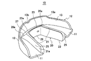
図1は、本発明の一実施形態に係る歯科矯正具を示す斜視図である。図2は、図1の平面図である。図3は、図1の背面図である。図4は、図1の正面図である。 FIG. 1 is a perspective view showing an orthodontic appliance according to an embodiment of the present invention. FIG. 2 is a plan view of FIG. FIG. 3 is a rear view of FIG. FIG. 4 is a front view of FIG.
なお、以下の実施形態では、歯科矯正具10を口腔部内に挿入し、上歯列及び下歯列に装着した状態で、その前歯側を前側、奥歯側を後側とし、前歯に対する左側、右側をそれぞれ左側、右側として説明する。ここで、前歯は、切歯であって、左右の中切歯、左右の側切歯、及び左右の犬歯を備える。奥歯は、臼歯であって、左右の第1、第2小臼歯、左右の第1〜第3大臼歯を備える。
In the following embodiment, with the
本実施形態の歯科矯正具10は、図1乃至図4に示すように、上顎の上歯列及び下顎の下歯列に装着されるマウスピース型である。本実施形態の歯科矯正具10は、上顎の上歯列及び下顎の下歯列に装着して上歯列及び下歯列を横方向に拡げるとともに、上歯列及び下歯列の個々の歯を整列すべき方向に移動させて矯正し、口腔周辺の筋機能を整えるものである。
As shown in FIGS. 1 to 4, the
本実施形態の歯科矯正具10は、全体が弾性を有する樹脂材料で一体成形されている。具体的に、上記樹脂材料は、例えばシリコン樹脂、ポリオレフィン系樹脂、スチレン系樹脂及びアクリル樹脂等から選択される。上記樹脂材料は、無色透明又は乳白色であることが望ましく、これにより口腔内に挿入した場合、上歯列及び下歯列に装着していることが目立たず、審美性に優れたものとなる。歯科矯正具10は、上歯列及び下歯列の個々の歯を整列すべき方向に徐々に移動させる形状に成型した成型物(アライナー)である。歯科矯正具10は、例えば複数異なる大きさのもの、あるいは異なる硬さのものを段階的に用意して、それらを定期的に交換することにより矯正治療を進めていくものである。
The
歯科矯正具10は、主としてベース部11と、外周壁12と、内周壁20と、を備える。ベース部11は、歯科矯正具10を口腔内に挿入したとき、上顎の上歯列及び下顎の下歯列に挟まれる部位であり、外周壁12と内周壁20との間で平面視U字状に形成されている。
The
外周壁12は、ベース部11の外周縁側に設けられ、上下方向に突出するように形成されている。外周壁12は、ベース部11よりも上方に設けられた外周上部壁13と、ベース部11よりも下方に設けられた外周下部壁14とを備えている。外周上部壁13及び外周下部壁14は、前歯の中切歯に対応する部分を中心として左右対称の形状に形成されている。
The outer
外周上部壁13は、奥歯側よりも前歯側がベース部11から若干高く形成されている。そのため、外周上部壁13は、奥歯側と前歯側との間における左右対称位置にそれぞれ頬小帯を回避するために緩やかな左右一対の段差部13aが形成されている。外周上部壁13は、左右方向の中央に上唇小帯が嵌り込むためV字状の切欠き部13bが形成されている。外周下部壁14は、図3に示すように奥歯側から前歯側にかけてベース部11に対する高さが徐々に高くなるように形成されている。
The outer peripheral
内周壁20は、ベース部11の内周縁側に設けられ、上下方向に突出するように形成されている。この上下方向に突出した内周壁20は、それぞれ平面視コ字状に形成されている。コ字状に形成された内周壁20の内周面は、ベース部11に対して垂直であって、舌部を包み込む空間を形成している。この空間が口腔内での舌を拘束することで、筋機能を整えている。
The inner
また、コ字状の両角部20aは、歯科矯正具10を装着したとき、左右の犬歯と左右の小臼歯との間に対応する位置にそれぞれ形成されている。上側及び下側のコ字状の短辺側は、前歯に対応する位置に形成され、上側及び下側の2つの長辺側は、それぞれ左右の奥歯に対応する位置に形成されている。
Further, the U-shaped both
内周壁20は、ベース部11よりも上方であって、上歯列のうち左右側の奥歯に対応する位置に設けられた左右内周上部壁(上部壁)21と、ベース部11よりも下方であって、下歯列のうち左右側の奥歯に対応する位置に設けられた左右内周下部壁(下部壁)22と、を備えている。内周壁20は、ベース部11よりも上方であって、上歯列の前歯に対応する位置に設けられた前側内周上部壁23と、ベース部11よりも下方であって、下歯列の前歯に対応する位置に設けられた前側内周下部壁24と、を備えている。
The inner
これら左右内周上部壁21及び左右内周下部壁22は、それぞれベース部11に臨む左右上部側面部(上部側面部)21a及び左右下部側面部(下部側面部)22aを有している。前側内周上部壁23及び前側内周下部壁24は、それぞれ外周壁12の最下部及び最上部まで延びる前側上部側面部23a及び前側下部側面部を有している。左右内周上部壁21と前側内周上部壁23、左右内周下部壁22と前側内周下部壁24は、それぞれ連続して形成されている。
The left and right inner peripheral
左右上部側面部21aは、上歯列の奥歯が当接可能であって、上辺からベース部11に接する下辺にいくに従って外周壁12との間隔が徐々に狭くなるような左右上部傾斜面(上部傾斜面)25が形成されている。左右下部側面部22aは、下歯列の奥歯が当接可能であって、下辺からベース部11に接する上辺にいくに従って外周壁12との間隔が徐々に狭くなるような左右下部傾斜面(下部傾斜面)26が形成されている。
The left and right upper
前側上部側面部23aは、上歯列の前歯が当接可能であって、上辺からベース部11に接する下辺にいくに従って外周壁12との間隔が徐々に狭くなるような前側上部傾斜面27が形成されている。この前側上部傾斜面27の下辺は、外周上部壁13の最下部まで延びている。前側下部側面部24aは、下歯列の前歯が当接可能であって、下辺からベース部11に接する上辺にいくに従って外周壁12との間隔が徐々に狭くなるような前側下部傾斜面28が形成されている。前側下部傾斜面28の上辺は、外周下部壁14の最上部まで延びている。
The front upper
左右上部傾斜面25及び左右下部傾斜面26は、左右の第一大臼歯に対応する最下部の間隔が36mm〜41mm(本実施形態では、37.75mm)に設定されている。このような間隔の値は、大抵の日本人が乳歯列から永久歯列に生え変わるときに、歯列を横方向に広げるとともに、歯列を矯正するために設定されている。
The distance between the lowermost portions of the left and right upper
上下方向において前側上部傾斜面27と前側下部傾斜面28との間には、左右方向に所定の間隔をおいて2つの通気孔30が形成されている。これらの通気孔30は、小児が本実施形態の歯科矯正具10を口腔内に挿入したときに、呼吸するために用いられる。
Two ventilation holes 30 are formed between the front upper
次に、本実施形態の歯科矯正具10の作用について説明する。
Next, the operation of the
本実施形態の歯科矯正具10は、乳歯列から永久歯列に生え変わる例えば生後6歳から9歳の小児に適用される。まず、歯科矯正具10を小児の口腔内に挿入し、上歯列及び下歯列に装着する。すると、上歯列及び下歯列の左右側の奥歯が左右上部傾斜面25及び左右下部傾斜面26に当接する。同時に、上歯列及び下歯列の前歯が前側上部傾斜面27及び前側下部傾斜面28に当接する。この状態で上唇と下唇が当たるように口を閉じる。これにより、口腔周辺の筋機能を発達させることで、筋機能を整えることができる。
The
また、例えば乳歯列から永久歯列に生え変わるときに、上歯列及び下歯列の左右側の奥歯が左右上部傾斜面25及び左右下部傾斜面26に当接することで、上歯列及び下歯列の左右側の奥歯が左右上部傾斜面25及び左右下部傾斜面26に案内されて徐々に横方向に広がるとともに、上歯列及び下歯列の左右側の奥歯の叢生等を矯正することが可能となる。
Further, for example, when the deciduous dentition is changed to a permanent dentition, the left and right back teeth of the upper dentition and the lower dentition come into contact with the left and right upper
同時に、上歯列及び下歯列の前歯が前側上部傾斜面27及び前側下部傾斜面28に当接することで、上歯列及び下歯列の前歯が前側上部傾斜面27及び前側下部傾斜面28に案内されて徐々に前側に広がるとともに、上歯列及び下歯列の前歯の叢生等を容易に矯正することが可能となる。
At the same time, the anterior teeth of the upper dentition and the lower dentition come into contact with the anterior upper
そして、上歯列及び下歯列の左右側の奥歯が横方向に広がり、奥歯がベース部11に当接するようになり、さらに横方向に広げようとする場合には、左右の第一大臼歯に対応する最下部の間隔がより広い他の歯科矯正具と交換するか、あるいは歯科矯正具10の素材をより硬質のものと交換するようにしてもよい。
Then, the left and right back teeth of the upper and lower dentitions spread laterally, and the back teeth come into contact with the
このように本実施形態の歯科矯正具10によれば、内周壁12は左右内周上部壁21と左右内周下部壁22とを備え、これら左右内周上部壁21及び左右内周下部壁22は、それぞれベース部11に臨む左右上部側面部21a及び左右下部側面部22aを有し、この左右上部側面部21aは、上歯列が当接可能な左右上部傾斜面25が形成され、左右下部側面部22aは、下歯列が当接可能な左右下部傾斜面26が形成されているので、上歯列が左右上部傾斜面25に当接する一方、下歯列が左右下部傾斜面26に当接することで、上歯列及び下歯列を横方向に広げるとともに、上歯列及び下歯列を矯正することができ、口腔周辺の筋機能を整えることが可能となる。例えば、乳歯列から永久歯列に生え変わるときに歯科矯正具10を装着した場合には、顕著な効果を得ることがきる。
As described above, according to the
また、本実施形態によれば、内周壁20は、平面視コ字状に形成されていることから、舌を常に正しい位置に拘束することができ、口腔周辺の筋機能を一段と整えることが可能となる。
Further, according to the present embodiment, since the inner
また、本実施形態によれば、内周壁20のコ字状の角部20aは、左右の犬歯と左右の小臼歯との間に対応する位置にそれぞれ形成されているので、歯科矯正具10を上歯列及び下歯列に確実に適合させることができる。その結果、永久歯列の拡大効果及び矯正効果を一段と高めることが可能となる。
Further, according to the present embodiment, the
また、本実施形態によれば、左右の第一大臼歯に対応する左右上部傾斜面25及び左右下部傾斜面26の左右の最下部の間隔が36mm〜41mmとしたことにより、例えば乳歯列から永久歯列に生え変わるときに、永久歯列を横方向に拡げて望ましい位置にするとともに、永久歯列を矯正することができる。
Further, according to the present embodiment, the distance between the left and right upper
また、本実施形態によれば、ベース部11、外周壁12、及び内周壁20は、弾性を有する樹脂材料で一体成形されているので、装着感を高めることが可能となる。
[発明の一実施例]
次に、図5及び図6に基づいて歯科矯正具の一実施例の各部の具体的な寸法について説明する。
Further, according to the present embodiment, since the
[Example of the invention]
Next, the specific dimensions of each part of the embodiment of the orthodontic appliance will be described with reference to FIGS. 5 and 6.
図5は、本発明の一実施例に係る歯科矯正具を示す底面図である。図6は、図5の背面図である。 FIG. 5 is a bottom view showing an orthodontic appliance according to an embodiment of the present invention. FIG. 6 is a rear view of FIG.
本実施例では、各部の寸法が以下の通りである。 In this embodiment, the dimensions of each part are as follows.
図5に示すように、外周下部壁14の一端から他端までの長さAは、68.09mm、左右内周下部壁22の一端から他端までの長さBは、29.95mm、左右内周下部壁22の内周最前部から最後部までの長さCは、31.06mm、外周壁12の外周最前部から内周壁20の内周最前部までの長さDは、10.80mm、上歯列及び下歯列の奥歯に対応する位置であって、外周壁12の外側から内周壁20の内側までの長さEは、18.35mmである。なお、上述した長さA、Bは、±3mm程度の範囲内に設定されている。
As shown in FIG. 5, the length A from one end to the other end of the outer peripheral
図6に示すように、左右内周下部壁22の最上部の一端から他端までの長さFは、37.75mm、左右内周下部壁22の最上部から外周壁12までの長さGは、15.04mm、歯科矯正具10の上下方向の高さHは、21.99mm、左右内周上部壁21の上端から左右内周下部壁22の下端までの高さIは、12.00mm、2つの通気孔30間の間隔Jは、9.79mm、1つの通気孔30の幅Kは、2.70mm、1つの通気孔30の高さLは、1.50mmである。
As shown in FIG. 6, the length F from one end to the other end of the uppermost portion of the left and right inner peripheral
左右上部傾斜面25及び左右下部傾斜面26は、それぞれベース部11に対する角度が例えば50〜70度の範囲であって、本実施例では略60度に設定されている。このような角度に設定することで、上歯列及び下歯列を横方向に広げる効果を一段と高めることができる。
The left and right upper
本実施例の歯科矯正具10は、具体的な寸法を上記のように設定したことから、6歳から9歳までの小児が装着した場合には、歯列を横方向に広げるとともに、歯列を矯正し、口腔周辺の筋機能を整えることが可能となる。
[発明の他の実施形態]
なお、上記実施形態は本発明の例示であり、本発明が上記実施形態のみに限定されることを意味するものではないことは、いうまでもない。
Since the specific dimensions of the
[Other Embodiments of the Invention]
Needless to say, the above-described embodiment is an example of the present invention and does not mean that the present invention is limited to the above-mentioned embodiment.
上記実施形態では、乳歯列から永久歯列に生え変わる小児に歯科矯正具10を装着した場合について説明したが、これに限らず例えば寸法の異なる歯科矯正具を成人に装着した場合でも、上歯列及び下歯列を横方向に広げ、上歯列及び下歯列を矯正し、口腔周辺の筋機能を整えることが可能になるという効果が得られる。
In the above embodiment, the case where the
また、上記実施形態では、歯科矯正具10の素材、形状については、口腔内に挿入することができるもので同様の機能を有するものであれば、適宜の素材で構成されていてもよい。
Further, in the above embodiment, the material and shape of the
10 歯科矯正具
11 ベース部
12 外周壁
13 外周上部壁
13a 段差部
13b 切欠き部
14 外周下部壁
20 内周壁
20a 角部
21 左右内周上部壁(上部壁)
21a 左右上部側面部(上部側面部)
22 左右内周下部壁(下部壁)
22a 左右下部側面部(下部側面部)
23 前側内周上部壁
23a 前側上部側面部
24 前側内周下部壁
24a 前側下部側面部
25 左右上部傾斜面(上部傾斜面)
26 左右下部傾斜面(下部傾斜面)
27 前側上部傾斜面
28 前側下部傾斜面
30 通気孔
10 Orthodontic braces 11
21a Left and right upper side surface (upper side surface)
22 Left and right inner circumference lower wall (lower wall)
22a Left and right lower side surface (lower side surface)
23 Front inner circumference
26 Left and right lower inclined surface (lower inclined surface)
27 Front upper
Claims (3)
前記ベース部の外周縁側に設けられ、上下方向に突出する外周壁と、
前記ベース部の内周縁側に設けられ、上下方向に突出し平面視コ字状に形成された内周壁と、を備え、
前記内周壁のコ字状の両角部は、左右の前歯と左右の奥歯との間に対応する位置にそれぞれ形成され、
前記内周壁は、前記ベース部よりも上方に設けられた上部壁と、前記ベース部よりも下方に設けられた下部壁とを備え、
前記上部壁は、前記コ字状の両角部の間に形成された前側上部側面部と、前記コ字状の両角部の前記左右の奥歯側にそれぞれ形成された左右上部側面部とを有し、
前記下部壁は、前記コ字状の両角部の間に形成された前側下部側面部と、前記コ字状の両角部の前記左右の奥歯側にそれぞれ形成された左右下部側面部とを有し、
前記前側上部側面部は、前記上歯列の前記前歯が当接可能であって、上辺から前記ベース部に接する下辺にいくに従って前記外周壁との間隔が狭くなるような前側上部傾斜面が形成され、
前記前側下部側面部は、前記下歯列の前記前歯が当接可能であって、下辺から前記ベース部に接する上辺にいくに従って前記外周壁との間隔が狭くなるような前側下部傾斜面が形成され、
前記左右上部側面部は、前記上歯列の前記奥歯が当接可能であって、上辺から前記ベース部に接する下辺にいくに従って前記外周壁との間隔が狭くなるような左右上部傾斜面が形成され、
前記左右下部側面部は、前記下歯列の前記奥歯が当接可能であって、下辺から前記ベース部に接する上辺にいくに従って前記外周壁との間隔が狭くなるような左右下部傾斜面が形成され、
前記前側上部傾斜面は、前記左右上部傾斜面よりも傾斜角度が緩やかになるように形成され、
前記前側下部傾斜面は、前記左右下部傾斜面よりも傾斜角度が緩やかになるように形成されている、
ことを特徴とする歯科矯正具。 A base part that is sandwiched between the upper dentition of the upper jaw and the lower dentition of the lower jaw and is formed in a U shape in a plan view.
An outer peripheral wall provided on the outer peripheral edge side of the base portion and projecting in the vertical direction,
An inner peripheral wall provided on the inner peripheral edge side of the base portion and protruding in the vertical direction and formed in a U-shape in a plan view is provided.
The U-shaped corners of the inner peripheral wall are formed at corresponding positions between the left and right front teeth and the left and right molars, respectively.
The inner peripheral wall includes an upper wall provided above the base portion and a lower wall provided below the base portion.
The upper wall has a front upper side surface portion formed between the U-shaped corner portions and a left and right upper side surface portion formed on the left and right back tooth sides of the U-shaped both corner portions, respectively. ,
The lower wall has a front lower side surface portion formed between the U-shaped corner portions and a left and right lower side surface portion formed on the left and right back tooth sides of the U-shaped both corner portions, respectively. ,
The front upper side surface portion is formed with a front upper inclined surface such that the front teeth of the upper dentition can be brought into contact with each other and the distance from the outer peripheral wall becomes narrower from the upper side to the lower side in contact with the base portion. Being done
The front lower side surface portion is formed with a front lower inclined surface on which the front teeth of the lower dentition can be brought into contact with each other and the distance from the outer peripheral wall becomes narrower from the lower side to the upper side in contact with the base portion. Being done
The left and right upper side surface portions are formed with left and right upper inclined surfaces so that the back teeth of the upper dentition can come into contact with each other and the distance from the outer peripheral wall becomes narrower from the upper side to the lower side in contact with the base portion. Being done
The left and right lower side surface portions are formed with left and right lower inclined surfaces so that the back teeth of the lower dentition can come into contact with each other and the distance from the outer peripheral wall becomes narrower from the lower side to the upper side in contact with the base portion. Being done
The front upper inclined surface is formed so that the inclined angle is gentler than the left and right upper inclined surfaces.
The front lower inclined surface is formed so that the inclined angle is gentler than the left and right lower inclined surfaces.
Orthodontic appliances that are characterized by that.
Priority Applications (6)
| Application Number | Priority Date | Filing Date | Title |
|---|---|---|---|
| JP2019141471A JP6875018B2 (en) | 2019-07-31 | 2019-07-31 | Orthodontics |
| PCT/JP2020/011918 WO2021019832A1 (en) | 2019-07-31 | 2020-03-18 | Orthodontic tool |
| EP20847074.0A EP4005527A4 (en) | 2019-07-31 | 2020-03-18 | Orthodontic tool |
| US17/622,115 US20220257346A1 (en) | 2019-07-31 | 2020-03-18 | Orthodontic appliance |
| CN202080048947.3A CN114072093B (en) | 2019-07-31 | 2020-03-18 | Orthodontics |
| TW109110945A TWI740437B (en) | 2019-07-31 | 2020-03-31 | Orthodontic appliances |
Applications Claiming Priority (1)
| Application Number | Priority Date | Filing Date | Title |
|---|---|---|---|
| JP2019141471A JP6875018B2 (en) | 2019-07-31 | 2019-07-31 | Orthodontics |
Publications (2)
| Publication Number | Publication Date |
|---|---|
| JP2021023419A JP2021023419A (en) | 2021-02-22 |
| JP6875018B2 true JP6875018B2 (en) | 2021-05-19 |
Family
ID=74230627
Family Applications (1)
| Application Number | Title | Priority Date | Filing Date |
|---|---|---|---|
| JP2019141471A Active JP6875018B2 (en) | 2019-07-31 | 2019-07-31 | Orthodontics |
Country Status (6)
| Country | Link |
|---|---|
| US (1) | US20220257346A1 (en) |
| EP (1) | EP4005527A4 (en) |
| JP (1) | JP6875018B2 (en) |
| CN (1) | CN114072093B (en) |
| TW (1) | TWI740437B (en) |
| WO (1) | WO2021019832A1 (en) |
Families Citing this family (1)
| Publication number | Priority date | Publication date | Assignee | Title |
|---|---|---|---|---|
| USD1057960S1 (en) * | 2023-06-26 | 2025-01-14 | Akervall Technologies, Inc. | Whitening tray for teeth |
Family Cites Families (21)
| Publication number | Priority date | Publication date | Assignee | Title |
|---|---|---|---|---|
| FR67616E (en) * | 1955-02-21 | 1958-03-14 | Orthodontic splint | |
| US3842107A (en) | 1973-07-23 | 1974-10-15 | Smithkline Corp | Phosphine or phosphite gold complexes of thiobenzoic acid and substituted thiophenols |
| FR2641964B1 (en) * | 1989-01-26 | 1998-02-20 | Besombes Andre | GUTTER ACTIVATORS FOR DENTO-FACIAL ORTHOPEDIC TREATMENTS AND PERIODONTOLOGY |
| FR2751865B1 (en) * | 1996-07-30 | 1998-10-16 | Mathieu Rodrigue | APPARATUS FOR DENTO-FACIAL FUNCTIONAL ORTHOPEDIC TREATMENT AND PERIODONTOLOGY |
| US5876199A (en) * | 1997-08-28 | 1999-03-02 | Ortho-Tain, Inc. | Appliance adapted to fit many mouth and tooth sizes for orthodontic correction and other uses |
| NZ525382A (en) * | 2002-08-30 | 2004-09-24 | Christopher John Farrell | Oral appliance suitable for use as sports guard |
| US20060084024A1 (en) * | 2004-10-14 | 2006-04-20 | Farrell Christopher J | Oral appliance |
| US7798149B2 (en) * | 2007-01-30 | 2010-09-21 | Han Haduong | Method and system for swallow control resulting in improved posture |
| KR100883168B1 (en) * | 2007-05-23 | 2009-02-10 | 정수용 | Jaw protection device |
| KR200461324Y1 (en) * | 2011-02-07 | 2012-07-12 | 이영준 | Temporomandibular Joint Balancing Appliance for Slit |
| FR2973219B1 (en) * | 2011-04-01 | 2014-04-25 | So Dis Ap F | DENTO-FACIAL FUNCTIONAL ORTHOPEDIC APPARATUS |
| JP5564079B2 (en) * | 2012-07-26 | 2014-07-30 | 淳 大塚 | Orthodontic appliance |
| CN105451681B (en) * | 2013-08-09 | 2018-09-18 | 庆熙大学校产学协力团 | Dental appliances removably mounted on teeth |
| JP2015150179A (en) * | 2014-02-14 | 2015-08-24 | キープ・アップ株式会社 | orthodontic appliance |
| US10376408B2 (en) * | 2014-08-25 | 2019-08-13 | Airway Technologies, Llc | Oral appliance |
| KR101637087B1 (en) * | 2014-10-23 | 2016-07-07 | 주식회사 진바이오테크 | Temporomandibular Joint Balancing Appliance for Cervical Correction |
| ITUB20154030A1 (en) * | 2015-09-30 | 2017-03-30 | Francesco Magistro | DENT-CRANIO-FACIAL ORTHODONTIC-ELASTIC-HARMONIZER DEVICE |
| CN107865705B (en) * | 2016-09-26 | 2023-07-07 | 上海慕港医疗科技有限公司 | Multifunctional appliance for orthodontic treatment |
| TWM550126U (en) * | 2017-06-02 | 2017-10-11 | Soo-Chang Jung | Teeth correction and temporomandibular joints balancer |
| CN208756201U (en) * | 2018-02-08 | 2019-04-19 | 陈勇 | A kind of teeth orthopedic instrument |
| CN209136919U (en) * | 2018-04-25 | 2019-07-23 | 上海慕港医疗科技有限公司 | A kind of oral multifunctional rectifier |
-
2019
- 2019-07-31 JP JP2019141471A patent/JP6875018B2/en active Active
-
2020
- 2020-03-18 CN CN202080048947.3A patent/CN114072093B/en not_active Expired - Fee Related
- 2020-03-18 US US17/622,115 patent/US20220257346A1/en not_active Abandoned
- 2020-03-18 WO PCT/JP2020/011918 patent/WO2021019832A1/en not_active Ceased
- 2020-03-18 EP EP20847074.0A patent/EP4005527A4/en not_active Withdrawn
- 2020-03-31 TW TW109110945A patent/TWI740437B/en active
Also Published As
| Publication number | Publication date |
|---|---|
| TWI740437B (en) | 2021-09-21 |
| US20220257346A1 (en) | 2022-08-18 |
| CN114072093B (en) | 2022-09-09 |
| WO2021019832A1 (en) | 2021-02-04 |
| EP4005527A4 (en) | 2022-12-28 |
| JP2021023419A (en) | 2021-02-22 |
| CN114072093A (en) | 2022-02-18 |
| TW202106258A (en) | 2021-02-16 |
| EP4005527A1 (en) | 2022-06-01 |
Similar Documents
| Publication | Publication Date | Title |
|---|---|---|
| US4799884A (en) | Expansion/buccal shield appliance | |
| AU2003270816B2 (en) | A dental appliance having an altered vertical thickness between an upper shell and a lower shell with an integrared hinging mechanism to attach an upper shell and lower shell and system and method for treating malocclusions | |
| US5203695A (en) | Orthodontic device for expansion of arches with imbedded wire | |
| KR101676584B1 (en) | Clear aligner system | |
| CA1059350A (en) | Orthodontic positioner with overbite or open bite correcting or relapse inhibiting capability | |
| US20180078342A1 (en) | Dental Appliance For Use as an Aligner and as a Tool to Reduce Temporomandibular Dysfunction | |
| KR102202863B1 (en) | Orthodontic appliance with mandibular orthopaedic function | |
| JP5564079B2 (en) | Orthodontic appliance | |
| JP5623472B2 (en) | Orthodontic appliance | |
| JP6736614B2 (en) | Orthodontic device | |
| JP2022507499A5 (en) | ||
| US20240024078A1 (en) | Clear Plastic Aligner with Configurable Protrusions For Anterior Or Open Bite Treatment And Mattress Plastic Material For Invisible Aligners | |
| TWI750097B (en) | Orthodontic device | |
| JP6875018B2 (en) | Orthodontics | |
| JP6557637B2 (en) | Orthodontic appliance | |
| JP7295580B1 (en) | orthodontic appliance | |
| JP6963855B1 (en) | Orthodontics | |
| JP6902301B1 (en) | Muscle function therapy device | |
| JP7020727B1 (en) | Orthodontics | |
| JP6945111B1 (en) | Orthodontic appliance | |
| JP3200643U (en) | Chin orthodontic appliance | |
| US20230040228A1 (en) | Overlapping canines and laterals dentition appliance | |
| JP2023131444A (en) | Orthodontic tool |
Legal Events
| Date | Code | Title | Description |
|---|---|---|---|
| A621 | Written request for application examination |
Free format text: JAPANESE INTERMEDIATE CODE: A621 Effective date: 20200630 |
|
| A871 | Explanation of circumstances concerning accelerated examination |
Free format text: JAPANESE INTERMEDIATE CODE: A871 Effective date: 20200630 |
|
| A975 | Report on accelerated examination |
Free format text: JAPANESE INTERMEDIATE CODE: A971005 Effective date: 20200907 |
|
| A131 | Notification of reasons for refusal |
Free format text: JAPANESE INTERMEDIATE CODE: A131 Effective date: 20201006 |
|
| A521 | Request for written amendment filed |
Free format text: JAPANESE INTERMEDIATE CODE: A523 Effective date: 20201201 |
|
| A131 | Notification of reasons for refusal |
Free format text: JAPANESE INTERMEDIATE CODE: A131 Effective date: 20210309 |
|
| A521 | Request for written amendment filed |
Free format text: JAPANESE INTERMEDIATE CODE: A523 Effective date: 20210322 |
|
| TRDD | Decision of grant or rejection written | ||
| A01 | Written decision to grant a patent or to grant a registration (utility model) |
Free format text: JAPANESE INTERMEDIATE CODE: A01 Effective date: 20210413 |
|
| A61 | First payment of annual fees (during grant procedure) |
Free format text: JAPANESE INTERMEDIATE CODE: A61 Effective date: 20210415 |
|
| R150 | Certificate of patent or registration of utility model |
Ref document number: 6875018 Country of ref document: JP Free format text: JAPANESE INTERMEDIATE CODE: R150 |
|
| S533 | Written request for registration of change of name |
Free format text: JAPANESE INTERMEDIATE CODE: R313533 |
|
| R350 | Written notification of registration of transfer |
Free format text: JAPANESE INTERMEDIATE CODE: R350 |
|
| S531 | Written request for registration of change of domicile |
Free format text: JAPANESE INTERMEDIATE CODE: R313531 |
|
| R350 | Written notification of registration of transfer |
Free format text: JAPANESE INTERMEDIATE CODE: R350 |
|
| R250 | Receipt of annual fees |
Free format text: JAPANESE INTERMEDIATE CODE: R250 |
|
| R250 | Receipt of annual fees |
Free format text: JAPANESE INTERMEDIATE CODE: R250 |