JP6876490B2 - 直動案内ユニット - Google Patents
直動案内ユニット Download PDFInfo
- Publication number
- JP6876490B2 JP6876490B2 JP2017071808A JP2017071808A JP6876490B2 JP 6876490 B2 JP6876490 B2 JP 6876490B2 JP 2017071808 A JP2017071808 A JP 2017071808A JP 2017071808 A JP2017071808 A JP 2017071808A JP 6876490 B2 JP6876490 B2 JP 6876490B2
- Authority
- JP
- Japan
- Prior art keywords
- casing
- roller
- linear motion
- track
- path
- Prior art date
- Legal status (The legal status is an assumption and is not a legal conclusion. Google has not performed a legal analysis and makes no representation as to the accuracy of the status listed.)
- Active
Links
Images




Classifications
-
- F—MECHANICAL ENGINEERING; LIGHTING; HEATING; WEAPONS; BLASTING
- F16—ENGINEERING ELEMENTS AND UNITS; GENERAL MEASURES FOR PRODUCING AND MAINTAINING EFFECTIVE FUNCTIONING OF MACHINES OR INSTALLATIONS; THERMAL INSULATION IN GENERAL
- F16C—SHAFTS; FLEXIBLE SHAFTS; ELEMENTS OR CRANKSHAFT MECHANISMS; ROTARY BODIES OTHER THAN GEARING ELEMENTS; BEARINGS
- F16C29/00—Bearings for parts moving only linearly
- F16C29/04—Ball or roller bearings
- F16C29/06—Ball or roller bearings in which the rolling bodies circulate partly without carrying load
- F16C29/063—Ball or roller bearings in which the rolling bodies circulate partly without carrying load with a bearing body, e.g. a carriage or part thereof, provided between the legs of a U-shaped guide rail or track
-
- F—MECHANICAL ENGINEERING; LIGHTING; HEATING; WEAPONS; BLASTING
- F16—ENGINEERING ELEMENTS AND UNITS; GENERAL MEASURES FOR PRODUCING AND MAINTAINING EFFECTIVE FUNCTIONING OF MACHINES OR INSTALLATIONS; THERMAL INSULATION IN GENERAL
- F16C—SHAFTS; FLEXIBLE SHAFTS; ELEMENTS OR CRANKSHAFT MECHANISMS; ROTARY BODIES OTHER THAN GEARING ELEMENTS; BEARINGS
- F16C29/00—Bearings for parts moving only linearly
- F16C29/04—Ball or roller bearings
- F16C29/045—Ball or roller bearings having rolling elements journaled in one of the moving parts
- F16C29/046—Ball or roller bearings having rolling elements journaled in one of the moving parts with balls journaled in pockets
-
- F—MECHANICAL ENGINEERING; LIGHTING; HEATING; WEAPONS; BLASTING
- F16—ENGINEERING ELEMENTS AND UNITS; GENERAL MEASURES FOR PRODUCING AND MAINTAINING EFFECTIVE FUNCTIONING OF MACHINES OR INSTALLATIONS; THERMAL INSULATION IN GENERAL
- F16C—SHAFTS; FLEXIBLE SHAFTS; ELEMENTS OR CRANKSHAFT MECHANISMS; ROTARY BODIES OTHER THAN GEARING ELEMENTS; BEARINGS
- F16C29/00—Bearings for parts moving only linearly
- F16C29/04—Ball or roller bearings
- F16C29/06—Ball or roller bearings in which the rolling bodies circulate partly without carrying load
- F16C29/0602—Details of the bearing body or carriage or parts thereof, e.g. methods for manufacturing or assembly
- F16C29/0604—Details of the bearing body or carriage or parts thereof, e.g. methods for manufacturing or assembly of the load bearing section
- F16C29/0607—Details of the bearing body or carriage or parts thereof, e.g. methods for manufacturing or assembly of the load bearing section of parts or members for retaining the rolling elements, i.e. members to prevent the rolling elements from falling out of the bearing body or carriage
-
- F—MECHANICAL ENGINEERING; LIGHTING; HEATING; WEAPONS; BLASTING
- F16—ENGINEERING ELEMENTS AND UNITS; GENERAL MEASURES FOR PRODUCING AND MAINTAINING EFFECTIVE FUNCTIONING OF MACHINES OR INSTALLATIONS; THERMAL INSULATION IN GENERAL
- F16C—SHAFTS; FLEXIBLE SHAFTS; ELEMENTS OR CRANKSHAFT MECHANISMS; ROTARY BODIES OTHER THAN GEARING ELEMENTS; BEARINGS
- F16C29/00—Bearings for parts moving only linearly
- F16C29/04—Ball or roller bearings
- F16C29/06—Ball or roller bearings in which the rolling bodies circulate partly without carrying load
- F16C29/0602—Details of the bearing body or carriage or parts thereof, e.g. methods for manufacturing or assembly
- F16C29/0609—Details of the bearing body or carriage or parts thereof, e.g. methods for manufacturing or assembly of the ends of the bearing body or carriage where the rolling elements change direction, e.g. end caps
-
- F—MECHANICAL ENGINEERING; LIGHTING; HEATING; WEAPONS; BLASTING
- F16—ENGINEERING ELEMENTS AND UNITS; GENERAL MEASURES FOR PRODUCING AND MAINTAINING EFFECTIVE FUNCTIONING OF MACHINES OR INSTALLATIONS; THERMAL INSULATION IN GENERAL
- F16C—SHAFTS; FLEXIBLE SHAFTS; ELEMENTS OR CRANKSHAFT MECHANISMS; ROTARY BODIES OTHER THAN GEARING ELEMENTS; BEARINGS
- F16C29/00—Bearings for parts moving only linearly
- F16C29/04—Ball or roller bearings
- F16C29/06—Ball or roller bearings in which the rolling bodies circulate partly without carrying load
- F16C29/0602—Details of the bearing body or carriage or parts thereof, e.g. methods for manufacturing or assembly
- F16C29/0611—Details of the bearing body or carriage or parts thereof, e.g. methods for manufacturing or assembly of the return passages, i.e. the passages where the rolling elements do not carry load
-
- F—MECHANICAL ENGINEERING; LIGHTING; HEATING; WEAPONS; BLASTING
- F16—ENGINEERING ELEMENTS AND UNITS; GENERAL MEASURES FOR PRODUCING AND MAINTAINING EFFECTIVE FUNCTIONING OF MACHINES OR INSTALLATIONS; THERMAL INSULATION IN GENERAL
- F16C—SHAFTS; FLEXIBLE SHAFTS; ELEMENTS OR CRANKSHAFT MECHANISMS; ROTARY BODIES OTHER THAN GEARING ELEMENTS; BEARINGS
- F16C29/00—Bearings for parts moving only linearly
- F16C29/04—Ball or roller bearings
- F16C29/06—Ball or roller bearings in which the rolling bodies circulate partly without carrying load
- F16C29/0633—Ball or roller bearings in which the rolling bodies circulate partly without carrying load with a bearing body defining a U-shaped carriage, i.e. surrounding a guide rail or track on three sides
- F16C29/0635—Ball or roller bearings in which the rolling bodies circulate partly without carrying load with a bearing body defining a U-shaped carriage, i.e. surrounding a guide rail or track on three sides whereby the return paths are provided as bores in a main body of the U-shaped carriage, e.g. the main body of the U-shaped carriage is a single part with end caps provided at each end
- F16C29/065—Ball or roller bearings in which the rolling bodies circulate partly without carrying load with a bearing body defining a U-shaped carriage, i.e. surrounding a guide rail or track on three sides whereby the return paths are provided as bores in a main body of the U-shaped carriage, e.g. the main body of the U-shaped carriage is a single part with end caps provided at each end with rollers
-
- F—MECHANICAL ENGINEERING; LIGHTING; HEATING; WEAPONS; BLASTING
- F16—ENGINEERING ELEMENTS AND UNITS; GENERAL MEASURES FOR PRODUCING AND MAINTAINING EFFECTIVE FUNCTIONING OF MACHINES OR INSTALLATIONS; THERMAL INSULATION IN GENERAL
- F16C—SHAFTS; FLEXIBLE SHAFTS; ELEMENTS OR CRANKSHAFT MECHANISMS; ROTARY BODIES OTHER THAN GEARING ELEMENTS; BEARINGS
- F16C29/00—Bearings for parts moving only linearly
- F16C29/12—Arrangements for adjusting play
- F16C29/123—Arrangements for adjusting play using elastic means
Landscapes
- Engineering & Computer Science (AREA)
- General Engineering & Computer Science (AREA)
- Mechanical Engineering (AREA)
- Bearings For Parts Moving Linearly (AREA)
Description
前記ケーシングには,前記ローラの一方の端面を案内する第1案内面が前記長手方向に延びる前記軌道路に沿って形成されていると共に,前記第2軌道面の両端部に前記ローラが前記軌道路の無負荷路から負荷路に滑らかに侵入可能になる緩やかなカーブで形成されたクラウニング部がそれぞれ形成されており,
前記保持板には,前記ローラの他方の端面を案内する第2案内面が形成されると共に,前記ケーシングの前記クラウニング部に対向する前記保持板の両端部に前記第2案内面より突出した突出部がそれぞれ形成されており,
前記方向転換路から前記軌道路へ転走する前記ローラは,前記突出部によって前記第1案内面の方向に押圧されて,前記ローラの軸心が前記ケーシングの前記クラウニング部の入口側で前記第1案内面に対して直交状態の姿勢にそれぞれ整列させて前記ローラのスキューの発生を防止することを特徴とする直動案内ユニットに関する。
2 スライダ
3 ケーシング
4 エンドキャップ
5 ローラ(転動体)
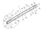
7 保持板
10 クラウニング部
11 片持梁状保持部
12 保持部材
13 固定部材
14 軌道路
15 リターン路
16 方向転換路
17 循環路
18 こま部材
21 軌道面(第1軌道面)
22 軌道面(第2軌道面)
23 側面
25,26 端面
27 端部
30 突出部
31 案内面(第1案内面)
32 案内面(第2案内面)
33 尖端部
34,53 貫通孔
36 凹状係止溝
37 傾斜面(第1傾斜面)
38 傾斜面(第2傾斜面)
40 ばね部材
41 固定ボルト
42 取付けねじ孔
43 負荷路
44 無負荷路
45 スリット
46 傾斜面
47 頂部
50 凹溝
51 切欠き部
Claims (12)
- 長手方向両側面に沿って第1軌道面がそれぞれ形成された軌道レール,前記軌道レールに跨架して前記第1軌道面に対向して第2軌道面がそれぞれ形成され且つ前記第1軌道面と前記第2軌道面とから成る軌道路を転走する転動体であるローラを介して相対移動するスライダから成り,
前記スライダは,前記第2軌道面と前記第2軌道面に平行に伸びるリターン路を備えたケーシング,前記ケーシングの長手方向の両端面にそれぞれ固着されたエンドキャップ,前記軌道路,前記リターン路及び前記軌道路と前記リターン路とを連通する前記エンドキャップに形成された方向転換路から構成される循環路を転走する前記ローラ,並びに前記軌道路に沿って配置され且つ前記ローラを前記スライダに保持する保持板を有していることから成る直動案内ユニットにおいて,
前記ケーシングには,前記ローラの一方の端面を案内する第1案内面が前記長手方向に延びる前記軌道路に沿って形成されていると共に,前記第2軌道面の両端部に前記ローラが前記軌道路の無負荷路から負荷路に滑らかに侵入可能になる緩やかなカーブで形成されたクラウニング部がそれぞれ形成されており,
前記保持板には,前記ローラの他方の端面を案内する第2案内面が形成されると共に,前記ケーシングの前記クラウニング部に対向する前記保持板の両端部に前記第2案内面より突出した突出部がそれぞれ形成されており,
前記方向転換路から前記軌道路へ転走する前記ローラは,前記突出部によって前記第1案内面の方向に押圧されて,前記ローラの軸心が前記ケーシングの前記クラウニング部の入口側で前記第1案内面に対して直交状態の姿勢にそれぞれ整列させて前記ローラのスキューの発生を防止することを特徴とする直動案内ユニット。 - 前記保持板の上下の前記第2案内面間の前記長手方向に沿って形成された前記保持板の断面V字形状の凸部でなる尖端部は,前記ケーシングの上下の前記第2軌道面間に前記長手方向に沿って形成された断面V字状の凹状係止溝に嵌入されており,前記ケーシングの袖部の取付け孔に挿通した固定ボルトを前記保持板に形成された取付けねじ孔に螺入して前記保持板が前記ケーシングに固定されていることを特徴とする請求項1に記載の直動案内ユニット。
- 前記保持板は,前記ローラの他方の前記端面をガイドする前記第2案内面が形成されている合成樹脂製の保持部材,前記保持部材の前記第2案内面の背面側に形成された凹溝に嵌入して前記保持部材を前記ケーシングに固定する金属製の固定部材,及び前記保持部材の長手方向の予め決められた複数の位置が切り欠かれた切欠き部に配置され且つ前記固定部材と前記ケーシングとの間を予め決められた所定の間隔に設定する金属製のこま部材から構成されていることを特徴とする請求項2に記載の直動案内ユニット。
- 前記保持部材は長手方向に直交する断面が山型に形成され,前記山型の傾斜面は平面状に形成された前記第2案内面を構成しており,前記山型の頂部が前記ケーシングの前記凹状係止溝に嵌入されており,前記固定部材には長手方向に隔置して複数のねじ孔が形成されており,前記ねじ孔に対応する位置の前記保持板と前記ケーシングには貫通孔が形成され,前記ケーシングの外側から前記貫通孔に固定ボルトを嵌挿して前記ねじ孔に螺入して前記保持板が前記ケーシングに固定されることを特徴とする請求項3に記載の直動案内ユニット。
- 前記保持部材の前記端部の中間位置に長手方向に延びるスリットが形成され,前記スリットの両側に一対の弾性変形可能な片持梁状保持部が形成されており,前記軌道路を転走する上下の前記ローラがそれぞれの前記片持梁状保持部を通過する際に,前記片持梁状保持部が前記ローラの端面を前記ケーシングの前記第1案内面へとそれぞれ押圧して前記ローラの前記姿勢にそれぞれ整列させることを特徴とする請求項3又は4に記載の直動案内ユニット。
- 前記スリットは,前記保持板の端部から前記軌道路の負荷域に達しており,前記クラウニング部よりも長く形成されていることを特徴とする請求項5に記載の直動案内ユニット。
- 前記保持部材には,前記片持梁状保持部を拡開方向にそれぞれ押圧するばね部材が前記片持梁状保持部間に配設されていることを特徴とする請求項5又は6に記載の直動案内ユニット。
- 前記第2案内面に沿って延びる前記突出部の長さは,前記ローラのローラ径の2〜3倍に設定されていることを特徴とする請求項1〜7のいずれか1項に記載の直動案内ユニット。
- 前記突出部の前記端部は,前記第2案内面と前記突出部の頂部を結ぶ傾斜面がそれぞれ形成されて長手方向の断面形状が台形状に形成されており,前記突出部の前記第1案内面に対向する部分が前記第1案内面と平行な平面に形成され,前記傾斜面の前記方向転換路側の第1傾斜面の傾斜角度が前記軌道路側の第2傾斜面の傾斜角度よりも小さく形成されていることを特徴とする請求項1〜8のいずれか1項に記載の直動案内ユニット。
- 前記第1傾斜面の長手方向の長さは前記ローラのローラ径の1.5倍以上に形成され,前記第2傾斜面の長手方向の長さは前記ローラのローラ径の0.5倍以上に形成されていることを特徴とする請求項9に記載の直動案内ユニット。
- 前記突出部は,前記ケーシングに形成された前記クラウニング部の端部側の無負荷域から負荷域に達する領域まで延びて形成されていることを特徴とする請求項1〜10のいずれか1項に記載の直動案内ユニット。
- 前記突出部は前記ケーシングの前記第2軌道面側に形成され,前記保持板の長手方向に対して直交する方向の前記突出部の幅は,前記ローラのローラ径の0.5倍に形成されていることを特徴とする請求項9〜11のいずれか1項に記載の直動案内ユニット。
Priority Applications (2)
| Application Number | Priority Date | Filing Date | Title |
|---|---|---|---|
| JP2017071808A JP6876490B2 (ja) | 2017-03-31 | 2017-03-31 | 直動案内ユニット |
| US15/939,729 US10408261B2 (en) | 2017-03-31 | 2018-03-29 | Linear motion guide unit |
Applications Claiming Priority (1)
| Application Number | Priority Date | Filing Date | Title |
|---|---|---|---|
| JP2017071808A JP6876490B2 (ja) | 2017-03-31 | 2017-03-31 | 直動案内ユニット |
Publications (3)
| Publication Number | Publication Date |
|---|---|
| JP2018173132A JP2018173132A (ja) | 2018-11-08 |
| JP2018173132A5 JP2018173132A5 (ja) | 2020-04-09 |
| JP6876490B2 true JP6876490B2 (ja) | 2021-05-26 |
Family
ID=63669179
Family Applications (1)
| Application Number | Title | Priority Date | Filing Date |
|---|---|---|---|
| JP2017071808A Active JP6876490B2 (ja) | 2017-03-31 | 2017-03-31 | 直動案内ユニット |
Country Status (2)
| Country | Link |
|---|---|
| US (1) | US10408261B2 (ja) |
| JP (1) | JP6876490B2 (ja) |
Families Citing this family (3)
| Publication number | Priority date | Publication date | Assignee | Title |
|---|---|---|---|---|
| CN109973519A (zh) * | 2019-04-07 | 2019-07-05 | 苏州华正工业科技有限公司 | 正压力重载柱滚动导轨副 |
| JP7219240B2 (ja) * | 2020-02-28 | 2023-02-07 | 日本トムソン株式会社 | 直動案内ユニット |
| CN120170706B (zh) * | 2025-04-02 | 2026-03-17 | 济南奥普瑞思智能装备有限公司 | 一种适用于重型工件搬运的桁架机器人 |
Family Cites Families (13)
| Publication number | Priority date | Publication date | Assignee | Title |
|---|---|---|---|---|
| JP2918429B2 (ja) | 1993-09-27 | 1999-07-12 | 日本トムソン株式会社 | 直動転がり案内ユニット |
| JP4430192B2 (ja) * | 2000-02-18 | 2010-03-10 | Thk株式会社 | 転がり案内装置 |
| JP4295573B2 (ja) * | 2003-07-24 | 2009-07-15 | 日本トムソン株式会社 | 直動案内ユニット |
| US7204036B2 (en) * | 2003-10-09 | 2007-04-17 | Nsk Ltd. | Linear guide apparatus |
| JP4469711B2 (ja) * | 2004-12-08 | 2010-05-26 | 日本トムソン株式会社 | 保持器を備えた直動案内ユニット |
| JP4551892B2 (ja) * | 2006-10-30 | 2010-09-29 | 日本トムソン株式会社 | 直動案内ユニット |
| JP5044461B2 (ja) * | 2008-03-26 | 2012-10-10 | 日本トムソン株式会社 | 直動案内ユニット |
| JP5223713B2 (ja) * | 2009-02-12 | 2013-06-26 | 日本精工株式会社 | 直動案内装置 |
| JP5440001B2 (ja) * | 2009-07-17 | 2014-03-12 | 日本精工株式会社 | 直動案内装置 |
| JP6236226B2 (ja) | 2013-05-31 | 2017-11-22 | 日本トムソン株式会社 | 保持板を備えた直動案内ユニット |
| TWI504819B (zh) * | 2013-06-19 | 2015-10-21 | Chieftech Prec Co Ltd | 滑座組合件 |
| US9022654B2 (en) * | 2013-09-27 | 2015-05-05 | Ome Technology Co., Ltd. | Linear guideway and end cap module thereof |
| JP6499885B2 (ja) * | 2015-03-06 | 2019-04-10 | 日本トムソン株式会社 | 直動案内ユニット |
-
2017
- 2017-03-31 JP JP2017071808A patent/JP6876490B2/ja active Active
-
2018
- 2018-03-29 US US15/939,729 patent/US10408261B2/en active Active
Also Published As
| Publication number | Publication date |
|---|---|
| JP2018173132A (ja) | 2018-11-08 |
| US20180283450A1 (en) | 2018-10-04 |
| US10408261B2 (en) | 2019-09-10 |
Similar Documents
| Publication | Publication Date | Title |
|---|---|---|
| JP6895811B2 (ja) | 直動案内ユニット | |
| JP5044461B2 (ja) | 直動案内ユニット | |
| JP6876490B2 (ja) | 直動案内ユニット | |
| EP2642143A1 (en) | Direct-acting guide bearing apparatus and seal member used therein | |
| JPH0560131A (ja) | 有限直動転がり案内ユニツトの保持器 | |
| WO2021172265A1 (ja) | 直動案内ユニット | |
| US7210849B2 (en) | Sliding apparatus | |
| US10316889B2 (en) | Finite linear motion guide unit having retainer straying prevention mechanism | |
| JP7186580B2 (ja) | 旋回軸受 | |
| JP6236226B2 (ja) | 保持板を備えた直動案内ユニット | |
| US10018226B2 (en) | Linear motion guide unit | |
| JP2021134903A5 (ja) | ||
| JP2018173132A5 (ja) | ||
| JP4562140B2 (ja) | 繋ぎ用軌道レールを備えた直動案内ユニット | |
| KR102156050B1 (ko) | 조합 원통롤러베어링 | |
| JP5223713B2 (ja) | 直動案内装置 | |
| JP6733075B2 (ja) | ころ軸受 | |
| WO2022239569A1 (ja) | 転動案内装置 | |
| JP5092098B2 (ja) | 直動案内装置 | |
| KR20110032808A (ko) | V자형 평판 케이지를 구비하는 복열 직선운동 베어링 | |
| JP2025071471A (ja) | 直動案内ユニット | |
| KR101631462B1 (ko) | 가이드 장치 | |
| IT8520669A1 (it) | Cuscinetto a rulli per moto lineare | |
| JP2024027844A (ja) | 直動案内ユニット | |
| JP7027274B2 (ja) | 有限直動案内ユニット |
Legal Events
| Date | Code | Title | Description |
|---|---|---|---|
| A521 | Request for written amendment filed |
Free format text: JAPANESE INTERMEDIATE CODE: A523 Effective date: 20170531 |
|
| A521 | Request for written amendment filed |
Free format text: JAPANESE INTERMEDIATE CODE: A523 Effective date: 20200228 |
|
| A621 | Written request for application examination |
Free format text: JAPANESE INTERMEDIATE CODE: A621 Effective date: 20200228 |
|
| RD03 | Notification of appointment of power of attorney |
Free format text: JAPANESE INTERMEDIATE CODE: A7423 Effective date: 20201016 |
|
| RD04 | Notification of resignation of power of attorney |
Free format text: JAPANESE INTERMEDIATE CODE: A7424 Effective date: 20201025 |
|
| A521 | Request for written amendment filed |
Free format text: JAPANESE INTERMEDIATE CODE: A523 Effective date: 20201128 |
|
| A131 | Notification of reasons for refusal |
Free format text: JAPANESE INTERMEDIATE CODE: A131 Effective date: 20210202 |
|
| A521 | Request for written amendment filed |
Free format text: JAPANESE INTERMEDIATE CODE: A523 Effective date: 20210316 |
|
| TRDD | Decision of grant or rejection written | ||
| A01 | Written decision to grant a patent or to grant a registration (utility model) |
Free format text: JAPANESE INTERMEDIATE CODE: A01 Effective date: 20210420 |
|
| A61 | First payment of annual fees (during grant procedure) |
Free format text: JAPANESE INTERMEDIATE CODE: A61 Effective date: 20210426 |
|
| R150 | Certificate of patent or registration of utility model |
Ref document number: 6876490 Country of ref document: JP Free format text: JAPANESE INTERMEDIATE CODE Ref document number: 6876490 Country of ref document: JP Free format text: JAPANESE INTERMEDIATE CODE: R150 |
|
| R250 | Receipt of annual fees |
Free format text: JAPANESE INTERMEDIATE CODE: R250 |