JP6877288B2 - Spray nozzle - Google Patents
Spray nozzle Download PDFInfo
- Publication number
- JP6877288B2 JP6877288B2 JP2017148089A JP2017148089A JP6877288B2 JP 6877288 B2 JP6877288 B2 JP 6877288B2 JP 2017148089 A JP2017148089 A JP 2017148089A JP 2017148089 A JP2017148089 A JP 2017148089A JP 6877288 B2 JP6877288 B2 JP 6877288B2
- Authority
- JP
- Japan
- Prior art keywords
- flow path
- nozzle
- rectifying
- core
- nozzle holder
- Prior art date
- Legal status (The legal status is an assumption and is not a legal conclusion. Google has not performed a legal analysis and makes no representation as to the accuracy of the status listed.)
- Active
Links
Images


Landscapes
- Nozzles (AREA)
Description
本発明は、薬液と空気とを混合した混合流体を散布する噴霧ノズルに関するものである。 The present invention relates to a spray nozzle for spraying a mixed fluid in which a chemical solution and air are mixed.
従来、薬液と空気とを混合した混合流体を散布するための噴霧ノズルが知られている。例えば、特許文献1には、液体が流れる流路及びこの流路に外部から空気を取り入れる空気取り入れ口を備えたノズルホルダと、このノズルホルダの内部に配置され、小孔を形成したオリフィス板と、ノズルホルダの上部(下流側)に取付けられた外噴板とを備えた噴霧ノズルが開示されている。この噴霧ノズルは、圧送管から流れた薬液がオリフィス板の小孔を通り、空気取り入れ口から外部の空気と液体とを混合して、流路に流れ、外噴板から一方向に向かって噴霧される。
Conventionally, a spray nozzle for spraying a mixed fluid in which a chemical solution and air are mixed is known. For example,
また、図10に示す噴霧ノズル101では、ノズル本体102が下流側で二股状に分岐しており、混合流体を二方向に散布することを可能にしている。この二方向に散布する1噴霧ノズル101の噴霧パターンは、第1噴射口103及び第2噴射口104を正面視したとき(図10(a)参照)、第1噴射口103及び第2噴射口104からの混合流体が細長い線状に噴霧されており、第1噴射口103及び第2噴射口104を側面視したとき(図10(b)参照)、第1噴射口103及び第2噴射口104からの混合流体が広い扇状に噴霧さている。
Further, in the
しかしながら、特許文献1に記載された噴霧ノズルでは、次のような問題がある。
この従来例では、オリフィス板の小孔の径が小さいため、小孔を通過した薬液と外部の空気との混合が不安定になることがある。これにより、外噴板から噴霧される混合流体の粒子がばらつき、更に、噴霧された混合流体が空気中に浮遊し、風によって漂流飛散する、いわゆる、ドリフト現象が起き、噴霧パターンが乱れてしまう虞がある。
However, the spray nozzle described in
In this conventional example, since the diameter of the small hole of the orifice plate is small, the mixing of the chemical solution that has passed through the small hole and the outside air may become unstable. As a result, the particles of the mixed fluid sprayed from the outer injection plate are dispersed, and the sprayed mixed fluid is suspended in the air, drifting and scattering due to the wind, a so-called drift phenomenon occurs, and the spray pattern is disturbed. There is a risk.
一方、図10に示される二方向に噴霧する噴霧ノズルでは、混合流体が前後二層になって広い扇状に噴霧さているため、風によって漂流飛散し、噴霧パターンが乱れてしまう虞がある。 On the other hand, in the spray nozzle for spraying in two directions shown in FIG. 10, since the mixed fluid is sprayed in a wide fan shape in two layers in the front and rear, there is a risk that the spray pattern will be disturbed by drifting and scattering due to the wind.
本発明は、上記課題に鑑みてなされたものであり、薬液と空気との混合が安定し、噴霧された混合流体が漂流飛散し難くした噴霧ノズルを提供することにある。 The present invention has been made in view of the above problems, and an object of the present invention is to provide a spray nozzle in which a mixture of a chemical solution and air is stable and the sprayed mixed fluid is less likely to drift and scatter.
(発明の態様)
以下の発明の態様は、本発明の態様を例示するものであり、本発明の多様な構成要素の理解を容易にするために、項分けして説明するものである。以下の各項は、本発明の技術的範囲を限定するものではなく、本発明を実施する最良の形態を参酌しつつ、各項の構成要素の一部を置換し、削除し、または、さらに他の構成要素を付加した態様についても、本発明の一態様になり得るものである。
(Aspect of the invention)
The following aspects of the invention exemplify aspects of the present invention and are described separately in order to facilitate understanding of the various components of the present invention. The following sections do not limit the technical scope of the present invention, and some of the components of each section are replaced, deleted, or further, while taking into consideration the best mode for carrying out the present invention. A mode in which other components are added can also be a mode of the present invention.
(1)薬液と空気とを混合した混合流体を霧状に散布する噴霧ノズルであって、
基端側に配置され、前記薬液と前記空気とが混合する混合室と、該混合室から先端側に延びる流路と、前記混合室内に外部から空気を導入する導入路とが形成されたノズルホルダと、
前記ノズルホルダの先端側に配置され、前記流路から前記混合流体を受けて、前記混合流体を噴射するスリットが形成された先噴板と、
前記ノズルホルダの先端に前記先噴板を保持するノズルキャップと、
前記先噴板と前記ノズルホルダとの間に配置され、前記流路から前記混合流体を受けて、前記混合流体を前記先噴板の前記スリットへと案内する複数の案内流路が形成された整流中子と、
前記混合室の前記流路と前記導入路との合流位置よりも前記流路の上流側に配置され、かつ、上流側から前記薬液を受けて前記混合室に前記薬液を供給するピンホールが形成されたオリフィス板と、
前記オリフィス板よりも前記流路の上流側に設けられ、前記オリフィス板と前記ノズルホルダと連結される連結具に設けられるフィルタとの間に配置され、前記薬液が流れる薬液流路が形成されたオリフィス中子と、を備え、
前記先噴板には、下流側に向けて筋状に突出する筋状絞り部が形成され、該筋状絞り部を横切る態様で前記スリットが形成されており、
前記整流中子には、前記先噴板の前記スリットに向けて先端幅が縮小する態様で整流突起部が形成され、かつ、該整流突起部を構成する壁面が前記複数の案内流路を構成する壁面の下流側に配置されており、
前記オリフィス板には、下流側へ向けてドーム状に突出するドーム状絞り部が形成され、該ドーム状絞り部の頂部に前記ピンホールが形成されている噴霧ノズル(請求項1)。
(1) A spray nozzle that sprays a mixed fluid in which a chemical solution and air are mixed in a mist form.
A nozzle arranged on the base end side and formed with a mixing chamber in which the chemical solution and the air are mixed, a flow path extending from the mixing chamber to the tip side, and an introduction path for introducing air into the mixing chamber from the outside. With the holder
A front injection plate arranged on the tip end side of the nozzle holder and formed with a slit for receiving the mixed fluid from the flow path and injecting the mixed fluid.
A nozzle cap that holds the tip jet plate at the tip of the nozzle holder,
A plurality of guide flow paths are formed which are arranged between the front injection plate and the nozzle holder, receive the mixed fluid from the flow path, and guide the mixed fluid to the slit of the front injection plate. With the rectifying core,
A pinhole is formed which is arranged on the upstream side of the flow path from the confluence position of the flow path and the introduction path of the mixing chamber and receives the chemical solution from the upstream side and supplies the chemical solution to the mixing chamber. Orifice plate and
A chemical liquid flow path is formed which is provided on the upstream side of the flow path with respect to the orifice plate and is arranged between the orifice plate and a filter provided in a connector connected to the nozzle holder to allow the chemical liquid to flow. With an orifice core,
The front jet plate is formed with a streak-shaped throttle portion that protrudes in a streak shape toward the downstream side, and the slit is formed so as to cross the streak-shaped throttle portion.
The rectifying core is formed with a rectifying protrusion in a manner in which the tip width is reduced toward the slit of the front injection plate, and the wall surface constituting the rectifying protrusion constitutes the plurality of guide flow paths. It is located on the downstream side of the wall surface
A spray nozzle (claim 1) in which a dome-shaped throttle portion is formed on the orifice plate so as to project in a dome shape toward the downstream side, and the pinhole is formed at the top of the dome-shaped throttle portion.
本項に係る噴霧ノズルの先端側においては、先噴板とノズルホルダとの間に、配置された整流中子に先噴板のスリットへと案内する複数の案内流路が形成されていることから、この複数の案内路を介して、ノズルホルダの流路を流れる混合流体が先噴板のスリットに向かって案内されるものである。また、噴霧ノズルは、先噴板に下流側に向けて筋状に突出する筋状絞り部が形成され、この筋状絞り部にスリットが形成されていることで、整流中子の案内流路を流れる混合流体は、筋状絞り部に集まり、筋状絞り部のスリットを介して、噴霧ノズルの外部へと噴霧されるものとなる。 On the tip side of the spray nozzle according to this section, a plurality of guide flow paths are formed between the front injection plate and the nozzle holder to guide the rectifying core arranged to the slit of the front injection plate. Therefore, the mixed fluid flowing through the flow path of the nozzle holder is guided toward the slit of the pre-injection plate through the plurality of guide paths. Further, in the spray nozzle, a streak-shaped narrowing portion that protrudes in a streak shape toward the downstream side is formed on the first spray plate, and a slit is formed in this streak-shaped narrowing portion, so that the guide flow path of the rectifying core is formed. The mixed fluid flowing through the streaks gathers in the streak-squeezed portion and is sprayed to the outside of the spray nozzle through the slit of the streak-squeezed portion.
しかも、本項に係る噴霧ノズルにおいて、整流中子には、筋状絞り部に形成されたスリットに向けて先端幅が縮小する整流突起部が形成されていることから、整流中子の案内流路を通過してスリットに向かう混合流体は、案内流路を構成する壁面の下流側に配置された、整流突起部を構成する壁面に沿って案内され、筋状絞り部に向けて円滑に流れて行く。そして、混合流体は、筋状絞り部と、整流中子に形成された整流突起部との間の間隙を流れて、筋状絞り部に形成されたスリットを通過する。スリットを通過した混合流体は、粒子径のばらつきが少ない、すなわち、ドリフトの影響を受け易い過剰に微細な噴霧粒子の割合や、拡散し難い過剰に粒子径の大きな噴霧粒子の割合が少なく、噴霧に適した粒子径を大部分とする噴霧粒子となって、噴霧ノズルの外部へと噴霧されるものとなる。 Moreover, in the spray nozzle according to this section, the rectifying core is formed with a rectifying protrusion whose tip width is reduced toward the slit formed in the streak drawing portion, so that the guide flow of the rectifying core is formed. The mixed fluid that passes through the path and heads for the slit is guided along the wall surface that constitutes the rectifying protrusion, which is arranged on the downstream side of the wall surface that constitutes the guide flow path, and flows smoothly toward the streak drawing portion. Go. Then, the mixed fluid flows through the gap between the streak drawing portion and the rectifying protrusion formed in the rectifying core, and passes through the slit formed in the streak drawing portion. The mixed fluid that has passed through the slit has little variation in particle size, that is, the proportion of overly fine spray particles that are easily affected by drift and the proportion of overly large atomized particles that are difficult to diffuse are small, and the mixture is sprayed. The particles are spray particles having a particle size suitable for the above, and are sprayed to the outside of the spray nozzle.
更に、噴霧ノズルの基端部においては、混合室の流路と導入路との合流位置よりも流路の上流側に配置されたオリフィス板に、ピンホールが形成されていることから、オリフィス板の上流側の薬液は、ピンホールを介して混合室に供給されるものである。オリフィス板への薬液の供給は、オリフィス板よりも流路の上流側に位置するオリフィス中子の薬液流路を介してオリフィス板へと供給され、オリフィス板に形成された下流側へ向けてドーム状に突出するドーム状絞り部のドームの頂に薬液が集まり、ドーム状絞り部の頂部に形成されたピンホールからノズルホルダの混合室に向かって円滑に流れるものとなる。 Further, at the base end of the spray nozzle, a pinhole is formed in the orifice plate arranged on the upstream side of the flow path from the confluence position of the flow path and the introduction path of the mixing chamber, so that the orifice plate is formed. The chemical solution on the upstream side of the above is supplied to the mixing chamber via a pinhole. The chemical solution to the orifice plate is supplied to the orifice plate via the chemical solution flow path of the orifice core located on the upstream side of the flow path from the orifice plate, and the dome is directed toward the downstream side formed on the orifice plate. The chemical solution collects on the top of the dome of the dome-shaped drawing portion that protrudes in a shape, and flows smoothly from the pinhole formed on the top of the dome-shaped drawing portion toward the mixing chamber of the nozzle holder.
(2)上記(1)において、前記オリフィス中子の前記薬液流路は、前記ノズルホルダの前記流路の延長方向軸に対して傾斜している噴霧ノズル(請求項2)。 (2) In the above (1), the chemical liquid flow path of the orifice core is a spray nozzle inclined with respect to the extension direction axis of the flow path of the nozzle holder (claim 2).
本項に係る噴霧ノズルにおいて、オリフィス中子の薬液流路がノズルホルダの流路の延長方向軸に対して傾斜するように形成されていることで、薬液流路を通った薬液は、薬液流路通過前の流れ状態の如何にかかわらず、薬液流路によって流れ方向が矯正され、オリフィス中子の下流側で旋回流となる。この旋回流は、オリフィス板のドーム状絞り部のドーム内においても維持され、オリフィス板のピンホールから混合室へと流れる薬液の流れが整流されることで、混合室における薬液と空気との混合状態を安定させるものとなる。 In the spray nozzle according to this section, the chemical solution flow path of the orifice core is formed so as to be inclined with respect to the extension direction axis of the flow path of the nozzle holder, so that the chemical solution flowing through the chemical solution flow path is allowed to flow. Regardless of the flow condition before passing through the path, the flow direction is corrected by the chemical flow path, and the flow becomes a swirling flow on the downstream side of the orifice core. This swirling flow is maintained even in the dome of the dome-shaped throttle portion of the orifice plate, and the flow of the chemical solution flowing from the pinhole of the orifice plate to the mixing chamber is rectified to mix the chemical solution and air in the mixing chamber. It stabilizes the state.
(3)上記(1)において、前記オリフィス中子の前記薬液流路は、前記ノズルホルダの軸方向に延びている噴霧ノズル(請求項3)。 (3) In the above (1), the chemical liquid flow path of the orifice core is a spray nozzle extending in the axial direction of the nozzle holder (claim 3).
本項に係る噴霧ノズルにおいて、オリフィス中子の薬液流路がノズルホルダの軸方向に延びるように形成されていることで、薬液流路を通った薬液は、薬液流路通過前の流れ状態の如何にかかわらず、薬液流路によって流れ方向が矯正される。この流れ方向の矯正により、オリフィス板のピンホールから混合室へと流れる薬液の流れが整流され、混合室における薬液と空気との混合状態を安定させるものとなる。 In the spray nozzle according to this section, the chemical flow path of the orifice core is formed so as to extend in the axial direction of the nozzle holder, so that the chemical liquid passing through the chemical liquid flow path is in a flow state before passing through the chemical liquid flow path. Regardless, the flow direction is corrected by the chemical flow path. By correcting the flow direction, the flow of the chemical solution flowing from the pinhole of the orifice plate to the mixing chamber is rectified, and the mixed state of the chemical solution and the air in the mixing chamber is stabilized.
(4)上記(1)乃至(3)のいずれか1項において、前記ノズルホルダの前記流路は、下流側で分岐しており、分岐した各々の前記流路の下流側に前記先噴板と、前記ノズルキャップと、前記整流中子とが配置されている噴霧ノズル(請求項4)。 (4) In any one of the above (1) to (3), the flow path of the nozzle holder is branched on the downstream side, and the front spray plate is on the downstream side of each of the branched flow paths. And the spray nozzle (claim 4) in which the nozzle cap and the rectifying core are arranged.
本項に係る噴霧ノズルにおいて、ノズルホルダの流路が下流側で分岐することで、分岐した各方向において上記作用を得て、混合流体を互いに異なる方向に同時に散布するものなる。 In the spray nozzle according to this section, by branching the flow path of the nozzle holder on the downstream side, the above action is obtained in each of the branched directions, and the mixed fluids are simultaneously sprayed in different directions.
(5)上記(1)又は(4)項において、前記整流中子の前記整流突起部は、前記先噴板の前記筋状絞り部の凹面との係合面を有し、
前記整流中子は、前記整流突起部と直列になるように配置され、前記筋状絞り部の凹面と係合する位置決め突起部を備えている噴霧ノズル(請求項5)。
(5) In the above item (1) or (4), the rectifying protrusion of the rectifying core has an engaging surface with the concave surface of the streak drawing portion of the tip injection plate.
The spray nozzle (claim 5), wherein the rectifying core is arranged so as to be in series with the rectifying protrusion, and includes a positioning protrusion that engages with the concave surface of the streak drawing portion.
本項に係る噴霧ノズルにおいて、整流中子は、整流突起部の係合面が筋状絞り部の凹面と係合し、なおかつ、先噴板の筋状絞り部の凹面と係合する位置決め突起部を整流中子と直列になるように配置し、位置決め突起部と筋状絞り部の凹面との係合により、複数の位置で、整流中子と先噴板との位置決めが行われるものである。従って、先噴板の筋状絞り部に形成されたスリットと、整流中子に形成された整流突起部との位置合わせが高精度になされ、上記作用がより安定確実に得られるものとなる。 In the spray nozzle according to this section, in the rectifying core, the engaging surface of the rectifying protrusion is engaged with the concave surface of the streak drawing portion, and the positioning protrusion is engaged with the concave surface of the streak drawing portion of the tip injection plate. The parts are arranged so as to be in series with the rectifying core, and the rectifying core and the front injection plate are positioned at a plurality of positions by engaging the positioning protrusion with the concave surface of the streak drawing portion. is there. Therefore, the slit formed in the streak-shaped throttle portion of the first injection plate and the rectifying protrusion formed in the rectifying core are aligned with high accuracy, and the above action can be obtained more stably and reliably.
(6)上記(1)乃至(5)項のいずれか1項において、前記ノズルホルダと前記整流中子との当接部分に、相補的な凹凸形状を有する位置決め部が形成されている噴霧ノズル(請求項6)。 (6) In any one of the above items (1) to (5), a spray nozzle in which a positioning portion having a complementary concave-convex shape is formed at a contact portion between the nozzle holder and the rectifying core. (Claim 6).
本項に係る噴霧ノズルにおいて、ノズルホルダと整流中子との当接部分に、相補的な凹凸形状を有する位置決め部を形成することで、ノズルホルダと整流中子との位置ずれを防ぎ、また、整流中子がノズルホルダからの脱落を防ぐものとなる。例えば、整流中子の位置決め部は、整流突起部が形成された表面の反対側の表面(上流側の表面)からノズルホルダの軸方向に沿って延びた円柱状の複数の突起である。また、ノズルホルダの位置決め部は、ノズルホルダの先端側の端面から基端部に向かって軸方向に延びた円形状の複数の穴であり、この穴は、複数の突起を挿入可能な深さ、かつ、嵌合可能な直径で形成される。 In the spray nozzle according to this section, by forming a positioning portion having a complementary uneven shape at the contact portion between the nozzle holder and the rectifying core, it is possible to prevent the nozzle holder and the rectifying core from being displaced from each other. , The rectifying core prevents the nozzle holder from falling off. For example, the positioning portion of the rectifying core is a plurality of columnar protrusions extending along the axial direction of the nozzle holder from the surface opposite to the surface on which the rectifying protrusion is formed (the surface on the upstream side). Further, the positioning portion of the nozzle holder is a plurality of circular holes extending in the axial direction from the end surface on the tip side of the nozzle holder toward the base end portion, and this hole has a depth into which a plurality of protrusions can be inserted. And, it is formed with a diameter that can be fitted.
本発明によれば、薬液と空気との混合が安定し、噴霧された混合流体が漂流飛散し難くした噴霧ノズルを提供することができる。 According to the present invention, it is possible to provide a spray nozzle in which the mixing of the chemical solution and the air is stable and the sprayed mixed fluid is less likely to drift and scatter.
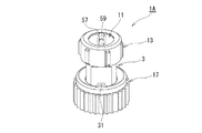
以下、本発明の第1実施形態に係る噴霧ノズルの構成を図1〜図5に基づいて詳細に説明する。
本発明の第1実施形態に係る噴霧ノズル1Aは、薬液と空気とを混合した混合流体を所定の範囲に散布するものである。
図4に示すように、噴霧ノズル1Aは、ノズルホルダ3と、整流中子5と、オリフィス板7と、オリフィス中子9と、先噴板11と、ノズルキャップ13と、Oリング15と、連結具17と、を備えている。
Hereinafter, the configuration of the spray nozzle according to the first embodiment of the present invention will be described in detail with reference to FIGS. 1 to 5.
The
As shown in FIG. 4, the
ノズルホルダ3は、略円筒状をなしており、基端側が連結具17(後述参照)を介して供給管19に連結されている。このノズルホルダ3は、先端側の外周部にノズルキャップ13の雌ねじ部63(後述参照)と螺合する雄ねじ部21(図3及び図4参照)が形成され、また、先端側の端面に平面視略円形状の凹部23が形成されている。更に、ノズルホルダ3の基端側には、その外周部から径方向外側に広がるフランジ部25が形成されている。また、図4に示されているように、ノズルホルダ3は、混合室27と、流路29と、導入路31と、位置決め穴33(位置決め部)と、大径部35と、を備えている。混合室27は、薬液と空気とを混合させる場所であり、ノズルホルダ3の基端側に形成されている。この混合室27は、円筒部27aと、下流側に向かって縮径した縮径部27bとからなり、少なくとも円筒部27a内で薬液と空気とを混合させる。流路29は、混合室27の縮径部27bに連通しており、混合室27からノズルホルダ3の先端側に向かって軸方向に延びている。導入路31は、ノズルホルダ3の基端側の外壁部を貫通して、混合室27の円筒部27aに連通するように複数形成されている(本実施形態では2つ)。この導入路31は、オリフィス板7のピンホール49(すなわち、オリフィス板の頂、後述参照)より下流側に位置するものである。位置決め穴33は、平面視略円形状であり、ノズルホルダ3の凹部23の底面に複数形成され(本実施形態では2つ)、凹部23の底面から基端側に向かって軸方向に延びて(混合室27には至らない)形成されている。また、この位置決め穴33は、整流中子5の一対の第1の位置決め突起部45,45(後述参照)を挿入可能な深さ、かつ、嵌合可能な直径で形成されている。大径部35は、混合室27より上流側に形成されており、この大径部35にオリフィス板7及びオリフィス中子9が収納されている。
The
整流中子5は、略平板状をなしており、噴霧ノズル1Aの下流側に設けられ、具体的には、ノズルホルダ3の先端側の端面上に配置されている(図3参照)。この整流中子5は、案内流路37を備え、下流側の表面に整流突起部39及び一対の第1の位置決め突起部41,41が形成され、上流側の表面に隆起部43及び一対の第2の位置決め突起部45,45(位置決め部)が形成されている。案内流路37は、ノズルホルダ3の流路29を流れる混合流体を先噴板11のスリット59(後述参照)に案内するものであり、複数形成されている(本実施形態では2つ)。整流突起部39は、正面視山形状、すなわち、先噴板11のスリット59に向けて先端幅が縮小する突起部である(図3(a)及び図4参照)。この整流突起部39は、上流側の表面の略中央に配置され、整流突起部39の壁面が複数の案内流路37を構成する壁面の下流側に配置されている。一対の第1の位置決め突起部41,41は、先噴板11の筋状絞り部57(後述参照)に向けて延び、平面視で案内流路37及び整流突起部39と直列になるように配置されている(図4参照)。隆起部43は、ノズルホルダ3の流路29に対向するように、略中央からノズルホルダ3の凹部23内に向かって延びており、案内流路37,37との間に配置されている。一対の第2の位置決め突起部45,45は、略円柱状であり、複数形成され(本実施形態では2つ)、整流中子5の上流側の表面からノズルホルダ3の軸方向に沿って延びている。
The rectifying
オリフィス板7は、ドーム状をなしており、ノズルホルダ3の上流側、具体的には、混合室27の円筒部27aと導入路31との合流位置よりも上流側に位置し、ノズルホルダ3の大径部35に設けられている(図3参照)。このオリフィス板7は、ドーム状絞り部47を備え、このドーム状絞り部47の頂部には、上流側から薬液を受けて混合室27に薬液を供給するピンホール49が形成されている。このピンホール49は、本例では径が0.3mmに形成されている。なお、ピンホール径は、適宜変更することができる。
The
オリフィス中子9は、略円板状をなしており、オリフィス板7よりもノズルホルダ3の流路29の上流側に位置し、ノズルホルダ3の大径部35に設けられている(図3参照)。このオリフィス中子9は、外周面に薬液流路51及び第1突起部53(図3(b)参照)が形成され、上流側の表面に第2突起部55が形成されている。薬液流路51は、ノズルホルダ3の流路29の延長方向軸に対して傾斜するよう形成され(図3(b)及び図4参照)、周方向に180°間隔を置いて設けられている。第1突起部53は、外周の一部から径方向外側に向けて延びており(図3(b)参照)、オリフィス中子9をノズルホルダ3の大径部35に装着した後、オリフィス中子9が大径部35から脱落を防止するためのものである。第2突起部55には、オリフィス中子9を取外す際に、使用者が指を引掛けるための引掛け部55aが形成されている。
The
先噴板11は、略円板であり、ノズルホルダ3の先端側に配置されている。この先噴板11は、筋状絞り部57と、スリット59と、を備えている。筋状絞り部57は、下流側に向けて筋状に突出し、整流中子5の一対の第1の位置決め突起部41,41と係合する係合部57aが形成されている。スリット59は、筋状絞り部57の長手方向の略中央において、筋状絞り部57を横切るようにして、筋状絞り部57の延長方向と直交する方向に少なくとも筋状絞り部57の頂点部分を分断する態様で形成されている。
The
ノズルキャップ13は、略円筒状をなしており、ノズルホルダ3の先端に先噴板11を保持するものである。このノズルキャップ13には、ノズルホルダ3の流路29を流れる混合流体の圧力によって、先噴板11がノズルキャップ3から抜けないように、先端側の内周部から径方向内側に延びる環状の突起部61が形成されている(図3参照)。また、ノズルキャップ13の内周部には、ノズルホルダ3の雄ねじ部21に螺合する雌ねじ部63が形成されている(図3及び図4参照)。また、ノズルホルダ3の先端側の端面と先噴板11との間に、かつ、整流中子5の外周部を取り囲むようにしてOリング15が配置され、このOリング15により、ノズルホルダ3と先噴板11との間の液漏れを防いでいる。
The
連結具17は、略円筒状をなしており、これによって、ノズルホルダ3と供給管19とが連結される。この連結具17には、供給管19を流れる薬液の圧力によって、ノズルホルダ3が連結具17から抜けることのないように、先端側の内周部から径方向内側に延びて、ノズルホルダ3のフランジ部25に当接する環状の突起部65が形成されている(図3参照)。また、連結具17の内周部には、供給管19の雄ねじ部68に螺合する雌ねじ部69が形成されている。薬液タンク等(図示省略)から供給される薬液は、供給管19を介して、ノズルホルダ3の流路29に供給されるものであり、この供給管19とノズルホルダ3との連結部には、薬液内に固形物が混入した場合に、それをろ過するフィルタ67が設けられている。
The
次に、本発明の第1実施形態に係る噴霧ノズル1Aにおける薬液及び混合流体の流れについて、以下に説明する。
まず、薬液タンク等から供給され、供給管19を流れる薬液は、フィルタ67を通過した後、ノズルホルダ3の大径部35に向かって流込む(図3(a)及び(b)の矢印a参照)。続いて、薬液は、オリフィス中子9の薬液流路51を通過して、オリフィス板7のドーム絞り部47内へと流れる(図3(a)及び(b)の矢印b参照)。このとき、薬液は、薬液流路51を通過することで、旋回流となって、ドーム絞り部47内に流込む(図3(a)及び(b)の矢印c参照)。そして、薬液がオリフィス板7のピンホール49を通過し、混合室27の円筒部27a内に流込む。この際、薬液は、導入路31から導入された空気と混合されながら、流路29に流れて行く(図3(a)及び(b)の矢印d参照)。しかも、ピンホール49を通過した薬液は、旋回流を維持しながら円筒部47内に流込むため、導入路31から円筒部27aへと導入される空気の流れが安定し、噴霧ノズル1Aから噴霧される泡状粒子の粒子径やその噴霧パターンの安定化に寄与するものとなる。そして、流路29を流れる混合流体は、続いて整流中子5の案内流路37,37を通過する(図3(a)の矢印e参照)。このとき、混合流体が整流中子5の隆起部43に衝突することで、混合流体の流れ方向が変化し、案内流路37,37へと導かれる。そして、案内流路37,37を流れる混合流体は、整流突起部39と先噴板11の筋状絞り部57との間隙を通過し(図3(a)の矢印f参照)、スリット59を介して外部に噴霧される(図3(a)及び(b)の矢印g参照)。なお、先噴板11のスリット59から噴霧された混合流体の噴霧パターンは、本実施形態では、噴霧ノズル1Aの正面視で約100°の角度からなる扇状乃至扇面状に噴霧される(図5参照)。
Next, the flow of the chemical solution and the mixed fluid in the
First, the chemical solution supplied from the chemical solution tank or the like and flowing through the
さて、上記構成を有する第1実施形態の噴霧ノズル1Aによれば、次のような作用効果を得ることができる。すなわち、噴霧ノズル1Aの先端側においては、先噴板11とノズルホルダ3との間に、配置された整流中子5に先噴板11のスリット59へと案内する複数の案内流路37,37が形成されていることから、この複数の案内路37,37を介して、ノズルホルダ3の流路29を流れる混合流体が先噴板11のスリット59に向かって案内される。また、噴霧ノズル1Aは、先噴板11に下流側に向けて筋状に突出する筋状絞り部57が形成され、この筋状絞り部57にスリット59が形成されていることで、整流中子5の複数の案内流路37,37を流れる混合流体は、筋状絞り部57に集まり、スリット59を介して、噴霧ノズル1Aの外部へと噴霧されることとなる。
By the way, according to the
噴霧ノズル1Aにおいて、整流中子5には、筋状絞り部57に形成されたスリット59に向けて先端幅が縮小する整流突起部39が形成されていることから、整流中子5の複数の案内流路37,37を通過してスリット59に向かう混合流体は、複数の案内流路37,37を構成する壁面の下流側に配置された、整流突起部39を構成する壁面に沿って案内され、筋状絞り部57に向けて円滑に流れて行くことが可能となる。更に、スリット59を通過した混合流体は、粒子径のばらつきが少ない、すなわち、ドリフトの影響を受け易い過剰に微細な噴霧粒子の割合や、拡散し難い過剰に粒子径の大きな噴霧粒子の割合が少なく、噴霧に適した粒子径を大部分とする噴霧粒子となって、噴霧ノズル1Aの外部へと噴霧される。これにより、噴霧ノズル1Aを除草剤の噴霧に用いる場合には、風などの気象条件の影響を受けることなく、広範囲に適量の除草剤を噴霧して、除草効果を高めることが可能となる。
In the
更に、噴霧ノズル1Aの基端部においては、混合室27の円筒部27aと導入路31との合流位置よりも流路29の上流側に配置されたオリフィス板7に、ピンホール49が形成されていることから、オリフィス板7の上流側の薬液は、ピンホール49を介して混合室27の円筒部27a内に供給される。また、薬液は、オリフィス板7よりも流路の上流側に位置するオリフィス中子9の薬液流路51,51を介してオリフィス板7へと供給され、オリフィス板7に形成された下流側へ向けてドーム状に突出するドーム状絞り部47のドームの頂に薬液が集まる。これのより、ドーム状絞り部47の頂部に形成されたピンホール49からノズルホルダ3の混合室27の円筒部27aに向かって円滑に流込むこととなる。このため、導入路31から円筒部27aへと導入される空気の流入状態が、円筒部27a内の薬液の流れの乱れによって阻害されることなく安定する。よって、円筒部27aに流入した薬液と空気とが一定の割合で混合され、混合流体は、混合室27の下流の流路29へと送り込まれることとなる。このように、混合室27において、薬液と空気との割合が安定した混合流体を作り出すことで、最終的に先噴板11のスリット59から、泡状粒子の態様で噴霧ノズル1Aの外部へと噴霧される混合流体の、粒子径やその噴霧パターンの安定化に寄与するものとなる。
Further, at the base end portion of the
また、噴霧ノズル1Aにおいて、オリフィス中子9の薬液流路51,51がノズルホルダ3の流路29の延長方向軸に対して傾斜するように形成されていることで、薬液流路51,51を通った薬液は、薬液流路通過前の流れ状態の如何にかかわらず、薬液流路によって流れ方向が矯正され、オリフィス中子9の下流側で旋回流となる。この旋回流は、オリフィス板7のドーム状絞り部47のドーム内でも維持され、オリフィス板7のピンホール49から混合室27へと流れる薬液の流れが整流されることで、上述のごとく、混合室27の円筒部27aにおける薬液と空気との混合状態を安定させることが可能となる。
Further, in the
また、噴霧ノズル1Aにおいて、整流中子5は、整流突起部39の係合面が筋状絞り部57の凹面と係合し、なおかつ、筋状絞り部57の凹面と係合する一対の第1の位置決め突起部41,41を整流中子5と離間した位置に備えていることから、一対の第1の位置決め突起部41,41と筋状絞り部57の凹面との係合により、複数の位置で、整流中子5と先噴板11との位置決めが行われることが可能となる。これにより、筋状絞り部57に形成されたスリット59と、整流中子5に形成された整流突起部39との位置合わせが高精度になされ、上述の作用効果がより安定確実に得られるものとなる。
Further, in the
また、噴霧ノズル1Aにおいて、ノズルホルダ3に複数の位置決め穴33,33を形成し、整流中子5に一対の第2の位置決め突起部45,45を形成することで、ノズルホルダ3と整流中子5との位置ずれを防ぎ、また、整流中子5がノズルホルダ3からの脱落を防ぐことが可能となる。
Further, in the
次に、本発明の第2実施形態の噴霧ノズル1Bについて、図6〜図9を参照して説明する。なお、以下の説明において、上記第1実施形態の噴霧ノズル1Aに対して、同様の部分には同じ参照符号を用いて、異なる部分についてのみ詳細に説明する。
Next, the
図7及び図8に示すように、第2実施形態の噴霧ノズル1Bは、混合流体を二方向に噴霧するものであり、第1実施形態に係るノズルホルダ3の代わりに、第1ノズルホルダ71(ノズルホルダ)と、第2ノズルホルダ73と、を備えている。第1ノズルホルダ71は、第2ノズルホルダ73にいわゆるムリバメ、すなわち、第1ノズルホルダ71の先端側を第2ノズルホルダ73の接続部77(後述参照)の内周部に圧入した際、第1ノズルホルダ71の第1環状係止部74(後述参照)が第2ノズルホルダ73の第2環状係止部76(後述参照)によって弾性変形し、第1ノズルホルダ71が所定の位置まで圧入されることで、第1環状係止部74の形状が弾性復帰して、第1環状係止部74と第2環状係止部76とが係合し、第2ノズルホルダ73に連結される(図7参照)。第1ノズルホルダ71の先端側の外周部には、円錐台状をなして、基端側に向かうにしたがい径方向外側に突出する第1環状係止部74が形成されている。また、第1ノズルホルダ71は、流路72と、空気の導入路31と、オリフィス板7及びオリフィス中子9を収納する大径部35と、オリフィス板7のドーム状絞り部47を収納する収納部75と、を備えている。導入路31は、第1ノズルホルダ71の外壁部から上流側の流路72と収納部75との連続位置に向かって開口するように、形成されている。第2ノズルホルダ73は、第1ノズルホルダ71の先端側の外周部に接続される接続部77と、この接続部77から二股に分岐して形成された第1分岐流路81及び第2分岐流路83を有する分岐部79と、を備えている。接続部77の内周部には、第1環状係止部74のムリバメ時に第1環状係止部74の弾性変形を促すと共に、ムリバメ完了時に、第1環状係止部74に係合するための、径方向内側に帯状に一定径で突出する第2環状係止部76(図7参照)が形成されている。また、接続部77の内周部には、第1環状係止部74を収容するための、第1環状係止部74と相補的な形状を有するテーパ部80(図7参照)が形成されている。分岐部79の下流側先端の外周部には、ノズルキャップ13の雌ねじ部63と螺合する雄ねじ部78が形成されており、分岐部79の下流側先端に整流中子5、先噴板11、ノズルキャップ13及びOリング15が装着されている。分岐部79の第1分岐流路81及び第2分岐流路83は、所定の角度で分岐し、それぞれが第1ノズルホルダ71の流路72に連通されている。
As shown in FIGS. 7 and 8, the
次に、本発明の第2実施形態に係る噴霧ノズル1Bにおける薬液及び混合流体の流れについて、以下に説明する。
薬液タンク等から供給され、供給路19を流れる薬液は、第1実施形態と同様に、オリフィス中子9の薬液流路51及びオリフィス板7のピンホール49を通り(図7の矢印a及びb参照)、ピンホール49を通過した薬液は、旋回状態を維持しながら(図7の矢印c参照)、上流側の流路72と収納部75との連通位置で、導入路31から導入された空気と混同される。そして、薬液と空気が混合された混合流体は、流路72及び第2ノズルホルダ73の第1分岐流路81及び第2分岐流路83に、各々分岐して流入する(図7の矢印d及びe参照)。そして、第1分岐流路81及び第2分岐流路83を各々流れる混合流体は、第1実施形態と同様に、案内流路37,37及び整流突起部39と筋状絞り部57との間隙を通って(図3(a)の矢印e及びf参照)、スリット59から外部に噴霧される(図7の矢印f参照)。第1分岐流路81及び第2分岐流路83を流れる混合流体が、先噴板11のスリット59から噴霧されたときの噴霧パターンは、図9に示されているように、噴霧ノズル1Bの正面視で各々約50°の角度からなる扇状乃至扇面状に噴霧され、全体で約95°の角度からなる扇状乃至扇面状に噴霧される。
Next, the flow of the chemical solution and the mixed fluid in the
The chemical solution supplied from the chemical solution tank or the like and flowing through the
以上、第2実施形態の噴霧ノズル1Bによれば、以下のような作用効果を奏するものとなる。
すなわち、第2実施形態では、第2ノズルホルダ73が二股に分岐して形成されているため、第1ノズルホルダ71の流路72を流れる混合流体は、第1分岐流路81及び第2分岐流路83の各々に分岐されて、第1分岐流路81及び第2分岐流路83の各々を通過し、先噴板11,11のスリット59,59から互いに異なる方向へと同時に散布することが可能となる。更に、噴霧ノズル1Bは、第1ノズルホルダ71の上流側にオリフィス板7及びオリフィス中子9を配備し、第2ノズルホルダ83の下流側先端に整流中子5、先噴板11、ノズルキャップ13及びOリング15を装着していることから、第1分岐流路81及び第2分岐流路83の各々おいて、上記第1実施形態と同様の作用効果を得ることが可能となる。
As described above, according to the
That is, in the second embodiment, since the
なお、第1及び第2実施形態に係る噴霧ノズル1A,1Bは、オリフィス中子9の薬液流路51がノズルホルダ3又は第1ノズルホルダ71の流路29,72の延長方向軸に対して傾斜するよう2つ形成されているが、1つ又は3つ等の流路の数を変更してもよい。また、薬液流路51,51がオリフィス中子9の外周面に斜め溝として形成されているが、オリフィス中子9の、外周面より内側の部分において、上流側の表面から下流側の表面に斜めに貫通するように形成してもよい。
In the
更に、第1及び第2実施形態に係る噴霧ノズル1A,1Bでは、薬液流路51,51が斜め溝であるが、薬液流路51,51の位置とオリフィス板7のドーム状絞り部47のドーム形状との相互関係によって、ドーム絞り部47の薬液の流れが適切に整流され、オリフィス板7のピンホール49を通過する薬液と空気との割合が安定した混合流体を作り出すことが得られるような場合には、この薬液流路51,51をノズルホルダ3又は第1ノズルホルダ71の軸方向に延びる、1つ或いは複数の孔としてもよい。また、斜め溝の薬液流路51,51と、ノズルホルダ3又は第1ノズルホルダ71の軸方向に延びる薬液流路51,51と、をオリフィス中子9に形成してもよい。
Further, in the
1A,1B…噴霧ノズル、3…ノズルホルダ、5…整流中子、7…オリフィス板、9…オリフィス中子、27…混合室、29…流路、37…案内流路、39…整流突起部、47…ドーム状絞り部、49…ピンホール、51…薬液流路、57…筋状絞り部、59…スリット 1A, 1B ... spray nozzle, 3 ... nozzle holder, 5 ... rectifying core, 7 ... orifice plate, 9 ... orifice core, 27 ... mixing chamber, 29 ... flow path, 37 ... guide flow path, 39 ... rectifying protrusion , 47 ... Dome-shaped diaphragm, 49 ... Pinhole, 51 ... Chemical flow path, 57 ... Streaks, 59 ... Slit
Claims (6)
基端側に配置され、前記薬液と前記空気とが混合する混合室と、該混合室から先端側に延びる流路と、前記混合室内に外部から空気を導入する導入路とが形成されたノズルホルダと、
前記ノズルホルダの先端側に配置され、前記流路から前記混合流体を受けて、前記混合流体を噴射するスリットが形成された先噴板と、
前記ノズルホルダの先端に前記先噴板を保持するノズルキャップと、
前記先噴板と前記ノズルホルダとの間に配置され、前記流路から前記混合流体を受けて、前記混合流体を前記先噴板の前記スリットへと案内する複数の案内流路が形成された整流中子と、
前記混合室の前記流路と前記導入路との合流位置よりも前記流路の上流側に配置され、かつ、上流側から前記薬液を受けて前記混合室に前記薬液を供給するピンホールが形成されたオリフィス板と、
前記オリフィス板よりも前記流路の上流側に設けられ、前記オリフィス板と前記ノズルホルダと連結される連結具に設けられるフィルタとの間に配置され、前記薬液が流れる薬液流路が形成されたオリフィス中子と、を備え、
前記先噴板には、下流側に向けて筋状に突出する筋状絞り部が形成され、該筋状絞り部を横切る態様で前記スリットが形成されており、
前記整流中子には、前記先噴板の前記スリットに向けて先端幅が縮小する態様で整流突起部が形成され、かつ、該整流突起部を構成する壁面が前記複数の案内流路を構成する壁面の下流側に配置されており、
前記オリフィス板には、下流側へ向けてドーム状に突出するドーム状絞り部が形成され、該ドーム状絞り部の頂部に前記ピンホールが形成されていることを特徴とする噴霧ノズル。 A spray nozzle that sprays a mixed fluid that is a mixture of chemicals and air in the form of a mist.
A nozzle arranged on the base end side and formed with a mixing chamber in which the chemical solution and the air are mixed, a flow path extending from the mixing chamber to the tip side, and an introduction path for introducing air into the mixing chamber from the outside. With the holder
A front injection plate arranged on the tip end side of the nozzle holder and formed with a slit for receiving the mixed fluid from the flow path and injecting the mixed fluid.
A nozzle cap that holds the tip jet plate at the tip of the nozzle holder,
A plurality of guide flow paths are formed which are arranged between the front injection plate and the nozzle holder, receive the mixed fluid from the flow path, and guide the mixed fluid to the slit of the front injection plate. With the rectifying core,
A pinhole is formed which is arranged on the upstream side of the flow path from the confluence position of the flow path and the introduction path of the mixing chamber and receives the chemical solution from the upstream side and supplies the chemical solution to the mixing chamber. Orifice plate and
A chemical liquid flow path is formed which is provided on the upstream side of the flow path with respect to the orifice plate and is arranged between the orifice plate and a filter provided in a connector connected to the nozzle holder to allow the chemical liquid to flow. With an orifice core,
The front jet plate is formed with a streak-shaped throttle portion that protrudes in a streak shape toward the downstream side, and the slit is formed so as to cross the streak-shaped throttle portion.
The rectifying core is formed with a rectifying protrusion in a manner in which the tip width is reduced toward the slit of the front injection plate, and the wall surface constituting the rectifying protrusion constitutes the plurality of guide flow paths. It is located on the downstream side of the wall surface
A spray nozzle characterized in that a dome-shaped throttle portion is formed on the orifice plate so as to project in a dome shape toward the downstream side, and the pinhole is formed at the top of the dome-shaped throttle portion.
前記整流中子は、前記整流突起部と直列になるように配置され、前記筋状絞り部の凹面と係合する位置決め突起部を備えていることを特徴とする請求項1乃至4のいずれか1項に記載の噴霧ノズル。 The rectifying protrusion of the rectifying core has an engaging surface with the concave surface of the streak drawing portion of the tip injection plate.
Any one of claims 1 to 4, wherein the rectifying core is arranged so as to be in series with the rectifying protrusion, and includes a positioning protrusion that engages with the concave surface of the streak drawing portion. The spray nozzle according to item 1.
Priority Applications (1)
| Application Number | Priority Date | Filing Date | Title |
|---|---|---|---|
| JP2017148089A JP6877288B2 (en) | 2017-07-31 | 2017-07-31 | Spray nozzle |
Applications Claiming Priority (1)
| Application Number | Priority Date | Filing Date | Title |
|---|---|---|---|
| JP2017148089A JP6877288B2 (en) | 2017-07-31 | 2017-07-31 | Spray nozzle |
Publications (2)
| Publication Number | Publication Date |
|---|---|
| JP2019025432A JP2019025432A (en) | 2019-02-21 |
| JP6877288B2 true JP6877288B2 (en) | 2021-05-26 |
Family
ID=65477116
Family Applications (1)
| Application Number | Title | Priority Date | Filing Date |
|---|---|---|---|
| JP2017148089A Active JP6877288B2 (en) | 2017-07-31 | 2017-07-31 | Spray nozzle |
Country Status (1)
| Country | Link |
|---|---|
| JP (1) | JP6877288B2 (en) |
Families Citing this family (4)
| Publication number | Priority date | Publication date | Assignee | Title |
|---|---|---|---|---|
| JP2022014191A (en) * | 2020-07-06 | 2022-01-19 | 株式会社麻場 | Spray nozzle |
| JP2022014193A (en) * | 2020-07-06 | 2022-01-19 | 株式会社麻場 | Spray nozzle |
| JP7453688B2 (en) * | 2021-09-17 | 2024-03-21 | ヤマホ工業株式会社 | spray nozzle |
| JP2023179262A (en) * | 2022-06-07 | 2023-12-19 | 株式会社麻場 | spray nozzle |
Family Cites Families (7)
| Publication number | Priority date | Publication date | Assignee | Title |
|---|---|---|---|---|
| JPS5843958Y2 (en) * | 1980-08-04 | 1983-10-05 | 株式会社 丸山製作所 | Foam nozzle |
| JPS60155961U (en) * | 1984-03-26 | 1985-10-17 | ヤマホ工業株式会社 | pesticide spray nozzle |
| DE4338585A1 (en) * | 1993-11-11 | 1995-05-18 | Graef Jordt Steffen | Injector nozzle |
| JP4397608B2 (en) * | 2003-03-18 | 2010-01-13 | 独立行政法人農業・食品産業技術総合研究機構 | Spray nozzle |
| JP4523484B2 (en) * | 2005-05-23 | 2010-08-11 | 株式会社丸山製作所 | Spray nozzle |
| JP5096773B2 (en) * | 2007-03-27 | 2012-12-12 | 独立行政法人農業・食品産業技術総合研究機構 | Liquid spray method and traveling spray apparatus using two-way injection nozzle |
| JP5530974B2 (en) * | 2011-05-18 | 2014-06-25 | ヤマホ工業株式会社 | Spray nozzle dedicated to aeration type |
-
2017
- 2017-07-31 JP JP2017148089A patent/JP6877288B2/en active Active
Also Published As
| Publication number | Publication date |
|---|---|
| JP2019025432A (en) | 2019-02-21 |
Similar Documents
| Publication | Publication Date | Title |
|---|---|---|
| CN105008054B (en) | Atomizer for sanitary outlet device and the sanitary outlet fitting with discharging device | |
| JP5788805B2 (en) | Spray nozzles and aerosol products | |
| JP6478105B2 (en) | Two-fluid nozzle | |
| JP6033773B2 (en) | Static spray mixer | |
| US6561438B1 (en) | Foam generating nozzle assembly | |
| CN108348933B (en) | Nozzle and method of mixing fluid streams | |
| TWI586439B (en) | Static spray mixing device | |
| KR101855211B1 (en) | Nozzle for swirling air of vinyl house | |
| JP2019025432A (en) | Spray nozzle | |
| CN102161023A (en) | Shower apparatus | |
| USRE30004E (en) | Low drift spray nozzle | |
| RU2434686C2 (en) | Fluid sprayer and sprayer head (versions) | |
| RU2647104C2 (en) | Finely divided liquid sprayer | |
| RU2615256C1 (en) | Fine-dispersed liquid sprayer | |
| JP2020163255A (en) | Sprayer | |
| JP2018058063A (en) | Nozzle hole part structure of spray mechanism | |
| RU2437724C2 (en) | Liquid sprayer nozzle (versions) | |
| US10272456B2 (en) | Spraying apparatus | |
| TWM548027U (en) | Agricultural weeding throttle spray head and spray device | |
| JP6775617B2 (en) | Spray nozzle cover | |
| KR20200029798A (en) | injection devices for fluid | |
| RU2577653C1 (en) | Kochetov centrifugal vortex burner | |
| RU2456041C1 (en) | Sprayer | |
| KR102412969B1 (en) | A fine spray nozzle with a simple structure and a disinfection device having the same | |
| RU2551733C1 (en) | Kochetov's fluid fine sprayer |
Legal Events
| Date | Code | Title | Description |
|---|---|---|---|
| A621 | Written request for application examination |
Free format text: JAPANESE INTERMEDIATE CODE: A621 Effective date: 20191125 |
|
| A977 | Report on retrieval |
Free format text: JAPANESE INTERMEDIATE CODE: A971007 Effective date: 20200910 |
|
| A131 | Notification of reasons for refusal |
Free format text: JAPANESE INTERMEDIATE CODE: A131 Effective date: 20200923 |
|
| A521 | Request for written amendment filed |
Free format text: JAPANESE INTERMEDIATE CODE: A523 Effective date: 20201118 |
|
| TRDD | Decision of grant or rejection written | ||
| A01 | Written decision to grant a patent or to grant a registration (utility model) |
Free format text: JAPANESE INTERMEDIATE CODE: A01 Effective date: 20210421 |
|
| A61 | First payment of annual fees (during grant procedure) |
Free format text: JAPANESE INTERMEDIATE CODE: A61 Effective date: 20210427 |
|
| R150 | Certificate of patent or registration of utility model |
Ref document number: 6877288 Country of ref document: JP Free format text: JAPANESE INTERMEDIATE CODE Ref document number: 6877288 Country of ref document: JP Free format text: JAPANESE INTERMEDIATE CODE: R150 |
|
| R250 | Receipt of annual fees |
Free format text: JAPANESE INTERMEDIATE CODE: R250 |
|
| R250 | Receipt of annual fees |
Free format text: JAPANESE INTERMEDIATE CODE: R250 |
|
| R250 | Receipt of annual fees |
Free format text: JAPANESE INTERMEDIATE CODE: R250 |