JP6885802B2 - Secondary battery - Google Patents
Secondary battery Download PDFInfo
- Publication number
- JP6885802B2 JP6885802B2 JP2017124036A JP2017124036A JP6885802B2 JP 6885802 B2 JP6885802 B2 JP 6885802B2 JP 2017124036 A JP2017124036 A JP 2017124036A JP 2017124036 A JP2017124036 A JP 2017124036A JP 6885802 B2 JP6885802 B2 JP 6885802B2
- Authority
- JP
- Japan
- Prior art keywords
- secondary battery
- positive electrode
- region
- active material
- lithium
- Prior art date
- Legal status (The legal status is an assumption and is not a legal conclusion. Google has not performed a legal analysis and makes no representation as to the accuracy of the status listed.)
- Active
Links
Images





Classifications
-
- Y—GENERAL TAGGING OF NEW TECHNOLOGICAL DEVELOPMENTS; GENERAL TAGGING OF CROSS-SECTIONAL TECHNOLOGIES SPANNING OVER SEVERAL SECTIONS OF THE IPC; TECHNICAL SUBJECTS COVERED BY FORMER USPC CROSS-REFERENCE ART COLLECTIONS [XRACs] AND DIGESTS
- Y02—TECHNOLOGIES OR APPLICATIONS FOR MITIGATION OR ADAPTATION AGAINST CLIMATE CHANGE
- Y02E—REDUCTION OF GREENHOUSE GAS [GHG] EMISSIONS, RELATED TO ENERGY GENERATION, TRANSMISSION OR DISTRIBUTION
- Y02E60/00—Enabling technologies; Technologies with a potential or indirect contribution to GHG emissions mitigation
- Y02E60/10—Energy storage using batteries
-
- Y—GENERAL TAGGING OF NEW TECHNOLOGICAL DEVELOPMENTS; GENERAL TAGGING OF CROSS-SECTIONAL TECHNOLOGIES SPANNING OVER SEVERAL SECTIONS OF THE IPC; TECHNICAL SUBJECTS COVERED BY FORMER USPC CROSS-REFERENCE ART COLLECTIONS [XRACs] AND DIGESTS
- Y02—TECHNOLOGIES OR APPLICATIONS FOR MITIGATION OR ADAPTATION AGAINST CLIMATE CHANGE
- Y02P—CLIMATE CHANGE MITIGATION TECHNOLOGIES IN THE PRODUCTION OR PROCESSING OF GOODS
- Y02P70/00—Climate change mitigation technologies in the production process for final industrial or consumer products
- Y02P70/50—Manufacturing or production processes characterised by the final manufactured product
Landscapes
- Battery Electrode And Active Subsutance (AREA)
- Electric Double-Layer Capacitors Or The Like (AREA)
- Carbon And Carbon Compounds (AREA)
Description
本発明の一様態は、物、方法、又は、製造方法に関する。または、本発明は、プロセス、マシン、マニュファクチャ、又は、組成物(コンポジション・オブ・マター)に関する。本発明の一態様は、半導体装置、表示装置、発光装置、蓄電装置、照明装置または電子機器、またはそれらの製造方法に関する。特に、二次電池に用いることのできる正極活物質、二次電池、および二次電池を有する電子機器に関する。 The homogeneity of the present invention relates to a product, a method, or a manufacturing method. Alternatively, the present invention relates to a process, machine, manufacture, or composition (composition of matter). One aspect of the present invention relates to a semiconductor device, a display device, a light emitting device, a power storage device, a lighting device or an electronic device, or a method for manufacturing the same. In particular, the present invention relates to a positive electrode active material that can be used for a secondary battery, a secondary battery, and an electronic device having the secondary battery.
なお、本明細書中において、蓄電装置とは、蓄電機能を有する素子及び装置全般を指すものである。例えば、リチウムイオン二次電池などの蓄電池(二次電池ともいう)、リチウムイオンキャパシタ、及び電気二重層キャパシタなどを含む。 In addition, in this specification, a power storage device refers to an element having a power storage function and a device in general. For example, it includes a storage battery (also referred to as a secondary battery) such as a lithium ion secondary battery, a lithium ion capacitor, an electric double layer capacitor, and the like.
また、本明細書中において電子機器とは、蓄電装置を有する装置全般を指し、蓄電装置を有する電気光学装置、蓄電装置を有する情報端末装置などは全て電子機器である。 Further, in the present specification, the electronic device refers to all devices having a power storage device, and an electro-optical device having a power storage device, an information terminal device having a power storage device, and the like are all electronic devices.
近年、リチウムイオン二次電池、リチウムイオンキャパシタ、空気電池等、種々の蓄電装置の開発が盛んに行われている。特に高出力、高エネルギー密度であるリチウムイオン二次電池は、携帯電話、スマートフォン、タブレット、もしくはノート型コンピュータ等の携帯情報端末、携帯音楽プレーヤ、デジタルカメラ、医療機器、又は、ハイブリッド車(HEV)、電気自動車(EV)、もしくはプラグインハイブリッド車(PHEV)等の次世代クリーンエネルギー自動車など、半導体産業の発展と併せて急速にその需要が拡大し、充電可能なエネルギーの供給源として現代の情報化社会に不可欠なものとなっている。 In recent years, various power storage devices such as lithium ion secondary batteries, lithium ion capacitors, and air batteries have been actively developed. Lithium-ion secondary batteries, which have particularly high output and high energy density, are mobile information terminals such as mobile phones, smartphones, tablets, or notebook computers, portable music players, digital cameras, medical devices, or hybrid vehicles (HEVs). Demand for next-generation clean energy vehicles such as electric vehicles (EVs) or plug-in hybrid vehicles (PHEVs) is expanding rapidly with the development of the semiconductor industry, and modern information is available as a source of rechargeable energy. It has become indispensable to the computerized society.
リチウムイオン二次電池に要求されている特性としては、さらなる高エネルギー密度化、サイクル特性の向上及び様々な動作環境での安全性、長期信頼性の向上などがある。 The characteristics required for a lithium-ion secondary battery include further increase in energy density, improvement in cycle characteristics, safety in various operating environments, and improvement in long-term reliability.
そこでリチウムイオン二次電池のサイクル特性の向上および高容量化を目指した、正極活物質の改良が検討されている。(特許文献1および特許文献2)
Therefore, improvement of the positive electrode active material is being studied with the aim of improving the cycle characteristics and increasing the capacity of the lithium ion secondary battery. (
リチウムイオン二次電池およびそれに用いられる正極活物質層には、充放電特性、サイクル特性、信頼性、安全性、又はコストといった様々な面で改善の余地が残されている。 The lithium ion secondary battery and the positive electrode active material layer used therein have room for improvement in various aspects such as charge / discharge characteristics, cycle characteristics, reliability, safety, or cost.
リチウムイオン二次電池は、正極板の単位体積あたりの放電容量(体積容量密度とも言える)をさらに高める、高エネルギー密度化が求められている。高エネルギー密度のリチウムイオン二次電池を得るための正極に対して、高い電極密度が要求されている。また、正極活物質の平均粒径が大きい場合に、高い電極密度が得られる。さらに、高い電極密度とするためにはプレス加工を行えばよい。高い電極密度は、活物質のタップ密度や圧縮密度が指標とされ、特に圧縮密度は電極密度との相関が高い。本明細書において真密度とは、物体の表面や内部の気孔の部分を除いた物体そのものの体積で質量を割った値であり、タップ密度とは粉体を容器につめ、振動させ、充填させて測定した嵩密度であり、真密度以下となる場合がある。 Lithium-ion secondary batteries are required to have a high energy density that further increases the discharge capacity (which can be said to be the volume capacity density) per unit volume of the positive electrode plate. A high electrode density is required for a positive electrode for obtaining a lithium ion secondary battery having a high energy density. Further, when the average particle size of the positive electrode active material is large, a high electrode density can be obtained. Further, in order to obtain a high electrode density, press working may be performed. The high electrode density is indexed by the tap density and compression density of the active material, and the compression density is particularly highly correlated with the electrode density. In the present specification, the true density is a value obtained by dividing the mass by the volume of the object itself excluding the surface of the object and the pores inside, and the tap density is a value obtained by filling a container with powder, vibrating it, and filling it. It is the bulk density measured in the above, and may be less than the true density.
一方、プレスによって電極密度を高くすると、充放電サイクルにおける電池容量が低下しやすい傾向があった。 On the other hand, when the electrode density is increased by pressing, the battery capacity in the charge / discharge cycle tends to decrease.
本発明の一態様は、高い電極密度である正極活物質層を有する二次電池を提供することを課題の一とする。 One aspect of the present invention is to provide a secondary battery having a positive electrode active material layer having a high electrode density.
または、本発明の一態様は、充放電サイクルにおける電池容量の低下が抑制された二次電池を提供することを課題の一とする。または、本発明の一態様は、高容量の二次電池を提供することを課題の一とする。または、本発明の一態様は、充放電特性の優れた二次電池を提供することを課題の一とする。または、本発明の一態様は、安全性又は信頼性の高い二次電池を提供することを課題の一とする。 Alternatively, one aspect of the present invention is to provide a secondary battery in which a decrease in battery capacity during a charge / discharge cycle is suppressed. Alternatively, one aspect of the present invention is to provide a high-capacity secondary battery. Alternatively, one aspect of the present invention is to provide a secondary battery having excellent charge / discharge characteristics. Alternatively, one aspect of the present invention is to provide a secondary battery having high safety or reliability.
または、本発明の一態様は、新規な二次電池、又はそれらの作製方法を提供することを課題の一とする。 Alternatively, one aspect of the present invention is to provide a novel secondary battery or a method for producing the same.
なお、これらの課題の記載は、他の課題の存在を妨げるものではない。なお、本発明の一態様は、これらの課題の全てを解決する必要はないものとする。なお、明細書、図面、請求項の記載から、これら以外の課題を抽出することが可能である。 The description of these issues does not prevent the existence of other issues. It should be noted that one aspect of the present invention does not need to solve all of these problems. It is possible to extract problems other than these from the description, drawings, and claims.
上記目的を達成するために、本発明の一態様は、リチウムを含む正極活物質と混合する導電補助剤として比表面積が小さい炭素材料、具体的には60m2/g未満の炭素繊維などの繊維状の材料(例えばカーボンナノチューブ(CNTとも呼ぶ))を用いる。比表面積が60m2/g未満と小さいことから、凝集が少なく、自身や活物質との摩擦も小さいため、プレス加工後に均一な高い電極密度を得ることができる。また、炭素繊維(比表面積が60m2/g未満)に加えて、比表面積が60m2/g以上のカーボンブラックを混合した導電補助剤としてもよい。炭素繊維は、圧力を分散させ、強度を向上させることができる。炭素繊維は少量でも効率よく導電パスを形成することができるため、活物質の担持量を減らさずに済み、特に好ましい。 In order to achieve the above object, one aspect of the present invention is a carbon material having a small specific surface area as a conductive auxiliary agent to be mixed with a positive electrode active material containing lithium, specifically, a fiber such as a carbon fiber having a specific surface area of less than 60 m 2 / g. A similar material (for example, carbon nanotube (also called CNT)) is used. Since the specific surface area is as small as less than 60 m 2 / g, there is little aggregation and friction with itself and the active material is also small, so that a uniform high electrode density can be obtained after press working. Further, in addition to carbon fibers (specific surface area of less than 60 m 2 / g), carbon black having a specific surface area of 60 m 2 / g or more may be mixed as a conductive auxiliary agent. Carbon fiber can disperse pressure and improve strength. Since the conductive path can be efficiently formed even with a small amount of carbon fiber, it is not necessary to reduce the amount of the active material supported, which is particularly preferable.
また、比表面積が60m2/g未満の炭素繊維は正極活物質層の形状を維持する構造体であり、プレス工程において緩衝材としても機能する。正極活物質と比表面積が60m2/g未満の炭素繊維を混合したスラリーを塗布して焼成後、1050kN/m以上の圧力でプレスすることで正極活物質層の電極密度を4.0g/cm3以上とすることができる。 Further, the carbon fiber having a specific surface area of less than 60 m 2 / g is a structure that maintains the shape of the positive electrode active material layer, and also functions as a cushioning material in the pressing process. The electrode density of the positive electrode active material layer is 4.0 g / cm by applying a slurry in which a positive electrode active material and a carbon fiber having a specific surface area of less than 60 m 2 / g are mixed and firing, and then pressing at a pressure of 1050 kN / m or more. It can be 3 or more.
さらに、1450kN/m以上の圧力でプレスすることで正極活物質層の電極密度を4.3g/cm3以上とすることができる。 Further, by pressing at a pressure of 1450 kN / m or more, the electrode density of the positive electrode active material layer can be set to 4.3 g / cm 3 or more.
一方、カーボンブラック、代表的には、アセチレンブラックなどの微粒子のみを導電補助剤として用いる場合には、微粒子同士の凝集が生じてしまい高いプレス圧力でプレスしても均一な電極密度を得ることが困難である。微粒子は、比表面積が60m2/g以上と大きく、摩擦が大きい。従って。摩擦が大きいとプレスした際に詰まりにくくなる。そのため、導電補助剤として比表面積が60m2/g未満であり、且つ、少なくとも中空を有する炭素材料を用いることが好ましい。中空を有する炭素材料であるため、1050kN/m以上の高いプレス工程において緩衝材としても機能し、活物質粒子にクラックが生じることを低減できる。なお、中空を有する材料は、炭素繊維に限定されず、カーボンナノチューブとしては、単層カーボンナノチューブ(SWNT)や多層カーボンナノチューブ(MWNT)を複数種類用いることができる。 On the other hand, when only fine particles such as carbon black, typically acetylene black, are used as the conductive auxiliary agent, agglomeration of the fine particles occurs and a uniform electrode density can be obtained even when pressed with a high pressing pressure. Have difficulty. The fine particles have a large specific surface area of 60 m 2 / g or more and a large friction. Therefore. If the friction is large, it will be less likely to be clogged when pressed. Therefore, it is preferable to use a carbon material having a specific surface area of less than 60 m 2 / g and at least a hollow as the conductive auxiliary agent. Since it is a hollow carbon material, it also functions as a cushioning material in a high pressing process of 1050 kN / m or more, and it is possible to reduce the occurrence of cracks in the active material particles. The hollow material is not limited to carbon fibers, and a plurality of types of single-walled carbon nanotubes (SWNTs) and multi-walled carbon nanotubes (MWNTs) can be used as carbon nanotubes.
また、本発明の他の一態様は、上記正極活物質、または該正極活物質と接する導電補助剤を有する正極と、負極と、を有する二次電池である。なお、正極は、正極集電体として機能する金属箔の片面または両面に対して、導電補助剤またはバインダを含む活物質溶液を塗布、乾燥させた後、プレスして電極密度を上げて作製する。なお、電極密度はプレス圧下の線圧を同じにした時の達成密度である。また、線圧とは、プレスを行うロールの幅方向の単位長さあたりの成形圧力を示す指標である。 Further, another aspect of the present invention is a secondary battery having the positive electrode active material or a positive electrode having a conductive auxiliary agent in contact with the positive electrode active material and a negative electrode. The positive electrode is produced by applying an active material solution containing a conductive auxiliary agent or a binder to one or both sides of a metal foil that functions as a positive electrode current collector, drying the metal leaf, and then pressing the metal leaf to increase the electrode density. .. The electrode density is the achieved density when the linear pressure under the press pressure is the same. The linear pressure is an index indicating the forming pressure per unit length in the width direction of the roll to be pressed.
また、二次電池は、使用されるデバイスに合わせて形状は様々なものを用いることができ、例えば、円筒形形状、角型形状、コイン型形状、ラミネート型(平板)形状などが挙げられる。 Further, as the secondary battery, various shapes can be used according to the device to be used, and examples thereof include a cylindrical shape, a square shape, a coin shape, a laminated type (flat plate) shape and the like.
正極活物質と、比表面積が60m2/g未満の炭素繊維を混合し、1050kN/m以上の圧力でプレスすることで正極活物質層の電極密度を4.0g/cm3以上とすることができ、充放電サイクルの測定において100回目での充放電サイクルの低下も15%未満に抑えることが可能となっている。 The electrode density of the positive electrode active material layer can be adjusted to 4.0 g / cm 3 or more by mixing the positive electrode active material and carbon fibers having a specific surface area of less than 60 m 2 / g and pressing at a pressure of 1050 kN / m or more. It is possible to suppress the decrease in the charge / discharge cycle at the 100th charge / discharge cycle to less than 15% in the measurement of the charge / discharge cycle.
正極活物質層の電極密度を4.0g/cm3以上、好ましくは4.3g/cm3以上に高密度とする高密度充填が可能となり、単位体積あたりの電池容量が増加し、高容量の二次電池を実現できる。 High-density filling with a positive electrode active material layer having an electrode density of 4.0 g / cm 3 or more, preferably 4.3 g / cm 3 or more is possible, and the battery capacity per unit volume is increased, resulting in a high capacity. A secondary battery can be realized.
または、充放電サイクルにおける電池容量の低下が抑制された二次電池を実現できる。または、本発明の一態様は、安全性又は信頼性の高い二次電池を実現できる。 Alternatively, it is possible to realize a secondary battery in which a decrease in battery capacity in the charge / discharge cycle is suppressed. Alternatively, one aspect of the present invention can realize a secondary battery with high safety or reliability.
以下では、本発明の実施の形態について図面を用いて詳細に説明する。ただし、本発明は以下の説明に限定されず、その形態および詳細を様々に変更し得ることは、当業者であれば容易に理解される。また、本発明は以下に示す実施の形態の記載内容に限定して解釈されるものではない。 Hereinafter, embodiments of the present invention will be described in detail with reference to the drawings. However, the present invention is not limited to the following description, and it is easily understood by those skilled in the art that the form and details thereof can be changed in various ways. Further, the present invention is not construed as being limited to the description contents of the embodiments shown below.
なお、本明細書で説明する各図において、正極、負極、活物質層、セパレータ、外装体などの各構成要素の大きさや厚さ等は、個々に説明の明瞭化のために誇張されている場合がある。よって、必ずしも各構成要素はその大きさに限定されず、また各構成要素間での相対的な大きさに限定されない。 In each of the figures described in the present specification, the size and thickness of each component such as the positive electrode, the negative electrode, the active material layer, the separator, and the exterior body are exaggerated individually for the purpose of clarifying the explanation. In some cases. Therefore, each component is not necessarily limited to its size, nor is it limited to the relative size between the components.
(実施の形態1)
まず図1を用いて、本発明の一態様である正極活物質100a及びその周辺について説明する。図1では、3つの正極活物質100a、100b、100cを示し、その間に炭素繊維131a、131bや、バインダ130を図示している。
(Embodiment 1)
First, the positive electrode
炭素繊維131a、131bは、中空を有する炭素材料であり、導電補助剤として機能するとともに緩衝材としても機能する。また、炭素材料の一つであるAB(アセチレンブラック)と比べて比表面積が小さい事から、凝集が少なく、自身や活物質との摩擦も小さいため、プレス加工後に均一な密度を得ることができる。特に1050kN/m以上の高いプレス圧とした場合にも緩衝材として機能するため、高密度電極を得ることができる。なお、図1中に示す炭素繊維131aは繊維長1μm以上20μm以下であり、繊維径70nm以上のものである。炭素繊維131aはさらに細い繊維径10nm以上40nm以下のものを用いてもよいし、繊維長100μm以上のものを用いてもよい。なお、炭素繊維131bは長さ方向の断面を示しており、炭素繊維131aは断面方向に切断し、円形の径が図示されている。
The
一つの正極活物質100aを例に構造を説明する。正極活物質100aは、内部に第1の領域101を有し、表層部に第2の領域102および第3の領域103を有する。図1に示すように、第2の領域102は、第1の領域101の全てを被覆していなくてもよい。同様に、第3の領域103は、第2の領域102の全てを被覆していなくてもよい。また第1の領域101に接して、第3の領域103が存在してもよい。
The structure will be described by taking one positive electrode
さらに、第2の領域102および第3の領域103は、厚さが場所により異なっていてもよい。
Further, the thickness of the
また、正極活物質100aの内部に第3の領域103が存在してもよい。たとえば第1の領域101が多結晶であるとき、粒界近傍に第3の領域103が存在していてもよい。また、正極活物質100aの結晶欠陥のある部分、クラック部、およびそれらの近傍に、第3の領域103が存在していてもよい。図1では粒界の一部を点線で示す。なお本明細書等において、結晶欠陥とはTEM像等で観察可能な欠陥、つまり結晶中に他の元素の入り込んだ構造、空洞等をいうこととする。
Further, the
同様に、図1に示すように、正極活物質100aの内部に第2の領域102が存在してもよい。たとえば第1の領域101が多結晶であるとき、粒界近傍に第2の領域102が存在していてもよい。また正極活物質100aの結晶欠陥のある部分、クラック部およびそれらの近傍に、第2の領域102が存在していてもよい。また正極活物質100aの内部の第3の領域103と第2の領域102が、重なっていてもよい。
Similarly, as shown in FIG. 1, the
<第1の領域101>
第1の領域101は、リチウムと第1の遷移金属の複合酸化物を有する。また第1の領域101は、リチウムと、第1の遷移金属と、酸素と、を有するといってもよい。
<
The
リチウムと第1の遷移金属の複合酸化物は、層状岩塩型の結晶構造を有することが好ましい。 The composite oxide of lithium and the first transition metal preferably has a layered rock salt type crystal structure.
第1の遷移金属としては、コバルトのみを用いてもよいし、第1の遷移金属としてコバルトとマンガンの2種を用いてもよいし、コバルト、マンガン、ニッケルの3種を用いてもよい。 As the first transition metal, only cobalt may be used, two kinds of cobalt and manganese may be used as the first transition metal, and three kinds of cobalt, manganese and nickel may be used.
つまり、第1の領域は、コバルト酸リチウム、マンガン酸リチウム、ニッケル酸リチウム、コバルトの一部がマンガンで置換されたコバルト酸リチウム、ニッケル−マンガン−コバルト酸リチウム等を有することができる。また第1の領域101は遷移金属に加えて、アルミニウムをはじめとする遷移金属以外の金属を有していてもよい。
That is, the first region can have lithium cobalt oxide, lithium manganate, lithium nickel oxide, lithium cobalt oxide in which a part of cobalt is replaced with manganese, lithium nickel-manganese-lithium cobalt oxide, and the like. Further, the
第1の領域101は、正極活物質100の中でも特に充放電反応に寄与する領域として機能する。正極活物質100を二次電池に用いた際の容量を大きくするために、第1の領域101は、第2の領域および第3の領域よりも体積が大きいことが好ましい。
The
層状岩塩型の結晶構造を持つ材料は、放電容量が高い、リチウムが二次元的に拡散可能であるため抵抗が低い、などの特長があり、第1の領域101として好ましい。また、第1の領域101が層状岩塩型の結晶構造を有する場合、意外にも後述するマグネシウム等の典型元素の偏析が起こりやすい。
A material having a layered rock salt type crystal structure has features such as a high discharge capacity and low resistance because lithium can be diffused two-dimensionally, and is preferable as the
なお、第1の領域101は単結晶でもよいし、多結晶でもよい。たとえば第1の領域101は、結晶子サイズの平均が280nm以上630nm以下の多結晶であってもよい。多結晶である場合、TEM等で結晶粒界が観察できることがある。また結晶粒径の平均は、XRDの半値幅から計算することができる。
The
多結晶は明瞭な結晶構造を有するため、リチウムイオンの二次元的な拡散のパスは十分に確保される。加えて単結晶よりも生産が容易であるため、第1の領域101として好ましい。
Since polycrystals have a clear crystal structure, a two-dimensional diffusion path for lithium ions is sufficiently secured. In addition, it is preferable as the
また第1の領域101のすべてが層状岩塩型の結晶構造でなくともよい。たとえば、第1の領域101の一部は非晶質であってもよいし、その他の結晶構造を有していてもよい。
Further, not all of the
<第2の領域102>
第2の領域102は、第2の遷移金属の酸化物を有する。第2の領域102は、第2の遷移金属と、酸素と、を有するといってもよい。
<
The
第2の遷移金属としては、不定比性のある金属を用いることが好ましい。第2の領域102は不定比化合物を有することが好ましいといってもよい。たとえば、第2の遷移金属としてチタン、バナジウム、マンガン、鉄、クロム、ニオブ、コバルト、亜鉛、ジルコニウム、ニッケルなどの少なくとも一を用いることができる。ただし、第2の遷移金属は、第1の遷移金属と異なる元素であることが好ましい。
As the second transition metal, it is preferable to use a metal having an indefinite specificity. It may be said that the
本明細書等において、不定比性のある金属とは、複数の原子価を取りうる金属をいう。また不定比化合物とは、複数の原子価を取りうる金属と他の元素との化合物をいう。 In the present specification and the like, a metal having an indefinite ratio means a metal having a plurality of valences. The non-stoichiometric compound refers to a compound of a metal having a plurality of valences and other elements.
また第2の領域102は、岩塩型の結晶構造を有することが好ましい。
The
第2の領域102は、第1の領域101と、後述する第3の領域103を繋ぐバッファ領域として機能する。不定比化合物は、不定比化合物が有する金属の価数の変化によって、原子間距離が変化しうる。また、不定比化合物はしばしば陽イオンまたは陰イオンの欠損や、転位(いわゆるマグネリ相)を形成する。そのため、第2の領域102はバッファ領域として、第1の領域101と第3の領域103の間に生じたひずみを吸収できる。
The
また、第2の領域102は、第2の遷移金属と酸素に加えて、リチウムを有してもよい。たとえば、チタン酸リチウム、マンガン酸リチウムなどを有してもよい。さらに、第2の領域102は、後述する第3の領域103が有する典型元素を有していてもよい。第2の領域102が、リチウムをはじめとする第1の領域101が有する元素、および第3の領域103が有する元素を含むことは、バッファ領域として好ましい。
Further, the
つまり第2の領域102は、チタン酸リチウム、酸化チタン、酸化バナジウム、酸化マンガン、酸化鉄、酸化銅、酸化クロム、酸化ニオブ、酸化コバルト、酸化亜鉛等を有することができる。
That is, the
また第2の領域102は、第1の遷移金属を有していてもよい。たとえば、第1の遷移金属を有する複合酸化物の第1の遷移金属サイトの一部に、第2の遷移金属が存在してもよい。
Further, the
さらに第2の領域102は、フッ素を有していてもよい。
Further, the
なお、第2の領域102は岩塩型の結晶構造を有することが好ましいが、第2の領域102のすべてが岩塩型の結晶構造でなくともよい。たとえば第2の領域102はスピネル型結晶構造、オリビン型結晶構造、コランダム型結晶構造、ルチル型結晶構造をはじめとするその他の結晶構造を有していてもよい。
The
また、陽イオンに6個の酸素原子が隣接する構造が維持されていれば、結晶構造にひずみがあってもよい。また、第2の領域102の一部には陽イオンの欠損があってもよい。
Further, as long as the structure in which 6 oxygen atoms are adjacent to the cation is maintained, the crystal structure may be distorted. In addition, a part of the
また第2の領域102の一部は非晶質であってもよい。
Further, a part of the
第2の領域102は、薄すぎるとバッファ領域としての機能が低下するが、厚くなりすぎても容量の低下を招く恐れがある。そのため、第2の領域102は、正極活物質100の表面から深さ方向に20nm、より好ましくは10nmまでに存在することが好ましい。また第2の遷移金属は、濃度勾配を有していてもよい。
If the
<第3の領域103>
第3の領域103は、典型元素の化合物を有する。典型元素の化合物は定比性のある化合物である。典型元素の化合物としては、たとえば酸化マグネシウム、酸化カルシウム、酸化ベリリウム、フッ化リチウム、フッ化ナトリウムの少なくとも一を用いることができる。
<
The
第3の領域103は、正極活物質100を二次電池に用いた際に、電解液と接触する領域である。そのため、第3の領域103に用いる材料は、充放電の過程で電気化学的な変化が少なく、電解液との接触で変質しにくい材料であることが好ましい。定比化合物であるため電気化学的に安定な典型元素の化合物は、第3の領域103として好ましい。正極活物質100は、表層部に第3の領域103を有することで、二次電池の充放電における安定性を向上させることができる。ここで二次電池の安定性が高いとは、例えば第1の領域101が有するリチウムと第1の遷移金属を含む複合酸化物の結晶構造がより安定であることをいう。あるいは、充放電を繰り返しても二次電池の容量の変化が小さいことをいう。あるいは、充放電を繰り返した後でも、正極活物質100が有する金属の価数変化が抑制されることをいう。
The
また、第3の領域103は、フッ素を有していてもよい。第3の領域103がフッ素を有する場合、典型元素の化合物中の陰イオンの一部がフッ素で置換されていてもよい。
Further, the
典型元素の化合物中の陰イオンが部分的にフッ素により置換されることで、例えばリチウムの拡散性を高めることができる。そのため第3の領域103が存在しても充放電を妨げにくくなる。また、正極活物質粒子の表層部にフッ素が存在することで、電解液が分解して生じたフッ酸に対する耐食性が向上する場合がある。
By partially substituting the anions in the compound of the main group element with fluorine, for example, the diffusibility of lithium can be enhanced. Therefore, even if the
さらに、第3の領域103は、リチウム、第1の遷移金属および第2の遷移金属を有していてもよい。
Further, the
また第3の領域103が有する典型元素の化合物は、岩塩型の結晶構造を有することが好ましい。第3の領域103が岩塩型の結晶構造を有すると、第2の領域102と結晶の配向が一致しやすい。第1の領域101、第2の領域102および第3の領域103の結晶の配向が概略一致すると、第2の領域102および第3の領域103はより安定した被覆層として機能することができる。
Further, the compound of the main group element contained in the
しかし、第3の領域103のすべてが岩塩型の結晶構造でなくてもよい。たとえば第3の領域103はスピネル型結晶構造、オリビン型結晶構造、コランダム型結晶構造、ルチル型結晶構造をはじめとするその他の結晶構造を有していてもよい。
However, not all of the
また、陽イオンに6個の酸素が隣接する構造が維持されていれば、結晶構造にひずみがあってもよい。また、第3の領域103の一部には陽イオンの欠損があってもよい。
Further, as long as the structure in which six oxygens are adjacent to the cation is maintained, the crystal structure may be distorted. In addition, a part of the
また第3の領域103の一部は非晶質であってもよい。
Further, a part of the
第3の領域103は、薄すぎると充放電における安定性を向上させる機能が低下するが、厚くなりすぎても容量の低下を招く。そのため、第3の領域の厚さは0.5nm以上50nm以下が好ましく、0.5nm以上2nm以下がより好ましい。
If the
また第3の領域103がフッ素を有する場合、フッ素はフッ化マグネシウム(MgF2)、フッ化リチウム(LiF)、フッ化コバルト(CoF2)以外の結合状態で存在していることが好ましい。具体的には、正極活物質100の表面近傍をXPS分析したとき、フッ素の結合エネルギーのピーク位置は682eV以上685eV以下であることが好ましく、684.3eV程度であることがより好ましい。これはMgF2、LiF、CoF2のいずれとも一致しない結合エネルギーである。
When the
なお本明細書等において、XPS分析したときのある元素の結合エネルギーのピーク位置とは、その元素の結合エネルギーに該当する範囲で、エネルギースペクトルの強度が極大となる結合エネルギーの値をいうこととする。 In the present specification and the like, the peak position of the binding energy of a certain element in XPS analysis means the value of the binding energy at which the intensity of the energy spectrum is maximized in the range corresponding to the binding energy of the element. To do.
一般的に、正極活物質は、充放電を繰り返すにつれ、マンガン、コバルト、ニッケル等の第1の遷移金属が電解液に溶出する、酸素が離脱する、結晶構造が不安定になる、といった副反応が生じ、劣化が進んでゆく。しかし本発明の一態様である正極活物質100は、バッファ領域として機能する第2の領域102と、電気化学的に安定な第3の領域103の両方を有する。そのため、第1の遷移金属の溶出を効果的に抑制し、第1の領域101が有するリチウムと遷移金属を含む複合酸化物の結晶構造をより安定にすることが可能である。そのため正極活物質100を有する二次電池のサイクル特性を大幅に向上させることができる。また4.3V(vs. LiLi+)を超えるような電圧、特に4.5V(vs. LiLi+)以上の高電圧で充放電を行う場合に、本発明の一態様の構成は顕著な効果を発揮する。
In general, the positive electrode active material has side reactions such as elution of the first transition metal such as manganese, cobalt, and nickel into the electrolytic solution, oxygen release, and instability of the crystal structure as the charge and discharge are repeated. Occurs, and deterioration progresses. However, the cathode
[粒径]
正極活物質100a、100b、100cの粒径は、大きすぎるとリチウムの拡散が難しくなり、小さすぎると後述する結晶構造を維持することが難しくなる。そのため、D50(メディアン径ともいう)が、5μm以上100μm以下が好ましく、10μm以上70μm以下であることがより好ましい。
[Particle size]
If the particle sizes of the positive electrode
また正極活物質層を高密度化するためには、大きな粒子(最も長い部分が20μm程度以上40μm程度以下)と小さな粒子(最も長い部分が3μm程度)を混合し、大きな粒子の間隙を小さな粒子で埋めることも有効である。そのため粒度分布のピークは2つ以上あってもよい。 Further, in order to increase the density of the positive electrode active material layer, large particles (the longest part is about 20 μm or more and about 40 μm or less) and small particles (the longest part is about 3 μm) are mixed, and the gaps between the large particles are made small particles. It is also effective to fill with. Therefore, there may be two or more peaks of the particle size distribution.
なお正極活物質の粒径は、出発原料の粒径だけでなく、出発原料に含まれるリチウムと、第1の遷移金属の比(以下、Liと第1の遷移金属比と表す)の影響を受ける。 The particle size of the positive electrode active material is influenced not only by the particle size of the starting material but also by the ratio of lithium contained in the starting material to the first transition metal (hereinafter referred to as Li to the first transition metal ratio). receive.
出発原料の粒径が小さい場合、正極活物質の粒径を上記の好ましい範囲にするには、焼成する際に粒成長させる必要がある。 When the particle size of the starting material is small, it is necessary to grow the particles during firing in order to bring the particle size of the positive electrode active material into the above-mentioned preferable range.
焼成の際の粒成長を促進するには、出発原料のLiと第1の遷移金属比を1より大きくする、つまりリチウムをやや過剰にすることが有効である。たとえばLiと第1の遷移金属比を1.06程度とするとD50が15μm以上の正極活物質を得られやすい。なお、後述するが正極活物質を作製する工程中にリチウムが系外に失われることがあるため、出来上がった正極活物質のリチウムと第1の遷移金属の比は、出発原料のリチウムと第1の遷移金属の比と一致しないことがある。 In order to promote grain growth during calcination, it is effective to make the ratio of the starting material Li to the first transition metal metal more than 1, that is, to make lithium slightly excessive. For example, when the ratio of Li to the first transition metal is about 1.06, it is easy to obtain a positive electrode active material having a D50 of 15 μm or more. As will be described later, lithium may be lost to the outside of the system during the process of producing the positive electrode active material. Therefore, the ratio of lithium to the first transition metal in the finished positive electrode active material is the starting material lithium and the first transition metal. It may not match the ratio of transition metals in.
ところが、粒径を好ましい範囲にするためにリチウム量が過剰になりすぎると、二次電池に用いた際の容量維持率が低下するおそれが生じる。 However, if the amount of lithium is excessive in order to keep the particle size within a preferable range, the capacity retention rate when used in a secondary battery may decrease.
しかしながら、表層部に第2の遷移金属を有する第2の領域102を設けることで、Liと第1の遷移金属比のコントロールにより粒径を好ましい範囲にしつつ、高い容量維持率を有する正極活物質を作製できる。
However, by providing the
表層部に第2の遷移金属を有する領域を設ける正極活物質の場合、出発原料のLiと第1の遷移金属比は1.00以上1.07以下であることが好ましく、1.03以上1.06以下であることがより好ましい。 In the case of a positive electrode active material in which a region having a second transition metal is provided on the surface layer portion, the ratio of the starting material Li to the first transition metal is preferably 1.00 or more and 1.07 or less, and 1.03 or more and 1 It is more preferably .06 or less.
[第2の領域の形成]
第2の領域102は、リチウムと第1の遷移金属を有する複合酸化物の粒子に、第2の遷移金属を有する材料を被覆することで形成することができる。
[Formation of the second region]
The
第2の遷移金属を有する材料を被覆する方法としては、ゾルゲル法をはじめとする液相法、固相法、スパッタリング法、蒸着法、CVD(化学気相成長)法、PLD(パルスレーザデポジション)法等の方法を適用することができる。本実施の形態では、均一な被覆が期待でき、大気圧で処理が可能なゾルゲル法を適用する場合について説明する。 As a method for coating a material having a second transition metal, a liquid phase method such as a sol-gel method, a solid phase method, a sputtering method, a vapor deposition method, a CVD (chemical vapor deposition) method, and a PLD (pulse laser deposition) method are used. ) Laws and other methods can be applied. In the present embodiment, a case where a sol-gel method, which can be expected to have a uniform coating and can be treated at atmospheric pressure, is applied will be described.
<ゾルゲル法>
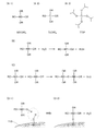
ゾルゲル法を適用して第2の遷移金属を有する材料を被覆する方法について、図2を用いて説明する。
<Sol-gel method>
A method of coating a material having a second transition metal by applying the sol-gel method will be described with reference to FIG.
まず、第2の遷移金属のアルコキシドをアルコールに溶解する。 First, the alkoxide of the second transition metal is dissolved in the alcohol.
図2(A−1)に、第2の遷移金属のアルコキシドの一般式を示す。図2(A−1)の式中のM2は第2の遷移金属のアルコキシドを示す。Rは、炭素数が1乃至18のアルキル基、または置換もしくは無置換の炭素数が6〜13のアリール基を示す。また、図2(A−1)では第2の遷移金属が4価の場合の一般式を示したが、本発明の一態様はこれに限らない。第2の遷移金属は、2価、3価、5価、6価または7価であってもよい。この場合、第2の遷移金属のアルコキシドは第2の遷移金属の価数に応じたアルコキシ基を有する。 FIG. 2 (A-1) shows a general formula of the alkoxide of the second transition metal. M2 in the formula of FIG. 2 (A-1) indicates the alkoxide of the second transition metal. R represents an alkyl group having 1 to 18 carbon atoms or an aryl group having a substituted or unsubstituted carbon number of 6 to 13 carbon atoms. Further, although FIG. 2 (A-1) shows a general formula when the second transition metal is tetravalent, one aspect of the present invention is not limited to this. The second transition metal may be divalent, trivalent, pentavalent, hexavalent or heptavalent. In this case, the alkoxide of the second transition metal has an alkoxy group corresponding to the valence of the second transition metal.
図2(A−2)に、第2の遷移金属としてチタンを適用した場合に用いる、チタンアルコキシドの一般式を示す。図2(A−2)のRは炭素数が1乃至18のアルキル基、または置換もしくは無置換の炭素数が6〜13のアリール基を示す。 FIG. 2 (A-2) shows a general formula of titanium alkoxide used when titanium is applied as the second transition metal. R in FIG. 2 (A-2) represents an alkyl group having 1 to 18 carbon atoms or an aryl group having a substituted or unsubstituted carbon number of 6 to 13 carbon atoms.
たとえばチタンアルコキシドとして、テトラメトキシチタン、テトラエトキシチタン、テトラ−n−プロポキシチタン、テトラ−i−プロポキシチタン(オルトチタン酸テトライソプロピル、チタン(IV)イソプロポキシド、Titanium tetraisopropoxide(IV)、TTIP等と表記することもある)、テトラ−n−ブトキシチタン、テトラ−i−ブトキシチタン、テトラ−sec−ブトキシチタン、テトラ−t−ブトキシチタン等を用いることができる。 For example, as titanium alkoxide, tetramethoxytitanium, tetraethoxytitanium, tetra-n-propoxytitanium, tetra-i-propoxytitanium (tetraisopropyl orthotitanium, titanium (IV) isopropoxide, titanium tetraisopropoxide (IV), TTIP, etc. (Sometimes referred to as), tetra-n-butoxytitanium, tetra-i-butoxytitanium, tetra-sec-butoxytitanium, tetra-t-butoxytitanium and the like can be used.
図2(A−3)に、後述する作製方法で述べるチタンアルコキシドの1種である、チタン(IV)イソプロポキシド(TTIP)の化学式を示す。 FIG. 2 (A-3) shows the chemical formula of titanium (IV) isopropoxide (TTIP), which is one of the titanium alkoxides described in the production method described later.
第2の遷移金属のアルコキシドを溶解させる溶媒としてはアルコール類が好ましく、例えばメタノール、エタノール、プロパノール、2−プロパノール、ブタノール、2−ブタノール等を用いることができる。 Alcohols are preferable as the solvent for dissolving the alkoxide of the second transition metal, and for example, methanol, ethanol, propanol, 2-propanol, butanol, 2-butanol and the like can be used.
次に第2の遷移金属のアルコキシドのアルコール溶液に、リチウム、遷移金属、マグネシウムおよびフッ素を有する複合酸化物の粒子を混合し、水蒸気を含む雰囲気中で撹拌する。 Next, particles of a composite oxide having lithium, transition metal, magnesium and fluorine are mixed with an alcohol solution of the alkoxide of the second transition metal, and the mixture is stirred in an atmosphere containing water vapor.
H2Oを含む雰囲気中に置くことで、図2(B)のように水と第2の遷移金属のアルコキシドの加水分解が起こる。続いて図2(B)の生成物同士で図2(C)のように脱水縮合が起こる。図2(B)に示す加水分解と図2(C)に示す縮合反応が繰り返し生じることで、第2の遷移金属の酸化物のゾルが生成される。この反応が図2(D−1)および図2(D−2)のように複合酸化物の粒子110上でも生じ、粒子110の表面に第2の遷移金属を含む層が形成される。
When placed in an atmosphere containing H 2 O, hydrolysis of water and the alkoxide of the second transition metal occurs as shown in FIG. 2 (B). Subsequently, dehydration condensation occurs between the products of FIG. 2 (B) as shown in FIG. 2 (C). By repeating the hydrolysis shown in FIG. 2 (B) and the condensation reaction shown in FIG. 2 (C), a sol of the oxide of the second transition metal is produced. This reaction also occurs on the
その後、粒子110を回収し、アルコールを気化させる。作製方法の詳細については後述する。
Then, the
なお本実施の形態では、リチウム、第1の遷移金属、典型元素およびフッ素を有する複合酸化物の粒子を正極集電体に塗工する前に、第2の遷移金属を有する材料を被覆する例について説明するが、本発明の一態様はこれに限らない。正極集電体上に、リチウム、第1の遷移金属、典型元素およびフッ素を有する複合酸化物の粒子を含む正極活物質層を形成してから、正極集電体と正極活物質層を共に第2の遷移金属のアルコキシド溶液に浸し、第2の遷移金属を有する材料を被覆してもよい。 In this embodiment, an example of coating a material having a second transition metal before applying particles of a composite oxide having lithium, a first transition metal, a main group element, and fluorine to a positive electrode current collector. However, one aspect of the present invention is not limited to this. A positive electrode active material layer containing particles of lithium, a first transition metal, a typical element, and a composite oxide having fluorine is formed on the positive electrode current collector, and then both the positive electrode current collector and the positive electrode active material layer are formed on the positive electrode current collector. The material having the second transition metal may be coated by immersing it in an alkoxide solution of the second transition metal.
[第3の領域の偏析]
第3の領域103は、スパッタリング法、固相法、ゾルゲル法をはじめとする液相法、等の方法でも形成することができる。特に、マグネシウム等の典型元素源とフッ素源を第1の領域101の材料と混合した後、加熱すると、典型元素が正極活物質粒子の表層部に偏析し、第3の領域103を形成することができる。またこのようにして形成された第3の領域103を有すると、サイクル特性の優れた正極活物質100a、100b、100cとなる。
[Segregation of the third region]
The
上記のように加熱を経て第3の領域103を形成する場合、加熱は、複合酸化物の粒子に第2の遷移金属を含む材料を被覆した後に行うことが好ましい。意外にも第2の遷移金属を含む材料を被覆した後でも、加熱を行うとマグネシウム等の典型元素が粒子の表面に偏析するためである。
When the
なお加熱により典型元素を偏析させる場合、第1の領域101が有するリチウムと第1の遷移金属を含む複合酸化物が多結晶であるときや結晶欠陥が存在するとき、表層部だけでなく、リチウムと第1の遷移金属を含む複合酸化物の粒界近傍や結晶欠陥近傍にも典型元素が偏析しうる。粒界近傍や結晶欠陥近傍に偏析した典型元素は、第1の領域101が有するリチウムと第1の遷移金属を含む複合酸化物の結晶構造のさらなる安定化に寄与しうる。
When the main group element is segregated by heating, when the composite oxide containing lithium and the first transition metal contained in the
また第1の領域101が有するリチウムと第1の遷移金属を含む複合酸化物がクラック部を有するとき、加熱によりクラック部にも典型元素が偏析しうる。また典型元素だけでなく、第2の遷移金属も偏析しうる。クラック部は、粒子表面と同様、電解液と接する領域である。そのため、クラック部に典型元素および第2の遷移金属が偏析し、第3の領域103および第2の領域102が生じることで、電解液と接触する領域を、化学的に安定した材料とすることができる。そのため、サイクル特性の優れた二次電池とすることができる。
Further, when the composite oxide containing lithium and the first transition metal contained in the
出発原料の典型元素(T)とフッ素(F)の比がT:F=1:x(1.5≦x≦4)(原子数比)の範囲であると、効果的に典型元素の偏析が起こるため好ましい。またT:F=1:2(原子数比)程度であることがさらに好ましい。 When the ratio of the main group element (T) to fluorine (F) of the starting material is in the range of T: F = 1: x (1.5 ≦ x ≦ 4) (atomic number ratio), the segregation of the main group element is effective. Is preferable because Further, it is more preferable that T: F = 1: 2 (atomic number ratio).
偏析により形成された第3の領域103は、エピタキシャル成長により形成されているため、第2の領域102と第3の領域103の結晶の配向は、一部で概略一致することがある。つまり第2の領域102と第3の領域103がトポタキシとなることがある。第2の領域102と第3の領域103の結晶の配向が概略一致していると、これらはより良好な被覆層として機能しうる。
Since the
ただし、出発原料として添加したマグネシウム等の典型元素のすべてが、第3の領域103に偏析していなくてもよい。たとえば第1の領域101がマグネシウム等の典型元素をわずかに含んでいてもよい。
However, it is not necessary that all the typical elements such as magnesium added as a starting material are segregated in the
[正極活物質の作製方法]
次に、正極活物質100a、100b、100cの作製方法の一例について説明する。
[Method for producing positive electrode active material]
Next, an example of a method for producing the positive electrode
<ステップ11:出発原料の準備>
はじめに、出発原料を準備する。この工程で用意する原料から、最終的に第1の領域101および第3の領域103が形成される。
<Step 11: Preparation of starting materials>
First, prepare the starting material. From the raw materials prepared in this step, the
第1の領域101が有するリチウムと第1の遷移金属の原料として、リチウム源と、第1の遷移金属源を用意する。また第3の領域103が有する典型元素の化合物の原料として、典型元素源を用意する。
A lithium source and a first transition metal source are prepared as raw materials for the lithium and the first transition metal contained in the
これらに加えて、フッ素源を用意することが好ましい。フッ素は、原料に加えることで、後の工程で第3の領域103が有する典型元素が正極活物質100a、100b、100cの表面に偏析することを助長する効果がある。
In addition to these, it is preferable to prepare a fluorine source. Fluorine, when added to the raw material, has the effect of promoting the segregation of the main group elements of the
リチウム源としては、例えば炭酸リチウム、フッ化リチウムを用いることができる。第1の遷移金属源としては、例えば第1の遷移金属の酸化物を用いることができる。典型元素源としては、例えば第3の領域が有する典型元素の酸化物、第3の領域が有する典型元素のフッ化物等を用いることができる。 As the lithium source, for example, lithium carbonate or lithium fluoride can be used. As the first transition metal source, for example, an oxide of the first transition metal can be used. As a typical element source, for example, an oxide of a typical element contained in the third region, a fluoride of a typical element contained in the third region, or the like can be used.
フッ素源としては、例えばフッ化リチウム、第3の領域が有する典型元素のフッ化物等を用いることができる。つまり、フッ化リチウムはリチウム源としてもフッ素源としても用いることができる。 As the fluorine source, for example, lithium fluoride, fluoride of a typical element having a third region, or the like can be used. That is, lithium fluoride can be used as both a lithium source and a fluorine source.
フッ素源に含まれるフッ素は、典型元素源に含まれる典型元素の、1.0倍以上4倍以下(原子数比)であることが好ましく、1.5倍以上3倍以下(原子数比)であることがさらに好ましい。 Fluorine contained in the fluorine source is preferably 1.0 times or more and 4 times or less (atomic number ratio), and 1.5 times or more and 3 times or less (atomic number ratio) of the main group element contained in the main group element source. Is more preferable.
<ステップ12:出発材料の混合>
次に、リチウム源、第1の遷移金属源、典型元素源を混合する。さらにフッ素源を加えることが好ましい。混合には例えばボールミル、ビーズミルを用いることができる。
<Step 12: Mixing of starting materials>
Next, the lithium source, the first transition metal source, and the main group element source are mixed. Further, it is preferable to add a fluorine source. For example, a ball mill or a bead mill can be used for mixing.
<ステップ13:第1の加熱>
次に、ステップ12で混合した材料を加熱する。本ステップは、焼成、または第1の加熱という場合がある。加熱は800℃以上1100℃以下で行うことが好ましく、900℃以上1000℃以下で行うことがより好ましい。加熱時間は、2時間以上20時間以下とすることが好ましい。焼成は、乾燥空気などの乾燥した雰囲気で行うことが好ましい。乾燥した雰囲気は、たとえば露点が−50℃以下が好ましく、−100℃以下の雰囲気がさらに好ましい。本実施の形態では1000℃で10時間加熱することとし、昇温は200℃/h、露点が−109℃の乾燥空気を10L/minで流すこととする。その後加熱した材料を室温まで冷却する。
<Step 13: First heating>
Next, the mixed materials in step 12 are heated. This step may be referred to as firing or first heating. The heating is preferably performed at 800 ° C. or higher and 1100 ° C. or lower, and more preferably 900 ° C. or higher and 1000 ° C. or lower. The heating time is preferably 2 hours or more and 20 hours or less. The firing is preferably performed in a dry atmosphere such as dry air. The dry atmosphere preferably has a dew point of −50 ° C. or lower, more preferably −100 ° C. or lower. In the present embodiment, heating is performed at 1000 ° C. for 10 hours, and dry air having a temperature rise of 200 ° C./h and a dew point of −109 ° C. is flowed at 10 L / min. The heated material is then cooled to room temperature.
ステップ13の加熱により、層状岩塩型の結晶構造を有する、リチウムと第1の遷移金属の複合酸化物を合成することができる。この時点では、出発材料に含まれた典型元素とフッ素は、複合酸化物中に固溶している。ただし、すでに典型元素の一部が、複合酸化物の表面に偏在している場合もある。 By heating in step 13, a composite oxide of lithium and a first transition metal having a layered rock salt type crystal structure can be synthesized. At this point, the main group elements and fluorine contained in the starting material are solid-solved in the composite oxide. However, some of the main group elements may already be unevenly distributed on the surface of the composite oxide.
また、出発原料としてあらかじめ合成されたリチウム、コバルト、フッ素、マグネシウムを含む複合酸化物の粒子を用いてもよい。この場合、ステップ12およびステップ13を省略することができる。たとえば、日本化学工業株式会社製の、コバルト酸リチウム粒子(商品名:C−20F)を出発原料の一として用いることができる。これは粒径が約20μmであり、表面からXPSで分析可能な領域にフッ素、マグネシウム、カルシウム、ナトリウム、シリコン、硫黄、リンを含むコバルト酸リチウム粒子である。 In addition, particles of a composite oxide containing lithium, cobalt, fluorine, and magnesium that have been synthesized in advance may be used as a starting material. In this case, steps 12 and 13 can be omitted. For example, lithium cobalt oxide particles (trade name: C-20F) manufactured by Nippon Chemical Industrial Co., Ltd. can be used as one of the starting materials. This is a lithium cobalt oxide particle having a particle size of about 20 μm and containing fluorine, magnesium, calcium, sodium, silicon, sulfur, and phosphorus in a region that can be analyzed by XPS from the surface.
<ステップ14:第2の遷移金属で被覆>
次に、リチウムと第1の遷移金属の複合酸化物を室温まで冷却する。そしてリチウムと第1の遷移金属の複合酸化物粒子の表面を、第2の遷移金属を有する材料で被覆する。本作製方法例では、ゾルゲル法を適用することとする。
<Step 14: Covered with a second transition metal>
Next, the composite oxide of lithium and the first transition metal is cooled to room temperature. Then, the surface of the composite oxide particles of lithium and the first transition metal is coated with a material having the second transition metal. In this production method example, the sol-gel method is applied.
まずアルコールに溶解させた第2の遷移金属のアルコキシドと、リチウムと第1の遷移金属の複合酸化物粒子と、を混合する。 First, the alkoxide of the second transition metal dissolved in alcohol and the composite oxide particles of lithium and the first transition metal are mixed.
たとえば第2の遷移金属としてチタンを用いる場合、第2の遷移金属のアルコキシドとしてはたとえばTTIPを用いることができる。またアルコールとしては、たとえばイソプロパノールを用いることができる。 For example, when titanium is used as the second transition metal, for example, TTIP can be used as the alkoxide of the second transition metal. Further, as the alcohol, for example, isopropanol can be used.
次に、上記混合液を、水蒸気を含む雰囲気下で撹拌する。撹拌はたとえばマグネチックスターラーで行うことができる。撹拌時間は、雰囲気中の水とTTIPが加水分解および重縮合反応を起こすのに十分な時間であればよく、例えば4時間、25℃、湿度90%RH(Relative Humidity、相対湿度)の条件下で行うことができる。 Next, the mixture is stirred in an atmosphere containing water vapor. Stirring can be done, for example, with a magnetic stirrer. The stirring time may be a time sufficient for water in the atmosphere and TTIP to cause a hydrolysis and polycondensation reaction, for example, under the conditions of 4 hours, 25 ° C., and 90% humidity RH (Relative Humidity). Can be done with.
上記のように、雰囲気中の水とTTIPを反応させることで、液体の水を加える場合よりもゆっくりとゾルゲル反応を進めることができる。また常温でチタンアルコキシドと水を反応させることで、たとえば溶媒のアルコールの沸点を超える温度で加熱を行う場合よりもゆっくりとゾルゲル反応を進めることができる。ゆっくりとゾルゲル反応を進めることで、厚さが均一で良質なチタンを含む被覆層を形成することができる。 As described above, by reacting water in the atmosphere with TTIP, the sol-gel reaction can proceed more slowly than when liquid water is added. Further, by reacting titanium alkoxide with water at room temperature, the sol-gel reaction can proceed more slowly than, for example, when heating is performed at a temperature exceeding the boiling point of alcohol as a solvent. By slowly advancing the sol-gel reaction, a coating layer containing titanium having a uniform thickness and good quality can be formed.
上記の処理を終えた混合液から、沈殿物を回収する。回収方法としては、ろ過、遠心分離、蒸発乾固等を適用することができる。本実施の形態ではろ過により回収することとする。ろ過には紙フィルターを用い、残渣はチタンアルコキシドを溶解させた溶媒と同じアルコールで洗浄することとする。 The precipitate is recovered from the mixed solution after the above treatment. As a recovery method, filtration, centrifugation, evaporation to dryness, or the like can be applied. In the present embodiment, it is collected by filtration. A paper filter is used for filtration, and the residue is washed with the same alcohol as the solvent in which the titanium alkoxide is dissolved.
次に、回収した残渣を乾燥する。本実施の形態では、70℃で1時間、真空乾燥することとする。 Next, the recovered residue is dried. In this embodiment, vacuum drying is performed at 70 ° C. for 1 hour.
<ステップ15:第2の加熱>
次に、ステップ14で作製した、第2の遷移金属を有する材料で被覆された、複合酸化物粒子を加熱する。本ステップは、第2の加熱という場合がある。加熱時間は、規定温度の範囲内での保持時間を50時間以下とすることが好ましく、2時間以上10時間以下とすることがより好ましく、1時間以上3時間以下で行うことがさらに好ましい。加熱時間が短すぎると典型元素の偏析が起こらない恐れがあるが、長すぎると、第2の遷移金属の拡散が進みすぎて良好な第2の領域102が形成できない恐れがある。
<Step 15: Second heating>
Next, the composite oxide particles prepared in step 14 and coated with the material having the second transition metal are heated. This step may be referred to as a second heating. As for the heating time, the holding time within the specified temperature range is preferably 50 hours or less, more preferably 2 hours or more and 10 hours or less, and further preferably 1 hour or more and 3 hours or less. If the heating time is too short, segregation of the main group element may not occur, but if it is too long, the diffusion of the second transition metal may proceed too much and a good
規定温度としては500℃以上1200℃以下が好ましく、800℃以上1000℃以下がより好ましい。規定温度が低すぎると典型元素および第2の遷移金属の偏析が起こらない恐れがある。しかし高すぎても複合酸化物粒子中の第1の遷移金属が還元され、複合酸化物粒子が分解してしまう、複合酸化物粒子中のリチウムと第1の遷移金属の層状構造が保てない、等のおそれがある。 The specified temperature is preferably 500 ° C. or higher and 1200 ° C. or lower, and more preferably 800 ° C. or higher and 1000 ° C. or lower. If the specified temperature is too low, segregation of the main group element and the second transition metal may not occur. However, if it is too high, the first transition metal in the composite oxide particles is reduced and the composite oxide particles are decomposed, and the layered structure of lithium and the first transition metal in the composite oxide particles cannot be maintained. , Etc. may occur.
本実施の形態では、規定温度を800℃として2時間保持することとし、昇温は200℃/h、乾燥空気の流量は10L/minとする。 In the present embodiment, the specified temperature is set to 800 ° C. and the temperature is maintained for 2 hours, the temperature rise is 200 ° C./h, and the flow rate of dry air is 10 L / min.
ステップ15の加熱によって、リチウムと第1の遷移金属の複合酸化物と、その上に被覆された第2の遷移金属の酸化物がトポタキシとなる。つまり第1の領域101と第2の領域102がトポタキシとなる。
By heating in step 15, the composite oxide of lithium and the first transition metal and the oxide of the second transition metal coated on the composite oxide become topotaxis. That is, the
またステップ15の加熱によって、リチウムと第1の遷移金属の複合酸化物粒子の内部に固溶していた典型元素が表面に偏在して固溶、つまり偏析し、典型元素の化合物となり、第3の領域103を形成する。このとき典型元素の化合物は、第2の領域102からヘテロエピタキシャル成長する。つまり第2の領域102と第3の領域103がトポタキシとなる。
Further, by the heating in step 15, the typical element that was solid-solved inside the composite oxide particles of lithium and the first transition metal is unevenly distributed on the surface and solid-solved, that is, segregated to become a compound of the typical element, and the
第2の領域102および第3の領域103の結晶の配向が概略一致し、第1の領域101と安定した結合を有するため、正極活物質100a、100b、100cを二次電池に用いた際、充放電によって生じる第1の領域101の結晶構造の変化を効果的に抑制できる。また、充電によって第1の領域101からリチウムが抜けた状態となっても、安定した結合を有する表層部によって第1の領域101からコバルト等の第1の遷移金属や酸素が離脱するのを抑制することができる。さらに、電解液と接触する領域を、化学的に安定した材料とすることができる。そのため、サイクル特性の優れた二次電池とすることができる。
Since the crystal orientations of the
なお、第1の領域101と第2の領域102は一部がトポタキシであればよく、第1の領域101と第2の領域102のすべてがトポタキシである必要はない。また、第2の領域102と第3の領域103は一部がトポタキシであればよく、第2の領域102と第3の領域103のすべてがトポタキシである必要はない。
It should be noted that the
また、第3の領域が有する典型元素の化合物が、酸素を有する場合は、酸素を含む雰囲気でステップ15の加熱を行うことが好ましい。酸素を含む雰囲気で加熱することで、第3の領域103の形成が促進される。
When the compound of the main group element contained in the third region has oxygen, it is preferable to perform the heating in step 15 in an atmosphere containing oxygen. Heating in an oxygen-containing atmosphere promotes the formation of the
また、出発原料に含まれたフッ素により、典型元素の偏析が促進される。 In addition, the fluorine contained in the starting material promotes segregation of typical elements.
このように、本発明の一態様である正極活物質の作製方法では、第2の領域102を形成する元素を被覆した後、加熱を行うことで第3の領域103を形成し、正極活物質100a、100b、100cの表面に2種の領域を形成することが可能となる。つまり通常ならば、表層部に2種の領域を設けるためには2回の被覆工程が必要であるところ、本発明の一態様である正極活物質の作製方法は1回の被覆工程(ゾルゲル工程)のみでよいため、生産性のよい作製方法である。
As described above, in the method for producing a positive electrode active material, which is one aspect of the present invention, the
<ステップ16:冷却>
次に、ステップ15で加熱した粒子を、室温まで冷却する。降温時間は長くとると、トポタキシとさせやすく好ましい。たとえば、保持温度から室温までの降温時間は、昇温と同じかそれ以上の時間、具体的には10時間以上50時間以下とすることが好ましい。
<Step 16: Cooling>
Next, the particles heated in step 15 are cooled to room temperature. It is preferable to take a long time for lowering the temperature because it is easy to make it topotaxy. For example, the temperature lowering time from the holding temperature to room temperature is preferably the same as or longer than the temperature rising, specifically 10 hours or more and 50 hours or less.
<ステップ17:回収>
次に、冷却された粒子を回収する。さらに、粒子をふるいにかけることが好ましい。上記の工程で、第1の領域101、第2の領域102および第3の領域103を有する正極活物質100a、100b、100cを作製することができる。
<Step 17: Recovery>
Next, the cooled particles are collected. In addition, it is preferable to sift the particles. In the above steps, positive electrode
そして、得られた正極活物質100a、100b、100cと、導電補助剤である気相成長炭素繊維131a、131bと、バインダ130とを含む活物質層を正極集電体上に形成する。正極活物質100a、100b、100c、気相成長炭素繊維131a、131b、及びバインダ130を含む正極用ペーストを作製し、正極集電体に塗布した後、乾燥させ、ロールなどで加圧成形する。高密度の電極密度を得るため、1050kN/m以上の圧力でプレスすることで電極密度を4.0g/cm3以上とすることができる。図1は、正極集電体(図示しない)上に形成された活物質層の断面の一例を示している。
Then, an active material layer containing the obtained positive electrode
なお、バインダ130としては、例えば、スチレン−ブタジエンゴム(SBR)、スチレン−イソプレン−スチレンゴム、アクリロニトリル−ブタジエンゴム、ブタジエンゴム、エチレン−プロピレン−ジエン共重合体などのゴム材料を用いることが好ましい。またバインダとして、フッ素ゴムを用いることができる。
As the
また、バインダとしては、例えば水溶性の高分子を用いることが好ましい。水溶性の高分子としては、例えば多糖類などを用いることができる。多糖類としては、カルボキシメチルセルロース(CMC)、メチルセルロース、エチルセルロース、ヒドロキシプロピルセルロース、ジアセチルセルロース、再生セルロースなどのセルロース誘導体や、澱粉などを用いることができる。また、これらの水溶性の高分子を、前述のゴム材料と併用して用いると、さらに好ましい。 Further, as the binder, for example, it is preferable to use a water-soluble polymer. As the water-soluble polymer, for example, a polysaccharide or the like can be used. As the polysaccharide, cellulose derivatives such as carboxymethyl cellulose (CMC), methyl cellulose, ethyl cellulose, hydroxypropyl cellulose, diacetyl cellulose and regenerated cellulose, starch and the like can be used. Further, it is more preferable to use these water-soluble polymers in combination with the above-mentioned rubber material.
または、バインダとしては、ポリスチレン、ポリアクリル酸メチル、ポリメタクリル酸メチル(PMMA)、ポリアクリル酸ナトリウム、ポリビニルアルコール(PVA)、ポリエチレンオキシド(PEO)、ポリプロピレンオキシド、ポリイミド、ポリ塩化ビニル、ポリテトラフルオロエチレン、ポリエチレン、ポリプロピレン、ポリイソブチレン、ポリエチレンテレフタレート、ナイロン、ポリフッ化ビニリデン(PVdF)、ポリアクリロニトリル(PAN)、エチレンプロピレンジエンポリマー、ポリ酢酸ビニル、ニトロセルロース等の材料を用いることが好ましい。 Alternatively, the binder includes polystyrene, methyl polyacrylate, polymethyl methacrylate (PMMA), sodium polyacrylate, polyvinyl alcohol (PVA), polyethylene oxide (PEO), polypropylene oxide, polyimide, polyvinyl chloride, and polytetrafluoro. It is preferable to use materials such as ethylene, polyethylene, polypropylene, polyisobutylene, polyethylene terephthalate, nylon, polyvinylidene fluoride (PVdF), polyacrylonitrile (PAN), ethylenepropylene diene polymer, polyvinyl acetate, and nitrocellulose.
バインダは上記のうち複数を組み合わせて使用してもよい。 The binder may be used in combination of a plurality of the above.
<正極集電体>
正極集電体としては、ステンレス、金、白金、アルミニウム、チタン等の金属、及びこれらの合金など、導電性が高い材料をもちいることができる。また正極集電体に用いる材料は、正極の電位で溶出しないことが好ましい。また、シリコン、チタン、ネオジム、スカンジウム、モリブデンなどの耐熱性を向上させる元素が添加されたアルミニウム合金を用いることができる。また、シリコンと反応してシリサイドを形成する金属元素で形成してもよい。シリコンと反応してシリサイドを形成する金属元素としては、ジルコニウム、チタン、ハフニウム、バナジウム、ニオブ、タンタル、クロム、モリブデン、タングステン、コバルト、ニッケル等がある。集電体は、箔状、板状(シート状)、網状、パンチングメタル状、エキスパンドメタル状等の形状を適宜用いることができる。集電体は、厚みが5μm以上30μm以下のものを用いるとよい。
<Positive current collector>
As the positive electrode current collector, a material having high conductivity such as metals such as stainless steel, gold, platinum, aluminum and titanium, and alloys thereof can be used. Further, it is preferable that the material used for the positive electrode current collector does not elute at the potential of the positive electrode. Further, an aluminum alloy to which an element for improving heat resistance such as silicon, titanium, neodymium, scandium, and molybdenum is added can be used. Further, it may be formed of a metal element that reacts with silicon to form VDD. Examples of metal elements that react with silicon to form silicide include zirconium, titanium, hafnium, vanadium, niobium, tantalum, chromium, molybdenum, tungsten, cobalt, nickel and the like. As the current collector, a foil shape, a plate shape (sheet shape), a net shape, a punching metal shape, an expanded metal shape, or the like can be appropriately used. It is preferable to use a current collector having a thickness of 5 μm or more and 30 μm or less.
(実施の形態2)
実施の形態1では、正極の作製例を示したが、本実施の形態では、正極、負極および電解液が、外装体に包まれている二次電池を例にとって説明する。
(Embodiment 2)
In the first embodiment, an example of producing a positive electrode is shown, but in the present embodiment, a secondary battery in which the positive electrode, the negative electrode and the electrolytic solution are wrapped in an exterior body will be described as an example.
[負極]
負極は、負極活物質層および負極集電体を有する。また、負極活物質層は、導電助剤およびバインダを有していてもよい。
[Negative electrode]
The negative electrode has a negative electrode active material layer and a negative electrode current collector. Further, the negative electrode active material layer may have a conductive auxiliary agent and a binder.
<負極活物質>
負極活物質としては、例えば合金系材料や炭素系材料等を用いることができる。
<Negative electrode active material>
As the negative electrode active material, for example, an alloy-based material, a carbon-based material, or the like can be used.
負極活物質として、リチウムとの合金化・脱合金化反応により充放電反応を行うことが可能な元素を用いることができる。例えば、シリコン、スズ、ガリウム、アルミニウム、ゲルマニウム、鉛、アンチモン、ビスマス、銀、亜鉛、カドミウム、インジウム等のうち少なくとも一つを含む材料を用いることができる。このような元素は炭素と比べて容量が大きく、特にシリコンは理論容量が4200mAh/gと高い。このため、負極活物質にシリコンを用いることが好ましい。また、これらの元素を有する化合物を用いてもよい。例えば、SiO、Mg2Si、Mg2Ge、SnO、SnO2、Mg2Sn、SnS2、V2Sn3、FeSn2、CoSn2、Ni3Sn2、Cu6Sn5、Ag3Sn、Ag3Sb、Ni2MnSb、CeSb3、LaSn3、La3Co2Sn7、CoSb3、InSb、SbSn等がある。ここで、リチウムとの合金化・脱合金化反応により充放電反応を行うことが可能な元素、および該元素を有する化合物等を合金系材料と呼ぶ場合がある。 As the negative electrode active material, an element capable of performing a charge / discharge reaction by an alloying / dealloying reaction with lithium can be used. For example, a material containing at least one of silicon, tin, gallium, aluminum, germanium, lead, antimony, bismuth, silver, zinc, cadmium, indium and the like can be used. Such elements have a larger capacity than carbon, and silicon in particular has a high theoretical capacity of 4200 mAh / g. Therefore, it is preferable to use silicon as the negative electrode active material. Moreover, you may use the compound which has these elements. For example, SiO, Mg 2 Si, Mg 2 Ge, SnO, SnO 2 , Mg 2 Sn, SnS 2 , V 2 Sn 3 , FeSn 2 , CoSn 2 , Ni 3 Sn 2 , Cu 6 Sn 5 , Ag 3 Sn, Ag. There are 3 Sb, Ni 2 MnSb, CeSb 3 , LaSn 3 , La 3 Co 2 Sn 7 , CoSb 3 , InSb, SbSn and the like. Here, an element capable of performing a charge / discharge reaction by an alloying / dealloying reaction with lithium, a compound having the element, and the like may be referred to as an alloy-based material.
本明細書等において、SiOは例えば一酸化シリコンを指す。あるいはSiOは、SiOxと表すこともできる。ここでxは1近傍の値を有することが好ましい。例えばxは、0.2以上1.5以下が好ましく、0.3以上1.2以下がより好ましい。 In the present specification and the like, SiO refers to, for example, silicon monoxide. Alternatively, SiO can also be expressed as SiO x. Here, x preferably has a value in the vicinity of 1. For example, x is preferably 0.2 or more and 1.5 or less, and more preferably 0.3 or more and 1.2 or less.
炭素系材料としては、黒鉛、易黒鉛化性炭素(ソフトカーボン)、難黒鉛化性炭素(ハードカーボン)、カーボンナノチューブ、グラフェン、カーボンブラック等を用いればよい。 As the carbon-based material, graphite, easily graphitizable carbon (soft carbon), non-graphitizable carbon (hard carbon), carbon nanotubes, graphene, carbon black and the like may be used.
黒鉛としては、人造黒鉛や、天然黒鉛等が挙げられる。人造黒鉛としては例えば、メソカーボンマイクロビーズ(MCMB)、コークス系人造黒鉛、ピッチ系人造黒鉛等が挙げられる。ここで人造黒鉛として、球状の形状を有する球状黒鉛を用いることができる。例えば、MCMBは球状の形状を有する場合があり、好ましい。また、MCMBはその表面積を小さくすることが比較的容易であり、好ましい場合がある。天然黒鉛としては例えば、鱗片状黒鉛、球状化天然黒鉛等が挙げられる。 Examples of graphite include artificial graphite and natural graphite. Examples of the artificial graphite include mesocarbon microbeads (MCMB), coke-based artificial graphite, pitch-based artificial graphite and the like. Here, as the artificial graphite, spheroidal graphite having a spherical shape can be used. For example, MCMB may have a spherical shape, which is preferable. In addition, MCMB is relatively easy to reduce its surface area and may be preferable. Examples of natural graphite include scaly graphite and spheroidized natural graphite.
黒鉛はリチウムイオンが黒鉛に挿入されたとき(リチウム−黒鉛層間化合物の生成時)にリチウム金属と同程度に低い電位を示す(0.05V以上0.3V以下 vs.Li/Li+)。これにより、リチウムイオン二次電池は高い作動電圧を示すことができる。さらに、黒鉛は、単位体積当たりの容量が比較的高い、体積膨張が比較的小さい、安価である、リチウム金属に比べて安全性が高い等の利点を有するため、好ましい。 Graphite exhibits a potential as low as lithium metal when lithium ions are inserted into graphite (during the formation of a lithium-graphite intercalation compound) (0.05 V or more and 0.3 V or less vs. Li / Li +). As a result, the lithium ion secondary battery can exhibit a high operating voltage. Further, graphite is preferable because it has advantages such as relatively high capacity per unit volume, relatively small volume expansion, low cost, and high safety as compared with lithium metal.
また、負極活物質として、二酸化チタン(TiO2)、リチウムチタン酸化物(Li4Ti5O12)、リチウム−黒鉛層間化合物(LixC6)、五酸化ニオブ(Nb2O5)、酸化タングステン(WO2)、酸化モリブデン(MoO2)等の酸化物を用いることができる。 Further, as the negative electrode active material, titanium dioxide (TiO 2 ), lithium titanium oxide (Li 4 Ti 5 O 12 ), lithium-graphite interlayer compound (Li x C 6 ), niobium pentoxide (Nb 2 O 5 ), oxidation. Oxides such as tungsten (WO 2 ) and molybdenum oxide (MoO 2 ) can be used.
また、負極活物質として、リチウムと遷移金属の複窒化物である、Li3N型構造をもつLi3−xMxN(M=Co、Ni、Cu)を用いることができる。例えば、Li2.6Co0.4N3は大きな充放電容量(900mAh/g、1890mAh/cm3)を示し好ましい。 Further, as the negative electrode active material, Li 3-x M x N (M = Co, Ni, Cu) having a Li 3 N type structure, which is a compound nitride of lithium and a transition metal, can be used. For example, Li 2.6 Co 0.4 N 3 shows a large charge / discharge capacity (900 mAh / g, 1890 mAh / cm 3 ) and is preferable.
リチウムと遷移金属の複窒化物を用いると、負極活物質中にリチウムイオンを含むため、正極活物質としてリチウムイオンを含まないV2O5、Cr3O8等の材料と組み合わせることができ好ましい。なお、正極活物質にリチウムイオンを含む材料を用いる場合でも、あらかじめ正極活物質に含まれるリチウムイオンを脱離させることで、負極活物質としてリチウムと遷移金属の複窒化物を用いることができる。 When a double nitride of lithium and a transition metal is used, lithium ions are contained in the negative electrode active material, so that it can be combined with materials such as V 2 O 5 and Cr 3 O 8 which do not contain lithium ions as the positive electrode active material, which is preferable. .. Even when a material containing lithium ions is used as the positive electrode active material, a double nitride of lithium and a transition metal can be used as the negative electrode active material by desorbing the lithium ions contained in the positive electrode active material in advance.
また、コンバージョン反応が生じる材料を負極活物質として用いることもできる。例えば、酸化コバルト(CoO)、酸化ニッケル(NiO)、酸化鉄(FeO)等の、リチウムとの合金を作らない遷移金属酸化物を負極活物質に用いてもよい。コンバージョン反応が生じる材料としては、さらに、Fe2O3、CuO、Cu2O、RuO2、Cr2O3等の酸化物、CoS0.89、NiS、CuS等の硫化物、Zn3N2、Cu3N、Ge3N4等の窒化物、NiP2、FeP2、CoP3等のリン化物、FeF3、BiF3等のフッ化物でも起こる。 Further, a material that causes a conversion reaction can also be used as the negative electrode active material. For example, a transition metal oxide that does not form an alloy with lithium, such as cobalt oxide (CoO), nickel oxide (NiO), and iron oxide (FeO), may be used as the negative electrode active material. Materials that cause a conversion reaction include oxides such as Fe 2 O 3 , CuO, Cu 2 O, RuO 2 , Cr 2 O 3 , sulfides such as CoS 0.89 , NiS, and CuS, and Zn 3 N 2. , Cu 3 N, Ge 3 N 4 and other nitrides, NiP 2 , FeP 2 and CoP 3 and other phosphates, and FeF 3 and BiF 3 and other fluorides.
負極活物質層が有することのできる導電助剤およびバインダとしては、正極活物質層が有することのできる導電助剤およびバインダと同様の材料を用いることができる。 As the conductive auxiliary agent and the binder that the negative electrode active material layer can have, the same material as the conductive auxiliary agent and the binder that the positive electrode active material layer can have can be used.
<負極集電体>
負極集電体には、正極集電体と同様の材料を用いることができる。なお負極集電体は、リチウム等のキャリアイオンと合金化しない材料を用いることが好ましい。
<Negative electrode current collector>
The same material as the positive electrode current collector can be used for the negative electrode current collector. The negative electrode current collector preferably uses a material that does not alloy with carrier ions such as lithium.
[電解液]
電解液は、溶媒と電解質を有する。電解液の溶媒としては、非プロトン性有機溶媒が好ましく、例えば、エチレンカーボネート(EC)、フルオロエチレンカーボネート(FEC)、プロピレンカーボネート(PC)、ブチレンカーボネート、クロロエチレンカーボネート、ビニレンカーボネート、γ−ブチロラクトン、γ−バレロラクトン、ジメチルカーボネート(DMC)、ジエチルカーボネート(DEC)、エチルメチルカーボネート(EMC)、ギ酸メチル、酢酸メチル、酢酸エチル、プロピオン酸メチル、プロピオン酸エチル、プロピオン酸プロピル、酪酸メチル、1,3−ジオキサン、1,4−ジオキサン、ジメトキシエタン(DME)、ジメチルスルホキシド、ジエチルエーテル、メチルジグライム、アセトニトリル、ベンゾニトリル、テトラヒドロフラン、スルホラン、スルトン等の1種、又はこれらのうちの2種以上を任意の組み合わせおよび比率で用いることができる。
[Electrolytic solution]
The electrolytic solution has a solvent and an electrolyte. The solvent of the electrolytic solution is preferably an aproton organic solvent, for example, ethylene carbonate (EC), fluoroethylene carbonate (FEC), propylene carbonate (PC), butylene carbonate, chloroethylene carbonate, vinylene carbonate, γ-butyrolactone, γ-Valerolactone, dimethyl carbonate (DMC), diethyl carbonate (DEC), ethyl methyl carbonate (EMC), methyl formate, methyl acetate, ethyl acetate, methyl propionate, ethyl propionate, propyl propionate, methyl butyrate, 1, One of 3-dioxane, 1,4-dioxane, dimethoxyethane (DME), dimethyl sulfoxide, diethyl ether, methyl diglime, acetonitrile, benzonitrile, tetrahydrofuran, sulfolane, sulton, etc., or two or more of them. It can be used in any combination and ratio.
また、電解液の溶媒として、難燃性および難揮発性であるイオン液体(常温溶融塩)を一つ又は複数用いることで、二次電池の内部短絡や、過充電等によって内部温度が上昇しても、二次電池の破裂や発火などを防ぐことができる。イオン液体は、カチオンとアニオンからなり、有機カチオンとアニオンとを含む。電解液に用いる有機カチオンとして、四級アンモニウムカチオン、三級スルホニウムカチオン、および四級ホスホニウムカチオン等の脂肪族オニウムカチオンや、イミダゾリウムカチオンおよびピリジニウムカチオン等の芳香族カチオンが挙げられる。また、電解液に用いるアニオンとして、1価のアミド系アニオン、1価のメチド系アニオン、フルオロスルホン酸アニオン、パーフルオロアルキルスルホン酸アニオン、テトラフルオロボレートアニオン、パーフルオロアルキルボレートアニオン、ヘキサフルオロホスフェートアニオン、またはパーフルオロアルキルホスフェートアニオン等が挙げられる。 Further, by using one or more flame-retardant and volatile ionic liquids (normal temperature molten salt) as the solvent of the electrolytic solution, the internal temperature rises due to an internal short circuit of the secondary battery, overcharging, or the like. However, it is possible to prevent the secondary battery from exploding or catching fire. Ionic liquids consist of cations and anions, including organic cations and anions. Examples of the organic cation used in the electrolytic solution include aliphatic onium cations such as quaternary ammonium cations, tertiary sulfonium cations, and quaternary phosphonium cations, and aromatic cations such as imidazolium cations and pyridinium cations. Further, as anions used in the electrolytic solution, monovalent amide anion, monovalent methide anion, fluorosulfonic anion, perfluoroalkyl sulfonic acid anion, tetrafluoroborate anion, perfluoroalkyl borate anion, hexafluorophosphate anion. , Or perfluoroalkyl phosphate anion and the like.
また、上記の溶媒に溶解させる電解質としては、例えばLiPF6、LiClO4、LiAsF6、LiBF4、LiAlCl4、LiSCN、LiBr、LiI、Li2SO4、Li2B10Cl10、Li2B12Cl12、LiCF3SO3、LiC4F9SO3、LiC(CF3SO2)3、LiC(C2F5SO2)3、LiN(CF3SO2)2、LiN(C4F9SO2)(CF3SO2)、LiN(C2F5SO2)2等のリチウム塩を一種、又はこれらのうちの二種以上を任意の組み合わせおよび比率で用いることができる。
As the electrolytes dissolved in the above solvent, for example LiPF 6, LiClO 4, LiAsF 6 ,
二次電池に用いる電解液は、粒状のごみや電解液の構成元素以外の元素(以下、単に「不純物」ともいう。)の含有量が少ない高純度化された電解液を用いることが好ましい。具体的には、電解液に対する不純物の重量比を1%以下、好ましくは0.1%以下、より好ましくは0.01%以下とすることが好ましい。 As the electrolytic solution used for the secondary battery, it is preferable to use a highly purified electrolytic solution having a small content of elements other than granular dust and constituent elements of the electrolytic solution (hereinafter, also simply referred to as “impurities”). Specifically, the weight ratio of impurities to the electrolytic solution is preferably 1% or less, preferably 0.1% or less, and more preferably 0.01% or less.
また、電解液にビニレンカーボネート、プロパンスルトン(PS)、tert−ブチルベンゼン(TBB)、フルオロエチレンカーボネート(FEC)、LiBOB、またスクシノニトリル、アジポニトリル等のジニトリル化合物などの添加剤を添加してもよい。添加する材料の濃度は、例えば溶媒全体に対して0.1wt%以上5wt%以下とすればよい。 Further, even if an additive such as vinylene carbonate, propane sultone (PS), tert-butylbenzene (TBB), fluoroethylene carbonate (FEC), LiBOB, or a dinitrile compound such as succinonitrile or adiponitrile is added to the electrolytic solution, it may be added. Good. The concentration of the material to be added may be, for example, 0.1 wt% or more and 5 wt% or less with respect to the entire solvent.
また、ポリマーを電解液で膨潤させたポリマーゲル電解質を用いてもよい。 Alternatively, a polymer gel electrolyte obtained by swelling the polymer with an electrolytic solution may be used.
ポリマーゲル電解質を用いることで、漏液性等に対する安全性が高まる。また、二次電池の薄型化および軽量化が可能である。 By using the polymer gel electrolyte, the safety against liquid leakage and the like is enhanced. In addition, the secondary battery can be made thinner and lighter.
ゲル化されるポリマーとして、シリコーンゲル、アクリルゲル、アクリロニトリルゲル、ポリエチレンオキサイド系ゲル、ポリプロピレンオキサイド系ゲル、フッ素系ポリマーのゲル等を用いることができる。 As the gelled polymer, silicone gel, acrylic gel, acrylonitrile gel, polyethylene oxide gel, polypropylene oxide gel, fluoropolymer gel and the like can be used.
ポリマーとしては、例えばポリエチレンオキシド(PEO)などのポリアルキレンオキシド構造を有するポリマーや、PVDF、およびポリアクリロニトリル等、およびそれらを含む共重合体等を用いることができる。例えばPVDFとヘキサフルオロプロピレン(HFP)の共重合体であるPVDF−HFPを用いることができる。また、形成されるポリマーは、多孔質形状を有してもよい。 As the polymer, for example, a polymer having a polyalkylene oxide structure such as polyethylene oxide (PEO), PVDF, polyacrylonitrile, etc., and a copolymer containing them can be used. For example, PVDF-HFP, which is a copolymer of PVDF and hexafluoropropylene (HFP), can be used. Further, the polymer to be formed may have a porous shape.
また、電解液の代わりに、硫化物系や酸化物系等の無機物材料を有する固体電解質や、PEO(ポリエチレンオキシド)系等の高分子材料を有する固体電解質を用いることができる。固体電解質を用いる場合には、セパレータやスペーサの設置が不要となる。また、電池全体を固体化できるため、漏液のおそれがなくなり安全性が飛躍的に向上する。 Further, instead of the electrolytic solution, a solid electrolyte having an inorganic material such as a sulfide type or an oxide type, or a solid electrolyte having a polymer material such as PEO (polyethylene oxide) type can be used. When a solid electrolyte is used, it is not necessary to install a separator or a spacer. In addition, since the entire battery can be solidified, there is no risk of liquid leakage and safety is dramatically improved.
[セパレータ]
また二次電池は、セパレータを有することが好ましい。セパレータとしては、例えば、紙、不織布、ガラス繊維、セラミックス、或いはナイロン(ポリアミド)、ビニロン(ポリビニルアルコール系繊維)、ポリエステル、アクリル、ポリオレフィン、ポリウレタンを用いた合成繊維等で形成されたものを用いることができる。セパレータはエンベロープ状に加工し、正極または負極のいずれか一方を包むように配置することが好ましい。
[Separator]
Further, the secondary battery preferably has a separator. As the separator, for example, paper, non-woven fabric, glass fiber, ceramics, or one formed of nylon (polyamide), vinylon (polyvinyl alcohol-based fiber), polyester, acrylic, polyolefin, synthetic fiber using polyurethane, etc. shall be used. Can be done. It is preferable that the separator is processed into an envelope shape and arranged so as to wrap either the positive electrode or the negative electrode.
セパレータは多層構造であってもよい。たとえばポリプロピレン、ポリエチレン等の有機材料フィルムに、セラミック系材料、フッ素系材料、ポリアミド系材料、またはこれらを混合したもの等をコートすることができる。セラミック系材料としては、たとえば酸化アルミニウム粒子、酸化シリコン粒子等を用いることができる。フッ素系材料としては、たとえばPVDF、ポリテトラフルオロエチレン等を用いることができる。ポリアミド系材料としては、たとえばナイロン、アラミド(メタ系アラミド、パラ系アラミド)等を用いることができる。 The separator may have a multi-layer structure. For example, an organic material film such as polypropylene or polyethylene can be coated with a ceramic material, a fluorine material, a polyamide material, or a mixture thereof. As the ceramic material, for example, aluminum oxide particles, silicon oxide particles and the like can be used. As the fluorine-based material, for example, PVDF, polytetrafluoroethylene and the like can be used. As the polyamide-based material, for example, nylon, aramid (meth-based aramid, para-based aramid) and the like can be used.
セラミック系材料をコートすると耐酸化性が向上するため、高電圧充放電の際のセパレータの劣化を抑制し、二次電池の信頼性を向上させることができる。またフッ素系材料をコートするとセパレータと電極が密着しやすくなり、出力特性を向上させることができる。ポリアミド系材料、特にアラミドをコートすると、耐熱性が向上するため、二次電池の安全性を向上させることができる。 Since the oxidation resistance is improved by coating with a ceramic material, deterioration of the separator during high voltage charging / discharging can be suppressed, and the reliability of the secondary battery can be improved. Further, when a fluorine-based material is coated, the separator and the electrode are easily brought into close contact with each other, and the output characteristics can be improved. Coating a polyamide-based material, particularly aramid, improves heat resistance and thus can improve the safety of the secondary battery.
たとえばポリプロピレンのフィルムの両面に酸化アルミニウムとアラミドの混合材料をコートしてもよい。また、ポリプロピレンのフィルムの、正極と接する面に酸化アルミニウムとアラミドの混合材料をコートし、負極と接する面にフッ素系材料をコートしてもよい。 For example, a mixed material of aluminum oxide and aramid may be coated on both sides of a polypropylene film. Further, the surface of the polypropylene film in contact with the positive electrode may be coated with a mixed material of aluminum oxide and aramid, and the surface in contact with the negative electrode may be coated with a fluorine-based material.
多層構造のセパレータを用いると、セパレータ全体の厚さが薄くても二次電池の安全性を保つことができるため、二次電池の体積あたりの容量を大きくすることができる。 When a separator having a multi-layer structure is used, the safety of the secondary battery can be maintained even if the thickness of the entire separator is thin, so that the capacity per volume of the secondary battery can be increased.
[外装体]
二次電池が有する外装体としては、例えばアルミニウムなどの金属材料や樹脂材料を用いることができる。また、フィルム状の外装体を用いることもできる。フィルムとしては、例えばポリエチレン、ポリプロピレン、ポリカーボネート、アイオノマー、ポリアミド等の材料からなる膜上に、アルミニウム、ステンレス、銅、ニッケル等の可撓性に優れた金属薄膜を設け、さらに該金属薄膜上に外装体の外面としてポリアミド系樹脂、ポリエステル系樹脂等の絶縁性合成樹脂膜を設けた三層構造のフィルムを用いることができる。
[Exterior body]
As the exterior body of the secondary battery, for example, a metal material such as aluminum or a resin material can be used. Moreover, a film-like exterior body can also be used. As the film, for example, a metal thin film having excellent flexibility such as aluminum, stainless steel, copper, and nickel is provided on a film made of a material such as polyethylene, polypropylene, polycarbonate, ionomer, and polyamide, and an exterior is further formed on the metal thin film. A film having a three-layer structure provided with an insulating synthetic resin film such as a polyamide resin or a polyester resin can be used as the outer surface of the body.
上記に示した負極、負極活物質、負極集電体、電解液、セパレータ、外装体と、実施の形態1に示した正極、正極活物質、正極集電体とを用いて二次電池を組み立てることができる。例えば、外装体が金属缶であり円形のものを用いれば、コイン型(単層偏平型)の二次電池を公知の作製方法により作製することができる。 A secondary battery is assembled using the negative electrode, the negative electrode active material, the negative electrode current collector, the electrolytic solution, the separator, and the exterior body shown above, and the positive electrode, the positive electrode active material, and the positive electrode current collector shown in the first embodiment. be able to. For example, if the exterior body is a metal can and a circular one is used, a coin-type (single-layer flat type) secondary battery can be produced by a known production method.
また、外装体が中空円柱状の金属缶を用いれば、円筒型の二次電池を公知の作製方法により作製することができる。 Further, if a metal can having a hollow cylindrical exterior body is used, a cylindrical secondary battery can be manufactured by a known manufacturing method.
また、フィルム状の外装体と、凹部を有するフィルムとを熱圧着などにより貼り合わせて形成される空間に上述した捲回体を収納することで、ラミネート型の二次電池を公知の作製方法により作製することができる。 Further, by storing the above-mentioned wound body in a space formed by laminating a film-like exterior body and a film having a recess by thermocompression bonding or the like, a laminated type secondary battery can be produced by a known manufacturing method. Can be made.
[充放電方法]
なお、二次電池の充放電は、たとえば下記のように行うことができる。
[Charging / discharging method]
The secondary battery can be charged and discharged as follows, for example.
≪CC充電≫
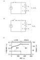
まず、充電方法の1つとしてCC充電について説明する。CC充電は、充電期間のすべてで一定の電流を二次電池に流し、所定の電圧になったときに充電を停止する充電方法である。二次電池を、図3(A)に示すように内部抵抗Rと二次電池容量Cの等価回路と仮定する。この場合、二次電池電圧VBは、内部抵抗Rにかかる電圧VRと二次電池容量Cにかかる電圧VCの和である。
≪CC charging≫
First, CC charging will be described as one of the charging methods. CC charging is a charging method in which a constant current is passed through a secondary battery during the entire charging period, and charging is stopped when a predetermined voltage is reached. It is assumed that the secondary battery is an equivalent circuit of the internal resistance R and the secondary battery capacity C as shown in FIG. 3 (A). In this case, the secondary battery voltage V B is the sum of the voltage V C applied to the voltage V R and the secondary battery capacity C according to the internal resistance R.
CC充電を行っている間は、図3(A)に示すように、スイッチがオンになり、一定の電流Iが二次電池に流れる。この間、電流Iが一定であるため、VR=R×Iのオームの法則により、内部抵抗Rにかかる電圧VRも一定である。一方、二次電池容量Cにかかる電圧VCは、時間の経過とともに上昇する。そのため、二次電池電圧VBは、時間の経過とともに上昇する。 During CC charging, as shown in FIG. 3A, the switch is turned on and a constant current I flows through the secondary battery. During this time, since a current I is constant, the Ohm's law V R = R × I, a voltage V R is also constant according to the internal resistance R. On the other hand, the voltage V C applied to the secondary battery capacity C increases with time. Therefore, the secondary battery voltage V B rises with the passage of time.
そして二次電池電圧VBが所定の電圧、例えば4.3Vになったときに、充電を停止する。CC充電を停止すると、図3(B)に示すように、スイッチがオフになり、電流I=0となる。そのため、内部抵抗Rにかかる電圧VRが0Vとなる。そのため、内部抵抗Rでの電圧降下がなくなった分、二次電池電圧VBが下降する。 Then, when the secondary battery voltage V B reaches a predetermined voltage, for example, 4.3 V, charging is stopped. When the CC charging is stopped, as shown in FIG. 3B, the switch is turned off and the current I = 0. Therefore, the voltage V R applied to the internal resistance R becomes 0V. Therefore, the secondary battery voltage V B drops by the amount that the voltage drop in the internal resistance R disappears.
CC充電を行っている間と、CC充電を停止してからの、二次電池電圧VBと充電電流の例を図3(C)に示す。CC充電を行っている間は上昇していた二次電池電圧VBが、CC充電を停止してから若干低下する様子が示されている。 FIG. 3 (C) shows an example of the secondary battery voltage V B and the charging current during CC charging and after CC charging is stopped. It is shown that the secondary battery voltage V B , which had been rising during CC charging, decreased slightly after CC charging was stopped.
≪CCCV充電≫
次に、上記と異なる充電方法であるCCCV充電について説明する。CCCV充電は、まずCC充電にて所定の電圧まで充電を行い、その後CV(定電圧)充電にて流れる電流が少なくなるまで、具体的には終止電流値になるまで充電を行う充電方法である。
≪CCCV charging≫
Next, CCCV charging, which is a charging method different from the above, will be described. CCCV charging is a charging method in which first charging is performed to a predetermined voltage by CC charging, and then charging is performed until the current flowing by CV (constant voltage) charging decreases, specifically, until the final current value is reached. ..
CC充電を行っている間は、図4(A)に示すように、定電流電源のスイッチがオン、定電圧電源のスイッチがオフになり、一定の電流Iが二次電池に流れる。この間、電流Iが一定であるため、VR=R×Iのオームの法則により、内部抵抗Rにかかる電圧VRも一定である。一方、二次電池容量Cにかかる電圧VCは、時間の経過とともに上昇する。そのため、二次電池電圧VBは、時間の経過とともに上昇する。 During CC charging, as shown in FIG. 4A, the constant current power supply switch is turned on, the constant voltage power supply switch is turned off, and a constant current I flows through the secondary battery. During this time, since a current I is constant, the Ohm's law V R = R × I, a voltage V R is also constant according to the internal resistance R. On the other hand, the voltage V C applied to the secondary battery capacity C increases with time. Therefore, the secondary battery voltage V B rises with the passage of time.
そして二次電池電圧VBが所定の電圧、例えば4.3Vになったときに、CC充電からCV充電に切り替える。CV充電を行っている間は、図4(B)に示すように、定電圧電源のスイッチがオン、定電流電源のスイッチがオフになり、二次電池電圧VBが一定となる。一方、二次電池容量Cにかかる電圧VCは、時間の経過とともに上昇する。VB=VR+VCであるため、内部抵抗Rにかかる電圧VRは、時間の経過とともに小さくなる。内部抵抗Rにかかる電圧VRが小さくなるに従い、VR=R×Iのオームの法則により、二次電池に流れる電流Iも小さくなる。 Then, when the secondary battery voltage V B reaches a predetermined voltage, for example, 4.3 V, the CC charge is switched to the CV charge. During CV charging, as shown in FIG. 4B, the constant voltage power supply switch is turned on, the constant current power supply switch is turned off, and the secondary battery voltage V B becomes constant. On the other hand, the voltage V C applied to the secondary battery capacity C increases with time. Because it is V B = V R + V C , the voltage V R applied to the internal resistance R becomes smaller with time. According voltage V R becomes smaller according to the internal resistance R, by Ohm's law of V R = R × I, also decreases the current I flowing through the secondary battery.
そして二次電池に流れる電流Iが所定の電流、例えば0.01C相当の電流となったとき、充電を停止する。CCCV充電を停止すると、図4(C)に示すように、全てのスイッチがオフになり、電流I=0となる。そのため、内部抵抗Rにかかる電圧VRが0Vとなる。しかし、CV充電により内部抵抗Rにかかる電圧VRが十分に小さくなっているため、内部抵抗Rでの電圧降下がなくなっても、二次電池電圧VBはほとんど降下しない。 Then, when the current I flowing through the secondary battery reaches a predetermined current, for example, a current equivalent to 0.01C, charging is stopped. When the CCCV charging is stopped, as shown in FIG. 4C, all the switches are turned off and the current I = 0. Therefore, the voltage V R applied to the internal resistance R becomes 0V. However, since the voltage V R applied to the internal resistance R by CV charging is sufficiently small, even run out of the voltage drop at the internal resistance R, the secondary battery voltage V B is hardly lowered.
CCCV充電を行っている間と、CCCV充電を停止してからの、二次電池電圧VBと充電電流の例を図4(D)に示す。CCCV充電を停止しても、二次電池電圧VBがほとんど降下しない様子が示されている。 FIG. 4 (D) shows an example of the secondary battery voltage V B and the charging current during the CCCV charging and after the CCCV charging is stopped. It is shown that the secondary battery voltage V B hardly drops even when the CCCV charging is stopped.
≪CC放電≫
次に、放電方法の1つであるCC放電について説明する。CC放電は、放電期間のすべてで一定の電流を二次電池から流し、二次電池電圧VBが所定の電圧、例えば2.5Vになったときに放電を停止する放電方法である。
≪CC discharge≫
Next, CC discharge, which is one of the discharge methods, will be described. CC discharge is a discharge method in which a constant current is passed from a secondary battery during the entire discharge period, and the discharge is stopped when the secondary battery voltage V B reaches a predetermined voltage, for example, 2.5 V.
CC放電を行っている間の二次電池電圧VBと放電電流の例を図5に示す。放電が進むに従い、二次電池電圧VBが降下していく様子が示されている。 An example of the secondary battery voltage V B and the discharge current during CC discharge is shown in FIG. It is shown that the secondary battery voltage V B drops as the discharge progresses.
次に、放電レート及び充電レートについて説明する。放電レートとは、電池容量に対する放電時の電流の相対的な比率であり、単位Cで表される。定格容量X(Ah)の電池において、1C相当の電流は、X(A)である。2X(A)の電流で放電させた場合は、2Cで放電させたといい、X/5(A)の電流で放電させた場合は、0.2Cで放電させたという。また、充電レートも同様であり、2X(A)の電流で充電させた場合は、2Cで充電させたといい、X/5(A)の電流で充電させた場合は、0.2Cで充電させたという。 Next, the discharge rate and the charge rate will be described. The discharge rate is a relative ratio of the current at the time of discharge to the battery capacity, and is expressed in the unit C. In a battery having a rated capacity of X (Ah), the current corresponding to 1C is X (A). When discharged with a current of 2X (A), it is said to be discharged at 2C, and when discharged with a current of X / 5 (A), it is said to be discharged at 0.2C. The charging rate is also the same. When charged with a current of 2X (A), it is said to be charged with 2C, and when charged with a current of X / 5 (A), it is charged with 0.2C. It is said that
(実施の形態3)
本実施の形態では、本発明の一態様である二次電池を電子機器に実装する例について説明する。
(Embodiment 3)
In the present embodiment, an example of mounting the secondary battery, which is one aspect of the present invention, in an electronic device will be described.
日用電子機器に二次電池として本発明の一態様の二次電池を用いることで、長寿命な製品を提供できる。例えば、日用電子機器として、電動歯ブラシ、電気シェーバー、電動美容機器などが挙げられ、それらの製品の二次電池としては、使用者の持ちやすさを考え、形状をスティック状とし、小型、軽量、且つ、大容量の二次電池が望まれている。 By using the secondary battery of one aspect of the present invention as the secondary battery in the daily electronic device, a product having a long life can be provided. For example, daily electronic devices include electric toothbrushes, electric shavers, electric beauty devices, etc., and the secondary batteries of these products are compact and lightweight with a stick-shaped shape in consideration of user-friendliness. Moreover, a large-capacity secondary battery is desired.
図6(A)および図6(B)に、2つ折り可能なタブレット型端末の一例を示す。図6(A)および図6(B)に示すタブレット型端末9600は、筐体9630a、筐体9630b、筐体9630aと筐体9630bを接続する可動部9640、表示部9631aと表示部9631bを有する表示部9631、表示モード切り替えスイッチ9626、電源スイッチ9627、省電力モード切り替えスイッチ9625、留め具9629、操作スイッチ9628、を有する。表示部9631には、可撓性を有するパネルを用いることで、より広い表示部を有するタブレット端末とすることができる。図6(A)は、タブレット型端末9600を開いた状態を示し、図6(B)は、タブレット型端末9600を閉じた状態を示している。
6 (A) and 6 (B) show an example of a tablet terminal that can be folded in half. The
また、タブレット型端末9600は、筐体9630aおよび筐体9630bの内部に蓄電体9635を有する。蓄電体9635は、可動部9640を通り、筐体9630aと筐体9630bに渡って設けられている。
Further, the
表示部9631aは、一部をタッチパネルの領域9632aとすることができ、表示された操作キー9638にふれることでデータ入力をすることができる。なお、表示部9631aにおいては、一例として半分の領域が表示のみの機能を有する構成、もう半分の領域がタッチパネルの機能を有する構成を示しているが該構成に限定されない。表示部9631aの全ての領域がタッチパネルの機能を有する構成としても良い。例えば、表示部9631aの全面をキーボードボタン表示させてタッチパネルとし、表示部9631bを表示画面として用いることができる。 A part of the display unit 9631a can be a touch panel area 9632a, and data can be input by touching the displayed operation key 9638. The display unit 9631a shows, for example, a configuration in which half of the area has a display-only function and the other half of the area has a touch panel function, but the configuration is not limited to this. The entire area of the display unit 9631a may have a touch panel function. For example, the entire surface of the display unit 9631a can be displayed as a keyboard button to form a touch panel, and the display unit 9631b can be used as a display screen.
また、表示部9631bにおいても表示部9631aと同様に、表示部9631bの一部をタッチパネルの領域9632bとすることができる。また、タッチパネルのキーボード表示切り替えボタン9639が表示されている位置に指やスタイラスなどでふれることで表示部9631bにキーボードボタン表示することができる。 Further, in the display unit 9631b as well, a part of the display unit 9631b can be a touch panel area 9632b, similarly to the display unit 9631a. Further, the keyboard button can be displayed on the display unit 9631b by touching the position where the keyboard display switching button 9639 on the touch panel is displayed with a finger or a stylus.
また、タッチパネルの領域9632aとタッチパネルの領域9632bに対して同時にタッチ入力することもできる。 Further, touch input can be simultaneously performed on the touch panel area 9632a and the touch panel area 9632b.
また、表示モード切り替えスイッチ9626は、縦表示又は横表示などの表示の向きを切り替え、白黒表示やカラー表示の切り替えなどを選択できる。省電力モード切り替えスイッチ9625は、タブレット型端末9600に内蔵している光センサで検出される使用時の外光の光量に応じて表示の輝度を最適なものとすることができる。タブレット型端末は光センサだけでなく、ジャイロ、加速度センサ等の傾きを検出するセンサなどの他の検出装置を内蔵させてもよい。
Further, the display
また、図6(A)では表示部9631bと表示部9631aの表示面積が同じ例を示しているが特に限定されず、一方のサイズともう一方のサイズが異なっていてもよく、表示の品質も異なっていてもよい。例えば一方が他方よりも高精細な表示を行える表示パネルとしてもよい。 Further, FIG. 6A shows an example in which the display areas of the display unit 9631b and the display unit 9631a are the same, but the display area is not particularly limited, and one size and the other size may be different, and the display quality is also good. It may be different. For example, one may be a display panel capable of displaying a higher definition than the other.
図6(B)は、閉じた状態であり、タブレット型端末は、筐体9630、太陽電池9633、DCDCコンバータ9636を含む充放電制御回路9634有する。また、蓄電体9635として、本発明の一態様に係る蓄電体を用いる。
FIG. 6B shows a closed state, and the tablet terminal has a charge /
なお、タブレット型端末9600は2つ折り可能なため、未使用時に筐体9630aおよび筐体9630bを重ね合せるように折りたたむことができる。折りたたむことにより、表示部9631a、表示部9631bを保護できるため、タブレット型端末9600の耐久性を高めることができる。また、本発明の一態様の二次電池を用いた蓄電体9635は高容量、良好なサイクル特性を有するため、長期間に渡って長時間の使用ができるタブレット型端末9600を提供できる。
Since the
また、この他にも図6(A)および図6(B)に示したタブレット型端末は、様々な情報(静止画、動画、テキスト画像など)を表示する機能、カレンダー、日付又は時刻などを表示部に表示する機能、表示部に表示した情報をタッチ入力操作又は編集するタッチ入力機能、様々なソフトウェア(プログラム)によって処理を制御する機能、等を有することができる。 In addition to this, the tablet-type terminal shown in FIGS. 6 (A) and 6 (B) has a function of displaying various information (still images, moving images, text images, etc.), a calendar, a date, a time, and the like. It can have a function of displaying on a display unit, a touch input function of performing a touch input operation or editing information displayed on the display unit, a function of controlling processing by various software (programs), and the like.
タブレット型端末の表面に装着された太陽電池9633によって、電力をタッチパネル、表示部、又は映像信号処理部等に供給することができる。なお、太陽電池9633は、筐体9630の片面又は両面に設けることができ、蓄電体9635の充電を効率的に行う構成とすることができる。なお蓄電体9635としては、リチウムイオン電池を用いると、小型化を図れる等の利点がある。
Electric power can be supplied to a touch panel, a display unit, a video signal processing unit, or the like by a
また、図6(B)に示す充放電制御回路9634の構成、および動作について図6(C)にブロック図を示し説明する。図6(C)には、太陽電池9633、蓄電体9635、DCDCコンバータ9636、コンバータ9637、スイッチSW1乃至SW3、表示部9631について示しており、蓄電体9635、DCDCコンバータ9636、コンバータ9637、スイッチSW1乃至SW3が、図6(B)に示す充放電制御回路9634に対応する箇所となる。
Further, the configuration and operation of the charge /
まず外光により太陽電池9633により発電がされる場合の動作の例について説明する。太陽電池で発電した電力は、蓄電体9635を充電するための電圧となるようDCDCコンバータ9636で昇圧又は降圧がなされる。そして、表示部9631の動作に太陽電池9633からの電力が用いられる際にはスイッチSW1をオンにし、コンバータ9637で表示部9631に必要な電圧に昇圧又は降圧をすることとなる。また、表示部9631での表示を行わない際には、SW1をオフにし、SW2をオンにして蓄電体9635の充電を行う構成とすればよい。
First, an example of operation when power is generated by the
なお太陽電池9633については、発電手段の一例として示したが、特に限定されず、圧電素子(ピエゾ素子)や熱電変換素子(ペルティエ素子)などの他の発電手段による蓄電体9635の充電を行う構成であってもよい。例えば、無線(非接触)で電力を送受信して充電する無接点電力伝送モジュールや、また他の充電手段を組み合わせて行う構成としてもよい。
The
図7に、他の電子機器の例を示す。図7において、表示装置8000は、本発明の一態様に係る二次電池8004を用いた電子機器の一例である。具体的に、表示装置8000は、TV放送受信用の表示装置に相当し、筐体8001、表示部8002、スピーカ部8003、二次電池8004等を有する。本発明の一態様に係る二次電池8004は、筐体8001の内部に設けられている。表示装置8000は、商用電源から電力の供給を受けることもできるし、二次電池8004に蓄積された電力を用いることもできる。よって、停電などにより商用電源から電力の供給が受けられない時でも、本発明の一態様に係る二次電池8004を無停電電源として用いることで、表示装置8000の利用が可能となる。
FIG. 7 shows an example of another electronic device. In FIG. 7, the
表示部8002には、液晶表示装置、有機EL素子などの発光素子を各画素に備えた発光装置、電気泳動表示装置、DMD(Digital Micromirror Device)、PDP(Plasma Display Panel)、FED(Field Emission Display)などの、半導体表示装置を用いることができる。
The
なお、表示装置には、TV放送受信用の他、パーソナルコンピュータ用、広告表示用など、全ての情報表示用表示装置が含まれる。 The display device includes all information display devices such as those for receiving TV broadcasts, those for personal computers, and those for displaying advertisements.
図7において、据え付け型の照明装置8100は、本発明の一態様に係る二次電池8103を用いた電子機器の一例である。具体的に、照明装置8100は、筐体8101、光源8102、二次電池8103等を有する。図7では、二次電池8103が、筐体8101及び光源8102が据え付けられた天井8104の内部に設けられている場合を例示しているが、二次電池8103は、筐体8101の内部に設けられていても良い。照明装置8100は、商用電源から電力の供給を受けることもできるし、二次電池8103に蓄積された電力を用いることもできる。よって、停電などにより商用電源から電力の供給が受けられない時でも、本発明の一態様に係る二次電池8103を無停電電源として用いることで、照明装置8100の利用が可能となる。
In FIG. 7, the
なお、図7では天井8104に設けられた据え付け型の照明装置8100を例示しているが、本発明の一態様に係る二次電池は、天井8104以外、例えば側壁8105、床8106、窓8107等に設けられた据え付け型の照明装置に用いることもできるし、卓上型の照明装置などに用いることもできる。
Although FIG. 7 illustrates a
また、光源8102には、電力を利用して人工的に光を得る人工光源を用いることができる。具体的には、白熱電球、蛍光灯などの放電ランプ、LEDや有機EL素子などの発光素子が、上記人工光源の一例として挙げられる。
Further, as the
図7において、室内機8200及び室外機8204を有するエアコンディショナーは、本発明の一態様に係る二次電池8203を用いた電子機器の一例である。具体的に、室内機8200は、筐体8201、送風口8202、二次電池8203等を有する。図7では、二次電池8203が、室内機8200に設けられている場合を例示しているが、二次電池8203は室外機8204に設けられていても良い。或いは、室内機8200と室外機8204の両方に、二次電池8203が設けられていても良い。エアコンディショナーは、商用電源から電力の供給を受けることもできるし、二次電池8203に蓄積された電力を用いることもできる。特に、室内機8200と室外機8204の両方に二次電池8203が設けられている場合、停電などにより商用電源から電力の供給が受けられない時でも、本発明の一態様に係る二次電池8203を無停電電源として用いることで、エアコンディショナーの利用が可能となる。
In FIG. 7, the air conditioner having the
なお、図7では、室内機と室外機で構成されるセパレート型のエアコンディショナーを例示しているが、室内機の機能と室外機の機能とを1つの筐体に有する一体型のエアコンディショナーに、本発明の一態様に係る二次電池を用いることもできる。 Although FIG. 7 illustrates a separate type air conditioner composed of an indoor unit and an outdoor unit, the integrated air conditioner having the functions of the indoor unit and the outdoor unit in one housing may be used. , A secondary battery according to one aspect of the present invention can also be used.
図7において、電気冷凍冷蔵庫8300は、本発明の一態様に係る二次電池8304を用いた電子機器の一例である。具体的に、電気冷凍冷蔵庫8300は、筐体8301、冷蔵室用扉8302、冷凍室用扉8303、二次電池8304等を有する。図7では、二次電池8304が、筐体8301の内部に設けられている。電気冷凍冷蔵庫8300は、商用電源から電力の供給を受けることもできるし、二次電池8304に蓄積された電力を用いることもできる。よって、停電などにより商用電源から電力の供給が受けられない時でも、本発明の一態様に係る二次電池8304を無停電電源として用いることで、電気冷凍冷蔵庫8300の利用が可能となる。
In FIG. 7, the electric refrigerator /
なお、上述した電子機器のうち、電子レンジ等の高周波加熱装置、電気炊飯器などの電子機器は、短時間で高い電力を必要とする。よって、商用電源では賄いきれない電力を補助するための補助電源として、本発明の一態様に係る二次電池を用いることで、電子機器の使用時に商用電源のブレーカーが落ちるのを防ぐことができる。 Among the above-mentioned electronic devices, high-frequency heating devices such as microwave ovens and electronic devices such as electric rice cookers require high electric power in a short time. Therefore, by using the secondary battery according to one aspect of the present invention as an auxiliary power source for assisting the electric power that cannot be covered by the commercial power source, it is possible to prevent the breaker of the commercial power source from being tripped when the electronic device is used. ..
また、電子機器が使用されない時間帯、特に、商用電源の供給元が供給可能な総電力量のうち、実際に使用される電力量の割合(電力使用率と呼ぶ)が低い時間帯において、二次電池に電力を蓄えておくことで、上記時間帯以外において電力使用率が高まるのを抑えることができる。例えば、電気冷凍冷蔵庫8300の場合、気温が低く、冷蔵室用扉8302、冷凍室用扉8303の開閉が行われない夜間において、二次電池8304に電力を蓄える。そして、気温が高くなり、冷蔵室用扉8302、冷凍室用扉8303の開閉が行われる昼間において、二次電池8304を補助電源として用いることで、昼間の電力使用率を低く抑えることができる。
In addition, during times when electronic devices are not used, especially during times when the ratio of the amount of power actually used (called the power usage rate) to the total amount of power that can be supplied by the source of commercial power is low. By storing the electric power in the next battery, it is possible to suppress the increase in the electric power usage rate other than the above time zone. For example, in the case of the electric refrigerator-
本発明の一態様により、二次電池のサイクル特性が良好となり、信頼性を向上させることができる。また、本発明の一態様によれば、高容量の二次電池とすることができ、よって、二次電池の特性を向上することができ、よって、二次電池自体を小型軽量化することができる。そのため本発明の一態様である二次電池を、本実施の形態で説明した電子機器に搭載することで、より長寿命で、より軽量な電子機器とすることができる。本実施の形態は、他の実施の形態と適宜組み合わせて実施することが可能である。 According to one aspect of the present invention, the cycle characteristics of the secondary battery can be improved and the reliability can be improved. Further, according to one aspect of the present invention, it is possible to obtain a high-capacity secondary battery, thereby improving the characteristics of the secondary battery, and thus reducing the size and weight of the secondary battery itself. it can. Therefore, by mounting the secondary battery, which is one aspect of the present invention, in the electronic device described in the present embodiment, it is possible to obtain an electronic device having a longer life and a lighter weight. This embodiment can be implemented in combination with other embodiments as appropriate.
(実施の形態4)
本実施の形態では、車両に本発明の一態様である二次電池を搭載する例を示す。
(Embodiment 4)
In the present embodiment, an example in which a secondary battery, which is one aspect of the present invention, is mounted on a vehicle is shown.
二次電池を車両に搭載すると、ハイブリッド車(HEV)、電気自動車(EV)、又はプラグインハイブリッド車(PHEV)等の次世代クリーンエネルギー自動車を実現できる。 When a secondary battery is mounted on a vehicle, a next-generation clean energy vehicle such as a hybrid electric vehicle (HEV), an electric vehicle (EV), or a plug-in hybrid vehicle (PHEV) can be realized.
図8において、本発明の一態様である二次電池を用いた車両を例示する。図8(A)に示す自動車8400は、走行のための動力源として電気モーターを用いる電気自動車である。または、走行のための動力源として電気モーターとエンジンを適宜選択して用いることが可能なハイブリッド自動車である。本発明の一態様を用いることで、航続距離の長い車両を実現することができる。また、自動車8400は二次電池を有する。二次電池は、車内の床部分に対して、複数の二次電池のモジュールを並べて使用すればよい。また、二次電池を複数組み合わせた電池パックを車内の床部分に対して設置してもよい。二次電池は電気モーター8406を駆動するだけでなく、ヘッドライト8401やルームライト(図示せず)などの発光装置に電力を供給することができる。
FIG. 8 illustrates a vehicle using a secondary battery, which is one aspect of the present invention. The
また、二次電池は、自動車8400が有するスピードメーター、タコメーターなどの表示装置に電力を供給することができる。また、二次電池は、自動車8400が有するナビゲーションシステムなどの半導体装置に電力を供給することができる。
In addition, the secondary battery can supply electric power to display devices such as a speedometer and a tachometer included in the
図8(B)に示す自動車8500は、自動車8500が有する二次電池にプラグイン方式や非接触給電方式等により外部の充電設備から電力供給を受けて、充電することができる。図8(B)に、地上設置型の充電装置8021から自動車8500に搭載された二次電池8024に、ケーブル8022を介して充電を行っている状態を示す。充電に際しては、充電方法やコネクターの規格等はCHAdeMO(登録商標)やコンボ等の所定の方式で適宜行えばよい。充電装置8021は、商用施設に設けられた充電ステーションでもよく、また家庭の電源であってもよい。例えば、プラグイン技術によって、外部からの電力供給により自動車8500に搭載された二次電池8024を充電することができる。充電は、ACDCコンバータ等の変換装置を介して、交流電力を直流電力に変換して行うことができる。
The
また、図示しないが、受電装置を車両に搭載し、地上の送電装置から電力を非接触で供給して充電することもできる。この非接触給電方式の場合には、道路や外壁に送電装置を組み込むことで、停車中に限らず走行中に充電を行うこともできる。また、この非接触給電の方式を利用して、車両どうしで電力の送受信を行ってもよい。さらに、車両の外装部に太陽電池を設け、停車時や走行時に二次電池の充電を行ってもよい。このような非接触での電力の供給には、電磁誘導方式や磁界共鳴方式を用いることができる。 Further, although not shown, it is also possible to mount the power receiving device on the vehicle and supply electric power from the ground power transmission device in a non-contact manner to charge the vehicle. In the case of this non-contact power supply system, by incorporating a power transmission device on the road or the outer wall, it is possible to charge the battery not only while the vehicle is stopped but also while the vehicle is running. Further, the non-contact power feeding method may be used to transmit and receive electric power between vehicles. Further, a solar cell may be provided on the exterior of the vehicle to charge the secondary battery when the vehicle is stopped or running. An electromagnetic induction method or a magnetic field resonance method can be used for such non-contact power supply.
また、図8(C)は、本発明の一態様の二次電池を用いた二輪車の一例である。図8(C)に示すスクータ8600は、二次電池8602、サイドミラー8601、方向指示灯8603を備える。二次電池8602は、方向指示灯8603に電気を供給することができる。
Further, FIG. 8C is an example of a two-wheeled vehicle using the secondary battery of one aspect of the present invention. The
また、図8(C)に示すスクータ8600は、座席下収納8604に、二次電池8602を収納することができる。二次電池8602は、座席下収納8604が小型であっても、座席下収納8604に収納することができる。二次電池8602は、取り外し可能となっており、充電時には二次電池8602を屋内に持って運び、充電し、走行する前に収納すればよい。
Further, in the
本発明の一態様によれば、二次電池のサイクル特性が良好となり、二次電池の容量を大きくすることができる。よって、二次電池自体を小型軽量化することができる。二次電池自体を小型軽量化できれば、車両の軽量化に寄与するため、航続距離を向上させることができる。また、車両に搭載した二次電池を車両以外の電力供給源として用いることもできる。 According to one aspect of the present invention, the cycle characteristics of the secondary battery are improved, and the capacity of the secondary battery can be increased. Therefore, the secondary battery itself can be made smaller and lighter. If the secondary battery itself can be made smaller and lighter, it will contribute to the weight reduction of the vehicle, and thus the cruising range can be improved. Further, the secondary battery mounted on the vehicle can also be used as a power supply source other than the vehicle.
本実施の形態は、他の実施の形態と適宜組み合わせて実施することが可能である。 This embodiment can be implemented in combination with other embodiments as appropriate.
本実施例では、本発明の一態様である正極活物質を含む正極を作製し、該正極活物質周辺について断面を観察した結果について説明する。また、該正極活物質を含む正極を用いた二次電池の特性を評価した結果について説明する。 In this embodiment, the result of producing a positive electrode containing the positive electrode active material, which is one aspect of the present invention, and observing the cross section around the positive electrode active material will be described. In addition, the result of evaluating the characteristics of the secondary battery using the positive electrode containing the positive electrode active material will be described.
[正極活物質の作製]
≪サンプル01≫
本実施例では、サンプルの正極活物質として、第1の領域が有するリチウムと第1の遷移金属の複合酸化物として、コバルト酸リチウムを有し、第2の領域が有する、第2の遷移金属の酸化物として、チタン酸リチウムを有し、第3の領域が有する、典型元素の酸化物として、酸化マグネシウムを有するものを作製した。
[Preparation of positive electrode active material]
≪Sample 01≫
In this example, the positive electrode active material of the sample has lithium cobalt oxide as a composite oxide of lithium possessed by the first region and the first transition metal, and the second transition metal possessed by the second region. As an oxide of the above, lithium titanate was prepared, and as an oxide of a main group element possessed by the third region, magnesium oxide was prepared.
本実施例では、出発原料としてコバルト酸リチウム粒子(日本化学工業株式会社製、商品名:C−20F)を用いた。そのため本実施例では、実施の形態1で説明したステップ12およびステップ13を省略した。なお上記コバルト酸リチウム粒子は、粒径が約20μmであり、XPSで分析可能な領域にフッ素、マグネシウム、カルシウム、ナトリウム、シリコン、硫黄、リンを含むコバルト酸リチウム粒子である。 In this example, lithium cobalt oxide particles (manufactured by Nippon Chemical Industrial Co., Ltd., trade name: C-20F) were used as a starting material. Therefore, in this embodiment, steps 12 and 13 described in the first embodiment are omitted. The lithium cobalt oxide particles have a particle size of about 20 μm and contain fluorine, magnesium, calcium, sodium, silicon, sulfur, and phosphorus in a region that can be analyzed by XPS.
次に、ステップ14としてマグネシウムとフッ素を含むコバルト酸リチウム粒子にゾルゲル法によりチタンを含む材料を被覆した。具体的には、イソプロパノールにTTIPを溶解し、TTIPのイソプロパノール溶液を作製した。そして該溶液に、コバルト酸リチウム粒子を混合した。TTIPがマグネシウムとフッ素を含むコバルト酸リチウムに対して0.04ml/gとなるように混合した。 Next, as step 14, lithium cobalt oxide particles containing magnesium and fluorine were coated with a material containing titanium by a sol-gel method. Specifically, TTIP was dissolved in isopropanol to prepare an isopropanol solution of TTIP. Then, lithium cobalt oxide particles were mixed with the solution. The TTIP was mixed with lithium cobalt oxide containing magnesium and fluorine so as to be 0.04 ml / g.
上記混合液を、マグネチックスターラーで4時間、25℃、湿度90%RHの条件下で撹拌した。この処理により、雰囲気中の水とTTIPで加水分解および重縮合反応を起こさせ、マグネシウムとフッ素を有するコバルト酸リチウム粒子の表面に、チタンを含む層を形成させた。 The mixture was stirred with a magnetic stirrer for 4 hours at 25 ° C. and 90% humidity RH. By this treatment, hydrolysis and polycondensation reaction were caused by TTIP with water in the atmosphere, and a layer containing titanium was formed on the surface of lithium cobalt oxide particles having magnesium and fluorine.
上記の処理を終えた混合液を遠心分離し、溶媒の上澄みを除去して残渣を回収した。遠心分離条件は3000rpm、1分とした。 The mixed solution after the above treatment was centrifuged, the supernatant of the solvent was removed, and the residue was recovered. The centrifugation condition was 3000 rpm for 1 minute.
回収した残渣を、70℃で1時間、真空乾燥した。 The recovered residue was vacuum dried at 70 ° C. for 1 hour.
次に、チタンを有する材料で被覆されたコバルト酸リチウム粒子を加熱した。マッフル炉を用いて、酸素の流量は10L/minとし、800℃(昇温200℃/時間)、保持時間2時間で加熱した。
Next, the lithium cobalt oxide particles coated with a material having titanium were heated. Using a muffle furnace, the flow rate of oxygen was set to 10 L / min, and heating was performed at 800 ° C. (
次に、加熱された粒子を室温まで冷却した。保持温度から室温までの降温時間は10〜15時間とした。その後、解砕処理を行った。解砕処理は、ふるいにかけることにより行い、ふるいは目開きが53μmのものを用いた。 The heated particles were then cooled to room temperature. The temperature lowering time from the holding temperature to room temperature was 10 to 15 hours. Then, crushing treatment was performed. The crushing treatment was carried out by sieving, and a sieve having an opening of 53 μm was used.
最後に冷却された粒子を回収し、サンプル01の正極活物質を得た。 Finally, the cooled particles were collected to obtain the positive electrode active material of Sample 01.
[二次電池の作製]
上記で作製したサンプル01の正極活物質を用いた、CR2032タイプ(直径20mm高さ3.2mm)のコイン型の二次電池を作製した。
[Making secondary batteries]
A CR2032 type (
正極には、正極活物質(LCO)と、カーボンナノチューブ(VGCF(登録商標))と、ポリフッ化ビニリデン(PVDF)をLCO:カーボンナノチューブ:PVDF=96:2:2(重量比)で混合したスラリーを集電体(アルミニウム箔)に塗工したものを用いた。断面SEM写真を図9(A)及び図9(B)に示す。なお、サンプル01は同じサンプルを3つ作製し、プレス圧は、プレスなし、210kN/m、713kN/m、1216kN/m、1467kN/mとそれぞれ条件を振り、電極密度を測定した。プレス温度は120℃とした。なお、本実施例では、正極において正極活物質と、炭素繊維と、ポリフッ化ビニリデンの重量比を96:2:2とする例を示したが特に限定されず、例えば、重量比を95:3:2としてもよい。 For the positive electrode, a slurry in which a positive electrode active material (LCO), carbon nanotubes (VGCF (registered trademark)), and polyvinylidene fluoride (PVDF) are mixed at LCO: carbon nanotubes: PVDF = 96: 2: 2 (weight ratio). Was applied to the current collector (aluminum foil). Cross-sectional SEM photographs are shown in FIGS. 9 (A) and 9 (B). For sample 01, three identical samples were prepared, and the press pressures were 210 kN / m, 713 kN / m, 1216 kN / m, and 1467 kN / m, respectively, and the electrode density was measured. The press temperature was 120 ° C. In this embodiment, an example in which the weight ratio of the positive electrode active material, the carbon fiber, and polyvinylidene fluoride is 96: 2: 2 is shown in the positive electrode, but the weight ratio is not particularly limited, and for example, the weight ratio is 95: 3. : May be 2.
電極密度を測定した結果を表1に示す。 The results of measuring the electrode density are shown in Table 1.

表1に示したように、1216kN/m、1467kN/mの2条件で得られた正極活物質層の電極密度は、4.6g/cm3となった。 As shown in Table 1, the electrode density of the positive electrode active material layer obtained under the two conditions of 1216 kN / m and 1467 kN / m was 4.6 g / cm 3 .
用いた気相成長炭素繊維(VGCF(登録商標):Vapor−Grown Carbon Fiber)の代表値は、繊維径150nm、繊維長10μm以上20μm以下、真密度2.1g/cm3、比表面積13m2/gである。なお、繊維径とは、SEMで観察して、二次元的に撮影された画像から繊維軸に対して垂直方向の断面を切断面とし、この切断面に外接する真円の径のことを指す。また、真密度とは、物質自身が占める体積だけを密度算定用の体積とする密度のことを指す。また、比表面積とは、対象物について単位質量あたりの表面積または単位体積あたりの表面積のことである。
Typical values of the vapor-grown carbon fiber (VGCF (registered trademark): Vapor-Grown Carbon Fiber) used are
対極にはリチウム金属を用いた。 Lithium metal was used as the counter electrode.
電解液が有する電解質には、1mol/Lの六フッ化リン酸リチウム(LiPF6)を用い、電解液には、エチレンカーボネート(EC)とジエチルカーボネート(DEC)がEC:DEC=3:7(体積比)、ビニレンカーボネート(VC)が2重量%で混合されたものを用いた。セパレータにはポリポロピレンを用いた。 1 mol / L lithium hexafluorophosphate (LiPF 6 ) was used as the electrolyte contained in the electrolytic solution, and ethylene carbonate (EC) and diethyl carbonate (DEC) were used as the electrolytic solution in EC: DEC = 3: 7 ( Volume ratio) and vinylene carbonate (VC) mixed in an amount of 2% by weight were used. Polyporopylene was used as the separator.
正極缶及び負極缶には、ステンレス(SUS)で形成されているものを用いた。 As the positive electrode can and the negative electrode can, those made of stainless steel (SUS) were used.
また、比較のため、カーボンナノチューブ(VGCF)に代えてABを用いたサンプル02を用意し、同じ工程で3つサンプルを作製し、プレス圧は、プレスなし(0kN/m)、210kN/m、713kN/m、1216kN/m、1467kN/mとそれぞれ条件を振った。1467kN/mの1条件でのみ4.0g/cm3が得られた。これらの結果からABのみを用いた場合、プレス圧を高くしても均一性よく電極密度4.0g/cm3を超え、電極密度4.2g/cm3以上となるような電極密度を得ることが困難である。 For comparison, sample 02 using AB instead of carbon nanotube (VGCF) was prepared, three samples were prepared in the same process, and the press pressure was no press (0 kN / m), 210 kN / m, and so on. The conditions were set to 713 kN / m, 1216 kN / m, and 1467 kN / m, respectively. 4.0 g / cm 3 was obtained only under one condition of 1467 kN / m. From these results, when only AB is used, the electrode density can be obtained so that the electrode density exceeds 4.0 g / cm 3 and the electrode density is 4.2 g / cm 3 or more with good uniformity even when the press pressure is increased. Is difficult.
また、電極密度の平均値でグラフを作成した結果を図10に示す。縦軸に電極密度、横軸にプレス圧力を示している。 Further, FIG. 10 shows the result of creating a graph with the average value of the electrode densities. The vertical axis shows the electrode density and the horizontal axis shows the press pressure.
[サイクル特性の評価]
次に、上記で作製したサンプル01(プレス圧条件:1467kN/mのサンプル)の二次電池の充放電特性の評価を行った。測定温度は45℃とした。充電は4.55V(CCCV,1C、カットオフ電流0.05C)、放電は3V(CC,1C)で、それぞれ100サイクル充放電を行った。サンプル01のサイクル試験の休止時間は1分とした。なお、ここでの1Cは、正極活物質重量あたりの電流値で160mAh/gとした。
[Evaluation of cycle characteristics]
Next, the charge / discharge characteristics of the secondary battery of the sample 01 (press pressure condition: 1467 kN / m sample) prepared above were evaluated. The measurement temperature was 45 ° C. Charging was 4.55V (CCCV, 1C, cutoff current 0.05C), and discharging was 3V (CC, 1C), each of which was charged and discharged for 100 cycles. The rest time of the cycle test of sample 01 was set to 1 minute. The current value of 1C here was 160 mAh / g per weight of the positive electrode active material.
図11は、サンプル01のサイクル試験結果である。休止時間を1分としてサイクル試験を行い、初回の放電容量は、211.6mAh/gであり、100回サイクル後の放電容量は、186.9mAh/gであった。図11に示すように、充放電サイクル100回目での充放電サイクルの容量維持率を88.3%に抑えることができ、良好であった。なお、サンプル01の充放電特性は、広いプラトーを有する良好な充放電特性が得られている。 FIG. 11 shows the cycle test result of sample 01. A cycle test was conducted with a rest time of 1 minute, and the initial discharge capacity was 211.6 mAh / g, and the discharge capacity after 100 cycles was 186.9 mAh / g. As shown in FIG. 11, the capacity retention rate of the charge / discharge cycle at the 100th charge / discharge cycle could be suppressed to 88.3%, which was good. As for the charge / discharge characteristics of the sample 01, good charge / discharge characteristics having a wide plateau are obtained.
100a:正極活物質
100b:正極活物質
100c:正極活物質
130:バインダ
131a、131b:炭素繊維
100a: Positive electrode
Claims (5)
前記正極は、正極活物質と、導電助剤と、を有し、
前記正極活物質は、リチウムと、コバルトと、酸素と、チタンと、マグネシウムと、フッ素と、を有し、
前記導電助剤は、比表面積が60m 2 /g未満である炭素繊維と、カーボンブラックと、を有する二次電池。 It has a positive electrode and a negative electrode,
The positive electrode has a positive electrode active material and a conductive auxiliary agent.
The positive electrode active material has lithium, cobalt, oxygen, titanium, magnesium, and fluorine.
The conductive auxiliary agent is a secondary battery having carbon fibers having a specific surface area of less than 60 m 2 / g and carbon black.
前記正極は、正極活物質と、導電助剤と、を有し、
前記正極活物質は、リチウムと、コバルトと、酸素と、チタンと、マグネシウムと、フッ素と、を有し、
前記導電助剤は、比表面積が60m 2 /g未満である炭素繊維と、カーボンブラックと、を有し、
前記正極の電極密度の平均値は4.0g/cm3以上である二次電池。 It has a positive electrode and a negative electrode,
The positive electrode has a positive electrode active material and a conductive auxiliary agent.
The positive electrode active material has lithium, cobalt, oxygen, titanium, magnesium, and fluorine.
The conductive auxiliary agent has carbon fibers having a specific surface area of less than 60 m 2 / g and carbon black.
A secondary battery in which the average value of the electrode densities of the positive electrodes is 4.0 g / cm 3 or more.
前記正極は、正極活物質と、導電助剤と、を有し、
前記正極活物質は、リチウムと、コバルトと、酸素と、チタンと、マグネシウムと、フッ素と、を有し、
前記導電助剤は、比表面積が60m 2 /g未満である炭素繊維と、カーボンブラックと、を有し、
充放電サイクルの測定において、100回目での充放電サイクルの低下率が15%未満である二次電池。 It has a positive electrode and a negative electrode,
The positive electrode has a positive electrode active material and a conductive auxiliary agent.
The positive electrode active material has lithium, cobalt, oxygen, titanium, magnesium, and fluorine.
The conductive auxiliary agent has carbon fibers having a specific surface area of less than 60 m 2 / g and carbon black.
A secondary battery in which the rate of decrease in the charge / discharge cycle at the 100th time is less than 15% in the measurement of the charge / discharge cycle.
前記正極は、正極活物質と、導電助剤と、を有し、
前記正極活物質は、リチウムと、コバルトと、酸素と、チタンと、マグネシウムと、フッ素と、を有し、
前記導電助剤は、比表面積が60m 2 /g未満である炭素繊維と、カーボンブラックと、を有し、
前記正極の電極密度の平均値は4.0g/cm3以上であり、
充放電サイクルの測定において、100回目での充放電サイクルの低下率が15%未満である二次電池。 It has a positive electrode and a negative electrode,
The positive electrode has a positive electrode active material and a conductive auxiliary agent.
The positive electrode active material has lithium, cobalt, oxygen, titanium, magnesium, and fluorine.
The conductive auxiliary agent has carbon fibers having a specific surface area of less than 60 m 2 / g and carbon black.
The average value of the electrode density of the positive electrode is 4.0 g / cm 3 or more.
A secondary battery in which the rate of decrease in the charge / discharge cycle at the 100th time is less than 15% in the measurement of the charge / discharge cycle.
前記炭素繊維はカーボンナノチューブである二次電池。 In any one of claims 1 to 4,
A secondary battery in which the carbon fibers are carbon nanotubes.
Priority Applications (3)
| Application Number | Priority Date | Filing Date | Title |
|---|---|---|---|
| JP2017124036A JP6885802B2 (en) | 2017-06-26 | 2017-06-26 | Secondary battery |
| JP2021081434A JP7135160B2 (en) | 2017-06-26 | 2021-05-13 | lithium ion secondary battery |
| JP2022137896A JP7371186B2 (en) | 2017-06-26 | 2022-08-31 | Positive electrode active material layer and secondary battery |
Applications Claiming Priority (1)
| Application Number | Priority Date | Filing Date | Title |
|---|---|---|---|
| JP2017124036A JP6885802B2 (en) | 2017-06-26 | 2017-06-26 | Secondary battery |
Related Child Applications (1)
| Application Number | Title | Priority Date | Filing Date |
|---|---|---|---|
| JP2021081434A Division JP7135160B2 (en) | 2017-06-26 | 2021-05-13 | lithium ion secondary battery |
Publications (3)
| Publication Number | Publication Date |
|---|---|
| JP2019009001A JP2019009001A (en) | 2019-01-17 |
| JP2019009001A5 JP2019009001A5 (en) | 2020-05-21 |
| JP6885802B2 true JP6885802B2 (en) | 2021-06-16 |
Family
ID=65029075
Family Applications (3)
| Application Number | Title | Priority Date | Filing Date |
|---|---|---|---|
| JP2017124036A Active JP6885802B2 (en) | 2017-06-26 | 2017-06-26 | Secondary battery |
| JP2021081434A Active JP7135160B2 (en) | 2017-06-26 | 2021-05-13 | lithium ion secondary battery |
| JP2022137896A Active JP7371186B2 (en) | 2017-06-26 | 2022-08-31 | Positive electrode active material layer and secondary battery |
Family Applications After (2)
| Application Number | Title | Priority Date | Filing Date |
|---|---|---|---|
| JP2021081434A Active JP7135160B2 (en) | 2017-06-26 | 2021-05-13 | lithium ion secondary battery |
| JP2022137896A Active JP7371186B2 (en) | 2017-06-26 | 2022-08-31 | Positive electrode active material layer and secondary battery |
Country Status (1)
| Country | Link |
|---|---|
| JP (3) | JP6885802B2 (en) |
Families Citing this family (3)
| Publication number | Priority date | Publication date | Assignee | Title |
|---|---|---|---|---|
| JP7782448B2 (en) | 2020-08-24 | 2025-12-09 | 株式会社Gsユアサ | Energy storage element |
| DE112022002815T5 (en) * | 2021-05-28 | 2024-03-07 | Semiconductor Energy Laboratory Co., Ltd. | Battery, electronic device, energy storage system and moving object |
| JP7697326B2 (en) * | 2021-09-09 | 2025-06-24 | トヨタ自動車株式会社 | Negative electrode layer |
Family Cites Families (6)
| Publication number | Priority date | Publication date | Assignee | Title |
|---|---|---|---|---|
| JP3695366B2 (en) * | 2001-03-21 | 2005-09-14 | 日亜化学工業株式会社 | Positive electrode active material for lithium ion secondary battery and method for producing the same |
| JP3930002B2 (en) * | 2003-07-28 | 2007-06-13 | 昭和電工株式会社 | High density electrode and battery using the electrode |
| FI20060951A7 (en) * | 2004-04-30 | 2006-10-27 | Seimi Chem Kk | Method for preparing a lithium-containing composite oxide for a positive electrode for a lithium battery |
| JP2010176996A (en) * | 2009-01-28 | 2010-08-12 | Sanyo Electric Co Ltd | Nonaqueous electrolyte secondary battery |
| JP5732351B2 (en) * | 2010-09-02 | 2015-06-10 | 日本化学工業株式会社 | Method for producing lithium cobalt oxide |
| WO2014017583A1 (en) * | 2012-07-26 | 2014-01-30 | Tdk株式会社 | Lithium ion secondary battery |
-
2017
- 2017-06-26 JP JP2017124036A patent/JP6885802B2/en active Active
-
2021
- 2021-05-13 JP JP2021081434A patent/JP7135160B2/en active Active
-
2022
- 2022-08-31 JP JP2022137896A patent/JP7371186B2/en active Active
Also Published As
| Publication number | Publication date |
|---|---|
| JP7135160B2 (en) | 2022-09-12 |
| JP2022169766A (en) | 2022-11-09 |
| JP2019009001A (en) | 2019-01-17 |
| JP2021120956A (en) | 2021-08-19 |
| JP7371186B2 (en) | 2023-10-30 |
Similar Documents
| Publication | Publication Date | Title |
|---|---|---|
| JP7337113B2 (en) | lithium ion secondary battery | |
| KR102637323B1 (en) | Positive electrode active material, method for manufacturing positive electrode active material, and secondary battery | |
| JP2020140954A (en) | Positive electrode active material, method for producing positive electrode active material, and secondary battery | |
| CN112201844A (en) | Manufacturing method of positive electrode active material and secondary battery | |
| JP6885724B2 (en) | Lithium-ion secondary battery and positive electrode active material | |
| JP7371186B2 (en) | Positive electrode active material layer and secondary battery | |
| WO2020261040A1 (en) | Positive electrode active substance, positive electrode, secondary battery, and methods for producing these | |
| JP7295984B2 (en) | Secondary battery and module |
Legal Events
| Date | Code | Title | Description |
|---|---|---|---|
| A521 | Request for written amendment filed |
Free format text: JAPANESE INTERMEDIATE CODE: A523 Effective date: 20200410 |
|
| A621 | Written request for application examination |
Free format text: JAPANESE INTERMEDIATE CODE: A621 Effective date: 20200410 |
|
| A977 | Report on retrieval |
Free format text: JAPANESE INTERMEDIATE CODE: A971007 Effective date: 20210127 |
|
| A131 | Notification of reasons for refusal |
Free format text: JAPANESE INTERMEDIATE CODE: A131 Effective date: 20210202 |
|
| A521 | Request for written amendment filed |
Free format text: JAPANESE INTERMEDIATE CODE: A523 Effective date: 20210322 |
|
| TRDD | Decision of grant or rejection written | ||
| A01 | Written decision to grant a patent or to grant a registration (utility model) |
Free format text: JAPANESE INTERMEDIATE CODE: A01 Effective date: 20210413 |
|
| A61 | First payment of annual fees (during grant procedure) |
Free format text: JAPANESE INTERMEDIATE CODE: A61 Effective date: 20210513 |
|
| R150 | Certificate of patent or registration of utility model |
Ref document number: 6885802 Country of ref document: JP Free format text: JAPANESE INTERMEDIATE CODE: R150 |
|
| R250 | Receipt of annual fees |
Free format text: JAPANESE INTERMEDIATE CODE: R250 |
|
| R250 | Receipt of annual fees |
Free format text: JAPANESE INTERMEDIATE CODE: R250 |
|
| R250 | Receipt of annual fees |
Free format text: JAPANESE INTERMEDIATE CODE: R250 |