JP6896189B2 - 周波数検出回路 - Google Patents
周波数検出回路 Download PDFInfo
- Publication number
- JP6896189B2 JP6896189B2 JP2020563731A JP2020563731A JP6896189B2 JP 6896189 B2 JP6896189 B2 JP 6896189B2 JP 2020563731 A JP2020563731 A JP 2020563731A JP 2020563731 A JP2020563731 A JP 2020563731A JP 6896189 B2 JP6896189 B2 JP 6896189B2
- Authority
- JP
- Japan
- Prior art keywords
- frequency
- circuit
- signal
- output
- detection circuit
- Prior art date
- Legal status (The legal status is an assumption and is not a legal conclusion. Google has not performed a legal analysis and makes no representation as to the accuracy of the status listed.)
- Active
Links
Images


Classifications
-
- G—PHYSICS
- G01—MEASURING; TESTING
- G01R—MEASURING ELECTRIC VARIABLES; MEASURING MAGNETIC VARIABLES
- G01R23/00—Arrangements for measuring frequencies; Arrangements for analysing frequency spectra
- G01R23/02—Arrangements for measuring frequency, e.g. pulse repetition rate; Arrangements for measuring period of current or voltage
- G01R23/04—Arrangements for measuring frequency, e.g. pulse repetition rate; Arrangements for measuring period of current or voltage adapted for measuring in circuits having distributed constants
-
- G—PHYSICS
- G01—MEASURING; TESTING
- G01R—MEASURING ELECTRIC VARIABLES; MEASURING MAGNETIC VARIABLES
- G01R23/00—Arrangements for measuring frequencies; Arrangements for analysing frequency spectra
- G01R23/02—Arrangements for measuring frequency, e.g. pulse repetition rate; Arrangements for measuring period of current or voltage
- G01R23/12—Arrangements for measuring frequency, e.g. pulse repetition rate; Arrangements for measuring period of current or voltage by converting frequency into phase shift
-
- G—PHYSICS
- G01—MEASURING; TESTING
- G01R—MEASURING ELECTRIC VARIABLES; MEASURING MAGNETIC VARIABLES
- G01R23/00—Arrangements for measuring frequencies; Arrangements for analysing frequency spectra
- G01R23/02—Arrangements for measuring frequency, e.g. pulse repetition rate; Arrangements for measuring period of current or voltage
- G01R23/14—Arrangements for measuring frequency, e.g. pulse repetition rate; Arrangements for measuring period of current or voltage by heterodyning; by beat-frequency comparison
- G01R23/145—Arrangements for measuring frequency, e.g. pulse repetition rate; Arrangements for measuring period of current or voltage by heterodyning; by beat-frequency comparison by heterodyning or by beat-frequency comparison with the harmonic of an oscillator
-
- G—PHYSICS
- G01—MEASURING; TESTING
- G01R—MEASURING ELECTRIC VARIABLES; MEASURING MAGNETIC VARIABLES
- G01R23/00—Arrangements for measuring frequencies; Arrangements for analysing frequency spectra
- G01R23/16—Spectrum analysis; Fourier analysis
Landscapes
- Physics & Mathematics (AREA)
- General Physics & Mathematics (AREA)
- Mathematical Physics (AREA)
- Measuring Frequencies, Analyzing Spectra (AREA)
- Superheterodyne Receivers (AREA)
- Stabilization Of Oscillater, Synchronisation, Frequency Synthesizers (AREA)
Description
図1は、この発明の実施の形態1に係る受信機の一構成例を示す構成図である。
本受信機は、アンテナ1、増幅器2、及び周波数検出回路3を備え、周波数検出回路3は、S/H回路11、S/H回路12、信号源13、信号源14、フィルタ15、フィルタ16、周波数算出回路17から構成される。fRFは周波数検出回路3の入力信号の周波数、θRFは周波数検出回路3の入力信号の位相、fCLKは信号源13の出力信号の周波数、fCLKは信号源14の出力信号の周波数、θCLK1は信号源13の出力信号の初期位相、θCLK2は信号源14の出力信号の初期位相、foutはフィルタ15の出力信号の周波数、θout1はフィルタ15の出力信号の初期位相、θout2はフィルタ16の出力信号の初期位相である。
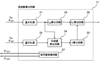
実施の形態1では、事象Aおよび事象Bとなる周波数関係の場合、正しくfRFを特定できない、もしくはfRFを特定できないことが分かった後に事象Aおよび事象Bとなる周波数関係を避けるようにfCLKを変更するため、正しいfRFの検出に時間が掛かった。実施の形態2では、実施の形態1で示した周波数検出回路を2つ用いて、それぞれの周波数検出回路内のS/H回路に入力するクロック信号を互いに異なる周波数とすることによって、どちらかの周波数検出回路で事象Aおよび事象Bを避けて正しいfRFを特定する。
fCLK1は信号源13及び信号源14の出力信号の周波数、θCLK11は信号源13の出力信号の初期位相、θCLK12は信号源14の出力信号の初期位相、fout1はフィルタ15の出力信号の周波数、θout11はフィルタ15の出力信号の初期位相、θout12はフィルタ16の出力信号の初期位相、fCLK2は信号源113及び信号源114の出力信号の周波数、θCLK21は信号源113の出力信号の初期位相、θCLK22は信号源114の出力信号の初期位相、fout2はフィルタ115の出力信号の周波数、θout21はフィルタ115の出力信号の初期位相、θout22はフィルタ116の出力信号の初期位相である。
Claims (9)
- 第1のクロック信号を出力する第1の信号源と、
前記第1のクロック信号と周波数は同じで位相が異なる第2のクロック信号を出力する第2の信号源と、
前記第1のクロック信号を用いて受信信号をアンダーサンプリングする第1のサンプルホールド回路と、
前記第2のクロック信号を用いて前記受信信号をアンダーサンプリングする第2のサンプルホールド回路と、
前記第1のサンプルホールド回路と前記第2のサンプルホールド回路との出力信号の位相差を用いて、前記受信信号の周波数を算出する周波数算出回路と、
を備え、
前記周波数算出回路は、前記第1のサンプルホールド回路の出力信号の周波数を検出するとともに前記位相差を用いて前記受信信号に対するアンダーサンプリングの次数を算出し、算出した前記次数及び検出した前記周波数から前記受信信号の周波数を算出する周波数検出回路。 - 前記周波数算出回路は、前記第1のクロック信号と前記第2のクロック信号との位相差、及び前記第1のサンプルホールド回路と前記第2のサンプルホールド回路と出力信号の位相差から前記受信信号に対するアンダーサンプリングの前記次数を算出することを特徴とする請求項1に記載の周波数検出回路。
- 前記周波数算出回路は、前記第1のクロック信号の位相をθCLK1とし、前記第2のクロック信号の位相をθCLK2とし、前記第1のサンプルホールド回路の出力信号の位相をθout1とし、前記第2のサンプルホールド回路の出力信号の位相をθout2としたとき、以下の式
により求まるnをアンダーサンプリングの前記次数として求めることを特徴とする請求項2に記載の周波数検出回路。
- 前記周波数算出回路は、前記第1のクロック信号の周波数をfCLKとし、前記第1のサンプルホールド回路の出力信号の周波数をfoutとし、これらと請求項3に記載の前記nを用いて、以下の式
を満たすfRFを記受信信号の周波数として算出することを特徴とする請求項3に記載の周波数検出回路。 - 前記周波数算出回路は、前記第1のクロック信号の位相をθCLK1とし、前記第2のクロック信号の位相をθCLK2とし、前記第1のサンプルホールド回路の出力信号の位相をθout1とし、前記第2のサンプルホールド回路の出力信号の位相をθout2としたとき、以下の式
により求まるnをアンダーサンプリングの前記次数として求めることを特徴とする請求項2に記載の周波数検出回路。 - 前記周波数算出回路は、前記第1のクロック信号の周波数をfCLKとし、前記第1のサンプルホールド回路の出力信号の周波数をfoutとし、これらと請求項5に記載の前記nを用いて、以下の式
を満たすfRFを前記受信信号の周波数として算出することを特徴とする請求項5に記載の周波数検出回路。 - 前記周波数算出回路は、前記第1の信号源及び前記第2の信号源にそれぞれ前記第1のクロック信号の位相情報及び前記第2のクロック信号の位相情報を出力することを特徴とする請求項1に記載の周波数検出回路。
- 前記受信信号の周波数を算出する第1の請求項1記載の周波数検出回路と、
前記第1の請求項1記載の周波数検出回路の第1のクロック信号の周波数とは異なる周波数でアンダーサンプリングし、前記受信信号の周波数を算出する第2の請求項1記載の周波数検出回路と、
前記第1の請求項1記載の周波数検出回路が算出した前記受信信号の周波数と前記第2の請求項1記載の周波数検出回路が算出した前記受信信号の周波数とを比較し、前記受信信号の周波数を判定する判定回路と、
を備えた周波数検出回路。 - 前記判定回路は、前記第1の請求項1記載の周波数検出回路が算出したアンダーサンプリングの次数と前記第2の請求項1記載の周波数検出回路が算出したアンダーサンプリングの次数とを比較し、前記受信信号の周波数を判定することを特徴とする請求項8に記載の周波数検出回路。
Applications Claiming Priority (1)
| Application Number | Priority Date | Filing Date | Title |
|---|---|---|---|
| PCT/JP2019/001761 WO2020152764A1 (ja) | 2019-01-22 | 2019-01-22 | 周波数検出回路 |
Publications (2)
| Publication Number | Publication Date |
|---|---|
| JPWO2020152764A1 JPWO2020152764A1 (ja) | 2021-03-11 |
| JP6896189B2 true JP6896189B2 (ja) | 2021-06-30 |
Family
ID=71736248
Family Applications (1)
| Application Number | Title | Priority Date | Filing Date |
|---|---|---|---|
| JP2020563731A Active JP6896189B2 (ja) | 2019-01-22 | 2019-01-22 | 周波数検出回路 |
Country Status (4)
| Country | Link |
|---|---|
| US (1) | US11726118B2 (ja) |
| EP (1) | EP3896465B1 (ja) |
| JP (1) | JP6896189B2 (ja) |
| WO (1) | WO2020152764A1 (ja) |
Families Citing this family (3)
| Publication number | Priority date | Publication date | Assignee | Title |
|---|---|---|---|---|
| JP7055256B2 (ja) * | 2019-11-26 | 2022-04-15 | 三菱電機株式会社 | 周波数検出回路及び受信装置 |
| CN112880808A (zh) * | 2021-02-25 | 2021-06-01 | 广东博智林机器人有限公司 | 自适应的振动频率检测方法、装置、电子设备及存储介质 |
| WO2025262963A1 (ja) * | 2024-06-21 | 2025-12-26 | 三菱電機株式会社 | 受信機 |
Family Cites Families (12)
| Publication number | Priority date | Publication date | Assignee | Title |
|---|---|---|---|---|
| US4348735A (en) * | 1980-06-23 | 1982-09-07 | Bell Telephone Laboratories, Incorporated | Cyclotomic tone detector and locator |
| JP2000284008A (ja) * | 1999-03-30 | 2000-10-13 | Matsushita Electric Ind Co Ltd | 周波数測定方法及び周波数測定装置 |
| US7194365B1 (en) * | 2004-08-31 | 2007-03-20 | Synopsys, Inc. | Method and apparatus for integrated undersampling |
| US7382304B2 (en) * | 2005-10-13 | 2008-06-03 | Guzik Technical Enterprises | Sampling and measurement of periodic signals |
| JP3877749B2 (ja) * | 2005-12-05 | 2007-02-07 | 古野電気株式会社 | 信号処理方法、信号処理装置 |
| EP1847844A1 (en) * | 2006-04-21 | 2007-10-24 | Agilent Technologies, Inc. | Digital data signal analysis by evaluating sampled values in conjuction with signal bit values |
| JP5125520B2 (ja) * | 2008-01-08 | 2013-01-23 | 日本電気株式会社 | 周波数測定装置、周波数測定方法、周波数測定プログラム、及びデータ構造 |
| US8229706B2 (en) * | 2008-06-10 | 2012-07-24 | Advantest Corporation | Sampling apparatus, sampling method and recording medium |
| CN105510706B (zh) * | 2015-12-30 | 2018-12-14 | 中国航天时代电子公司 | 一种高精度欠采样测频方法 |
| JP6684399B2 (ja) * | 2016-05-31 | 2020-04-22 | 国立研究開発法人情報通信研究機構 | コヒーレントサンプリング |
| JP6217887B1 (ja) * | 2017-02-27 | 2017-10-25 | 三菱電機株式会社 | 周波数算出装置及びレーダ装置 |
| JP2018174415A (ja) * | 2017-03-31 | 2018-11-08 | 国立大学法人東北大学 | マルチバンド受信装置、及びマルチバンド高周波信号の受信方法 |
-
2019
- 2019-01-22 EP EP19911540.3A patent/EP3896465B1/en active Active
- 2019-01-22 JP JP2020563731A patent/JP6896189B2/ja active Active
- 2019-01-22 WO PCT/JP2019/001761 patent/WO2020152764A1/ja not_active Ceased
-
2021
- 2021-06-18 US US17/351,597 patent/US11726118B2/en active Active
Also Published As
| Publication number | Publication date |
|---|---|
| US11726118B2 (en) | 2023-08-15 |
| JPWO2020152764A1 (ja) | 2021-03-11 |
| EP3896465B1 (en) | 2022-07-27 |
| WO2020152764A1 (ja) | 2020-07-30 |
| US20210311098A1 (en) | 2021-10-07 |
| EP3896465A4 (en) | 2022-01-12 |
| EP3896465A1 (en) | 2021-10-20 |
Similar Documents
| Publication | Publication Date | Title |
|---|---|---|
| US12609709B2 (en) | High linearity phase interpolator | |
| US8571161B2 (en) | Electronic device for generating a fractional frequency | |
| CN107924158B (zh) | 校准高分辨率数字到时间转换器中的动态误差 | |
| JP6896189B2 (ja) | 周波数検出回路 | |
| US6396313B1 (en) | Noise-shaped digital frequency synthesis | |
| US10218373B1 (en) | Analog-to-digital converter calibration system | |
| US20220029721A1 (en) | Systems, methods, and apparatus for time division multiplexed spur reduction | |
| EP3333650A1 (en) | System and method for calibrating a time to digital converter device | |
| US12057855B2 (en) | Circuit for converting a signal between digital and analog | |
| US20220221498A1 (en) | Frequency detection circuit and reception device | |
| US9685961B2 (en) | High resolution timing device and radar detection system having the same | |
| JP7486700B1 (ja) | 到来電波測定装置 | |
| US8724762B2 (en) | Clock regeneration method, reference-less receiver, and crystal-less system | |
| US7555091B1 (en) | System and method for providing a clock and data recovery circuit with a self test capability | |
| US11632229B2 (en) | Signal transceiver circuit, method of operating signal transmitting circuit, and method of setting delay circuit | |
| US20040108948A1 (en) | Analogue to digital converter | |
| EP3790193B1 (en) | Apparatuses and methods for generating time resolution for electronic devices | |
| Nawaz et al. | Comparative survey on time interleaved analog to digital converter mismatches compensation techniques | |
| EP4568114A1 (en) | Analog-to-digital conversion circuit, receiver including the same, and timing calibration circuit | |
| US20230336194A1 (en) | Multi-frequency sampling system | |
| WO2024111033A1 (ja) | 周波数検出回路及び周波数検出システム | |
| CN114745000A (zh) | 一种用于降低锁相环路整数边界杂散的电路及其方法 | |
| Niaboli-Guilani et al. | A low-power digital calibration of sampling time mismatches in time-interleaved A/D converters | |
| Estrada | Proper frequency planning in a Synthetic Instrument RF system |
Legal Events
| Date | Code | Title | Description |
|---|---|---|---|
| A621 | Written request for application examination |
Free format text: JAPANESE INTERMEDIATE CODE: A621 Effective date: 20201110 |
|
| A871 | Explanation of circumstances concerning accelerated examination |
Free format text: JAPANESE INTERMEDIATE CODE: A871 Effective date: 20201110 |
|
| A975 | Report on accelerated examination |
Free format text: JAPANESE INTERMEDIATE CODE: A971005 Effective date: 20201126 |
|
| A131 | Notification of reasons for refusal |
Free format text: JAPANESE INTERMEDIATE CODE: A131 Effective date: 20201215 |
|
| A521 | Request for written amendment filed |
Free format text: JAPANESE INTERMEDIATE CODE: A523 Effective date: 20210203 |
|
| A131 | Notification of reasons for refusal |
Free format text: JAPANESE INTERMEDIATE CODE: A131 Effective date: 20210323 |
|
| A521 | Request for written amendment filed |
Free format text: JAPANESE INTERMEDIATE CODE: A523 Effective date: 20210414 |
|
| TRDD | Decision of grant or rejection written | ||
| A01 | Written decision to grant a patent or to grant a registration (utility model) |
Free format text: JAPANESE INTERMEDIATE CODE: A01 Effective date: 20210511 |
|
| A61 | First payment of annual fees (during grant procedure) |
Free format text: JAPANESE INTERMEDIATE CODE: A61 Effective date: 20210608 |
|
| R150 | Certificate of patent or registration of utility model |
Ref document number: 6896189 Country of ref document: JP Free format text: JAPANESE INTERMEDIATE CODE: R150 |
|
| R250 | Receipt of annual fees |
Free format text: JAPANESE INTERMEDIATE CODE: R250 |
|
| R250 | Receipt of annual fees |
Free format text: JAPANESE INTERMEDIATE CODE: R250 |