JP6900909B2 - 多相コンバータシステム - Google Patents
多相コンバータシステム Download PDFInfo
- Publication number
- JP6900909B2 JP6900909B2 JP2018002194A JP2018002194A JP6900909B2 JP 6900909 B2 JP6900909 B2 JP 6900909B2 JP 2018002194 A JP2018002194 A JP 2018002194A JP 2018002194 A JP2018002194 A JP 2018002194A JP 6900909 B2 JP6900909 B2 JP 6900909B2
- Authority
- JP
- Japan
- Prior art keywords
- converter
- temperature
- refrigerant
- controller
- phase converter
- Prior art date
- Legal status (The legal status is an assumption and is not a legal conclusion. Google has not performed a legal analysis and makes no representation as to the accuracy of the status listed.)
- Active
Links
Images


Classifications
-
- H—ELECTRICITY
- H02—GENERATION; CONVERSION OR DISTRIBUTION OF ELECTRIC POWER
- H02M—APPARATUS FOR CONVERSION BETWEEN AC AND AC, BETWEEN AC AND DC, OR BETWEEN DC AND DC, AND FOR USE WITH MAINS OR SIMILAR POWER SUPPLY SYSTEMS; CONVERSION OF DC OR AC INPUT POWER INTO SURGE OUTPUT POWER; CONTROL OR REGULATION THEREOF
- H02M3/00—Conversion of DC power input into DC power output
- H02M3/02—Conversion of DC power input into DC power output without intermediate conversion into AC
- H02M3/04—Conversion of DC power input into DC power output without intermediate conversion into AC by static converters
- H02M3/10—Conversion of DC power input into DC power output without intermediate conversion into AC by static converters using discharge tubes with control electrode or semiconductor devices with control electrode
- H02M3/145—Conversion of DC power input into DC power output without intermediate conversion into AC by static converters using discharge tubes with control electrode or semiconductor devices with control electrode using devices of a triode or transistor type requiring continuous application of a control signal
- H02M3/155—Conversion of DC power input into DC power output without intermediate conversion into AC by static converters using discharge tubes with control electrode or semiconductor devices with control electrode using devices of a triode or transistor type requiring continuous application of a control signal using semiconductor devices only
- H02M3/156—Conversion of DC power input into DC power output without intermediate conversion into AC by static converters using discharge tubes with control electrode or semiconductor devices with control electrode using devices of a triode or transistor type requiring continuous application of a control signal using semiconductor devices only with automatic control of output voltage or current, e.g. switching regulators
- H02M3/158—Conversion of DC power input into DC power output without intermediate conversion into AC by static converters using discharge tubes with control electrode or semiconductor devices with control electrode using devices of a triode or transistor type requiring continuous application of a control signal using semiconductor devices only with automatic control of output voltage or current, e.g. switching regulators including plural semiconductor devices as final control devices for a single load
- H02M3/1584—Conversion of DC power input into DC power output without intermediate conversion into AC by static converters using discharge tubes with control electrode or semiconductor devices with control electrode using devices of a triode or transistor type requiring continuous application of a control signal using semiconductor devices only with automatic control of output voltage or current, e.g. switching regulators including plural semiconductor devices as final control devices for a single load with a plurality of power processing stages connected in parallel
-
- H—ELECTRICITY
- H02—GENERATION; CONVERSION OR DISTRIBUTION OF ELECTRIC POWER
- H02M—APPARATUS FOR CONVERSION BETWEEN AC AND AC, BETWEEN AC AND DC, OR BETWEEN DC AND DC, AND FOR USE WITH MAINS OR SIMILAR POWER SUPPLY SYSTEMS; CONVERSION OF DC OR AC INPUT POWER INTO SURGE OUTPUT POWER; CONTROL OR REGULATION THEREOF
- H02M3/00—Conversion of DC power input into DC power output
- H02M3/02—Conversion of DC power input into DC power output without intermediate conversion into AC
- H02M3/04—Conversion of DC power input into DC power output without intermediate conversion into AC by static converters
- H02M3/10—Conversion of DC power input into DC power output without intermediate conversion into AC by static converters using discharge tubes with control electrode or semiconductor devices with control electrode
- H02M3/145—Conversion of DC power input into DC power output without intermediate conversion into AC by static converters using discharge tubes with control electrode or semiconductor devices with control electrode using devices of a triode or transistor type requiring continuous application of a control signal
- H02M3/155—Conversion of DC power input into DC power output without intermediate conversion into AC by static converters using discharge tubes with control electrode or semiconductor devices with control electrode using devices of a triode or transistor type requiring continuous application of a control signal using semiconductor devices only
- H02M3/156—Conversion of DC power input into DC power output without intermediate conversion into AC by static converters using discharge tubes with control electrode or semiconductor devices with control electrode using devices of a triode or transistor type requiring continuous application of a control signal using semiconductor devices only with automatic control of output voltage or current, e.g. switching regulators
- H02M3/158—Conversion of DC power input into DC power output without intermediate conversion into AC by static converters using discharge tubes with control electrode or semiconductor devices with control electrode using devices of a triode or transistor type requiring continuous application of a control signal using semiconductor devices only with automatic control of output voltage or current, e.g. switching regulators including plural semiconductor devices as final control devices for a single load
-
- H—ELECTRICITY
- H02—GENERATION; CONVERSION OR DISTRIBUTION OF ELECTRIC POWER
- H02P—CONTROL OR REGULATION OF ELECTRIC MOTORS, ELECTRIC GENERATORS OR DYNAMO-ELECTRIC CONVERTERS; CONTROLLING TRANSFORMERS, REACTORS OR CHOKE COILS
- H02P29/00—Arrangements for regulating or controlling electric motors, appropriate for both AC and DC motors
- H02P29/60—Controlling or determining the temperature of the motor or of the drive
- H02P29/68—Controlling or determining the temperature of the motor or of the drive based on the temperature of a drive component or a semiconductor component
-
- B—PERFORMING OPERATIONS; TRANSPORTING
- B60—VEHICLES IN GENERAL
- B60L—PROPULSION OF ELECTRICALLY-PROPELLED VEHICLES; SUPPLYING ELECTRIC POWER FOR AUXILIARY EQUIPMENT OF ELECTRICALLY-PROPELLED VEHICLES; ELECTRODYNAMIC BRAKE SYSTEMS FOR VEHICLES IN GENERAL; MAGNETIC SUSPENSION OR LEVITATION FOR VEHICLES; MONITORING OPERATING VARIABLES OF ELECTRICALLY-PROPELLED VEHICLES; ELECTRIC SAFETY DEVICES FOR ELECTRICALLY-PROPELLED VEHICLES
- B60L2210/00—Converter types
- B60L2210/10—DC to DC converters
- B60L2210/14—Boost converters
-
- H—ELECTRICITY
- H02—GENERATION; CONVERSION OR DISTRIBUTION OF ELECTRIC POWER
- H02M—APPARATUS FOR CONVERSION BETWEEN AC AND AC, BETWEEN AC AND DC, OR BETWEEN DC AND DC, AND FOR USE WITH MAINS OR SIMILAR POWER SUPPLY SYSTEMS; CONVERSION OF DC OR AC INPUT POWER INTO SURGE OUTPUT POWER; CONTROL OR REGULATION THEREOF
- H02M1/00—Details of apparatus for conversion
- H02M1/0003—Details of control, feedback or regulation circuits
- H02M1/0032—Control circuits allowing low power mode operation, e.g. in standby mode
-
- H—ELECTRICITY
- H02—GENERATION; CONVERSION OR DISTRIBUTION OF ELECTRIC POWER
- H02M—APPARATUS FOR CONVERSION BETWEEN AC AND AC, BETWEEN AC AND DC, OR BETWEEN DC AND DC, AND FOR USE WITH MAINS OR SIMILAR POWER SUPPLY SYSTEMS; CONVERSION OF DC OR AC INPUT POWER INTO SURGE OUTPUT POWER; CONTROL OR REGULATION THEREOF
- H02M1/00—Details of apparatus for conversion
- H02M1/0048—Circuits or arrangements for reducing losses
- H02M1/0054—Transistor switching losses
-
- H—ELECTRICITY
- H02—GENERATION; CONVERSION OR DISTRIBUTION OF ELECTRIC POWER
- H02M—APPARATUS FOR CONVERSION BETWEEN AC AND AC, BETWEEN AC AND DC, OR BETWEEN DC AND DC, AND FOR USE WITH MAINS OR SIMILAR POWER SUPPLY SYSTEMS; CONVERSION OF DC OR AC INPUT POWER INTO SURGE OUTPUT POWER; CONTROL OR REGULATION THEREOF
- H02M1/00—Details of apparatus for conversion
- H02M1/0067—Converter structures employing plural converter units, other than for parallel operation of the units on a single load
- H02M1/007—Plural converter units in cascade
-
- H—ELECTRICITY
- H02—GENERATION; CONVERSION OR DISTRIBUTION OF ELECTRIC POWER
- H02M—APPARATUS FOR CONVERSION BETWEEN AC AND AC, BETWEEN AC AND DC, OR BETWEEN DC AND DC, AND FOR USE WITH MAINS OR SIMILAR POWER SUPPLY SYSTEMS; CONVERSION OF DC OR AC INPUT POWER INTO SURGE OUTPUT POWER; CONTROL OR REGULATION THEREOF
- H02M3/00—Conversion of DC power input into DC power output
- H02M3/02—Conversion of DC power input into DC power output without intermediate conversion into AC
- H02M3/04—Conversion of DC power input into DC power output without intermediate conversion into AC by static converters
- H02M3/10—Conversion of DC power input into DC power output without intermediate conversion into AC by static converters using discharge tubes with control electrode or semiconductor devices with control electrode
- H02M3/145—Conversion of DC power input into DC power output without intermediate conversion into AC by static converters using discharge tubes with control electrode or semiconductor devices with control electrode using devices of a triode or transistor type requiring continuous application of a control signal
- H02M3/155—Conversion of DC power input into DC power output without intermediate conversion into AC by static converters using discharge tubes with control electrode or semiconductor devices with control electrode using devices of a triode or transistor type requiring continuous application of a control signal using semiconductor devices only
- H02M3/156—Conversion of DC power input into DC power output without intermediate conversion into AC by static converters using discharge tubes with control electrode or semiconductor devices with control electrode using devices of a triode or transistor type requiring continuous application of a control signal using semiconductor devices only with automatic control of output voltage or current, e.g. switching regulators
- H02M3/158—Conversion of DC power input into DC power output without intermediate conversion into AC by static converters using discharge tubes with control electrode or semiconductor devices with control electrode using devices of a triode or transistor type requiring continuous application of a control signal using semiconductor devices only with automatic control of output voltage or current, e.g. switching regulators including plural semiconductor devices as final control devices for a single load
- H02M3/1584—Conversion of DC power input into DC power output without intermediate conversion into AC by static converters using discharge tubes with control electrode or semiconductor devices with control electrode using devices of a triode or transistor type requiring continuous application of a control signal using semiconductor devices only with automatic control of output voltage or current, e.g. switching regulators including plural semiconductor devices as final control devices for a single load with a plurality of power processing stages connected in parallel
- H02M3/1586—Conversion of DC power input into DC power output without intermediate conversion into AC by static converters using discharge tubes with control electrode or semiconductor devices with control electrode using devices of a triode or transistor type requiring continuous application of a control signal using semiconductor devices only with automatic control of output voltage or current, e.g. switching regulators including plural semiconductor devices as final control devices for a single load with a plurality of power processing stages connected in parallel switched with a phase shift, i.e. interleaved
-
- H—ELECTRICITY
- H02—GENERATION; CONVERSION OR DISTRIBUTION OF ELECTRIC POWER
- H02P—CONTROL OR REGULATION OF ELECTRIC MOTORS, ELECTRIC GENERATORS OR DYNAMO-ELECTRIC CONVERTERS; CONTROLLING TRANSFORMERS, REACTORS OR CHOKE COILS
- H02P2201/00—Indexing scheme relating to controlling arrangements characterised by the converter used
- H02P2201/09—Boost converter, i.e. DC-DC step up converter increasing the voltage between the supply and the inverter driving the motor
-
- H—ELECTRICITY
- H02—GENERATION; CONVERSION OR DISTRIBUTION OF ELECTRIC POWER
- H02P—CONTROL OR REGULATION OF ELECTRIC MOTORS, ELECTRIC GENERATORS OR DYNAMO-ELECTRIC CONVERTERS; CONTROLLING TRANSFORMERS, REACTORS OR CHOKE COILS
- H02P27/00—Arrangements or methods for the control of AC motors characterised by the kind of supply voltage
- H02P27/04—Arrangements or methods for the control of AC motors characterised by the kind of supply voltage using variable-frequency supply voltage, e.g. inverter or converter supply voltage
- H02P27/06—Arrangements or methods for the control of AC motors characterised by the kind of supply voltage using variable-frequency supply voltage, e.g. inverter or converter supply voltage using DC to AC converters or inverters
-
- Y—GENERAL TAGGING OF NEW TECHNOLOGICAL DEVELOPMENTS; GENERAL TAGGING OF CROSS-SECTIONAL TECHNOLOGIES SPANNING OVER SEVERAL SECTIONS OF THE IPC; TECHNICAL SUBJECTS COVERED BY FORMER USPC CROSS-REFERENCE ART COLLECTIONS [XRACs] AND DIGESTS
- Y02—TECHNOLOGIES OR APPLICATIONS FOR MITIGATION OR ADAPTATION AGAINST CLIMATE CHANGE
- Y02B—CLIMATE CHANGE MITIGATION TECHNOLOGIES RELATED TO BUILDINGS, e.g. HOUSING, HOUSE APPLIANCES OR RELATED END-USER APPLICATIONS
- Y02B70/00—Technologies for an efficient end-user side electric power management and consumption
- Y02B70/10—Technologies improving the efficiency by using switched-mode power supplies [SMPS], i.e. efficient power electronics conversion e.g. power factor correction or reduction of losses in power supplies or efficient standby modes
-
- Y—GENERAL TAGGING OF NEW TECHNOLOGICAL DEVELOPMENTS; GENERAL TAGGING OF CROSS-SECTIONAL TECHNOLOGIES SPANNING OVER SEVERAL SECTIONS OF THE IPC; TECHNICAL SUBJECTS COVERED BY FORMER USPC CROSS-REFERENCE ART COLLECTIONS [XRACs] AND DIGESTS
- Y02—TECHNOLOGIES OR APPLICATIONS FOR MITIGATION OR ADAPTATION AGAINST CLIMATE CHANGE
- Y02T—CLIMATE CHANGE MITIGATION TECHNOLOGIES RELATED TO TRANSPORTATION
- Y02T10/00—Road transport of goods or passengers
- Y02T10/60—Other road transportation technologies with climate change mitigation effect
- Y02T10/70—Energy storage systems for electromobility, e.g. batteries
-
- Y—GENERAL TAGGING OF NEW TECHNOLOGICAL DEVELOPMENTS; GENERAL TAGGING OF CROSS-SECTIONAL TECHNOLOGIES SPANNING OVER SEVERAL SECTIONS OF THE IPC; TECHNICAL SUBJECTS COVERED BY FORMER USPC CROSS-REFERENCE ART COLLECTIONS [XRACs] AND DIGESTS
- Y02—TECHNOLOGIES OR APPLICATIONS FOR MITIGATION OR ADAPTATION AGAINST CLIMATE CHANGE
- Y02T—CLIMATE CHANGE MITIGATION TECHNOLOGIES RELATED TO TRANSPORTATION
- Y02T10/00—Road transport of goods or passengers
- Y02T10/60—Other road transportation technologies with climate change mitigation effect
- Y02T10/7072—Electromobility specific charging systems or methods for batteries, ultracapacitors, supercapacitors or double-layer capacitors
-
- Y—GENERAL TAGGING OF NEW TECHNOLOGICAL DEVELOPMENTS; GENERAL TAGGING OF CROSS-SECTIONAL TECHNOLOGIES SPANNING OVER SEVERAL SECTIONS OF THE IPC; TECHNICAL SUBJECTS COVERED BY FORMER USPC CROSS-REFERENCE ART COLLECTIONS [XRACs] AND DIGESTS
- Y02—TECHNOLOGIES OR APPLICATIONS FOR MITIGATION OR ADAPTATION AGAINST CLIMATE CHANGE
- Y02T—CLIMATE CHANGE MITIGATION TECHNOLOGIES RELATED TO TRANSPORTATION
- Y02T90/00—Enabling technologies or technologies with a potential or indirect contribution to GHG emissions mitigation
- Y02T90/10—Technologies relating to charging of electric vehicles
- Y02T90/14—Plug-in electric vehicles
Landscapes
- Engineering & Computer Science (AREA)
- Power Engineering (AREA)
- Dc-Dc Converters (AREA)
Description
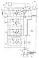
3a−3d:スイッチング素子
4a−4d、6a−6d:ダイオード
5a−5d:リアクトル
10:多相コンバータ
12a−12d:コンバータ
17:コントローラ
21:燃料電池
22、24:コンデンサ
25:電圧センサ
26:リレー
27:インバータ
28:モータ
30:冷却器
31:循環路
32:ポンプ
33:リザーブタンク
34:温度センサ
35:ラジエータ
100:電気自動車
Claims (3)
- 複数のコンバータが並列に接続されている多相コンバータと、
冷媒を流して前記コンバータを冷却する冷却器と、
前記冷媒の温度を計測する温度センサと、
コントローラと、
を備えており、
前記コントローラは、
前記多相コンバータの目標出力が所定の出力閾値よりも低く、前記冷媒の温度が所定の温度範囲内である場合はn相の前記コンバータを駆動し、
前記目標出力が前記出力閾値よりも低く、前記冷媒の温度が前記温度範囲よりも低い場合はnよりも多いm相の前記コンバータを駆動する、
多相コンバータシステム。 - 前記コントローラは、前記目標出力が前記出力閾値よりも低く、前記冷媒の温度が前記温度範囲よりも低い場合は全相の前記コンバータを駆動する、請求項1に記載の多相コンバータシステム。
- 前記コンバータは昇圧コンバータであり、
前記コントローラは、
前記冷媒の温度が前記温度範囲内である場合は前記多相コンバータの出力電圧の上限を第1電圧上限値に設定し、
前記冷媒の温度が前記温度範囲よりも低い場合は前記多相コンバータの出力電圧の上限を前記第1電圧上限値よりも低い第2電圧上限値に設定する、
請求項1又は2に記載の多相コンバータシステム。
Priority Applications (3)
| Application Number | Priority Date | Filing Date | Title |
|---|---|---|---|
| JP2018002194A JP6900909B2 (ja) | 2018-01-10 | 2018-01-10 | 多相コンバータシステム |
| US16/232,866 US10630182B2 (en) | 2018-01-10 | 2018-12-26 | Multiphase converter system for variable driving of phases based on cooling medium temperature |
| CN201910015296.7A CN110022063B (zh) | 2018-01-10 | 2019-01-08 | 多相转换器系统 |
Applications Claiming Priority (1)
| Application Number | Priority Date | Filing Date | Title |
|---|---|---|---|
| JP2018002194A JP6900909B2 (ja) | 2018-01-10 | 2018-01-10 | 多相コンバータシステム |
Publications (2)
| Publication Number | Publication Date |
|---|---|
| JP2019122198A JP2019122198A (ja) | 2019-07-22 |
| JP6900909B2 true JP6900909B2 (ja) | 2021-07-07 |
Family
ID=67159864
Family Applications (1)
| Application Number | Title | Priority Date | Filing Date |
|---|---|---|---|
| JP2018002194A Active JP6900909B2 (ja) | 2018-01-10 | 2018-01-10 | 多相コンバータシステム |
Country Status (3)
| Country | Link |
|---|---|
| US (1) | US10630182B2 (ja) |
| JP (1) | JP6900909B2 (ja) |
| CN (1) | CN110022063B (ja) |
Families Citing this family (7)
| Publication number | Priority date | Publication date | Assignee | Title |
|---|---|---|---|---|
| DE102018204845A1 (de) * | 2018-03-29 | 2019-10-02 | Audi Ag | Multiphasenwandler |
| JP7044055B2 (ja) * | 2018-12-26 | 2022-03-30 | トヨタ自動車株式会社 | 車両の暖機制御装置 |
| DE102019213073A1 (de) * | 2019-08-30 | 2021-03-04 | Robert Bosch Gmbh | Verfahren zum Betrieb parallel geschalteter Spannungswandler |
| US11038426B2 (en) * | 2019-09-19 | 2021-06-15 | National Instruments Corporation | Multi-phase noise cancelled adjustable switched mode programmable load |
| US11569747B2 (en) * | 2021-03-05 | 2023-01-31 | Apple Inc. | Adaptive phase add/shed for a power converter |
| JP7548202B2 (ja) * | 2021-12-15 | 2024-09-10 | トヨタ自動車株式会社 | 電力制御装置とそれを用いた電力供給システム |
| DE102022209345A1 (de) * | 2022-09-08 | 2024-03-14 | Robert Bosch Gesellschaft mit beschränkter Haftung | Brennstoffzellensystem sowie Verfahren zum Kontrollieren eines Heizstromes für ein Temperieren eines Brennstoffzellenstapels eines Brennstoffzellensystems |
Family Cites Families (13)
| Publication number | Priority date | Publication date | Assignee | Title |
|---|---|---|---|---|
| JP4274271B2 (ja) * | 2007-07-26 | 2009-06-03 | トヨタ自動車株式会社 | 電圧変換装置 |
| JP5092810B2 (ja) * | 2008-03-07 | 2012-12-05 | パナソニック株式会社 | 蓄電装置 |
| WO2010140228A1 (ja) * | 2009-06-03 | 2010-12-09 | トヨタ自動車株式会社 | コンバータ制御装置 |
| JP2011019338A (ja) * | 2009-07-08 | 2011-01-27 | Toyota Motor Corp | コンバータ制御装置 |
| DE112011105418T5 (de) * | 2011-07-05 | 2014-04-03 | Toyota Jidosha Kabushiki Kaisha | Brennstoffzellensystem |
| WO2013011560A1 (ja) * | 2011-07-19 | 2013-01-24 | トヨタ自動車株式会社 | 電源システム |
| US8878501B2 (en) * | 2011-09-01 | 2014-11-04 | Micrel, Inc. | Multi-phase power block for a switching regulator for use with a single-phase PWM controller |
| JP5880519B2 (ja) * | 2013-10-21 | 2016-03-09 | トヨタ自動車株式会社 | 車載電子装置 |
| JP6172114B2 (ja) * | 2014-10-28 | 2017-08-02 | トヨタ自動車株式会社 | ハイブリッド自動車 |
| JP6191586B2 (ja) * | 2014-12-02 | 2017-09-06 | トヨタ自動車株式会社 | モータコントローラ、電動車両、及び、スイッチング素子の熱ストレス推定方法 |
| JP6292154B2 (ja) * | 2015-03-19 | 2018-03-14 | トヨタ自動車株式会社 | 電源システム |
| JP6575815B2 (ja) * | 2015-12-01 | 2019-09-18 | 株式会社デンソー | 電源システム |
| JP2017103990A (ja) * | 2015-12-04 | 2017-06-08 | トヨタ自動車株式会社 | 走行用のモータを備える自動車 |
-
2018
- 2018-01-10 JP JP2018002194A patent/JP6900909B2/ja active Active
- 2018-12-26 US US16/232,866 patent/US10630182B2/en active Active
-
2019
- 2019-01-08 CN CN201910015296.7A patent/CN110022063B/zh active Active
Also Published As
| Publication number | Publication date |
|---|---|
| US10630182B2 (en) | 2020-04-21 |
| CN110022063A (zh) | 2019-07-16 |
| CN110022063B (zh) | 2021-04-13 |
| JP2019122198A (ja) | 2019-07-22 |
| US20190214913A1 (en) | 2019-07-11 |
Similar Documents
| Publication | Publication Date | Title |
|---|---|---|
| JP6900909B2 (ja) | 多相コンバータシステム | |
| US12132432B2 (en) | Energy conversion device and vehicle | |
| US10411588B2 (en) | Power converter with trench and planar transistors to improve efficiency | |
| JP5634327B2 (ja) | Dc/dcコンバータ装置 | |
| US8765312B2 (en) | Converter controlling apparatus | |
| US20120069604A1 (en) | Compact power converter with high efficiency in operation | |
| CN105075102A (zh) | 电力转换装置、具备其的电动机驱动装置、具备其的鼓风机、压缩机、以及具备这些的空调机、冰箱和制冷机 | |
| JP6922635B2 (ja) | 電力変換装置 | |
| JP6218906B1 (ja) | 電力変換装置 | |
| KR20200020363A (ko) | 차량용 인버터 시스템 | |
| JP6135563B2 (ja) | 電圧コンバータ | |
| EP2509207A2 (en) | Power conversion system | |
| JP2014023263A (ja) | 電気自動車 | |
| CN106712639B (zh) | 电动驱动装置以及电动设备 | |
| JP2017200262A (ja) | 電力変換装置 | |
| JP2019146374A (ja) | 電力変換装置 | |
| JP7028843B2 (ja) | 電力変換装置 | |
| JP5333007B2 (ja) | 燃料電池システム | |
| US20240136967A1 (en) | Power conversion device | |
| JP2021090317A (ja) | 電力変換システム | |
| JP5721669B2 (ja) | 電力変換装置および冷凍空調システム | |
| JP2024157656A (ja) | 電源システム | |
| JP2025126117A (ja) | 移動体の制御装置、記憶媒体、および、プログラム | |
| JP2021112091A (ja) | 電力変換システム | |
| CN117507844A (zh) | 一种用于电动汽车的混合动力总成以及电动汽车 |
Legal Events
| Date | Code | Title | Description |
|---|---|---|---|
| A621 | Written request for application examination |
Free format text: JAPANESE INTERMEDIATE CODE: A621 Effective date: 20200728 |
|
| TRDD | Decision of grant or rejection written | ||
| A01 | Written decision to grant a patent or to grant a registration (utility model) |
Free format text: JAPANESE INTERMEDIATE CODE: A01 Effective date: 20210518 |
|
| A977 | Report on retrieval |
Free format text: JAPANESE INTERMEDIATE CODE: A971007 Effective date: 20210519 |
|
| A61 | First payment of annual fees (during grant procedure) |
Free format text: JAPANESE INTERMEDIATE CODE: A61 Effective date: 20210531 |
|
| R151 | Written notification of patent or utility model registration |
Ref document number: 6900909 Country of ref document: JP Free format text: JAPANESE INTERMEDIATE CODE: R151 |