JP6907304B2 - Vehicle control device and vehicle control method - Google Patents
Vehicle control device and vehicle control method Download PDFInfo
- Publication number
- JP6907304B2 JP6907304B2 JP2019508035A JP2019508035A JP6907304B2 JP 6907304 B2 JP6907304 B2 JP 6907304B2 JP 2019508035 A JP2019508035 A JP 2019508035A JP 2019508035 A JP2019508035 A JP 2019508035A JP 6907304 B2 JP6907304 B2 JP 6907304B2
- Authority
- JP
- Japan
- Prior art keywords
- lane
- vehicle
- intersection
- traveling
- control device
- Prior art date
- Legal status (The legal status is an assumption and is not a legal conclusion. Google has not performed a legal analysis and makes no representation as to the accuracy of the status listed.)
- Active
Links
Images



Classifications
-
- G—PHYSICS
- G08—SIGNALLING
- G08G—TRAFFIC CONTROL SYSTEMS
- G08G1/00—Traffic control systems for road vehicles
- G08G1/16—Anti-collision systems
- G08G1/166—Anti-collision systems for active traffic, e.g. moving vehicles, pedestrians, bikes
-
- G—PHYSICS
- G08—SIGNALLING
- G08G—TRAFFIC CONTROL SYSTEMS
- G08G1/00—Traffic control systems for road vehicles
- G08G1/16—Anti-collision systems
- G08G1/167—Driving aids for lane monitoring, lane changing, e.g. blind spot detection
-
- G—PHYSICS
- G08—SIGNALLING
- G08G—TRAFFIC CONTROL SYSTEMS
- G08G1/00—Traffic control systems for road vehicles
- G08G1/01—Detecting movement of traffic to be counted or controlled
- G08G1/0104—Measuring and analyzing of parameters relative to traffic conditions
- G08G1/0125—Traffic data processing
Landscapes
- Physics & Mathematics (AREA)
- General Physics & Mathematics (AREA)
- Chemical & Material Sciences (AREA)
- Analytical Chemistry (AREA)
- Traffic Control Systems (AREA)
- Control Of Driving Devices And Active Controlling Of Vehicle (AREA)
Description
本発明は、車両制御装置及び車両制御方法に関する。 The present invention relates to a vehicle control device and a vehicle control method.
従来から、自車両の外界状態を示す情報(以下、外界情報)を取得し、その外界情報に基づいて運転支援又は自動運転を行うための制御装置が種々開発されている。 Conventionally, various control devices have been developed for acquiring information indicating the external world state of the own vehicle (hereinafter referred to as external world information) and performing driving support or automatic driving based on the external world information.
特開2003−121180号公報では、地図情報に基づいて仮想道路を作成し、いわゆるマップマッチングを用いて地図上の自車位置を計測する手法が提案されている。これにより、交差点又は分岐点を通過する場合の自車位置を正確に認識できる旨が記載されている。 Japanese Unexamined Patent Publication No. 2003-121180 proposes a method of creating a virtual road based on map information and measuring the position of the own vehicle on a map by using so-called map matching. It is described that this makes it possible to accurately recognize the position of the own vehicle when passing through an intersection or a branch point.
しかしながら、特開2003−121180号公報で提案される手法では、自車位置の認識精度は、地図情報の信頼性に大きく依存してしまう。例えば、交差点の手前側と奥側でレーンが左右方向にずれた状態を認識した場合、実際の走行シーンを正確に把握するのが難しい可能性がある。特に、自動による走行制御を行う場合、この交差点をどのように通過したらよいか対処に迷うことが十分に想定される。 However, in the method proposed in Japanese Patent Application Laid-Open No. 2003-121180, the recognition accuracy of the position of the own vehicle largely depends on the reliability of the map information. For example, when recognizing a state in which the lanes are displaced in the left-right direction on the front side and the back side of the intersection, it may be difficult to accurately grasp the actual driving scene. In particular, when automatic driving control is performed, it is fully assumed that it is difficult to deal with how to pass through this intersection.
本発明は上記した問題を解決するためになされたものであり、交差点の前後方向における走行レーンの接続性に留意しつつ、交差点の直進通過に適切に対処可能な車両制御装置及び車両制御方法を提供することを目的とする。 The present invention has been made to solve the above-mentioned problems, and a vehicle control device and a vehicle control method capable of appropriately coping with a straight-ahead passage of an intersection while paying attention to the connectivity of traveling lanes in the front-rear direction of the intersection. The purpose is to provide.
第1の本発明に係る車両制御装置は、自車両の走行制御を少なくとも部分的に自動で行う装置であって、前記自車両が直進しながら通過しようとする交差点を認識する認識処理部と、前記自車両の走行レーンが、前記認識処理部により認識された前記交差点の手前側と奥側で左右方向にずれるオフセットレーンであるか否かを判定するレーン判定部と、前記レーン判定部による判定結果に応じて異なる走行制御を行う走行制御部と、を備える。 The first vehicle control device according to the present invention is a device that automatically controls the running of the own vehicle at least partially, and includes a recognition processing unit that recognizes an intersection that the own vehicle is about to pass while traveling straight. A lane determination unit that determines whether or not the traveling lane of the own vehicle is an offset lane that is recognized by the recognition processing unit and is displaced in the left-right direction between the front side and the back side of the intersection, and a determination by the lane determination unit. It is provided with a traveling control unit that performs different traveling control according to the result.
このように、オフセットレーンに関する判定結果に応じて異なる走行制御を行うことで、交差点の前後方向における走行レーンの接続性に留意しつつ、交差点の直進通過に適切に対処することができる。 In this way, by performing different travel control according to the determination result regarding the offset lane, it is possible to appropriately deal with the straight passage of the intersection while paying attention to the connectivity of the travel lane in the front-rear direction of the intersection.
また、前記認識処理部は、前記走行レーンの区画線を標示するレーンマークをさらに認識し、前記レーン判定部は、前記レーンマークにより特定される前記交差点の手前側区画線を外挿することで前記交差点内の仮想区画線を設定し、前記走行レーンが前記オフセットレーンであるか否かを前記仮想区画線に基づいて判定してもよい。 Further, the recognition processing unit further recognizes the lane mark indicating the division line of the traveling lane, and the lane determination unit extrapolates the front side division line of the intersection specified by the lane mark. A virtual lane marking in the intersection may be set, and whether or not the traveling lane is the offset lane may be determined based on the virtual lane marking.
また、前記レーン判定部は、前記走行レーンが前記オフセットレーンであると判定した場合、オフセット方向に最も近い奥側区画線と接続し直すことで前記仮想区画線を設定してもよい。 Further, when the lane determination unit determines that the traveling lane is the offset lane, the virtual lane may be set by reconnecting with the back marking line closest to the offset direction.
また、前記走行制御部は、前記交差点内にて、前記レーン判定部により設定された前記仮想区画線に対する車線維持制御を行ってもよい。 In addition, the travel control unit may perform lane keeping control for the virtual lane set by the lane determination unit within the intersection.
また、前記認識処理部は、前記自車両の前方にある1つ又は複数の特定物体をさらに認識し、前記レーン判定部は、前記特定物体の少なくとも一部が、前記仮想区画線に対して前記自車両と同じ側にある場合、前記走行レーンが前記オフセットレーンであると判定してもよい。これにより、隣のレーン(つまり、対向レーン)に存在し得る特定物体との位置関係を手掛かりにして確度が高い判定を行うことができる。 Further, the recognition processing unit further recognizes one or a plurality of specific objects in front of the own vehicle, and the lane determination unit further recognizes at least a part of the specific objects with respect to the virtual division line. When it is on the same side as the own vehicle, it may be determined that the traveling lane is the offset lane. As a result, it is possible to make a highly accurate determination by using the positional relationship with a specific object that may exist in the adjacent lane (that is, the opposite lane) as a clue.
また、前記認識処理部は、前記特定物体として、前記自車両の前方にある対向車両及び/又は前記交差点の奥側にある停止線を認識してもよい。 Further, the recognition processing unit may recognize the oncoming vehicle in front of the own vehicle and / or the stop line on the back side of the intersection as the specific object.
また、前記認識処理部は、前記自車両の前方にある先行車両をさらに認識し、前記走行制御部は、前記認識処理部が前記先行車両を認識できた場合、前記交差点内にて前記先行車両に対する追従制御を行ってもよい。これにより、走行レーンの接続性を意識することなく、先行車両の挙動に従って交差点を通過することができる。 Further, the recognition processing unit further recognizes the preceding vehicle in front of the own vehicle, and the traveling control unit further recognizes the preceding vehicle, and when the recognition processing unit can recognize the preceding vehicle, the preceding vehicle is within the intersection. Follow-up control may be performed. As a result, it is possible to pass through the intersection according to the behavior of the preceding vehicle without being aware of the connectivity of the traveling lane.
また、当該車両制御装置は、前記認識処理部が前記特定物体及び前記先行車両を認識できなかった場合、前記自車両のドライバに対して手動運転への引き継ぎを要求する動作を行う引継要求部をさらに備えてもよい。これにより、走行レーンの接続性を判断し難い状況において、運転主体をドライバに円滑に引き継がせることができる。 In addition, the vehicle control device includes a takeover request unit that performs an operation of requesting the driver of the own vehicle to take over to manual driving when the recognition processing unit cannot recognize the specific object and the preceding vehicle. You may also prepare for it. As a result, in a situation where it is difficult to determine the connectivity of the traveling lane, the driver can smoothly take over the driver.
また、前記レーン判定部は、前記走行レーンが前記オフセットレーンであると判定した場合、前記交差点の手前側区画線と、該手前側区画線に対してオフセット方向に最も近い奥側区画線を接続することで前記交差点内の仮想区画線を設定してもよい。 Further, when the lane determination unit determines that the traveling lane is the offset lane, the lane determination unit connects the front lane marking of the intersection and the back lane marking closest to the front lane marking in the offset direction. By doing so, a virtual lane marking in the intersection may be set.
第2の本発明に係る車両制御方法は、自車両の走行制御を少なくとも部分的に自動で行う車両制御装置を用いる方法であって、前記自車両が直進しながら通過しようとする交差点を認識する認識ステップと、前記自車両の走行レーンが、認識された前記交差点の手前側と奥側で左右方向にずれるオフセットレーンであるか否かを判定する判定ステップと、前記判定ステップでの判定結果に応じて異なる走行制御を行う制御ステップと、を備える。 The second vehicle control method according to the present invention is a method using a vehicle control device that at least partially automatically controls the running of the own vehicle, and recognizes an intersection in which the own vehicle intends to pass while traveling straight. The recognition step, the determination step of determining whether or not the traveling lane of the own vehicle is an offset lane that is displaced in the left-right direction on the front side and the back side of the recognized intersection, and the determination result in the determination step. It is provided with a control step that performs different travel control according to the situation.
本発明に係る車両制御装置及び車両制御方法によれば、交差点の前後方向における走行レーンの接続性に留意しつつ、交差点の直進通過に適切に対処することができる。 According to the vehicle control device and the vehicle control method according to the present invention, it is possible to appropriately deal with the straight passage of an intersection while paying attention to the connectivity of the traveling lanes in the front-rear direction of the intersection.
以下、本発明に係る車両制御装置及び車両制御方法について好適な実施形態を挙げ、添付の図面を参照しながら説明する。 Hereinafter, a vehicle control device and a vehicle control method according to the present invention will be described with reference to preferred embodiments with reference to the accompanying drawings.
[車両制御装置10の構成]
図1は、本発明の一実施形態に係る車両制御装置10の構成を示すブロック図である。車両制御装置10は、車両(図3A等の自車両100)に組み込まれており、かつ、自動又は手動により車両の走行制御を行う。この「自動運転」は、車両の走行制御をすべて自動で行う「完全自動運転」のみならず、走行制御を部分的に自動で行う「部分自動運転」を含む概念である。[Configuration of vehicle control device 10]
FIG. 1 is a block diagram showing a configuration of a
車両制御装置10は、基本的には、入力系装置群と、自動運転ECU(電子制御装置;Electronic Control Unit)12と、出力系装置群とから構成される。入力系装置群及び出力系装置群をなす各々の装置は、自動運転ECU12に通信線を介して接続されている。
The
入力系装置群は、外界センサ14と、通信装置15と、ナビゲーション装置16と、車両センサ18と、自動運転スイッチ19と、操作デバイス20を含んで構成される。出力系装置群(動作部22に相当)は、車輪を駆動する駆動力装置24と、当該車輪を操舵する操舵装置26と、当該車輪を制動する制動装置28と、ドライバに報知する報知装置30を含んで構成される。
The input system device group includes an
<入力系装置群の具体的構成>
外界センサ14は、車両の外界状態を示す情報(以下、外界情報)を取得し、当該外界情報を自動運転ECU12に向けて出力する。外界センサ14は、具体的には、複数のカメラ32と、複数のレーダ34と、複数のLIDAR36(Light Detection and Ranging;光検出と測距/Laser Imaging Detection and Ranging;レーザ画像検出と測距)を含んで構成される。<Specific configuration of input system device group>
The
通信装置15は、路側機、他の車両、及びサーバを含む外部装置と通信可能に構成されており、例えば、交通機器に関わる情報、他の車両に関わる情報、プローブ情報又は最新の地図情報を送受信する。
The
ナビゲーション装置16は、車両の現在位置を検出可能な衛星測位装置と、ユーザインタフェースを含んで構成される。ナビゲーション装置16は、車両の現在位置又はユーザによる指定位置に基づいて、指定した目的地までの経路を算出し、当該経路を示す経路情報を自動運転ECU12に出力する。
The
車両センサ18は、車両の走行速度(車速)を検出する速度センサ、加速度を検出する加速度センサ、横Gを検出する横Gセンサ、垂直軸周りの角速度を検出するヨーレートセンサ、向き・方位を検出する方位センサ、勾配を検出する勾配センサを含み、各々のセンサからの検出信号を自動運転ECU12に出力する。
The
自動運転スイッチ19は、ハードスイッチ又はソフトスイッチからなり、ドライバを含むユーザのマニュアル操作により、複数の運転モードを切り替え可能に構成される。
The
操作デバイス20は、アクセルペダル、ステアリングホイール、ブレーキペダル、シフトレバー、及び方向指示レバーを含んで構成される。操作デバイス20には、ドライバによる操作の有無や操作量、操作位置を検出する操作検出センサ38が取り付けられている。
The
<出力系装置群の具体的構成>
駆動力装置24は、駆動力制御用ECUと、エンジン・駆動モータを含む駆動源から構成される。駆動力装置24は、自動運転ECU12(より詳細には、走行制御部44)から入力される走行制御値に従って車両の走行駆動力(トルク)を生成し、トランスミッションを介して間接的に、或いは直接的に車輪に伝達する。<Specific configuration of output system equipment group>
The driving
操舵装置26は、EPS(電動パワーステアリングシステム)用ECUと、EPS装置とから構成される。操舵装置26は、走行制御部44から入力される走行制御値に従って車輪(操舵輪)の向きを変更する。
The
制動装置28は、例えば、油圧式ブレーキを併用する電動サーボブレーキであり、制動力制御用ECUと、ブレーキアクチュエータとから構成される。制動装置28は、走行制御部44から入力される走行制御値に従って車輪を制動する。
The
報知装置30は、表示装置・音響装置を含む出力装置と、報知制御装置とから構成される。報知装置30は、自動運転ECU12から出力される報知指令に応じて、自動運転又は手動運転に関わる報知動作を行う。
The
<運転モード>
自動運転ECU12は、自動運転スイッチ19が押される度に、「自動運転モード」と「手動運転モード」(非自動運転モード)が順次切り替わるように設定されている。<Operation mode>
The
自動運転モードは、ドライバが、操作デバイス20(具体的には、アクセルペダル、ステアリングホイール及びブレーキペダル)の操作を行わない状態下で、車両が自動運転ECU12による制御下に走行する運転モードである。換言すれば、自動運転モードは、自動運転ECU12が、逐次作成される行動計画に従って、駆動力装置24、操舵装置26、及び制動装置28の一部又は全部を制御する運転モードである。
The automatic driving mode is a driving mode in which the vehicle runs under the control of the
なお、ドライバが、自動運転モードの実行中に操作デバイス20を用いた所定の操作を行うと、自動運転モードが自動的に解除されると共に、運転の自動化レベルが相対的に低い運転モード(手動運転モードを含む)に切り替わる。以下、自動運転から手動運転へ移行させるために、ドライバが自動運転スイッチ19又は操作デバイス20を操作することを「テイクオーバー操作」ともいう。
If the driver performs a predetermined operation using the
<自動運転ECU12の構成>
自動運転ECU12の機能実現部は、1つ又は複数のCPU(Central Processing Unit)が、非一過性の記憶装置に記憶されているプログラムを実行することにより機能が実現されるソフトウエア機能部である。これに代わって、機能実現部は、FPGA(Field-Programmable Gate Array)等の集積回路からなるハードウエア機能部であってもよい。<Configuration of
The function realization unit of the
この自動運転ECU12は、認識処理部40と、交差点対処部42と、走行制御部44とを含んで構成される。認識処理部40は、交差点認識部46、車両認識部48及び標示物認識部50として機能する。交差点対処部42は、レーン判定部54及び引継要求部56として機能する。走行制御部44は、車線維持制御部58及び追従制御部60として機能する。
The
認識処理部40は、入力系装置群により入力された各種情報(例えば、外界センサ14からの外界情報)を用いて、レーンマーク・停止線・信号機等の標示物を認識した後、標示物の位置情報又は車両の走行可能領域を含む「静的」な外界認識情報を生成する。また、認識処理部40は、入力された各種情報を用いて、駐停車車両等の障害物、人・他車両等の交通参加者、又は信号機の灯色を含む「動的」な外界認識情報を生成する。
The
交差点対処部42は、認識処理部40により認識された特定の交差点に対処するための対処制御(詳細は後述する)を行う。そして、交差点対処部42は、対処制御を行うための信号(制御信号)を生成し、この制御信号を走行制御部44又は報知装置30に向けて出力する。
The
走行制御部44は、認識処理部40により生成された外界認識情報を用いて、走行区間毎の行動計画に沿った走行軌道(目標挙動の時系列)を生成し、車両を走行制御するための各々の走行制御値を決定する。そして、走行制御部44は、得られた各々の走行制御値を、駆動力装置24、操舵装置26又は制動装置28に出力する。
The
なお、走行制御部44は、車線維持制御部58による車線維持制御(以下、LKAS制御;Lane Keep Assist System)と、追従制御部60による追従制御(以下、ACC制御;Adaptive Cruise Control)を実行可能である。これとは別に、走行制御部44は、逸脱抑制制御(以下、LDPS制御;Lane Departure Prevention System)を実行可能であってもよい。
The
ここで、「LKAS制御」とは、走行レーンL1(図3A等)上の目標軌道(例えば、中心線)に沿って車両を走行させる走行制御である。また、「ACC制御」とは、先行車両200p(同図)の走行軌道に沿って追従するように車両を走行させる走行制御である。また、「LDPS制御」とは、レーンマーク110(同図)から外側への逸脱を抑制又は防止するように車両を走行させる走行制御である。
Here, the "LKAS control" is a traveling control in which the vehicle travels along a target trajectory (for example, a center line) on the traveling lane L1 (FIG. 3A or the like). Further, the "ACC control" is a traveling control in which the vehicle travels so as to follow the traveling track of the preceding
[車両制御装置10の動作]
<1.交差点108を通過する場合>
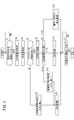
本実施形態における車両制御装置10は、以上のように構成される。続いて、交差点108の通過前後における車両制御装置10の動作について、図2のフローチャートを参照しながら説明する。ここでは、図1の車両制御装置10を搭載した自車両100が、自動運転モードにより走行する場合を想定する。[Operation of vehicle control device 10]
<1. When passing through
The
図2のステップS1において、交差点認識部46は、外界センサ14による検出結果に基づいて、自車両100が直進しながら通過しようとする交差点108(直進交差点)を認識できたか否かを判定する。
In step S1 of FIG. 2, the
図3Aに示すように、自車両100は、一点鎖線矢印で示す走行予定経路102に沿って、第1道路104及び第2道路106が交差する地点(つまり、交差点108)を通過しようとする。本図は、自動車が「左側」走行する旨の取極めがなされている地域の道路を示す。
As shown in FIG. 3A, the
第1道路104及び第2道路106はいずれも、2車線(片側1車線)からなる道路である。第1道路104は、左側から順に、自車両100が走行するレーン(以下、走行レーンL1)と、走行レーンL1に対向するレーンL2とから構成される。
Both the
連続線状のレーンマーク110は、交差点108の手前側にある走行レーンL1と、レーンL2の間の区画線を標示する。連続線状のレーンマーク112は、交差点108の奥側にある走行レーンL1と、レーンL2の間の区画線を標示する。つまり、走行レーンL1は、レーンマーク110、112、路端114、116によって区画されている。
The continuous
なお、破線で示す認識位置P1は、交差点108を初めて認識した時点(認識開始時点)における自車両100の位置である。説明の便宜上、認識開始時点から常に、車両認識部48は2台の先行車両200pを認識し、標示物認識部50はレーンマーク110、112を認識することを想定する。
The recognition position P1 shown by the broken line is the position of the
交差点108が認識されなかった場合(ステップS1:NO)、交差点108が認識されるまでの間、ステップS1に留まる。一方、自車両100が認識位置P1に到達して交差点108が初めて認識された場合(ステップS1:YES)、ステップS2に進む。
If the
ステップS2において、自動運転ECU12は、後述する1次及び2次判定処理に供される各種情報を取得する。この情報は、レーンマーク110、112、路端114、116の位置情報、認識された物体(例えば、先行車両200p)の種別、位置又は動きが含まれる。
In step S2, the
ステップS3において、レーン判定部54は、自車両100の走行レーンL1が、オフセットレーンであるか否かに関する1次判定処理を行う。ここで、「オフセットレーン」とは、交差点108の手前側と奥側で左右方向にずれるレーンを意味する。ナビゲーション装置16の衛星測位装置による自己位置の認識精度が低い場合、交差点108の周辺位置を示す地図情報を参照することで、この1次判定処理を行う。
In step S3, the
具体的には、レーン判定部54は、[1]第1道路104が片側複数車線(特に、3車線以上)であると認識した場合、又は[2]走行レーンL1がオフセットレーンである旨が地図情報に示唆されている場合、オフセットレーンの可能性があると判定する。
Specifically, the
ステップS4において、レーン判定部54は、走行レーンL1がオフセットレーンである可能性を判定する。例えば、図3Aの交差点108に関して可能性がないと判定された場合(ステップS4:NO)、ステップS5に進む。
In step S4, the
ステップS5において、レーン判定部54は、走行レーンL1のオフセットがない前提の下、走行レーンL1の形状を特定するための2本の境界線Br、Bl(仮想区画線Er、Elを含む)を設定する。
In step S5, the
図3Bに示すように、右側の境界線Brは、レーンマーク110(図3A)が標示する手前側区画線Crと、レーンマーク112(図3A)が標示する奥側区画線Drと、手前側区画線Cr及び奥側区画線Drを接続する仮想区画線Erとから構成される。この仮想区画線Erは、交差点108内に設定される仮想線であり、直線形状を有する。
As shown in FIG. 3B, the right boundary line Br is the front side marking line Cr marked by the lane mark 110 (FIG. 3A), the back side marking line Dr marked by the lane mark 112 (FIG. 3A), and the front side. It is composed of a lane marking Cr and a virtual lane marking Er connecting the back lane marking Dr. This virtual lane marking Er is a virtual line set in the
また、左側の境界線Blは、路端114(図3A)により特定される手前側区画線Clと、路端116(図3A)により特定される奥側区画線Dlと、手前側区画線Cl及び奥側区画線Dlを接続する仮想区画線Elとから構成される。この仮想区画線Elは、交差点108内に設定される仮想線であり、直線形状を有する。
Further, the left boundary line Bl is a front side division line Cl specified by the roadside 114 (FIG. 3A), a back side division line Dl specified by the roadside 116 (FIG. 3A), and a front side division line Cl. And a virtual lane marking El connecting the back lane marking Dl. This virtual lane marking El is a virtual line set in the
ステップS6において、走行制御部44(車線維持制御部58)は、自車両100が実行位置P2(図3B)に到達した時点から、走行レーンL1に対するLKAS制御を行う。具体的には、車線維持制御部58は、ステップS5で設定された2本の仮想区画線Er、Elから交差点108内の目標軌道(例えば、中心線)を決定し、この目標軌道に沿って自車両100を走行させる制御を行う。これにより、自車両100は、交差点108内を円滑に走行しながら、奥側の走行レーンL1に進入することができる。
In step S6, the travel control unit 44 (lane keeping control unit 58) performs LKAS control on the travel lane L1 from the time when the
ステップS7において、自動運転ECU12は、自車両100が交差点108を通過したか否かを判定する。交差点108を未だ通過していない場合(ステップS7:NO)、交差点108を通過するまでの間、ステップS7に留まる。一方、交差点108を通過した場合(ステップS7:YES)、図2のフローチャートの実行(交差点108への対処制御)を終了する。
In step S7, the automatic driving
<2.交差点126を通過する場合>
続いて、図3Aとは異なる交差点126(図5)への対処制御について、図2及び図4のフローチャートの他、図5〜図10を参照しながら説明する。<2. When passing through
Subsequently, the coping control for the intersection 126 (FIG. 5) different from that of FIG. 3A will be described with reference to FIGS. 5 to 10 in addition to the flowcharts of FIGS. 2 and 4.
図5に示すように、自車両100は、一点鎖線矢印で示す走行予定経路120に沿って、第1道路122及び第2道路124が交差する地点(つまり、交差点126)を通過しようとする。本図は、図3Aと同様に、自動車が「左側」走行する旨の取極めがなされている地域の道路を示す。
As shown in FIG. 5, the
第1道路122は3車線からなる変則的な道路であり、第2道路124は2車線(片側1車線)からなる道路である。交差点126に対して手前側の第1道路122は、左側から順に、左折専用のレーンL3と、自車両100が走行するレーン(以下、走行レーンL4)と、走行レーンL4に対向するレーンL5とから構成される。交差点126に対して奥側の第1道路122は、左側から順に、自車両100が走行する走行レーンL4と、走行レーンL4に対向するレーンL5と、左折専用のレーンL6とから構成される。
The
破線状のレーンマーク130は、交差点126の手前側にあるレーンL3と、走行レーンL4の間の区画線を標示する。連続線状のレーンマーク131は、交差点126の手前側にある走行レーンL4と、レーンL5の間の区画線を標示する。連続線状のレーンマーク132は、交差点126の奥側にある走行レーンL4と、レーンL5の間の区画線を標示する。破線状のレーンマーク133は、交差点126の奥側にあるレーンL5と、レーンL6の間の区画線を標示する。
The broken
本図から理解されるように、交差点126は、オフセットレーン(L4、L5)を含むオフセット交差点である。自車両100の走行レーンL4は、レーンマーク130、131、132、路端134によって区画されている。つまり、走行レーンL4は、交差点126の奥側が、手前側に対してちょうど1レーン分だけ左方向にずれるオフセットレーンである。なお、オフセット交差点の形態は図5に示す例に限られず、オフセット量が1レーン未満である等、様々な形態が想定される。
As can be understood from this figure, the
図2のフローチャートに示す1次判定処理(ステップS3)の結果、図5の走行レーンL4に関してオフセットレーンの可能性があると判定されたとする。この場合(ステップS4:YES)、ステップS8に進む。 As a result of the primary determination process (step S3) shown in the flowchart of FIG. 2, it is assumed that it is determined that there is a possibility of an offset lane with respect to the traveling lane L4 of FIG. In this case (step S4: YES), the process proceeds to step S8.
ステップS8において、レーン判定部54は、自車両100の走行レーンL4が、オフセットレーンであるか否かに関する2次判定処理を行う。以下、2次判定処理の具体的方法について、図4のフローチャートを参照しながら詳細に説明する。
In step S8, the
図4のステップS81において、レーン判定部54は、手前側区画線Cr、Clに対して少なくとも連続性を保つ外挿処理を施すことで、2本の境界線Br、Bl(つまり、2本の仮想区画線Er、El)を仮設定する。例えば、手前側区画線Cr、Clが直線状である場合(図5参照)、レーン判定部54は、手前側区画線Cr、Clを奥側に向けてそのまま延長する外挿処理を行う。
In step S81 of FIG. 4, the
図6は、図5の交差点126内にて仮想区画線Er、Elを仮設定した結果を示す図である。なお、図示の便宜上、レーンマーク130−133を省略して表記する場合がある。以下の図7A、図7B及び図8についても同様である。
FIG. 6 is a diagram showing the results of provisionally setting the virtual marking lines Er and El in the
図6に示すように、右側の境界線Brは、レーンマーク131(図5)に対応する手前側区画線Crと、レーンマーク133(図5)に対応する奥側区画線Drと、手前側区画線Cr及び奥側区画線Drを接続する仮想区画線Erとから構成される。左側の境界線Blは、レーンマーク130(図5)に対応する手前側区画線Clと、レーンマーク132(図5)に対応する奥側区画線Dlと、手前側区画線Cl及び奥側区画線Dlを接続する仮想区画線Elとから構成される。 As shown in FIG. 6, the right boundary line Br corresponds to the front side marking line Cr corresponding to the lane mark 131 (FIG. 5), the back side marking line Dr corresponding to the lane mark 133 (FIG. 5), and the front side. It is composed of a lane marking Cr and a virtual lane marking Er connecting the back lane marking Dr. The left boundary line Bl is the front side division line Cl corresponding to the lane mark 130 (FIG. 5), the back side division line Dl corresponding to the lane mark 132 (FIG. 5), the front side division line Cl, and the back side division. It is composed of a virtual lane marking El connecting the line Dl.
このように、ちょうど1レーン分だけ左方向にずれるオフセットレーンでは、手前側区画線Cr、Clを単純に外挿した結果、区画線同士の接続を誤った境界線Br、Blが得られる点に留意する。 In this way, in the offset lane that is shifted to the left by exactly one lane, as a result of simply extrapolating the front side marking lines Cr and Cl, the boundary lines Br and Bl that are erroneously connected to each other can be obtained. pay attention to.
ステップS82において、レーン判定部54は、特定の位置関係を満たす前方他車両があるか否かを判別する。具体的には、レーン判定部54は、前方他車両の少なくとも一部が、仮想区画線Er(仮想区画線El)に対して自車両100と同じ側にあるか否かを判別する。特定の位置関係を満たす前方他車両がある場合(ステップS82:YES)、ステップS83に進む。
In step S82, the
ステップS83において、レーン判定部54は、絶対速度又は相対速度を用いた公知の判別手法を用いて、前方他車両が先行車両200pであるか否かを判別する。先行車両200pであると判別された場合(ステップS83:YES)、「ケース2」を選択し(ステップS84)、2次判定処理の実行を終了する。一方、先行車両200pではないと判別された場合(ステップS83:NO)、「ケース1」を選択し(ステップS85)、2次判定処理の実行を終了する。
In step S83, the
ところで、ステップS82に戻って、特定の位置関係を満たす前方他車両がない場合(ステップS82:NO)、ステップS86に進む。 By the way, returning to step S82, if there is no other vehicle in front that satisfies the specific positional relationship (step S82: NO), the process proceeds to step S86.
ステップS86において、レーン判定部54は、特定の位置関係を満たす停止線138があるか否かを判別する。具体的には、レーン判定部54は、停止線138の少なくとも一部が、[1]交差点126の奥側にあり、かつ、[2]仮想区画線Er(仮想区画線El)に対して自車両100と同じ側にあるか否かを判別する。
In step S86, the
停止線138があると判別された場合(ステップS86:YES)、「ケース1」を選択し(ステップS85)、2次判定処理の実行を終了する。一方、停止線138がないと判別された場合(ステップS86:NO)、「ケース3」を選択し(ステップS87)、2次判定処理の実行を終了する。
If it is determined that there is a stop line 138 (step S86: YES), "
図7Aの状況下において、特定物体(前方他車両)の略全体が、左側の仮想区画線El(左側の境界線Bl)に対して自車両100と同じ側にある。また、前方他車両の移動方向は、自車両100の移動方向と概ね一致している。この場合、前方他車両が先行車両200pであると判定され、「ケース2」が選択される。
Under the situation of FIG. 7A, substantially the entire specific object (other vehicle in front) is on the same side as the
図7Bの状況下において、特定物体(前方他車両)の全体が、右側の仮想区画線Er(右側の境界線Br)に対して自車両100と同じ側にある。また、前方他車両の移動方向は、自車両100の移動方向と概ね逆になっている。そうすると、この特定物体が対向車両200oであると判定され、「ケース1」が選択される。
Under the situation of FIG. 7B, the entire specific object (other vehicle in front) is on the same side as the
図8の状況下において、2つの特定物体(位置が異なる2本の停止線)の全体が、右側の仮想区画線Er(右側の境界線Br)に対して自車両100と同じ側にある。そうすると、一方の特定物体が奥側の停止線138であると判定され、「ケース1」が選択される。
Under the situation of FIG. 8, the entire two specific objects (two stop lines having different positions) are on the same side as the
図2のフローチャートに戻って、ステップS9において、自動運転ECU12は、ステップS8での判定結果に応じて異なる動作を行う。自車両100がオフセットレーンを走行中である「ケース1」が選択された場合(ステップS9:ケース1)、ステップS10に進む。
Returning to the flowchart of FIG. 2, in step S9, the
ステップS10において、レーン判定部54は、走行レーンL4のオフセットがある前提の下、走行レーンL4の形状を特定するための2本の境界線Br、Bl(仮想区画線Er、Elを含む)を設定する。ここで、レーン判定部54は、オフセット方向に最も近い奥側区画線Dr、Dlと接続し直すことで仮想区画線Er、Elを設定する。なお、オフセット方向は、自動車が「左側」走行する旨の取極めがなされている地域の道路では「左方向」である。
In step S10, the
図9Aは、図7Bの状況下での自車両100の走行挙動を示す図である。図9Bは、図8の状況下での自車両100の走行挙動を示す図である。図9A及び図9Bのいずれの場合も、レーンマーク131とレーンマーク132を接続した仮想区画線Erが、レーンマーク130と路端134を接続した仮想区画線Elがそれぞれ新たに設定される。ここでは、仮想区画線Er、Elは、滑らかな曲線であるが、これに代わって、直線、又は直線及び曲線の組み合わせであってもよい。
FIG. 9A is a diagram showing the running behavior of the
その後、ステップS6に進んで、走行制御部44(車線維持制御部58)は、自車両100が実行位置P2(図9A及び図9B)に到達した時点から、走行レーンL4に対するLKAS制御を行う。具体的には、車線維持制御部58は、ステップS10で設定された2本の仮想区画線Er、Elから交差点126内の目標軌道(例えば、中心線)を決定し、この目標軌道に沿って自車両100を走行させる制御を行う。これにより、自車両100は、交差点126内を円滑に走行しながら、奥側の走行レーンL4に進入することができる。
After that, in step S6, the travel control unit 44 (lane keeping control unit 58) performs LKAS control on the travel lane L4 from the time when the
一方、ステップS9に戻って、先行車両200pが走行レーンL4上を走行中である「ケース2」が選択された場合(ステップS9:ケース2)、ステップS11に進む。
On the other hand, returning to step S9, when "
ステップS11において、走行制御部44(追従制御部60)は、自車両100が実行位置P2(図10)に到達した時点から、先行車両200pに対するACC制御を行う。具体的には、追従制御部60は、破線矢印で示す先行車両200pの走行軌道140に沿って追従するように、自車両100を走行させる制御を行う。
In step S11, the travel control unit 44 (follow-up control unit 60) performs ACC control on the preceding
図10は、図7Aの状況下での自車両100の走行挙動を示す図である。このように、自車両100は、先行車両200pに追従しながら、奥側の走行レーンL4に進入することができる。
FIG. 10 is a diagram showing the running behavior of the
一方、ステップS9に戻って、ケース1、2とは異なる「ケース3」が選択された場合(ステップS9:ケース3)、ステップS12に進む。
On the other hand, when returning to step S9 and selecting "
ステップS12において、交差点対処部42(引継要求部56)は、自動運転から手動運転に引き継がせるように対処する。具体的には、引継要求部56は、ドライバに対して手動運転への引き継ぎ(テイクオーバー操作)を要求する動作を行う。
In step S12, the intersection coping unit 42 (takeover requesting unit 56) takes measures so that the automatic operation can be taken over by the manual operation. Specifically, the
そうすると、報知装置30は、引継要求部56からの報知指令に応じて、ドライバに対して引き継ぎを行うべき旨を報知する。この要求制御から報知動作までの一連の動作のことを「TOR」(テイクオーバーリクエスト)という。
Then, the
車両制御装置10は、ドライバによるテイクオーバー操作を受け付けた場合、自動運転モードから手動運転モードに切り替える。その後、ドライバは、操作デバイス20を用いて、交差点126を直進するための手動運転を行う。
When the
このように、引継要求部56は、認識処理部40が特定物体(対向レーンL5上にあるべき物体であり、例えば、対向車両200o、停止線136)及び先行車両200pを認識できなかった場合、自車両100のドライバに対して手動運転への引き継ぎを要求する動作を行ってもよい。これにより、走行レーンL4の接続性を判断し難い状況において、運転主体をドライバに円滑に引き継がせることができる。
In this way, when the
なお、車両制御装置10は、要求制御と併せて又はこれとは別に、報知装置30によってドライバに対して警告する報知制御、走行制御部44によって自車両100を減速させ、停止線136の位置で停止させる走行制御を行ってもよい。
In addition, the
[車両制御装置10による効果]
以上のように、車両制御装置10は、自車両100の走行制御を少なくとも部分的に自動で行う装置であって、[1]自車両100が直進しながら通過しようとする交差点108、126を認識する認識処理部40と、[2]自車両100の走行レーンL1、L4が、認識された交差点108、126の手前側と奥側で左右方向にずれるオフセットレーンであるか否かを判定するレーン判定部54と、[3]レーン判定部54による判定結果に応じて異なる走行制御を行う走行制御部44と、を備える。[Effect of vehicle control device 10]
As described above, the
また、車両制御装置10を用いる車両制御方法は、[1]自車両100が直進しながら通過しようとする交差点108、126を認識する認識ステップ(S1)と、[2]自車両100の走行レーンL1、L4が、認識された交差点108、126の手前側と奥側で左右方向にずれるオフセットレーンであるか否かを判定する判定ステップ(S3、S5)と、[3]判定ステップでの判定結果に応じて異なる走行制御を行う制御ステップ(S6、S11、S12)と、を備える。
Further, the vehicle control method using the
このように、オフセットレーンに関する判定結果に応じて異なる走行制御を行うことで、交差点108、126の前後方向における走行レーンL1、L4の接続性に留意しつつ、交差点108、126の直進通過に適切に対処することができる。
In this way, by performing different travel control according to the determination result regarding the offset lane, it is appropriate for passing straight through the
また、認識処理部40は、走行レーンL1、L4の区画線を標示するレーンマーク110、112、130−133をさらに認識し、レーン判定部54は、レーンマーク110、112、130−133により特定される交差点108、126の手前側区画線Cr、Clを外挿することで交差点108、126内の仮想区画線Er、Elを設定し、走行レーンL1、L4がオフセットレーンであるか否かを仮想区画線Er、Elに基づいて判定してもよい。
Further, the
また、レーン判定部54は、走行レーンL1、L4がオフセットレーンであると判定した場合、オフセット方向に最も近い奥側区画線Dr、Dlと接続し直すことで仮想区画線Er、Elを設定してもよい。
Further, when the
また、走行制御部44は、交差点108、126内にて、レーン判定部54により設定された仮想区画線Er、Elに対するLKAS制御(車線維持制御)を行ってもよい。
Further, the
また、認識処理部40は、自車両100の前方にある1つ又は複数の特定物体をさらに認識し、レーン判定部54は、特定物体の少なくとも一部が、仮想区画線Er、Elに対して自車両100と同じ側にある場合、走行レーンL4がオフセットレーンであると判定してもよい。これにより、隣のレーン(つまり、対向レーンL5)に存在し得る特定物体との位置関係を手掛かりにして確度が高い判定を行うことができる。
Further, the
また、認識処理部40は、特定物体として、自車両100の前方にある対向車両200o及び/又は交差点126の奥側にある停止線138を認識してもよい。
Further, the
また、認識処理部40は、自車両100の前方にある先行車両200pをさらに認識し、走行制御部44は、認識処理部40が先行車両200pを認識できた場合、交差点126内にて先行車両200pに対するACC制御(追従制御)を行ってもよい。これにより、走行レーンL4の接続性を意識することなく、先行車両200pの挙動に従って交差点126を通過することができる。
Further, the
また、車両制御装置10は、認識処理部40が特定物体及び先行車両200pを認識できなかった場合、自車両100のドライバに対して手動運転への引き継ぎを要求する動作を行う引継要求部56をさらに備えてもよい。これにより、走行レーンL4の接続性を判断し難い状況において、運転主体をドライバに円滑に引き継がせることができる。
Further, the
また、レーン判定部54は、走行レーンL4がオフセットレーンであると判定した場合、交差点126の手前側区画線Cr、Clと、該手前側区画線Cr、Clに対してオフセット方向に最も近い奥側区画線Dr、Dlを接続することで交差点126内の仮想区画線Er、Elを設定してもよい。
When the
[備考]
なお、この発明は、上述した実施形態に限定されるものではなく、この発明の主旨を逸脱しない範囲で自由に変更できることは勿論である。或いは、技術的に矛盾が生じない範囲で各々の構成を任意に組み合わせてもよい。[remarks]
It should be noted that the present invention is not limited to the above-described embodiment, and of course, it can be freely changed without departing from the gist of the present invention. Alternatively, each configuration may be arbitrarily combined as long as there is no technical contradiction.
Claims (9)
前記自車両(100)が直進しながら通過しようとする交差点(108、126)を認識する認識処理部(40)と、
前記自車両(100)の走行レーン(L1、L4)が、前記認識処理部(40)により認識された前記交差点(108、126)の手前側の前記自車両(100)の走行レーン(L4)に対して前記交差点(108、126)の奥側の走行レーン(L4)が1レーン分だけ左右方向にずれた対向車両(200o)が走行し得るオフセットレーンであるか否かを判定し、前記奥側の走行レーン(L4)が、前記対向車両(200o)が走行し得る前記オフセットレーンであると判定した場合、前記交差点(126)の手前側区画線(Cr、Cl)と、該手前側区画線(Cr、Cl)に対してオフセット方向に最も近い奥側区画線(Dr、Dl)を接続することで前記交差点(126)内の仮想区画線(Er、El)を設定するレーン判定部(54)と、
前記レーン判定部(54)による判定結果に応じて異なる走行制御を行う走行制御部(44)と、
を備えることを特徴とする車両制御装置(10)。 A vehicle control device (10) that automatically controls the running of the own vehicle (100) at least partially.
The recognition processing unit (40) that recognizes the intersections (108, 126) that the own vehicle (100) tries to pass while traveling straight,
The traveling lane (L1, L4) of the own vehicle (100) is the traveling lane (L4) of the own vehicle (100) on the front side of the intersection (108, 126) recognized by the recognition processing unit (40). the far side of the traveling lane of the intersection (108,126) (L4), it is determined whether or not 1 oncoming vehicle offset in the lateral direction by lanes minute (200o) are offset lane that give traveling against, When it is determined that the traveling lane (L4) on the back side is the offset lane on which the oncoming vehicle (200o) can travel , the front side lane markings (Cr, Cl) of the intersection (126) and the front side. Lane determination to set a virtual division line (Er, El) in the intersection (126) by connecting the inner division line (Dr, Dl) closest to the side division line (Cr, Cl) in the offset direction. Department (54) and
A travel control unit (44) that performs different travel control according to a determination result by the lane determination unit (54).
A vehicle control device (10).
前記認識処理部(40)は、前記走行レーン(L1、L4)の区画線(Cr、Cl、Dr、Dl)を標示するレーンマーク(110、112、130−133)をさらに認識し、
前記レーン判定部(54)は、前記レーンマーク(110、112、130−133)により特定される前記交差点(108、126)の手前側区画線(Cr、Cl)を外挿することで前記交差点(108、126)内の仮想区画線(Er、El)を設定し、前記走行レーン(L1、L4)が前記オフセットレーンであるか否かを前記仮想区画線(Er、El)に基づいて判定する
ことを特徴とする車両制御装置(10)。 In the vehicle control device (10) according to claim 1,
The recognition processing unit (40) further recognizes the lane marks (110, 112, 130-133) marking the lane markings (Cr, Cl, Dr, Dl) of the traveling lanes (L1, L4).
The lane determination unit (54) extrapolates the front side division line (Cr, Cl) of the intersection (108, 126) specified by the lane mark (110, 112, 130-133) to the intersection. The virtual lane markings (Er, El) in (108, 126) are set, and whether or not the traveling lanes (L1, L4) are the offset lanes is determined based on the virtual lane markings (Er, El). Vehicle control device (10).
前記レーン判定部(54)は、前記走行レーン(L4)が前記オフセットレーンであると判定した場合、オフセット方向に最も近い奥側区画線(Dr、Dl)と接続し直すことで前記仮想区画線(Er、El)を設定することを特徴とする車両制御装置(10)。 In the vehicle control device (10) according to claim 2.
When the lane determination unit (54) determines that the traveling lane (L4) is the offset lane, the lane determination unit (54) reconnects with the back side division line (Dr, Dl) closest to the offset direction, thereby causing the virtual division line. A vehicle control device (10), characterized in that (Er, El) is set.
前記走行制御部(44)は、前記交差点(108、126)内にて、前記レーン判定部(54)により設定された前記仮想区画線(Er、El)に対する車線維持制御を行うことを特徴とする車両制御装置(10)。 In the vehicle control device (10) according to claim 2 or 3.
The traveling control unit (44) is characterized in that it performs lane keeping control on the virtual lane markings (Er, El) set by the lane determination unit (54) within the intersections (108, 126). Vehicle control device (10).
前記認識処理部(40)は、前記自車両(100)の前方にある1つ又は複数の特定物体(138、200o)をさらに認識し、
前記レーン判定部(54)は、前記特定物体(138、200o)の少なくとも一部が、前記仮想区画線(Er、El)に対して前記自車両(100)と同じ側にある場合、前記走行レーン(L4)が前記オフセットレーンであると判定する
ことを特徴とする車両制御装置(10)。 In the vehicle control device (10) according to claim 2.
The recognition processing unit (40) further recognizes one or a plurality of specific objects (138, 200o) in front of the own vehicle (100), and further recognizes the specific object (138, 200o).
When at least a part of the specific object (138, 200o) is on the same side as the own vehicle (100) with respect to the virtual division line (Er, El), the lane determination unit (54) travels. The vehicle control device (10), characterized in that the lane (L4) is determined to be the offset lane.
前記認識処理部(40)は、前記特定物体(138、200o)として、前記自車両(100)の前方にある対向車両(200o)及び/又は前記交差点(126)の奥側にある停止線(138)を認識することを特徴とする車両制御装置(10)。 In the vehicle control device (10) according to claim 5.
The recognition processing unit (40), as the specific object (138, 200o), is an oncoming vehicle (200o) in front of the own vehicle (100) and / or a stop line (126) behind the intersection (126). A vehicle control device (10) characterized by recognizing 138).
前記認識処理部(40)は、前記自車両(100)の前方にある先行車両(200p)をさらに認識し、
前記走行制御部(44)は、前記認識処理部(40)が前記先行車両(200p)を認識できた場合、前記交差点(126)内にて前記先行車両(200p)に対する追従制御を行う
ことを特徴とする車両制御装置(10)。 In the vehicle control device (10) according to claim 5 or 6.
The recognition processing unit (40) further recognizes the preceding vehicle (200p) in front of the own vehicle (100), and further recognizes the preceding vehicle (200p).
When the recognition processing unit (40) can recognize the preceding vehicle (200p), the traveling control unit (44) performs follow-up control with respect to the preceding vehicle (200p) within the intersection (126). A characteristic vehicle control device (10).
前記認識処理部(40)が前記特定物体(138、200o)及び前記先行車両(200p)を認識できなかった場合、前記自車両(100)のドライバに対して手動運転への引き継ぎを要求する動作を行う引継要求部(56)をさらに備えることを特徴とする車両制御装置(10)。 In the vehicle control device (10) according to claim 7.
When the recognition processing unit (40) cannot recognize the specific object (138, 200o) and the preceding vehicle (200p), an operation of requesting the driver of the own vehicle (100) to take over to manual driving. A vehicle control device (10), further comprising a takeover request unit (56) for performing the above.
前記自車両(100)が直進しながら通過しようとする交差点(108、126)を認識する認識ステップと、
前記自車両(100)の走行レーン(L1、L4)が、認識された前記交差点(108、126)の手前側の前記自車両(100)の走行レーン(L4)に対して前記交差点(108、126)の奥側の走行レーン(L4)が1レーン分だけ左右方向にずれた対向車両(200o)が走行し得るオフセットレーンであるか否かを判定し、前記奥側の走行レーン(L4)が、前記対向車両(200o)が走行し得る前記オフセットレーンであると判定した場合、前記交差点(126)の手前側区画線(Cr、Cl)と、該手前側区画線(Cr、Cl)に対してオフセット方向に最も近い奥側区画線(Dr、Dl)を接続することで前記交差点(126)内の仮想区画線(Er、El)を設定する判定ステップと、
前記判定ステップでの判定結果に応じて異なる走行制御を行う制御ステップと、
を備えることを特徴とする車両制御方法。 A vehicle control method using a vehicle control device (10) that automatically controls the running of the own vehicle (100) at least partially.
The recognition step of recognizing the intersections (108, 126) that the own vehicle (100) is going to pass while going straight,
The traveling lane (L1, L4) of the own vehicle (100) is the intersection (108, L4) with respect to the traveling lane (L4) of the own vehicle (100) on the front side of the recognized intersection (108, 126). 126) back side of the travel lane (L4), it is determined whether the oncoming vehicle offset in the lateral direction by one lane minute (200o) are offset lane that give traveling of the rear side of the traveling lane (L4 ) Is the offset lane on which the oncoming vehicle (200o) can travel , the front lane markings (Cr, Cl) of the intersection (126) and the front lane markings (Cr, Cl). A determination step of setting a virtual lane marking (Er, El) in the intersection (126) by connecting the back lane marking (Dr, Dl) closest to the offset direction.
A control step that performs different running control according to the judgment result in the judgment step, and
A vehicle control method comprising.
Applications Claiming Priority (1)
| Application Number | Priority Date | Filing Date | Title |
|---|---|---|---|
| PCT/JP2017/013321 WO2018179252A1 (en) | 2017-03-30 | 2017-03-30 | Vehicle control apparatus and vehicle control method |
Publications (2)
| Publication Number | Publication Date |
|---|---|
| JPWO2018179252A1 JPWO2018179252A1 (en) | 2019-11-21 |
| JP6907304B2 true JP6907304B2 (en) | 2021-07-21 |
Family
ID=63674440
Family Applications (1)
| Application Number | Title | Priority Date | Filing Date |
|---|---|---|---|
| JP2019508035A Active JP6907304B2 (en) | 2017-03-30 | 2017-03-30 | Vehicle control device and vehicle control method |
Country Status (4)
| Country | Link |
|---|---|
| US (1) | US20200051436A1 (en) |
| JP (1) | JP6907304B2 (en) |
| CN (1) | CN110494903A (en) |
| WO (1) | WO2018179252A1 (en) |
Families Citing this family (9)
| Publication number | Priority date | Publication date | Assignee | Title |
|---|---|---|---|---|
| JP6935507B2 (en) * | 2018-12-26 | 2021-09-15 | バイドゥ ドットコム タイムス テクノロジー (ベイジン) カンパニー リミテッド | Mutual avoidance algorithm for self-reversing lines for autonomous driving |
| JP7258284B2 (en) * | 2019-04-19 | 2023-04-17 | マツダ株式会社 | vehicle controller |
| JP7358990B2 (en) * | 2020-01-06 | 2023-10-11 | トヨタ自動車株式会社 | Self-driving car management system, management device, management method, self-driving car, and program |
| CN112537298A (en) * | 2020-11-30 | 2021-03-23 | 南通路远科技信息有限公司 | Automatic lane generation method and device and traffic vehicle |
| JP7256216B2 (en) * | 2021-02-25 | 2023-04-11 | 本田技研工業株式会社 | VEHICLE CONTROL DEVICE, VEHICLE CONTROL METHOD, AND PROGRAM |
| US12097858B2 (en) | 2021-03-17 | 2024-09-24 | Nissan Motor Co., Ltd. | Travel control method and travel control device for vehicle |
| JP7788045B2 (en) * | 2021-11-08 | 2025-12-18 | 日産自動車株式会社 | Vehicle driving control method and driving control device |
| DE102022116643A1 (en) | 2022-07-04 | 2024-01-04 | Bayerische Motoren Werke Aktiengesellschaft | METHOD AND DEVICE FOR CONTROLLING A TRANSVERSE GUIDE OF A MOTOR VEHICLE |
| DE102023129269A1 (en) * | 2023-10-24 | 2025-04-24 | Bayerische Motoren Werke Aktiengesellschaft | Method for operating a lane guidance assistant of a vehicle in road sections without lane markings, lane guidance assistant and vehicle |
Family Cites Families (16)
| Publication number | Priority date | Publication date | Assignee | Title |
|---|---|---|---|---|
| DE10149146A1 (en) * | 2001-10-05 | 2003-04-17 | Bosch Gmbh Robert | Speed regulator with distance regulating function for motor vehicle, has monitoring module for detecting situation with danger of objects not detected by location system being in immediate vicinity |
| JP4888761B2 (en) * | 2005-10-31 | 2012-02-29 | 株式会社エクォス・リサーチ | Virtual lane display device |
| JP4692448B2 (en) * | 2006-09-12 | 2011-06-01 | 株式会社デンソー | Vehicle driving support system, vehicle driving support device, and in-vehicle device |
| JP2010002953A (en) * | 2008-06-18 | 2010-01-07 | Mazda Motor Corp | Lane departure alarm device of vehicle |
| JP5169740B2 (en) * | 2008-10-30 | 2013-03-27 | アイシン・エィ・ダブリュ株式会社 | Road information guidance device, road information guidance method, and road information guidance program |
| US8996226B1 (en) * | 2011-07-12 | 2015-03-31 | Google Inc. | Intersection completer |
| EP2871107B1 (en) * | 2012-07-06 | 2023-10-25 | Toyota Jidosha Kabushiki Kaisha | Traveling control device for vehicle |
| JP6197393B2 (en) * | 2013-06-20 | 2017-09-20 | 株式会社豊田中央研究所 | Lane map generation device and program |
| CN106103231B (en) * | 2014-03-18 | 2020-08-04 | 日产自动车株式会社 | vehicle operating device |
| JP5831585B2 (en) * | 2014-04-24 | 2015-12-09 | トヨタ自動車株式会社 | Driving support device and driving support method |
| CN104269065B (en) * | 2014-09-29 | 2016-02-24 | 东南大学 | Two-way road and the one way traffic crossing optimization method with reverse public transportation lane |
| JP6445907B2 (en) * | 2015-03-20 | 2018-12-26 | 株式会社Subaru | Vehicle driving support control device |
| JP6361567B2 (en) * | 2015-04-27 | 2018-07-25 | トヨタ自動車株式会社 | Automated driving vehicle system |
| JP6600995B2 (en) * | 2015-06-02 | 2019-11-06 | 株式会社豊田中央研究所 | Vehicle control apparatus and program |
| JP6376059B2 (en) * | 2015-07-06 | 2018-08-22 | トヨタ自動車株式会社 | Control device for autonomous driving vehicle |
| JP6922479B2 (en) * | 2017-07-03 | 2021-08-18 | スズキ株式会社 | Driving support device |
-
2017
- 2017-03-30 JP JP2019508035A patent/JP6907304B2/en active Active
- 2017-03-30 US US16/498,914 patent/US20200051436A1/en not_active Abandoned
- 2017-03-30 WO PCT/JP2017/013321 patent/WO2018179252A1/en not_active Ceased
- 2017-03-30 CN CN201780089180.7A patent/CN110494903A/en active Pending
Also Published As
| Publication number | Publication date |
|---|---|
| CN110494903A (en) | 2019-11-22 |
| JPWO2018179252A1 (en) | 2019-11-21 |
| US20200051436A1 (en) | 2020-02-13 |
| WO2018179252A1 (en) | 2018-10-04 |
Similar Documents
| Publication | Publication Date | Title |
|---|---|---|
| JP6907304B2 (en) | Vehicle control device and vehicle control method | |
| US11180143B2 (en) | Vehicle control device | |
| JP6365390B2 (en) | Lane change support device | |
| JP6630267B2 (en) | Vehicle control device | |
| JP6481670B2 (en) | Automated driving system | |
| JP7739760B2 (en) | Vehicle Driving Assistance Systems | |
| JP6650904B2 (en) | Vehicle control device | |
| US20180129206A1 (en) | Vehicle control device | |
| US20160325750A1 (en) | Travel control apparatus | |
| CN110036426B (en) | Control device and control method | |
| CN106080595B (en) | Controlling device for vehicle running | |
| CN110446641B (en) | Vehicle control device and vehicle control method | |
| CN110171421B (en) | Vehicle control device | |
| JP6817413B2 (en) | Vehicle control device | |
| JP2016132421A (en) | Automatic driving device | |
| JP2019209837A (en) | Drive support control device of vehicle, drive support system and drive support control method | |
| JP2021033772A (en) | Stop line position estimation device and vehicle control system | |
| JP6985176B2 (en) | Vehicle control device | |
| JP6880222B2 (en) | Vehicle control device | |
| CN110194149A (en) | Controller of vehicle | |
| JP7739759B2 (en) | Vehicle Driving Assistance Systems | |
| US12071137B2 (en) | Lane biasing to indicate an intended movement of a vehicle | |
| JP7274314B2 (en) | Platoon automatic operation control device | |
| WO2025257944A1 (en) | Vehicle control method and vehicle control device |
Legal Events
| Date | Code | Title | Description |
|---|---|---|---|
| A621 | Written request for application examination |
Free format text: JAPANESE INTERMEDIATE CODE: A621 Effective date: 20190628 |
|
| A131 | Notification of reasons for refusal |
Free format text: JAPANESE INTERMEDIATE CODE: A131 Effective date: 20200519 |
|
| A521 | Request for written amendment filed |
Free format text: JAPANESE INTERMEDIATE CODE: A523 Effective date: 20200629 |
|
| A131 | Notification of reasons for refusal |
Free format text: JAPANESE INTERMEDIATE CODE: A131 Effective date: 20201117 |
|
| A521 | Request for written amendment filed |
Free format text: JAPANESE INTERMEDIATE CODE: A523 Effective date: 20210118 |
|
| TRDD | Decision of grant or rejection written | ||
| A01 | Written decision to grant a patent or to grant a registration (utility model) |
Free format text: JAPANESE INTERMEDIATE CODE: A01 Effective date: 20210622 |
|
| A61 | First payment of annual fees (during grant procedure) |
Free format text: JAPANESE INTERMEDIATE CODE: A61 Effective date: 20210630 |
|
| R150 | Certificate of patent or registration of utility model |
Ref document number: 6907304 Country of ref document: JP Free format text: JAPANESE INTERMEDIATE CODE: R150 |