JP6957814B2 - Valve set, cup - Google Patents
Valve set, cup Download PDFInfo
- Publication number
- JP6957814B2 JP6957814B2 JP2017145774A JP2017145774A JP6957814B2 JP 6957814 B2 JP6957814 B2 JP 6957814B2 JP 2017145774 A JP2017145774 A JP 2017145774A JP 2017145774 A JP2017145774 A JP 2017145774A JP 6957814 B2 JP6957814 B2 JP 6957814B2
- Authority
- JP
- Japan
- Prior art keywords
- valve
- cup
- plug
- hole
- cup body
- Prior art date
- Legal status (The legal status is an assumption and is not a legal conclusion. Google has not performed a legal analysis and makes no representation as to the accuracy of the status listed.)
- Active
Links
Images


Landscapes
- Table Devices Or Equipment (AREA)
- Details Of Rigid Or Semi-Rigid Containers (AREA)
Description
本発明は、複数の部品を備える弁セットに関する。弁セットは、有底筒状のコップ本体に形成された貫通穴に対し取り付けられるものであって、その内部にパイプを差し込んで液体をコップ本体に入れることのできるものである。また本発明は弁セットに関するだけでなく、その弁セットとコップ本体とを備えるコップに関する。 The present invention relates to a valve set including a plurality of parts. The valve set is attached to a through hole formed in a bottomed cylindrical cup body, and a pipe can be inserted into the valve set to allow liquid to enter the cup body. Further, the present invention relates not only to a valve set but also to a cup including the valve set and a cup body.
コップの一例としては、筒状の胴部の下部外周面に形成された貫通穴に弁を取り付けたものが存在する。弁は開閉可能であり、パイプを差し込めるようになっている。そしてパイプから液体を胴部の内部に注入できるようになっている。 As an example of a cup, there is one in which a valve is attached to a through hole formed in the lower outer peripheral surface of a cylindrical body portion. The valve can be opened and closed so that a pipe can be inserted. And the liquid can be injected into the inside of the body from the pipe.
ところで胴部と弁は別部品であるので、弁の外周面に形成された凹溝と胴部の貫通穴との境目を密接させて、液漏れを防止する必要がある。そして液漏れを防止する困難性は、貫通穴が形成される胴部の条件、例えば胴部の厚み、胴部の形状、胴部における貫通穴の位置等によって変わってくる。 By the way, since the body and the valve are separate parts, it is necessary to bring the boundary between the concave groove formed on the outer peripheral surface of the valve and the through hole of the body into close contact with each other to prevent liquid leakage. The difficulty of preventing liquid leakage varies depending on the conditions of the body portion on which the through hole is formed, for example, the thickness of the body portion, the shape of the body portion, the position of the through hole in the body portion, and the like.
具体的に言えば例えば胴部の厚みが厚いもの、言い換えれば胴部が変形しない程度の厚いものであれば、弁と貫通穴との接触面積が広く、液漏れを防ぎやすい。
しかし胴部の厚みが薄いもの、言い換えれば胴部が弾性変形する程度の薄いものであると、弁と貫通穴との接触面積が狭く、液漏れを防ぎにくい。
Specifically, for example, if the body is thick, in other words, if the body is thick enough not to be deformed, the contact area between the valve and the through hole is wide, and it is easy to prevent liquid leakage.
However, if the body portion is thin, in other words, the body portion is thin enough to be elastically deformed, the contact area between the valve and the through hole is narrow, and it is difficult to prevent liquid leakage.
また別の例を挙げると、貫通穴とその周辺部が胴部の凹凸の無い面、より具体的に言えば平面や曲率の大きな曲面に存在すれば、弁の凹溝は平面等に嵌合されているので、胴部の形状の影響を殆ど受けず、液漏れを防ぎやすい。
また液漏れを防ぐ場合、弁の凹溝の溝幅は貫通穴の厚みに一致させるのが常識である。しかし貫通穴とその周辺部が胴部の凹凸のある面に存在する場合に、弁の凹溝を貫通穴の厚みに一致させてあると、弁の凹溝は、胴部の凹凸に合わせて変形するので、液漏れを防ぎにくいものである。ちなみに胴部の凹凸のある面の形状の一例としては、筒状をなす胴部の下部に口径方向に屈曲する段部が存在し、その段部に対し上側と下側で胴部の口径が異なるような形状である。そして例えば段部に対し上側と下側に亘って貫通穴とその周辺部が存在する場合、液漏れを防ぎにくいものである。
To give another example, if the through hole and its peripheral portion exist on a flat surface of the body, more specifically, on a flat surface or a curved surface having a large curvature, the concave groove of the valve fits on a flat surface or the like. Because it is made, it is hardly affected by the shape of the body, and it is easy to prevent liquid leakage.
Further, when preventing liquid leakage, it is common sense that the groove width of the concave groove of the valve matches the thickness of the through hole. However, if the through hole and its peripheral portion are present on the uneven surface of the body, and the concave groove of the valve is made to match the thickness of the through hole, the concave groove of the valve will be adjusted to the uneven surface of the body. Since it is deformed, it is difficult to prevent liquid leakage. By the way, as an example of the shape of the uneven surface of the body, there is a step part that bends in the caliber direction at the bottom of the cylindrical body, and the caliber of the body is on the upper and lower sides of the step. It has a different shape. Then, for example, when a through hole and a peripheral portion thereof are present on the upper side and the lower side of the step portion, it is difficult to prevent liquid leakage.
本発明は上記実情を考慮して創作されたものであり、その目的は胴部の貫通穴と弁との境目から液漏れをできるだけ防ぐことである。 The present invention has been created in consideration of the above circumstances, and an object of the present invention is to prevent liquid leakage from the boundary between the through hole of the body and the valve as much as possible.
本発明の弁セットは、コップ本体に形成された貫通穴に嵌合すると共に弾性変形可能な弁、弁をその内側から押し広げてコップ本体に止める止め輪を備える。また弁は、貫通穴の内側に嵌合すると共に一端を開口端とする筒状の栓部、栓部の他端側を開閉可能に閉鎖する弁部を備えるものである。前記弁部は、前記栓部のうち当該弁部側から貫通方向に延長する変形部と、前記変形部の先端を閉鎖する弁本体部を備えており、前記変形部は、口径方向の厚みが前記栓部の端部の厚み、および前記弁本体部のうち前記変形部側の厚みよりも薄いものである。そのうえで止め輪は、栓部の内側に嵌合する筒状であり、弁よりも硬いものである。
The valve set of the present invention includes a valve that fits into a through hole formed in the cup body and is elastically deformable, and a retaining ring that spreads the valve from the inside and stops it in the cup body. Further, the valve is provided with a cylindrical plug portion that fits inside the through hole and has one end as an open end, and a valve portion that opens and closes the other end side of the plug portion so as to be openable and closable. The valve portion includes a deformed portion of the plug portion that extends from the valve portion side in the penetrating direction and a valve body portion that closes the tip of the deformed portion, and the deformed portion has a thickness in the caliber direction. It is thinner than the thickness of the end portion of the plug portion and the thickness of the valve body portion on the deformed portion side. On top of that, the retaining ring has a cylindrical shape that fits inside the stopper, and is harder than the valve.
止め輪の具体的な構成の一例は、以下の通りである。
止め輪は、栓部の内側に対し開口端側から挿入する筒状の挿入部、挿入部の貫通方向の両端部のうち栓部に取り付けた状態での開口端側の端部において挿入部の外側に張り出すフランジ部を備えるものである。そのうえで挿入部の外径は、栓部の内径よりも大きいものである。
An example of a specific configuration of the retaining ring is as follows.
Retaining rings are inserted at the end of the tubular insertion part that is inserted from the opening end side into the inside of the plug part, and at both ends of the insertion part in the penetrating direction on the opening end side when attached to the plug part. It is provided with a flange portion that projects outward. On top of that, the outer diameter of the insertion portion is larger than the inner diameter of the plug portion.
また上記した弁セットを用いた本発明のコップは、貫通穴が形成されたコップ本体、貫通穴に嵌合された弁セットを備える。またコップ本体は、筒状であると共に凹凸のある面を含むコップ胴部、コップ胴部の下端を塞ぐコップ底部を備えると共に、弾性変形可能な厚み0.2mm〜0.5mmとしてある。そのうえ弁はコップ胴部の凹凸のある面に存在するものである。 Further, the cup of the present invention using the valve set described above includes a cup body having a through hole formed therein and a valve set fitted in the through hole. Further, the cup body is provided with a cup body including a cylindrical and uneven surface, and a cup bottom that closes the lower end of the cup body, and has a thickness of 0.2 mm to 0.5 mm that can be elastically deformed. Moreover, the valve is present on the uneven surface of the cup body.
コップの一例としては、以下のものが存在する。
すなわちコップ胴部は、その上側を形成する胴上部、その下側を形成する胴下部であってその上端の口径を胴上部の下端の口径よりも小さくしてある胴下部、側面視して胴下部と胴上部とを段状に接合する段部を備えるものである。そのうえで弁の一部は段部に存在するものである。
The following are examples of cups.
That is, the cup body is the upper part of the body forming the upper side thereof, the lower part of the body forming the lower side of the cup body, and the lower part of the body whose upper end is smaller than the diameter of the lower end of the upper part of the body. It is provided with a stepped portion that joins the lower part and the upper part of the body in a stepped manner. On top of that, part of the valve is in the step.
また栓部の具体的な構成は問わないが、凹溝部の弾性変形をできるだけ抑制するには次のようにすることが望ましい。
すなわち栓部は、その外周面には貫通穴をその全周に亘って収容する環状の凹溝部を備えるものとする。そのうえ凹溝部の溝幅は、コップ本体の貫通穴の厚みよりも広くする。
Further, although the specific configuration of the plug portion is not limited, it is desirable to perform the following in order to suppress the elastic deformation of the concave groove portion as much as possible.
That is, the plug portion is provided with an annular recessed groove portion on the outer peripheral surface thereof, which accommodates the through hole over the entire circumference. Moreover, the groove width of the concave groove portion is made wider than the thickness of the through hole of the cup body.
本発明の弁セットは、止め輪を弁よりも硬くし、止め輪によって弁をその内側から押し広げるものなので、コップ本体の貫通穴に栓部を密接させることができ、貫通穴と弁との境目から液漏れがし難くなる。 In the valve set of the present invention, the retaining ring is made harder than the valve, and the valve is expanded from the inside by the retaining ring. Therefore, the stopper can be brought into close contact with the through hole of the cup body, and the through hole and the valve can be connected. It becomes difficult for liquid to leak from the boundary.
また本発明のコップは、コップ本体が弾性変形可能な厚みであるだけでなく、弁がコップ胴部の凹凸のある面に存在するものなので、液漏れを誘発しやすいものである。それにもかかわらず本発明のコップは、凹凸のある面による栓部(凹溝部)の弾性変形を止め輪によってできる限り抑制して、貫通穴に栓部を密接させることができるので、貫通穴と弁との境目から液漏れがし難くなる。 Further, in the cup of the present invention, not only the cup body has a thickness that allows elastic deformation, but also the valve exists on the uneven surface of the cup body, so that liquid leakage is likely to be induced. Nevertheless, in the cup of the present invention, the elastic deformation of the plug portion (concave groove portion) due to the uneven surface can be suppressed as much as possible by the retaining ring, and the plug portion can be brought into close contact with the through hole. It becomes difficult for liquid to leak from the boundary with the valve.
また本発明のコップは、弁が栓部に環状の凹溝部を備えるものとし、凹溝部の溝幅をコップ本体の貫通穴の厚みよりも広いものとすれば、例えば凹溝部の溝幅をコップ本体の貫通穴の厚み以下にしたものと比べて、凹溝部の溝幅と貫通穴の厚みとの関係による栓部(凹溝部)の弾性変形を溝幅の分だけ抑えられるので、貫通穴と弁との境目から液漏れがし難くなる。 Further, in the cup of the present invention, if the valve is provided with an annular concave groove portion in the plug portion and the groove width of the concave groove portion is wider than the thickness of the through hole of the cup body, for example, the groove width of the concave groove portion is used as a cup. Compared to the one with the thickness of the through hole of the main body or less, the elastic deformation of the plug part (concave groove part) due to the relationship between the groove width of the concave groove part and the thickness of the through hole can be suppressed by the groove width, so that the through hole It becomes difficult for liquid to leak from the boundary with the valve.
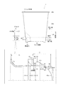
図1に示すように本発明の第一実施形態のコップ1は、貫通穴2aが形成されたコップ本体2、貫通穴2aに固定する弁セット3を備える。
As shown in FIG. 1, the cup 1 of the first embodiment of the present invention includes a cup
弁セット3は、コップ本体2の貫通穴2aに嵌合する弁4、弁4をその内側から押し広げてコップ本体2に止める止め輪7を備える。弁4と止め輪7は筒状であり、本実施形態では筒状の一例としての円筒状である。よって以後、弁4と止め輪7の説明で、筒状と言う場合は、円筒状の意味である。
The
弁4は、弾性変形可能なもので、例えばシリコン製である。また弁4は図1〜3に示すように、貫通穴2aの内側に対しその全周に亘って嵌合する栓部5、栓部5の口径方向内側を弾性によって開閉可能に閉鎖する弁部6を備えるものである。
The
栓部5は、筒状の栓本体部51を備え、栓本体部51の貫通方向の一端部側を開口端側とし、貫通方向の他端側(弁部側)を弁部6によって閉鎖される閉鎖端とする。栓部5は、栓本体部51のほかに、栓本体部51の外周面から口径方向外側にその全周に亘って張り出す第1の外鍔部52と第2の外鍔部53、栓本体部51の内周面から口径方向内側にその全周に亘って張り出す内鍔部54を備える。
The
第1の外鍔部52と第2の外鍔部53とは環状、より詳しくは円環状である。第1の外鍔部52は第2の外鍔部53に対し開口端側に位置し、第2の外鍔部53は第1の外鍔部52に対し閉鎖端側(弁部側)に位置するものとする。また第1の外鍔部52の外径は第2の外鍔部53の外径よりも大きなものである。
また栓部5の口径方向の外周面には第1の外鍔部52と第2の外鍔部53と栓本体部51とで包囲された凹溝部5aが形成される。凹溝部5aは、環状、より詳しくは円環状であり、口径方向外側に向かって開口すると共に、貫通穴2aの周囲をその全周に亘って収容するものである。また凹溝部5aの溝幅5Wは、コップ本体2の貫通穴2aの厚み2tよりも広くしてある。
The first
Further, a
栓本体部51は、内周面のうち開口端側の端部を、止め輪7を差し込むときの入口部51aとしてある。栓本体部51の入口部51aは、開口端から閉鎖端側(弁部側)に向かって小径になる傾斜が付いたものであり、より詳しくは本実施形態では円錐状に直径が減少しているもの、いわゆるテーパー状である。
また栓本体部51は、外周面のうち弁部側の端部を、弁4を貫通穴2aに挿入するときの案内部51bとしてある。案内部51bは、第2の外鍔部53から弁部側に向かって小径になるテーパー状である。
The stopper
Further, the plug
弁部6は、栓部5のうち閉鎖端側から栓部5の貫通方向に延長する変形部61と、変形部61の先端を閉鎖する弁本体部62とを備える。
The
変形部61は筒状である。また口径方向に関する厚みに関して変形部61の厚み61tは、栓部5(栓本体部51から内鍔部54が内側に張り出している部分)のうち変形部側(閉鎖端側)の端部の厚み51t、および弁本体部62のうち変形部側(外周部側)の厚み62tよりも薄くし、それによって変形部61を弾性変形し易くしてある。ちなみに口径方向に関する厚みに関して、弁本体部62と変形部61との境界は、変形部61と同じ厚みであるが、弁本体部62のうち変形部側の部分は、変形部61から離れるにつれて変形部61の厚みより徐々に厚くなっている。
The
弁本体部62は、変形部61の先端を閉鎖する板状、より詳しくは円盤状である。また弁本体部62は栓部5の内部空間側に面する内面62aを備える。内面62aは、その断面形状を弁本体部62の外面に向かって膨らむ円弧状にしてある。言い換えれば、弁本体部62の内面形状は、半球の球面よりも小さな球面形状にしてある。また弁本体部62は栓部5の貫通方向に貫通する切目63を備える。切目63は円盤状である弁本体部62の中心に対して放射状に直径方向に延長している。なお通常は切目63は弁自身の弾性によって閉じている。
このような弁4の栓部5の口径方向内側に嵌合するものが止め輪7である。
The
The retaining
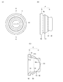
止め輪7は、弁4よりも硬いもので、例えばポリプロピレン製である。
また止め輪7は図1,2,4に示すように、栓部5の口径方向内側に対し開口端側から挿入する筒状の挿入部71、挿入部71の筒状の両端部のうち栓部5に取り付けた状態での開口端側の端部において挿入部71の口径方向外側に張り出すフランジ部72を備える。
The retaining
Further, as shown in FIGS. A
挿入部71は、その外周面を栓部5の栓本体部51の内周面と同形状にした筒状である。また挿入部71は、その貫通方向のうちフランジ部側の端部を、液体注入用のパイプPを差し込むときの入口部71aとしてある。挿入部71の入口部71aは、フランジ部72に向かうにつれて大径になるテーパー状である。また挿入部71のうち入口部以外の部分の外径71Dは、栓本体部51のうち入口部51a以外の部分の内径51Dよりも僅かに大きいもので、それによって栓本体部51の口径方向内側に挿入部71を嵌合させたときに栓本体部51を口径方向外側に押し広げるものである。
フランジ部72は環状、より詳しくは円環状である。
このような止め輪7と弁4から構成される弁セット3を固定するのがコップ本体2である。
The
The
It is the
コップ本体2は、筒状、より詳しくは円筒状のコップ胴部21と、コップ胴部21の下端を塞ぐコップ底部25とを備える形状、いわゆる有底筒状である。
またコップ本体2は、プラスチック製であり、硬直性を有しながらも変形可能なもの、つまり少し力を入れてコップ胴部21を持つと凹んで変形し、力を解放すると元の形状に復元する程度の厚みのものである。厚みは0.5mm以下、望ましくは0.3mm以下である。またコップ本体2の厚みの下限値は、望ましくは0.2mmである。
The
The
コップ底部25は板状である。 The bottom 25 of the cup is plate-shaped.
コップ胴部21は凹凸のある面の形状である。より詳しく言えばコップ胴部21は、上から順に、円筒状の胴上部22と、胴上部22の下端の全周からその口径方向内側に向かって張り出す円環状の段部23と、胴上部22に対して小径の円筒状の胴下部24とを備える。
The
胴上部22は、コップ胴部21の上側部分を形成するもので、下方に向かうにつれて小径になるテーパー状である。より詳しくは胴上部22は、テーパー状の胴上部本体22aと、胴上部本体22aの上端部から口径方向外側に張り出す環状のフランジ22bとを備える。
The body
段部23は、口径方向に広がる環状、より詳しくは本実施形態では円環状の板である。コップ本体2を側面視すると、段部23は胴下部24と胴上部22とを段状に接合すると共に胴下部24と胴上部22に対して屈曲するものである。
The
胴下部24は、コップ胴部21の下側部分を形成するもので、口径がほぼ一定の筒状である。
The
上記したコップ胴部21に貫通穴2aが形成されている。貫通穴2aの位置は、弁4の栓部5が段部23によって弾性変形する位置であり、本実施形態では段部23と胴下部24の両方に亘る位置(胴上部22の下端を起点にして下側の位置)である。ちなみに弾性変形する位置とは、本実施形態の例以外には、段部23を中心にして上下に亘る位置、つまり胴上部22と段部23と胴下部24の3つに亘る位置、また胴上部22のうち段部23の近傍の位置、胴下部24うち段部23の近傍の位置、段部23と胴上部22の両方に亘る位置(胴下部24の上端を起点にして上側の位置)である。
A through
貫通穴2aはコップ本体2を側面視して円形である。また貫通穴2aの内径2Dは凹溝部5aの口径5Dよりも僅かに大きいものである。凹溝部5aの口径5Dとは、凹溝部5aの内面のうち口径方向内側を形成する面の口径である。
The through
上記した第一実施形態のコップ1は次のようにして組み立てる。まず貫通穴2aに弁4を挿入する。そうすると貫通穴2aを弁4の案内部51bが通過し、その後、貫通穴2aが第2の外鍔部53を乗り越えて、貫通穴2aの周辺部が第1の外鍔部52に衝突し、貫通穴2aが凹溝部5aに嵌合する。そうすると、貫通穴2aの位置が段部23と胴下部24に亘る位置であるため、貫通穴2aのうち胴上部側は凹溝部5aのうち第1の外鍔部52側に位置し、貫通穴2aのうち胴下部側は凹溝部5aのうち第2の外鍔部53側に位置することになる。またこのとき、貫通穴2aの内径2Dが凹溝部5aの口径5Dよりも僅かに大きいので、貫通穴2aと凹溝部5aとは口径方向に僅かに隙間のある状態になっている。
2)次に弁4の内側に止め輪7を挿入する。そうすると、止め輪7の挿入部71の外径71Dが弁4の栓本体部51の内径51Dよりも僅かに大きいことから、栓本体部51が口径方向外側に弾性変形して押し広げられ、貫通穴2aと凹溝部5aとは口径方向に密接する。
The cup 1 of the first embodiment described above is assembled as follows. First, the
2) Next, the retaining
上記した第一実施形態のコップ1に関して弁セット3は、以下の効果を有する。
貫通穴2aの内径2Dを栓部5の凹溝部5aの口径5Dよりも僅かに大きくしてあるので、弁4を貫通穴2aに嵌合させただけでは、貫通穴2aと栓部5の凹溝部5aとは口径方向に隙間のある状態となっている。ただし弁の内側に止め輪7を嵌合すると、止め輪7が弁4よりも硬くて且つ弁4をその内側から口径方向外側に押し広げるので、コップ本体2の貫通穴2aに栓部5を密接させることができ、貫通穴2aと弁4との境目から液漏れがし難くなる。
The valve set 3 has the following effects with respect to the cup 1 of the first embodiment described above.
Since the
また第一実施形態のコップ1は、コップ本体2が弾性変形可能な厚み2tであるだけでなく、弁4がコップ胴部21の凹凸のある面に存在するもの、言い換えれば弁4の一部が段部23に存在するもの(弁4が胴上部22と段部23と胴下部24の3つに存在するもの)なので、弁4(凹溝部5a)が凹凸(段部23)によって弾性変形しやすいものであると言え、液漏れを誘発しやすいものである。それにもかかわらず、凹凸のある面による栓部5(凹溝部5a)の弾性変形を止め輪7によってできる限り抑制して、コップ本体2の貫通穴2aに栓部5を密接させることができるので、貫通穴2aと弁4との境目から液漏れがし難くなる。
Further, in the cup 1 of the first embodiment, not only the
また第一実施形態のコップ1は、弁4が栓部5に環状の凹溝部5aを備えるものとし、凹溝部5aの溝幅5Wをコップ本体2の貫通穴2aの厚み2tよりも広くしてあるので、例えば凹溝部5aの溝幅5Wをコップ本体2の貫通穴2aの厚み以下にしたものと比べて、凹溝部5aの溝幅5Wと貫通穴2aの厚み2tとの関係による栓部5(凹溝部5a)の弾性変形を溝幅5Wの分だけ抑えられるので、貫通穴2aと弁4との境目から液漏れがし難くなる。
Further, in the cup 1 of the first embodiment, the
なお第一実施形態のコップ1は、弁セット3の口径方向内側からパイプPを差し込むと、切目63が開いて、パイプPがコップ本体2の内側に挿入され、パイプPから液体が注入される。そしてパイプPを抜くと、切目63が閉じて、コップ本体2の中に液体が収容された状態になる。
In the cup 1 of the first embodiment, when the pipe P is inserted from the inside of the valve set 3 in the radial direction, the
本発明は上記実施形態に限定されるものではなく、その趣旨を逸脱しない範囲において適宜変更可能である。 The present invention is not limited to the above embodiment, and can be appropriately modified without departing from the spirit of the present invention.
たとえばコップ本体2は本実施形態では円筒状であったが、本発明ではこれに限らず角筒状であっても良い。また弁セット3の弁4や止め輪7は本実施形態では円筒状であったが、本発明ではこれに限らず角筒状であっても良い。
For example, the
1 コップ
2 コップ本体
2a 貫通穴
2D 内径
2t 厚み
21 コップ胴部
22 胴上部
22a 胴上部本体
22b フランジ
23 段部
24 胴下部
25 コップ底部
3 弁セット
4 弁
5 栓部
5a 凹溝部
5D 口径
5W 溝幅
51 栓本体部
51a 入口部
51b 案内部
51D 内径
51t 厚み
52 第1の外鍔部
53 第2の外鍔部
54 内鍔部
6 弁部
61 変形部
61t 厚み
62 弁本体部
62a 内面
62t 厚み
63 切目
7 止め輪
71 挿入部
71a 入口部
71D 外径
72 フランジ部
P パイプ
1
Claims (5)
弁は、貫通穴の内側に嵌合すると共に一端を開口端とする筒状の栓部、栓部の他端側を開閉可能に閉鎖する弁部を備えるものであり、
前記弁部は、前記栓部のうち当該弁部側から貫通方向に延長する変形部と、前記変形部の先端を閉鎖する弁本体部を備えており、前記変形部は、口径方向の厚みが前記栓部の端部の厚み、および前記弁本体部のうち前記変形部側の厚みよりも薄く、
止め輪は、栓部の内側に嵌合する筒状であり、弁よりも硬いものであることを特徴とする弁セット。 Equipped with a valve that fits into the through hole formed in the cup body and is elastically deformable, and a retaining ring that spreads the valve from the inside and stops it in the cup body.
The valve is provided with a cylindrical plug that fits inside the through hole and has one end as an open end, and a valve that opens and closes the other end of the plug so that it can be opened and closed.
The valve portion includes a deformed portion of the plug portion that extends from the valve portion side in the penetrating direction and a valve body portion that closes the tip of the deformed portion, and the deformed portion has a thickness in the caliber direction. The thickness of the end portion of the plug portion and the thickness of the valve body portion on the deformed portion side are thinner.
The retaining ring is a valve set that has a cylindrical shape that fits inside the stopper and is harder than the valve.
挿入部の外径は、栓部の内径よりも大きいことを特徴とする請求項1に記載の弁セット。 Retaining rings are inserted at the end of the tubular insertion part that is inserted from the opening end side into the inside of the plug part, and at both ends of the insertion part in the penetrating direction on the opening end side when attached to the plug part. Equipped with a flange that projects outward
The valve set according to claim 1, wherein the outer diameter of the insertion portion is larger than the inner diameter of the plug portion.
コップ本体は、筒状であると共に凹凸のある面を含むコップ胴部、コップ胴部の下端を塞ぐコップ底部を備えると共に、弾性変形可能な厚み0.2mm〜0.5mmであり、
弁はコップ胴部の凹凸のある面に存在することを特徴とするコップ A cup body having a through hole formed therein, and a valve set according to claim 1 or 2 fitted in the through hole.
The cup body is provided with a cup body that is cylindrical and includes an uneven surface, and a cup bottom that closes the lower end of the cup body, and has a thickness of 0.2 mm to 0.5 mm that can be elastically deformed.
The cup is characterized in that the valve is present on the uneven surface of the cup body.
弁の一部は段部に存在することを特徴とする請求項3記載のコップ。 The cup body is the upper part of the body that forms the upper side of the cup, the lower part of the body that forms the lower part of the cup body, and the diameter of the upper end is smaller than the diameter of the lower end of the upper part of the body. It has a stepped part that joins the upper part of the body in a stepped manner.
The cup according to claim 3, wherein a part of the valve is present in a step portion.
凹溝部の溝幅は、コップ本体の貫通穴の厚みよりも広いことを特徴とする請求項3又は4に記載のコップ。
The plug portion is provided with an annular recessed groove portion on the outer peripheral surface thereof, which accommodates a through hole over the entire circumference.
The cup according to claim 3 or 4, wherein the groove width of the concave groove portion is wider than the thickness of the through hole of the cup body.
Priority Applications (1)
| Application Number | Priority Date | Filing Date | Title |
|---|---|---|---|
| JP2017145774A JP6957814B2 (en) | 2017-07-27 | 2017-07-27 | Valve set, cup |
Applications Claiming Priority (1)
| Application Number | Priority Date | Filing Date | Title |
|---|---|---|---|
| JP2017145774A JP6957814B2 (en) | 2017-07-27 | 2017-07-27 | Valve set, cup |
Publications (2)
| Publication Number | Publication Date |
|---|---|
| JP2019024746A JP2019024746A (en) | 2019-02-21 |
| JP6957814B2 true JP6957814B2 (en) | 2021-11-02 |
Family
ID=65476837
Family Applications (1)
| Application Number | Title | Priority Date | Filing Date |
|---|---|---|---|
| JP2017145774A Active JP6957814B2 (en) | 2017-07-27 | 2017-07-27 | Valve set, cup |
Country Status (1)
| Country | Link |
|---|---|
| JP (1) | JP6957814B2 (en) |
Family Cites Families (5)
| Publication number | Priority date | Publication date | Assignee | Title |
|---|---|---|---|---|
| JP2004291968A (en) * | 2001-03-15 | 2004-10-21 | Tadashi Hagiwara | Check valve and container with check valve |
| JP3760785B2 (en) * | 2001-03-21 | 2006-03-29 | 株式会社ジェイ・エム・エス | Rotary connector with valve |
| JP5160374B2 (en) * | 2008-10-24 | 2013-03-13 | Ntn株式会社 | Railway vehicle axle bearing device |
| JP6105343B2 (en) * | 2013-03-19 | 2017-03-29 | 有限会社ユタカ産業 | Beverage cup body |
| JP6607674B2 (en) * | 2014-12-24 | 2019-11-20 | 有限会社ユタカ産業 | Beverage container |
-
2017
- 2017-07-27 JP JP2017145774A patent/JP6957814B2/en active Active
Also Published As
| Publication number | Publication date |
|---|---|
| JP2019024746A (en) | 2019-02-21 |
Similar Documents
| Publication | Publication Date | Title |
|---|---|---|
| US20120299229A1 (en) | Liquid sealed vibration isolating device | |
| US2813568A (en) | Tubeless tire valve | |
| JP6903025B2 (en) | Fluid device | |
| JP2013524959A (en) | Membrane for pressure dome | |
| JP6105343B2 (en) | Beverage cup body | |
| CN106715177B (en) | Weighted Baffles and Splined Orifice Plates for Exhaust Valves | |
| KR20160007422A (en) | Valve device and pipe coupling having the valve device | |
| KR101206170B1 (en) | Sealing member for container cap | |
| JP6553323B2 (en) | Discharge cap | |
| JP6957814B2 (en) | Valve set, cup | |
| JP2016056902A (en) | Check valve structure | |
| US20150330472A1 (en) | Attachment structure for urging member | |
| US11377158B2 (en) | Hole plug | |
| CN109414988A (en) | Valve assembly | |
| US20210371169A1 (en) | Bowl and lid set | |
| US2219190A (en) | Valve | |
| WO2017175335A1 (en) | Check valve structure | |
| TWI611130B (en) | Diaphragm valve | |
| US20160281904A1 (en) | Protector for covering a tube flange | |
| JP6329867B2 (en) | Fuel injection nozzle | |
| RU2017100028A (en) | METHOD FOR PRODUCING (S) -2-ACETYLOXYPROPIONIC ACID AND ITS DERIVATIVES | |
| JP3164073U (en) | Hot water bottle | |
| JP6465664B2 (en) | container | |
| JP6872752B2 (en) | Connection structure of joint members and connection method of joint members | |
| JP2017071371A (en) | Resin fuel tank |
Legal Events
| Date | Code | Title | Description |
|---|---|---|---|
| A621 | Written request for application examination |
Free format text: JAPANESE INTERMEDIATE CODE: A621 Effective date: 20200622 |
|
| A977 | Report on retrieval |
Free format text: JAPANESE INTERMEDIATE CODE: A971007 Effective date: 20210430 |
|
| A131 | Notification of reasons for refusal |
Free format text: JAPANESE INTERMEDIATE CODE: A131 Effective date: 20210518 |
|
| A521 | Request for written amendment filed |
Free format text: JAPANESE INTERMEDIATE CODE: A523 Effective date: 20210625 |
|
| TRDD | Decision of grant or rejection written | ||
| A01 | Written decision to grant a patent or to grant a registration (utility model) |
Free format text: JAPANESE INTERMEDIATE CODE: A01 Effective date: 20210824 |
|
| A61 | First payment of annual fees (during grant procedure) |
Free format text: JAPANESE INTERMEDIATE CODE: A61 Effective date: 20210913 |
|
| R150 | Certificate of patent or registration of utility model |
Ref document number: 6957814 Country of ref document: JP Free format text: JAPANESE INTERMEDIATE CODE: R150 |
|
| R250 | Receipt of annual fees |
Free format text: JAPANESE INTERMEDIATE CODE: R250 |
|
| R250 | Receipt of annual fees |
Free format text: JAPANESE INTERMEDIATE CODE: R250 |