JP6957833B2 - Radial turbomachinery with axial thrust compensation - Google Patents
Radial turbomachinery with axial thrust compensation Download PDFInfo
- Publication number
- JP6957833B2 JP6957833B2 JP2018550839A JP2018550839A JP6957833B2 JP 6957833 B2 JP6957833 B2 JP 6957833B2 JP 2018550839 A JP2018550839 A JP 2018550839A JP 2018550839 A JP2018550839 A JP 2018550839A JP 6957833 B2 JP6957833 B2 JP 6957833B2
- Authority
- JP
- Japan
- Prior art keywords
- main
- ring
- rotor
- radial
- chamber
- Prior art date
- Legal status (The legal status is an assumption and is not a legal conclusion. Google has not performed a legal analysis and makes no representation as to the accuracy of the status listed.)
- Active
Links
Images
Classifications
-
- F—MECHANICAL ENGINEERING; LIGHTING; HEATING; WEAPONS; BLASTING
- F01—MACHINES OR ENGINES IN GENERAL; ENGINE PLANTS IN GENERAL; STEAM ENGINES
- F01D—NON-POSITIVE DISPLACEMENT MACHINES OR ENGINES, e.g. STEAM TURBINES
- F01D5/00—Blades; Blade-carrying members; Heating, heat-insulating, cooling or antivibration means on the blades or the members
- F01D5/02—Blade-carrying members, e.g. rotors
- F01D5/04—Blade-carrying members, e.g. rotors for radial-flow machines or engines
- F01D5/043—Blade-carrying members, e.g. rotors for radial-flow machines or engines of the axial inlet- radial outlet, or vice versa, type
- F01D5/048—Form or construction
-
- F—MECHANICAL ENGINEERING; LIGHTING; HEATING; WEAPONS; BLASTING
- F01—MACHINES OR ENGINES IN GENERAL; ENGINE PLANTS IN GENERAL; STEAM ENGINES
- F01D—NON-POSITIVE DISPLACEMENT MACHINES OR ENGINES, e.g. STEAM TURBINES
- F01D1/00—Non-positive-displacement machines or engines, e.g. steam turbines
- F01D1/02—Non-positive-displacement machines or engines, e.g. steam turbines with stationary working-fluid guiding means and bladed or like rotor, e.g. multi-bladed impulse steam turbines
- F01D1/06—Non-positive-displacement machines or engines, e.g. steam turbines with stationary working-fluid guiding means and bladed or like rotor, e.g. multi-bladed impulse steam turbines traversed by the working-fluid substantially radially
-
- F—MECHANICAL ENGINEERING; LIGHTING; HEATING; WEAPONS; BLASTING
- F01—MACHINES OR ENGINES IN GENERAL; ENGINE PLANTS IN GENERAL; STEAM ENGINES
- F01D—NON-POSITIVE DISPLACEMENT MACHINES OR ENGINES, e.g. STEAM TURBINES
- F01D3/00—Machines or engines with axial-thrust balancing effected by working-fluid
-
- F—MECHANICAL ENGINEERING; LIGHTING; HEATING; WEAPONS; BLASTING
- F01—MACHINES OR ENGINES IN GENERAL; ENGINE PLANTS IN GENERAL; STEAM ENGINES
- F01D—NON-POSITIVE DISPLACEMENT MACHINES OR ENGINES, e.g. STEAM TURBINES
- F01D5/00—Blades; Blade-carrying members; Heating, heat-insulating, cooling or antivibration means on the blades or the members
- F01D5/02—Blade-carrying members, e.g. rotors
- F01D5/04—Blade-carrying members, e.g. rotors for radial-flow machines or engines
- F01D5/041—Blade-carrying members, e.g. rotors for radial-flow machines or engines of the Ljungström type
-
- F—MECHANICAL ENGINEERING; LIGHTING; HEATING; WEAPONS; BLASTING
- F01—MACHINES OR ENGINES IN GENERAL; ENGINE PLANTS IN GENERAL; STEAM ENGINES
- F01D—NON-POSITIVE DISPLACEMENT MACHINES OR ENGINES, e.g. STEAM TURBINES
- F01D11/00—Preventing or minimising internal leakage of working-fluid, e.g. between stages
- F01D11/001—Preventing or minimising internal leakage of working-fluid, e.g. between stages for sealing space between stator blade and rotor
-
- F—MECHANICAL ENGINEERING; LIGHTING; HEATING; WEAPONS; BLASTING
- F01—MACHINES OR ENGINES IN GENERAL; ENGINE PLANTS IN GENERAL; STEAM ENGINES
- F01D—NON-POSITIVE DISPLACEMENT MACHINES OR ENGINES, e.g. STEAM TURBINES
- F01D3/00—Machines or engines with axial-thrust balancing effected by working-fluid
- F01D3/02—Machines or engines with axial-thrust balancing effected by working-fluid characterised by having one fluid flow in one axial direction and another fluid flow in the opposite direction
Landscapes
- Engineering & Computer Science (AREA)
- Mechanical Engineering (AREA)
- General Engineering & Computer Science (AREA)
- Turbine Rotor Nozzle Sealing (AREA)
- Structures Of Non-Positive Displacement Pumps (AREA)
- Control Of Non-Positive-Displacement Pumps (AREA)
Description
本発明は、軸方向推力補償時のラジアルターボ機械に関する。本発明は、特に、ラジアルターボ機械において軸方向推力を釣り合わせる為のシステムおよび方法に関する。 The present invention relates to a radial turbomachinery at the time of axial thrust compensation. The present invention relates, in particular, to systems and methods for balancing axial thrust in radial turbomachinery.
ラジアルターボ機械は、エネルギを交換する流体の流れが、ターボ機械自体で完了される通路の少なくとも一部の為に径方向に向けられるターボ機械を意味する。その通路の径方向部分は、ロータディスク上に装着された複数の羽根付きロータリングと、場合によってはステータリングとによって区切られており、これらを通って、流体が、ターボ機械の回転軸に対して径方向に沿って優勢に移動する。 Radial turbomachinery means a turbomachinery in which the flow of fluid exchanging energy is directed radially for at least part of the passage completed by the turbomachinery itself. The radial portion of the passage is separated by a plurality of bladed rotor rings mounted on the rotor disk and, in some cases, a stator ring, through which the fluid flows relative to the axis of rotation of the turbomachinery. It moves predominantly along the radial direction.
「羽根付きリング」は、ターボ機械の中心軸から等距離に配置された複数の羽根を備える。羽根は、中心軸に対して平行または実質的に平行な後縁部と前縁部と共に延びている。羽根付きリングは、(ターボ機械のケーシングに対して固定され、その羽根はステータ用の羽根である)ステータの機能、あるいは、(即ち、回転し、その羽根はロータ用の羽根であり、中心軸は回転軸である)ロータの機能を有することができる。 A "blade ring" comprises a plurality of blades equidistant from the central axis of the turbomachine. The blades extend with trailing and leading edges that are parallel or substantially parallel to the central axis. The bladed ring is the function of the stator (fixed to the casing of the turbomachinery, the blades of which are the blades of the stator), or (ie, rotating, the blades of which are the blades of the rotor, the central axis. Can have the function of a rotor (which is the axis of rotation).
本発明は、遠心力利用のラジアル(アウトフロー型)ターボ機械および求心力利用の(インフロー型)ターボ機械の両方に適用可能である。本発明は、駆動型ターボ機械(タービン)および作動型ターボ機械(圧縮機)の両方に適用可能である。好ましくは、本発明は膨張型タービンに関するが、これに限定されるものではない。好ましくは、本発明は単一ディスク又は2つの二重反転ディスクを備えたラジアルターボ機械に適用されるが、これに限定されるものではない。好ましくは、本発明は、電気エネルギおよび/または機械エネルギを生み出す為の膨張タービンに関するが、これに限定されるものではない。好ましくは、本発明は、蒸気ランキンサイクル又は有機ランキンサイクル(ORC)を経て、エネルギ生成装置に使用される膨張タービンに関するが、これに限定されるものではない。 The present invention is applicable to both radial (outflow type) turbomachinery utilizing centrifugal force and (inflow type) turbomachinery utilizing centripetal force. The present invention is applicable to both driven turbomachinery (turbine) and actuated turbomachinery (compressor). Preferably, the invention relates to, but is not limited to, an expansion turbine. Preferably, the invention applies to, but is not limited to, a radial turbomachinery with a single disk or two counter-rotating disks. Preferably, the invention relates to, but is not limited to, an expansion turbine for producing electrical and / or mechanical energy. Preferably, the invention relates to, but is not limited to, an expansion turbine used in an energy generator via a steam Rankine cycle or an organic Rankine cycle (ORC).
ラジアルターボ機械では、当該機械の入口および放出出口の間に、作動流体の膨張/圧縮のため、ロータディスク上に圧力勾配が作られる。たとえば、遠心力利用のラジアルタービンにおいて、第1段を作る羽根は、機械の回転軸に最も近いので、最も高い圧力に晒される羽根であるが、最終段の羽根は最も遠く、最も低い圧力に晒される羽根である。 In a radial turbomachine, a pressure gradient is created on the rotor disk between the inlet and outlet of the machine due to the expansion / compression of the working fluid. For example, in a radial turbine that uses centrifugal force, the blades that make up the first stage are the blades that are exposed to the highest pressure because they are closest to the axis of rotation of the machine, while the blades in the final stage are the farthest and the lowest pressure. The exposed wings.
さらに、ロータディスクの前面に作用する作動流体の圧力、ロータディスクの後に存在する圧力、ロータディスクと一体の回転シャフトに外部で作用する大気圧は、合成の軸方向の力を発生させる。この合成の軸方向の力は、転動体(例えば、玉軸受)に放出されるが、転動体は、回転シャフトを支え、(高い軸方向推力に耐えることが意図されない)回転シャフトの正しい機能を危うくする。 Further, the pressure of the working fluid acting on the front surface of the rotor disk, the pressure existing after the rotor disk, and the atmospheric pressure acting externally on the rotating shaft integrated with the rotor disk generate a synthetic axial force. This combined axial force is released to the rolling elements (eg ball bearings), which support the rotating shaft and perform the correct functioning of the rotating shaft (not intended to withstand high axial thrust). To jeopardize.
この分野において、ロータディスクの前面に作用する作動流体の存在によって発生される軸方向推力を少なくとも部分的に釣り合わせるように構成されたシステムが知られている。 Systems are known in the art that are configured to at least partially balance the axial thrust generated by the presence of a working fluid acting on the front surface of a rotor disk.
公報US 997,629は、ロータ翼を担持する面の反対側にある回転ディスク面に配置されたラビリンスパッキンを備えた遠心力利用のラジアルタービンを図示する。ラビリンスパッキンは、ロータディスクに装着された環状ディスクに設置され、タービンケーシングに装着された他の環状ディスクに設置されている。パッキンは、環状ディスクが互いに密接に移動する場合、高圧蒸気の通過を可能にするが、これは、2つの環状ディスクが再び離れることを可能にする。全体のラビリンスパッキンは、グループに分けられ、各グループは、他のとは独立した自己バランスのとれたグループとして作用する。 Publication US 997,629 illustrates a centrifugal turbine utilizing centrifugal force with a labyrinth packing located on a rotating disc surface opposite the surface carrying the rotor blades. The labyrinth packing is installed on the annular disc mounted on the rotor disc and on the other annular disc mounted on the turbine casing. The packing allows the passage of high pressure steam when the annular discs move closely to each other, which allows the two annular discs to separate again. The entire labyrinth packing is divided into groups, each group acting as a self-balanced group independent of the others.
同一出願人名義の公報IT1405508は、前記膨張タービンにおける軸方向推力補償の為の膨張タービンおよび方法を図示する。このため、膨張タービンは、軸方向推力を直接検出するように軸方向の軸受に作用する能動的センサと、ロータ及びタービンケーシングの間で区切られた補償チャンバと、補償チャンバに補償流体を導入する為の手段と、作動するようにセンサ及び導入手段に接続された制御ユニットとを備え、検出された軸方向推力に応じて、補償チャンバへの補償流体の導入を調整する。 Publication IT1405508 in the name of the same applicant illustrates an expansion turbine and method for axial thrust compensation in the expansion turbine. For this reason, the expansion turbine introduces a compensating fluid into the compensating chamber, an active sensor acting on the axial bearing to directly detect the axial thrust, a compensating chamber separated between the rotor and the turbine casing, and the compensating chamber. A means for this purpose and a control unit connected to the sensor and the introduction means to operate are provided, and the introduction of the compensation fluid into the compensation chamber is adjusted according to the detected axial thrust.
この状況において、出願人は、既知のものより効果的で効率の良い軸方向推力を補償する為の方法およびシステムを提案する必要性に気づいた。 In this situation, the applicant has realized the need to propose methods and systems for compensating for axial thrust that are more effective and efficient than those known.
出願人は、実際、従来技術において提案された解決策が推力を正確に補償できないこと、特に、ターボ機械のオン及び/又はオフのスイッチング過渡現象の間に補償できないこと、さらに/または、これらの解決策は、複雑なので、ほとんど信頼できず、一般的に非常に高価である点に留意した。 Applicants, in fact, cannot accurately compensate for thrust in the solutions proposed in the prior art, in particular during the on and / or off switching transients of turbomachinery, and / or these. Note that the solution is complex, almost unreliable, and generally very expensive.
特に、出願人が留意したことは、文献US997,629において提案された解決策が軸方向推力の釣り合いを精度良く制御できないことであり、これは、後方ラビリンスパッキングにおける圧力の径方向分布が、たとえ、グループに分かれていても、知られておらず、ディスクの前面に、即ち、段を通して、作用する圧力に関連付けることができないからである。 In particular, the applicant noted that the solution proposed in Ref. US997,629 cannot accurately control the equilibrium of axial thrust, even if the radial distribution of pressure in posterior labyrinth packing is. , Even if divided into groups, are unknown and cannot be associated with the pressure acting on the front of the disc, i.e. through the steps.
また、出願人が留意したことは、文献IT1405508において提案されたアクティブフィードバック制御システムのセットアップが困難であり、転動体を損傷するリスクを冒さないように一定の頻度でチェック/較正されなければならない点である。従って、前記アクティブ制御システムは、ほとんど信頼できないことに加えて、高価でもある。 Also, the applicant noted that the active feedback control system proposed in Ref. IT1405508 is difficult to set up and must be checked / calibrated at a constant frequency so as not to risk damaging the rolling elements. Is. Therefore, the active control system is not only almost unreliable, but also expensive.
そのため、出願人は、以下の目的を設定した。 Therefore, the applicant has set the following objectives.
「転動体に作用する軸方向の力を最小限に減少すること又は相殺さえすることを可能にする、ラジアルターボ機械における軸方向推力を釣り合わせる為のシステム及び方法を提案すること」 "Proposing a system and method for balancing axial thrust in a radial turbomachinery that allows the axial force acting on the rolling elements to be minimized or even offset."
「正確かつ信頼性の良い、ラジアルターボ機械における軸方向推力を釣り合わせる為のシステム及び方法を提案すること」 "Proposing accurate and reliable systems and methods for balancing axial thrust in radial turbomachinery."
「ラジアルターボ機械の機能を、部分的負荷の下での過渡現象中(たとえば、ターボ機械のスイッチングのオン及び/又はオフの間)でも、効率的に行うラジアルターボ機械における軸方向の推力を釣り合わせる為のシステム及び方法を提案すること」 "Fishing axial thrust in a radial turbomachinery that efficiently performs the functioning of the radial turbomachinery even during transients under partial load (eg, during turbomachinery switching on and / or off). Proposing a system and method for matching "
「この釣り合わせるシステム及び方法を組み込み、構造的に簡単なラジアルターボ機械を提案すること」 "Proposing a structurally simple radial turbomachine by incorporating this balancing system and method."
「本質的に安全な釣り合わせるシステム及び方法を提案すること」 "Proposing an essentially safe balancing system and method"
出願人が発見したことは、前述した目的及び更に他の目的が、全ての段で作用する前記軸方向推力を個別に釣り合わせることができる本質的な形式の軸方向推力を釣り合わせるシステムを通じて達成可能であることである。特に、特定した目的及び更に他の目的は、各々が、それぞれのロータディスクの前方羽根付き面に置かれた、それぞれの環状チャンバに連結された全てのロータディスクの後面で区切られる環状チャンバが設けられたラジアルターボ機械によって実質的に達成され、各々の後方チャンバ内に作用する作動流体の圧力は、それぞれの前方チャンバ内の作動流体の圧力によって発生される軸方向推力を実質的に釣り合わせる。換言すると、本発明の目的は、ロータディスクの後部に圧力チャンバを作ることであり、これらの数は、同一ロータディスクの前面に作られるものと同一であり、これらが、同一圧力にもたらす。 What the applicant has discovered is that the aforementioned objectives and other objectives are achieved through an essential form of axial thrust balancing system that allows the axial thrusts acting at all stages to be individually balanced. It is possible. In particular, for a particular purpose and yet another purpose, an annular chamber is provided, each placed on the anterior bladed surface of each rotor disk and separated by the rear surface of all rotor disks connected to each annular chamber. The pressure of the working fluid acting in each rear chamber, substantially achieved by the radial turbomachinery, substantially balances the axial thrust generated by the pressure of the working fluid in each front chamber. In other words, an object of the present invention is to create a pressure chamber at the rear of the rotor disk, the number of which is the same as that produced at the front of the same rotor disk, which bring about the same pressure.
このシステムを採用するターボ機械は、軸方向で本質的に釣り合わされ、積極的な制御を必要としないターボ機械である。 Turbomachinery that employs this system are turbomachinery that are axially balanced and do not require active control.
本願の説明および添付される特許請求の範囲において、形容詞「軸方向の」は、ターボ機械の回転軸「X−X」または羽根付きリングの中心軸に対して平行に向けられた方向を定めることを意味する。形容詞「径方向の」は、ターボ機械の回転軸「X−X」または羽根付きリングの中心軸から垂直に延びた径のように向けられた方向を定めることを意味する。形容詞「周囲の」は、ターボ機械の回転軸「X−X」または羽根付きリングの中心軸と同軸の周辺に接する方向を意味する。 In the description of the present application and the appended claims, the acronym "axial" defines a direction oriented parallel to the rotation axis "XX" of the turbomachinery or the central axis of the bladed ring. Means. The adjective "diameter" means to determine the direction directed, such as the axis of rotation "XX" of a turbomachine or the diameter extending vertically from the central axis of the bladed ring. The adjective "surrounding" means the direction of contact with the rotation axis "XX" of the turbomachinery or the periphery coaxial with the central axis of the bladed ring.
本願説明および添付された特許請求の範囲において、「実質的な軸方向の釣り合わせ」とは、ロータディスク及びシャフトによって形成された組立体に作用する(転動体に放出される)合成の軸方向の力がゼロまたは転動体からの問題がなく耐えられるような統一体の力(たとえば、160mm直径のシャフト、1500RPMの回転速度を備えた軸受に対して約10000N未満)であることを意味する。 In the description of the present application and the appended claims, "substantial axial equilibrium" is the axial direction of synthesis acting on the assembly formed by the rotor disc and shaft (released to the rolling elements). It means that the force is zero or a unified force that can withstand without problems from the rolling elements (eg, less than about 10,000 N for a shaft with a diameter of 160 mm and a bearing with a rotational speed of 1500 RPM).
より具体的には、独立した態様によると、本発明は、軸方向推力補償付きのラジアルターボ機械に関するが、これは、固定ケーシングと、中心軸周りで固定ケーシング内に配置された複数の同心の主要羽根付きリングと、前記中心軸周りで固定ケーシング内に配置された複数の同心の補助羽根付きリングと、を備え、同心の補助羽根付きリングは、同心の主要羽根付きリングと径方向で交互になっており、前記主要羽根付きリングの羽根及び前記補助羽根付きリングの羽根は、作動流体用径方向通路を区切り、少なくとも一つのロータは、ロータディスクと、ロータディスクと一体の回転シャフトとを備え、中心軸周りを固定ケーシング内で回転可能であり、ロータディスクは、前面で、主要羽根付きリングを担持し、前記主要羽根付きリング及び補助羽根付きリングは、ロータディスクと共に、異なる圧力で、複数の同心の前方チャンバを区切り、複数の同心の後方環状主要チャンバは、各々が、それぞれの前方主要チャンバと流体連通しており、前記前方主要チャンバと同一の圧力で、ロータディスクの後面および固定ケーシングの間で区切られ、後方環状主要チャンバの一つ、好ましくは各々を区切るロータディスクの後方環状領域は、それぞれの前方主要チャンバを区切る前記ロータディスクの前方領域に等しい又は実質的に等しく、各々の後方環状主要チャンバ内の作動流体の圧力によって作用される力は、それぞれの前方主要チャンバ内の作動流体の圧力によって作用される力を実質的に釣り合わせる。 More specifically, according to an independent aspect, the present invention relates to a radial turbomachinery with axial thrust compensation, which is a fixed casing and a plurality of concentric pieces arranged in the fixed casing around the central axis. A ring with a main blade and a plurality of concentric rings with auxiliary blades arranged in a fixed casing around the central axis are provided, and the concentric rings with auxiliary blades alternate with the concentric main bladed rings in the radial direction. The blade of the ring with the main blade and the blade of the ring with the auxiliary blade separate the radial passage for the working fluid, and at least one rotor has a rotor disk and a rotating shaft integrated with the rotor disk. It is rotatable around the central axis in a fixed casing, the rotor disk carries a main bladed ring on the front, the main bladed ring and the auxiliary bladed ring, together with the rotor disk, at different pressures. It separates a plurality of concentric anterior chambers, and each of the concentric posterior annular main chambers is in fluid communication with each anterior main chamber and is fixed to the rear surface of the rotor disk at the same pressure as the anterior main chamber. The posterior annular region of the rotor disk, which is separated between the casings and separates one, preferably each, is equal to or substantially equal to the anterior region of the rotor disk which separates the respective anterior main chambers, respectively. The force exerted by the pressure of the working fluid in the posterior annular main chamber of is substantially balanced by the force exerted by the pressure of the working fluid in each anterior main chamber.
出願人は、この方法において、ディスクの前面に作用する軸方向推力と同一ディスクの後面に作用する軸方向推力とを実質的に釣り合わせることによってロータディスクを釣り合わせることが可能であることを確かめた。この釣り合わせは、中心軸と同心の全ての領域で個別的に行われる。 Applicants ensure that in this method it is possible to balance the rotor disc by substantially balancing the axial thrust acting on the front surface of the disc with the axial thrust acting on the rear surface of the same disc. rice field. This balancing is done individually in all areas concentric with the central axis.
以下、本発明の更なる態様を説明する。 Hereinafter, further aspects of the present invention will be described.
一態様において、前方主要チャンバは、前方円形領域を定める略円筒状中央前方チャンバと、中央円形チャンバの周りに配置された、各々が前方環状領域を定める複数の主要環状チャンバとを備える。 In one aspect, the anterior main chamber comprises a substantially cylindrical central anterior chamber defining an anterior circular region and a plurality of major annular chambers arranged around the central circular chamber, each defining an anterior annular region.
一態様において、径方向シールは、作動流体の軸方向の流れを防止する為に、主要羽根付きリングおよび径方向最外部補助羽根付きリングの間に入れられる。 In one aspect, the radial seal is placed between the main vaned ring and the radial outermost auxiliary vaned ring to prevent axial flow of working fluid.
一態様において、前記主要羽根付きリングおよび径方向最内部補助羽根付きリングの間で、それぞれの作動流体用軸方向通路が区切られている。 In one embodiment, the respective axial passages for working fluid are separated between the main bladed ring and the radial innermost auxiliary bladed ring.
一態様において、各々の主要羽根付きリングは、それぞれの径方向に隣接した補助羽根付きリングと共に、ターボ機械の径方向の段を定める。 In one aspect, each major bladed ring, along with its respective radial adjacent auxiliary bladed rings, defines a radial stage of the turbomachinery.
一態様において、径方向シールは、径方向に隣接した段の間に入れられ、同一の段の各々の主要羽根付きリング及び補助羽根付きリングは、それぞれの作動流体用軸方向通路を区切っている。 In one aspect, a radial seal is placed between the radially adjacent steps, with each major and auxiliary vaned ring on the same step separating the respective axial passages for working fluid. ..
一態様において、それぞれの作動流体用軸方向通路は、径方向に隣接した段の間で区切られ、径方向シールが、同一の段の各々の主要羽根付きリング及び補助羽根付きリングの間に入れられている。 In one embodiment, each working fluid axial passage is separated between radial adjacent stages and a radial seal is placed between each major and auxiliary bladed ring on the same stage. Has been done.
一態様において、前記作動流体用軸方向通路は、径方向通路と交差し、径方向通路およびそれぞれの主要前方環状チャンバと流体連通している。 In one aspect, the working fluid axial passage intersects the radial passage and is in fluid communication with the radial passage and its respective major anterior annular chamber.
換言すると、径方向シールは、羽根付きリングの全ての間に設定されず、2枚の羽根付きリング毎に設定されている。径方向シールが存在しない場合、中心軸に対して軸方向に平行に延びている前述した軸方向通路が定められる。羽根から離れてくる流体は、一部が、軸方向通路に入り、それぞれの前方主要チャンバおよびそれぞれの後方環状主要チャンバを満たす。これが可能にすることは、2つの連続した主要羽根付きリングの間に(漏れ減少の為に)シールを有し、前方チャンバおよび後方チャンバを釣り合わせる為に「利用可能な」圧力を常に有することである。 In other words, the radial seal is not set between all of the bladed rings, but is set for every two bladed rings. In the absence of a radial seal, the aforementioned axial passage extending axially parallel to the central axis is defined. Part of the fluid leaving the vanes enters the axial passage and fills each anterior main chamber and each rear annular main chamber. What this allows is to have a seal (to reduce leakage) between two consecutive main bladed rings and always have "available" pressure to balance the front and rear chambers. Is.
一態様において、複数の同心の主要密封リングがロータディスクの後面に配置され、前記密封リングは、固定ケーシングと共に、後方環状主要チャンバを区切っている。 In one embodiment, a plurality of concentric main sealing rings are arranged on the rear surface of the rotor disc, the sealing ring, together with a fixed casing, separating the rear annular main chamber.
一態様において、各々の後方環状主要チャンバは、それぞれの前方主要チャンバに置かれている。一態様において、各々おn後方環状主要チャンバは、ロータディスク内に形成された少なくとも一つのダクトを通して、それぞれの前方主要チャンバと流体連通している。好ましくは、前記ダクトは、中心軸に対して実質的に平行に延びている。 In one aspect, each rear annular main chamber is located in each anterior main chamber. In one embodiment, each rear annular main chamber is in fluid communication with each anterior main chamber through at least one duct formed within the rotor disk. Preferably, the duct extends substantially parallel to the central axis.
一態様において、後方環状領域の全ては、(シャフトの補償領域と呼ばれる)一つの例外を除き、それぞれの前方領域と同一であり、シャフトの前記補償領域は、後方環状補償チャンバに対応する。それぞれの前方領域と同一の後方環状領域は、本質的に補償される。シャフトの補償領域は、全体的または部分的に、更に後述されるように、シャフトに作用する外部圧力の推力を補償する。 In one aspect, all of the posterior annular regions are identical to their respective anterior regions, with one exception (referred to as the shaft compensation region), which of the shaft corresponds to the posterior annular compensation chamber. The same posterior annular region as each anterior region is essentially compensated. The compensation area of the shaft, in whole or in part, compensates for the thrust of the external pressure acting on the shaft, as described below.
一態様において、後方環状補償チャンバは、外部/大気圧に最も近い圧力を持つチャンバである。 In one aspect, the posterior annular compensating chamber is the chamber with the pressure closest to the external / atmospheric pressure.
一態様において、後方環状補償チャンバは、径方向最外部である。 In one aspect, the posterior annular compensating chamber is the outermost in the radial direction.
異なる態様において、後方環状補償チャンバは、径方向最内部である。 In a different embodiment, the posterior annular compensating chamber is the innermost in the radial direction.
一態様において、径方向最外部主要羽根付きリングは、ロータディスクの周縁部近くに置かれている。 In one aspect, the radial outermost main bladed ring is located near the periphery of the rotor disk.
一態様において、シャフトの補償領域は、それぞれの前方領域および以下の関係に従う回転シャフトの横断面領域の差に等しい。 In one aspect, the compensation area of the shaft is equal to the difference between the respective anterior areas and the cross-sectional area of the rotating shaft according to the following relationship.
i)A_4p=A_4fーA_a i) A_4p = A_4f-A_a
この方式において、合成の軸方向の力は、完全に釣り合わされないが減少され、補償チャンバ内の圧力および外部/大気圧の差の関数である。前記合成の軸方向の力は、以下の関係に従うシャフトの横断面領域の関数でもある。 In this scheme, the synthetic axial force is not perfectly balanced but reduced and is a function of the pressure in the compensation chamber and the external / atmospheric pressure difference. The axial force of the composition is also a function of the cross-sectional region of the shaft according to the following relationship.
ii)合力=A_a*(P4−P_atm) ii) resultant force = A_a * (P4-P_atm)
この合力は、特に、有機流体の為の(即ち、好ましくは高分子量の有機流体を用いて作動するように構成された)ラジアルタービンにおいて一般に使用される玉軸受によって容易に「耐えられる」。典型的な圧力値において、合力は、最大でも数千ニュートンである。そのような合成の力は、一般の玉軸受によって、問題なく耐えられる。 This resultant force is readily "bearable" by ball bearings commonly used in radial turbines, especially for organic fluids (ie, preferably configured to operate with high molecular weight organic fluids). At typical pressure values, the resultant force is at most thousands of Newtons. Such synthetic forces can be successfully withstood by ordinary ball bearings.
さらに、合成の力は、ほとんど以下の係数と無関係である。 Moreover, the power of synthesis is largely independent of the following coefficients:
- 入力圧力 --Input pressure
- ターボ機械の負荷 --Turbomachine load
- 作動流体、すなわちサイクルの形式 --Working fluid, that is, the form of the cycle
- ターボ機械の段数 --Number of turbomachine stages
- 段の反応度 -Void reactivity of the stage
本発明は、以下のことが可能であることになる。 The present invention enables the following.
-軸受、より一般的には、転動体の寿命の増加 -Bearings, more generally, increased life of rolling elements
-本質的に安全な(フェイルセーフ )ターボ機械の提供 -Providing essentially safe (fail-safe) turbomachinery
-柔軟な解決策の提供 -Providing flexible solutions
-様々な設計条件に合わせて自己調整バランスの提供 -Providing self-adjusting balance to suit various design conditions
-設計外の条件に対して自己調整バランスの提供 -Providing self-adjusting balance for undesigned conditions
一態様において、シャフトの補償領域は、それぞれの前方領域と、回転シャフトの横断面領域および外部/大気圧の関数である係数との合計に等しい。この方式において、少なくとも設計条件の下で、合成の軸方向の力を完全に相殺することが可能である。 In one aspect, the compensation area of the shaft is equal to the sum of each front area, the cross-sectional area of the rotating shaft and a coefficient that is a function of external / atmospheric pressure. In this method, it is possible to completely cancel the axial force of the composition, at least under the design conditions.
一態様において、合成の軸方向の力を完全に相殺するため、シャフトの補償領域は、次式に等しい。 In one embodiment, the compensating region of the shaft is equal to the following equation in order to completely cancel the combined axial force.
iii)A'_4p=A_4f+A_a*(P4−Pout) iii) A'_4p = A_4f + A_a * (P4-Pout)
換言すると、合成の軸方向の力が完全に釣り合わされない場合(A_4f−A_a)と比較すると、シャフトの補償領域は、以下に等しい追加領域によって増加される。 In other words, the compensation area of the shaft is increased by an additional area equal to the following, as compared to the case where the combined axial forces are not perfectly balanced (A_4f-A_a).
iv)A5_f=A_a*(P4−Pout) iv) A5_f = A_a * (P4-Pout)
v)A'_4p=A_4p+A5_f v) A'_4p = A_4p + A5_f
そのため、関係式iii)が得られる。 Therefore, the relational expression iii) is obtained.
一態様において、前記追加領域は、径方向最外部シールの直径、即ち、径方向最外部の後方環状補償チャンバの直径を増加することによって得られる。ロータディスクの外径における追加領域は、(遊びの圧力に依存するが)最終ロータの直径に対して数ミリメートルの増加を一般に必要とするので、達成するのが容易であり、実質的な制限が無い。この構成において、ロータディスクの周縁部は、径方向最外部主要羽根付きリングを越えて径方向に延びている。 In one aspect, the additional region is obtained by increasing the diameter of the radial outermost seal, i.e., the diameter of the radial outermost rear annular compensating chamber. The additional area in the outer diameter of the rotor disk is easy to achieve and has a substantial limitation, as it generally requires an increase of a few millimeters relative to the diameter of the final rotor (depending on the play pressure). There is no. In this configuration, the peripheral edge of the rotor disk extends radially beyond the radial outermost main bladed ring.
一態様において、各々の主要羽根付きリング及び補助羽根付きリングは、中心軸から等距離に配置され、互いに軸方向に離間された2つの同心リング(根元リング、周回リング)によって共に接合された複数の羽根を備える。羽根は、中心軸に対して平行または実質的に平行な、それらの前縁部および後縁部を備えた前記2つのリングの間に延びている。羽根付きリングは、(ターボ機械のケーシングに対して固定され、その羽根はステータ用の羽根である)ステータの機能または(回転し、その羽根がロータ用の羽根であり、中心軸が回転軸である)ロータの機能を有することができる。 In one embodiment, each of the main and auxiliary bladed rings is equidistant from the central axis and joined together by two concentric rings (root ring, orbital ring) that are axially separated from each other. Equipped with wings. The blades extend between the two rings with their leading and trailing edges parallel or substantially parallel to the central axis. A bladed ring is either a stator function (fixed to the turbomachinery casing, the blades are blades for the stator) or (rotating, the blades are the blades for the rotor, and the central axis is the rotating shaft. Can have the function of a rotor (is).
一態様において、各々の主要羽根付きリング及び補助羽根付きリングは、連結リングを備え、連結リングは、根元リングに直接連結され、それぞれの第1ロータディスク又は第2ロータディスクに一端部が接合されている。 In one embodiment, each main winged ring and auxiliary winged ring comprises a connecting ring, the connecting ring being directly connected to the root ring and one end bonded to each first or second rotor disk. ing.
一態様において、連結リングは、弾性降伏、すなわち、ターボ機械が負荷を受けるとき、温度(回転する場合には更に遠心力)の関数として、連結リングの径方向の変形を可能にする。 In one aspect, the connecting ring allows elastic yielding, i.e., radial deformation of the connecting ring as a function of temperature (and further centrifugal force if rotating) when the turbomachinery is loaded.
一態様において、径方向シールは、羽根付きリングに属する根元リングの径方向内面または径方向外面、または、羽根付きリングに属する周回リングの径方向内面または径方向外面に配置される。径方向シールは、単一直径に設定されている。 In one aspect, the radial seal is arranged on the radial inner or radial outer surface of the root ring belonging to the winged ring, or on the radial inner or radial outer surface of the orbiting ring belonging to the winged ring. The radial seal is set to a single diameter.
一態様において、径方向シールは、根元リング及び周回リングの径方向内面又は径方向外面に装着された密封要素を備え、これらの径方向内面又は径方向外面は、隣接した周回リング及び根元リングの径方向外面又は径方向内面と共働する。 In one aspect, the radial seal comprises a sealing element mounted on the radial inner or radial outer surface of the root ring and the circumferential ring, and these radial inner or radial outer surfaces are of the adjacent orbiting ring and the root ring. Cooperates with the radial outer surface or the radial inner surface.
一態様において、各々の主要密封リングは、連結リングによって固定ケーシングに連結された根元リングを備える。 In one aspect, each major sealing ring comprises a root ring that is connected to a fixed casing by a connecting ring.
一態様において、ロータディスクは、複数の環状突起を備え、これらの環状突起は、中心軸と同軸であり、各々が、それぞれの主要密封リングに作動するように結合されている。 In one aspect, the rotor disk comprises a plurality of annular projections, which are coaxial with the central axis, each coupled to actuate on its respective major sealing ring.
一態様において、径方向シールは、全ての主要密封リングの根元リングおよびそれぞれの環状突起の間に入れられている。 In one aspect, the radial seal is placed between the root ring of all major sealing rings and their respective annular protrusions.
一態様において、一つだけのロータがあり、対の径方向に隣接した羽根付きリングは、ロータディスクと共に主要前方環状チャンバを区切り、固定ケーシングと共に補助前方環状チャンバを区切り、前記主要前方環状チャンバ及び補助前方環状チャンバは、それぞれの軸方向通路によって相互に接続されている。 In one embodiment, there is only one rotor, and a pair of radially adjacent bladed rings separate the main anterior annular chamber with the rotor disc and the auxiliary anterior annular chamber with the fixed casing, said the main anterior annular chamber and The auxiliary anterior annular chambers are interconnected by their respective axial passages.
一態様において、同心の補助羽根付きリングは、固定ケーシングに固定されている。 In one embodiment, the concentric rings with auxiliary blades are fixed to a fixed casing.
ターボ機械は、単一ロータディスクを備えたラジアル型のターボ機械であり、前記ロータディスクには、軸方向推力を釣り合わせる為の後方環状主要チャンバが設けられる。 The turbomachinery is a radial type turbomachinery equipped with a single rotor disk, and the rotor disk is provided with a rear annular main chamber for balancing axial thrust.
異なる態様において、ターボ機械は、第1ロータおよび第2ロータを備える。 In a different aspect, the turbomachinery comprises a first rotor and a second rotor.
第1ロータは、第1ロータディスクと、この第1ロータディスクと一体の第1回転シャフトとを備え、中心軸の周りを固定ケーシング内で回転可能であり、第1ロータディスクは、前面で、同心の主要羽根付きリングを担持する。第2ロータは、第2ロータディスクと、この第2ロータディスクと一体の第2回転シャフトとを備え、中心軸の周りを固定ケーシング内で回転可能であり、第2ロータディスクは、前面で、同心の補助羽根付きリングを担持する。 The first rotor comprises a first rotor disk and a first rotating shaft integrated with the first rotor disk and is rotatable around a central axis in a fixed casing, the first rotor disk being in the front. It carries a concentric main winged ring. The second rotor comprises a second rotor disc and a second rotating shaft integrated with the second rotor disc, which is rotatable around a central axis in a fixed casing, the second rotor disc at the front. Supports concentric rings with auxiliary blades.
一態様において、第1ロータ及び第2ロータは、二重反転である。ターボ機械は、二重反転ラジアル型のターボ機械であり、両方のディスクには、軸方向推力を釣り合わせる為の後方チャンバ(主要および補助)が設けられている。 In one embodiment, the first rotor and the second rotor are counter-rotating. The turbomachinery is a double-reversing radial turbomachinery, both discs provided with rear chambers (main and auxiliary) for balancing axial thrust.
一態様において、対の径方向に隣接した羽根付きリングは、第1ロータディスクと共に主要前方環状チャンバを区切っており、第2ロータディスクと共に補助前方環状チャンバを区切っており、前記主要前方環状チャンバおよび補助前方環状チャンバは、それぞれの軸方向通路によって相互に接続されている。 In one aspect, the pair of radially adjacent vaned rings decouple the main anterior annular chamber with the first rotor disk and the auxiliary anterior annular chamber with the second rotor disk, the major anterior annular chamber and the said major anterior annular chamber. The auxiliary anterior annular chambers are interconnected by their respective axial passages.
一態様において、複数の同心の主要密封リングは、第1ロータディスクの後面に配置され、前記主要密封リングは、固定ケーシングと共に、複数の後方環状主要チャンバを区切り、各々の後方環状主要チャンバは、第1ロータディスク内に形成された少なくとも一つのダクトを通して、それぞれの前方主要チャンバと流体連通しており、後方環状主要チャンバの一つを区切っている第1ロータディスクの後方環状領域は、それぞれの前方主要チャンバを区切っている前記第1ロータディスクの前方環状領域と等しく、各々の後方環状主要チャンバ内の作動流体の圧力によって作用される力は、それぞれの前方主要チャンバ内の作動流体の圧力によって作用される力を実質的に釣り合わせる。 In one embodiment, a plurality of concentric main sealing rings are arranged on the rear surface of the first rotor disk, the main sealing ring, together with a fixed casing, separates the plurality of rear annular main chambers, and each rear annular main chamber is: Through at least one duct formed in the first rotor disk, the rear annular region of the first rotor disk, which has fluid communication with each front main chamber and separates one of the rear annular main chambers, is each. Equal to the anterior annular region of the first rotor disk separating the anterior main chamber, the force exerted by the pressure of the working fluid in each rear annular main chamber is due to the pressure of the working fluid in each anterior main chamber. Substantially balance the applied forces.
先の態様に従う一態様において、複数の同心の補助密封リングは、第2ロータディスクの後面に配置され、前記補助密封リングは、固定ケーシングと共に、複数の補助後方環状リングを区切り、各々の補助後方環状チャンバは、第2ロータディスク内に形成された少なくとも一つのダクトを通して、それぞれの補助前方環状チャンバと流体連通しており、補助後方環状チャンバの一つを区切る第2ロータディスクの後方環状領域は、それぞれの補助前方環状チャンバを区切る前記第2ロータディスクの前方環状領域と等しいので、各々の補助後方環状チャンバ内の作動流体の圧力によって作用される力は、それぞれの補助前方環状チャンバ内の作動流体の圧力によって作用される力を実質的に釣り合わせる。 In one embodiment according to the previous aspect, the plurality of concentric auxiliary sealing rings are arranged on the rear surface of the second rotor disk, and the auxiliary sealing ring, together with the fixed casing, separates the plurality of auxiliary rear annular rings and each auxiliary rear. The annular chamber fluidly communicates with each auxiliary anterior annular chamber through at least one duct formed within the second rotor disk, and the posterior annular region of the second rotor disk separating one of the auxiliary rear annular chambers. Since it is equal to the anterior annular region of the second rotor disk that separates each auxiliary anterior annular chamber, the force exerted by the pressure of the working fluid in each auxiliary anterior annular chamber acts in each auxiliary anterior annular chamber. It effectively balances the forces exerted by the pressure of the fluid.
一態様において、ラジアルターボ機械は、遠心力を利用する。異なる態様において、ラジアルターボ機械は、求心力を利用する。 In one aspect, the radial turbomachinery utilizes centrifugal force. In a different aspect, the radial turbomachinery utilizes centripetal force.
一態様において、ラジアルターボ機械は、タービンである。異なる態様において、ラジアルターボ機械は、圧縮機である。 In one aspect, the radial turbomachinery is a turbine. In a different aspect, the radial turbomachinery is a compressor.
一態様において、ラジアルターボ機械は、有機流体、好ましくは、高分子量の有機流体を用いて作動するように構成されている。通常、ORC(有機ランキンサイクル)サイクル/システムにおける有機流体の膨張の為に使用されるタービンにおいて、(通常、約0.5〜1.5バールから成る)出口および最終段の作動流体の圧力は、大気圧に最も近い。そのため、シャフトの補償領域として、(最終段に正確に置かれた)最外部後方環状チャンバの領域を選択することが得策である。この選択が可能にすることは、以下に詳細に説明されるように、第1径方向最外部羽根付きリングがロータディスクの周縁部近くに置かれる場合、合成の軸方向の力を最小に減少することが可能であること、あるいは、ロータディスクの直径を僅かに増加させることによって前記合成の軸方向の力を相殺することが可能であることである。 In one aspect, the radial turbomachinery is configured to operate with an organic fluid, preferably a high molecular weight organic fluid. In turbines typically used for the expansion of organic fluids in ORC (Organic Rankine Cycle) cycles / systems, the pressure of the working fluid at the outlet (usually consisting of about 0.5-1.5 bar) and the final stage , Closest to atmospheric pressure. Therefore, it is a good idea to select the region of the outermost rear annular chamber (correctly placed in the final stage) as the compensation region of the shaft. This choice allows for minimal axial force of synthesis when the first radial outermost bladed ring is placed near the periphery of the rotor disk, as described in detail below. Or it is possible to offset the axial force of the synthesis by slightly increasing the diameter of the rotor disk.
異なる態様において、ラジアルターボ機械は、蒸気で作動するように構成される。 In a different aspect, the radial turbomachinery is configured to operate on steam.
追加の特徴および利点は、好ましいが限定されない、本発明に従う軸方向推力補償付きラジアルターボ機械の実施形態の詳細な説明から明らかになろう。 Additional features and advantages will become apparent from the detailed description of embodiments of the axial thrust compensated radial turbomachinery according to the present invention, which is preferred but not limited.
以下、添付図面を参照して、説明するが、これらは例示的なものであり、限定的でない目的のためにのみ提供される。
前述した図面を参照して、参照符合1は、全体において、軸方向推力補償付きのラジアルターボ機械を示す。
With reference to the drawings described above,
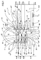
図1に図示されたラジアルターボ機械1は、遠心力を利用した単一ロータ付きラジアル型膨張タービンである。たとえば、タービン1は、有機ランキンサイクル(ORC)型の、たとえば、熱源として地熱資源を活用する発電プラント分野で使用可能である。
The
タービン1は、固定ケーシング3を備え、その中にロータが収容され、ロータ2は回転できるようになっている。このため、ロータ2は、しっかりとシャフト4に連結され、シャフト4は、(シャフト4およびロータ2の回転軸と一致する)中心軸「X−X」に沿って伸び、適した軸受5によって固定ケーシング3内で支持されている。ロータ2は、ロータディスク6を備え、ロータディスク6は、前述したシャフト4に直接連結され、前面7と反対側の後面8を有する。前面7は複数の突出した主要羽根付きリング9(ロータ型)を支持し、これらは、中心軸「X−X」と同心かつ同軸なので、ロータディスク6と共に回転する。
The
固定ケーシング3は、前壁10および後壁11を備え、前壁10は回転ディスク6の前面7の反対側に位置し、後壁11は、ロータディスク6の後面8の反対側に置かれる。前壁10は、開口を有し、その開口は、作動流体の為に軸方向入口12を定める。軸方向入口12は、中心軸「X−X」に置かれ、円形であり、同一軸「X−X」と同心である。固定ケーシング3は、作動流体の為に螺旋状通路13を更に有し、これは、ロータ2に関して周辺の径方向外部位置に置かれ、固定ケーシング3の出口(図示せず)と流体連通している。螺旋状通路13は、固定ケーシング3の周辺部分14によって区切られている。
The fixed
前壁10は、突出した複数の補助羽根付きリング(ステータ型(15)を支持し、これらは、同心であり、中心軸「X−X」と同軸になっている。補助羽根付きリング15は、前壁10の内面からケーシング3の内側に向かって、更に、ロータディスク6に向かって延び、主要羽根付きリング9とは径方向で交互になっており、作動流体の為の径方向膨張通路16を定めるが、作動流体は、軸方向入口12を通って入り、螺旋状通路13に入って、その後、前述した出口(図示せず)を通って固定ケーシング3を出るまで、ロータディスク2の周辺に向かって径方向に移動するときに膨張する。
The
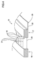
主要羽根付きリング9および補助羽根付きリング15は、それらの寸法および一部の寸法比を除いて、全て、同様の構造を有する。以下、図4を参照して、主要羽根付きリング9の構造を説明する。
The main
図4の主要羽根付きリングは、同様の寸法及び互いに軸方向に離間した根元リング17と、中心軸「X−X」と同軸の周回リング18とを備える。羽根19は、中心軸「X−X」から等距離に配置され、根元リング17および周回リング18によって、互いに接合されている。羽根19は、前記2つのリング17,18の間に延び、それらの前縁20及び後縁21は、中心軸「X−X」に対して平行または実質的に平行になっている。図示されたターボ機械1は、作動流体が径方向から外側に向かって移動する遠心力利用のラジアルタービンであることから、全ての羽根19の前縁20は径方向内側に向けられ、すなわち、中心軸「X−X」に向けられ、後縁21は、径方向外側に向けられる。
The main bladed ring of FIG. 4 includes a
主要羽根付きリング9は、連結リング22を備え、連結リング22は、根元リング17から軸方向に延び、同様に、中心軸「X−X」と同軸になっている。図4から分かるように、連結リング22は、根元リング17より非常に小さい径方向の厚さを有し、たとえば、根元リング17の厚さの約10分の1に等しい厚さを有する。連結リング22の一つの環状端23には、ロータディスク6の前面との連結の為に一種の脚部が設けられている。連結リング22の(根元リング17と比べて)減少した厚さは、連結リング22に弾性降伏、すなわち、(温度および遠心力の関数として)連結リング22がタービン1の負荷を受けるとき、その径方向の変形を可能にする。
The main
図1に図示されたタービン1は、デフレクタ24またはノーズを備え、これらは、中心軸「X−X」に沿って固定ケーシング内に置かれ、軸方向入口12に面する。デフレクタ24は、軸方向入口12付近に位置する固定ケーシング3の内壁と共に連結ダクト25を区切り、接続ダクト25は、軸方向入口12を径方向膨張通路16で接続する。デフレクタ24は、軸方向入口12に向けられた凸面を持つ隆起ディスクプロファイルを有する。
The
デフレクタ24の径方向周辺部分は、一連のステータ羽根26を担持し、一連のステータ羽根26は、中心軸「X−X」の周りに、中心軸「X−X」から等距離に配置される。前記ステータ羽根26は、固定ケーシング3の管状部分およびデフレクタ24の径方向周辺部分の間で延び、それらの前縁および後縁は、中心軸「X−X」に対して平行または実質的に平行になっている。前記ステータ羽根26は、接続用ダクト25内に置かれ、タービン1に入る流体が合う径方向膨張通路16の最初の固定羽根である。
The radial peripheral portion of the
前述したステータ羽根26に対して径方向の外部位置に置かれるのは、第1主要ロータ羽根付きリング9であり,ロータディスク6に対して径方向最内部のものである。第1主要ロータ羽根付きリング9のロータ羽根19は、デフレクタ24に固定されたステータ羽根26の位置に対応した位置にセットされ、それらは、共に、タービン1の第1段を形成する。
A
図1及び図2に見られるように、第1主要ロータ羽根付きリング9の根元リング17の径方向内面およびデフレクタ24の径方向周辺部分の径方向外面27の間で、更に、第1主要ロータ羽根付きリング9の周回リング18の径方向内面および子知恵ケーシング3の管状部分の径方向外面28の間で、第1軸方向通路29'、即ち、中心軸「X−X」に対して平行に軸方向に延びる環状容積が区切られている。第1軸方向通路29'には何もシールが設定されず、第1軸方向通路29'は、径方向膨張通路16と交差している。そのため、ステータ羽根26から離れる流体は、自由に第1軸方向通路29'を満たす。第1軸方向通路29'は、ステータ羽根26の出口圧力にある。
As can be seen in FIGS. 1 and 2, between the radial inner surface of the
凸状の面の反対側のデフレクタ24の一面は、ロータディスク6に向けられ、ロータディスク6の前面7の径方向内側部分および第1主要ロータ羽根付きリング9'で、前述した第1軸方向通路29'と流体連通している略円筒状中央前方チャンバ30を区切る。そのため、前記略円筒状中央前方チャンバ30は、同様に、ステータ羽根26の出口圧力にある。
One surface of the
第1補助ステータ羽根付きリング15'は、第1主要ロータ羽根付きリング9'に対して径方向外部位置に置かれている。第1補助ステータ羽根付きリング15'のステータ羽根19は、径方向最内部の第1主要ロータ羽根付きリング9'のロータ羽根19の位置に対応した位置にセットされている。
The ring 15'with the first auxiliary stator blade is arranged at a radial outer position with respect to the ring 9'with the first main rotor blade. The
図1および図2から分かるように、第1主要ロータ羽根津付きリング9'の根元リング17の径方向外面および第1補助ステータ羽根付きリング15'の周回リング18の径方向内面の間、さらに、第1主要ロータ羽根付きリング9'の周回リング18の径方向外面および第1補助ステータ羽根付きリング15'の根元リング17の径方向外面の間には、径方向シール31があり、これは、第1段の羽根19から離れる作動流体の通過を防止する。
As can be seen from FIGS. 1 and 2, between the radial outer surface of the
径方向シール31は、隣接した周回リング18及び根元リング17の径方向外面と協働する根元リング17及び周回リング18の径方向内面に装着された密封要素を備える。密封要素は、たとえば、それらを支持する表面から径方向に突出する環状壁であり、反対側の表面をグレージングまたは接触させる。説明された径方向シール31は、単一直径にセットされる。
The
第1主要ロータ羽根付きリング9'の末端の軸方向端部、または、より正確には、前記第1主要ロータ羽根付きリング9'の周回リング18の先端面は、固定ケーシング3の前壁10の内面から離間されている。前記先端面は、前壁10の一部分と共に、更に、第1補助ステータ羽根付きリング15'と共に、第1補助前方環状チャンバ32を区切っている。
The axial end of the first main rotor bladed ring 9'or, more precisely, the tip surface of the
第1補助スタータ羽根付きリング15'の末端軸方向端部、または、より正確には、前記第1補助ステータ羽根付きリング15'の周回リング18の先端面は、ロータディスク6の前面7から離間されている。前記先端面は、ロータディスク6の前面7の一部分、第1主要ロータ羽根付きリング9'、第2主要ロータ羽根付きリング9''と共に、第1主要前方環状チャンバ33を区切っている。ロータディスク6の前面7の前述した部分は、ロータディスク6の前方環状領域を定める。
The terminal axial end of the first auxiliary starter bladed ring 15', or more precisely, the tip surface of the
第2主要ロータ羽根付きリング9''は、第1補助ステータ羽根付きリング15'に対して径方向外部位置に置かれ、第2主要ロータ羽根付きリング9''のロータ羽根19は、第1補助ステータ羽根付きリング15'の羽根19の位置に対応した位置にセットされ、それらは、共に、タービン1の第2段を形成する。
The
図1及び図2から分かるように、第2主要ロータ羽根津付きリンツ9''の根元リング17の径方向内面および第1補助ステータ羽根付きリング15'の周回リング18の径方向外面の間で、さらに、第1ロータ羽根付きリング9'の周回リング18の径方向内面および第1補助ステータ羽根付きリング15'の根元リング17の径方向外面の間で、第2軸方向通路29''、即ち、中心軸「X−X」に対して平行な軸方向に延びる環状容積が区切られている。第1軸方向通路29''には何もシールが設定されず、第2軸方向通路29''は、径方向膨張通路16と交差している。そのため、第1補助ステータ羽根付きリング15'の羽根19から離れる流体は、自由に第2軸方向通路29''を満たす。第2軸方向通路29''は、第1補助ステータ羽根付きリング15'の羽根の出口圧力にあり、第1前方主要チャンバ33と流体連通しているので、同一圧力にある。
As can be seen from FIGS. 1 and 2, between the radial inner surface of the
第2主要ロータ羽根付きリング9''の末端の軸端部、または、より正確には、前記第2主要ロータ羽根付きリング9''の周回リング18の先端面は、固定ケーシング3の前壁10の内面から離間されている。前記先端面は、前壁10の一部分と共に、更に、第1補助ステータ羽根付きリング15'と共に、第2補助前方環状チャンバ34を区切っている。第2軸方向通路29''は、第2補助前方環状チャンバ34とも流程連通している。
The shaft end of the end of the second main rotor bladed ring 9'', or more precisely, the tip surface of the
タービン1は、第2補助ステータ羽根付きリング15''、第3主要ロータ羽根付きリング9'''、第3補助ステータ羽根付きリング15'''、第4主要ロータ羽根付きリング9''''を備える。それらの構造は、前述した構造と実質的に同一である。
The
径方向シール31は、第3主要ロータ羽根付きリング9'''および第3補助ステータ羽根付きリング15'''の間、さらに、第2主要ロータ羽根付きリング9''および第2補助ステータ羽根付きリング15''の間に設定されている。そのため、区切られているのは、第2主要前方環状チャンバ35,第3主要前方環状チャンバ36、第3補助前方環状チャンバ37、第4補助前方環状チャンバ38である。第3軸方向通路29'''は、第2主要前方環状チャンバ35を第3補助前方環状チャンバ37と連通するように置くので、両方は同一圧力である。第4軸方向通路29''''は、第3主要前方環状チャンバ36を第4補助前方環状チャンバ38と連通するように置くので、両方は同一圧力である。
The
各々の主要前方環状チャンバ33,35,36は、ロータディスク6の、それぞれの前方環状領域に対応する。実質的に円筒状中央前方チャンバ30は、ロータディスク6の前方円形領域に対応する。
Each of the main anterior
タービン1は、径方向外部密封リング39を更に備え、径方向外部密封リング39は、前壁10の内面からケーシング3の内側に向かって延び、第4主要ロータ羽根付きリング9''''の周回リング18を囲んでいる。径方向外部密封リング39は、羽根付きではないが、連結リング22によって固定ケーシング3に連結された根元リング17の構造を有する。径方向シール31は、径方向外部密封リング39および第4主要ロータ羽根付きリング9''''の周回リング18の間に入れられ、第4補助前方環状チャンバ38から螺旋状通路13への流体の直接通過を防止し、すなわち、第4主要ロータ羽根付きリング9''''の羽根19を流体が迂回することを防止する。
The
タービン1は、3つの同心の主要密封リング40'、40'',40''',40''''を更に備え、これらは、ロータディスク6の後面8に配置されている。主要密封リング40'、40'',40''',40''''は、固定ケーシング3と共に、4つの後方環状主要チャンバ41'、41'',41''',41''''を区切っている。
より具体的には、全ての主要密封リング40'、40'',40''',40''''は、径方向外部密封リング39と構造的に類似しているので、連結リング22によって固定ケーシング3に連結された根元リング17を備える。径方向シール31は、全ての主要密封リング40'、40'',40''',40''''の根元リング17及び、ロータディスク6に一体化され、中心軸「X−X」と同軸の、それぞれの環状突起42'、42'',42''',42''''の間に入れられている。
More specifically, all major sealing rings 40', 40'', 40''', 40'''' are structurally similar to the radial
第1後方環状主要チャンバ41'は、ロータディスク6の後面8の第1環状領域、固定ケーシング3の後壁11の第1環状部分、第1径方向最内部後方密封リング40'、シャフト4によって区切られる。ロータディスク6を通過する(図1には一つだけが見える)複数の第1ダクト43は、第1後方環状主要チャンバ41'を略円筒状前方チャンバ30との流体連通に置く。そのため、第1補助前方環状チャンバ32、第1軸方向通路29'、略円筒状前方チャンバ30、第1後方環状チャンバ41'は、全て、同一圧力「P1」である。
The first rear annular main chamber 41'is formed by the first annular region of the
第2後方環状主要チャンバ41''は、ロータディスク6の第2後方環状領域、第1後方密封リング40'、第2後方密封リング40''、固定ケーシング3の後壁11の第2環状部分によって区切られている。中心軸「X−X」と平行なロータディスク6を通過する(図1に一つしか見えない)複数の第2ダクトは、第2後方環状主要チャンバ41''を第1主要前方環状チャンバ33と流体流通に置く。そのため、第2補助前方環状チャンバ34、第2軸方向通路29''、第2後方環状主要チャンバ41''、第1主要前方環状チャンバ33は、全て、同一圧力「P2」である。
The second rear annular main chamber 41'' is the second rear annular region of the
第3後方環状主要チャンバ41'''は、ロータディスク6の第3後方環状領域、第2後方密封リング40''、第3後方密封リング40'''、固定ケーシング3の後壁11の第3環状部分によって区切られている。中心軸「X−X」に対して平行であるロータディスク6を通過する(図1には一つだけが見える)複数の第3ダクト45は、第3後方環状主要チャンバ41'''を第2主要環状チャンバ35との流体連通に置く。そのため、第3補助前方環状チャンバ37、第3軸方向通路29'''、第3後方環状主要チャンバ41'''、第2主要前方環状チャンバ35は、全てが同一の第3圧力「P3」である。
The third rear annular main chamber 41'''' is the third rear annular region of the
第4後方環状主要チャンバ41''''は、ロータディスク6の第4後方環状領域、第3後方密封リング40'''、第4後方密封リング40''''、固定ケーシング3の後壁11の第4環状部分によって区切られている。中心軸「X−X」に対して平行であるロータディスク6を通過する(図1には一つだけが見える)複数の第4ダクト46は、第4後方環状主要チャンバ41''''を第3主要前方環状チャンバ36と流体連通に置く。そのため、第4補助前方環状チャンバ38、第4軸方向通路29''''、第4後方環状主要チャンバ41''''、第3主要前方環状チャンバ36は、全てが同一の第4圧力「P4」である。
The fourth rear annular main chamber 41'''' is the fourth rear annular region of the
入口圧力「Pin」で軸方向入口12を通って入る作動流体は、ステータ羽根26を通過した後、第1圧力「P1」を有する。前記第1圧力「P1」は、(推力F1_=P1*A_1fを発生させ)ロータディスク6の第1前方領域「A_1f」に作用するが、これは、ロータディスク6の前方円形領域と第1主要ロータ羽根付きリング9'の周回リング18の先端面の領域との合計に等しい。
The working fluid entering through the
第1圧力「P1」は、前記ロータディスク6の第1後方環状領域「A_1p」に作用し、反対推力F_1p=P1*A_1pを発生させる。前記第1後方環状領域「A_1p」は、ロータディスク6の後面8の領域に等しく、これは、第1後方環状主要チャンバ41'に属し、シャフト4を囲んでいる。第1前方領域「A_1f」は、第1後方環状領域「A_1p」と等しいので、合成の推力はゼロになる(F1_f=F_1p)。
The first pressure "P1" acts on the first rear annular region "A_1p" of the
膨張径方向通路16に沿って続けると、作動流体は、第1主要羽根付きリング9'の羽根19および第1補助羽根付きリング15'の羽根19を通過する。第1補助羽根付きリング15'のちょうど下流側で、作動流体は、第2圧力「P2」を有する。前記第2圧力「P2」は、推力F_2f=P2*A_2fを発生させる。第2前方環状領域「A_2f」は、第2主要ロータ羽根付きリング9''の周回リング18の先端面と、第1前方主要チャンバ33内に含まれるロータディスク6の前面7の環状領域および前記ロータディスク6に向けられた第1主要ロータリング9'の根元リング17の先端面の領域の間の差との合計に等しい。
Continuing along the
同一の第2圧力「P2」は、前記ロータディスク6の第2後方環状領域「A_2p」に作用し、反対推力F_2p=P2*A_2pを発生させる。前記第2後方環状領域「A_2p」は、第2後方環状主要チャンバ41''に属するロータディスク6の後面8の領域に等しい。第2前方領域「A_2f」は、第2後方環状領域「A_2p」と等しいので、合成の推力はゼロになる(F2_f=F_2p)。
The same second pressure "P2" acts on the second rear annular region "A_2p" of the
作動流体は、第2主要羽根付きリング9''の羽根19および補助羽根付きリング15''の羽根19を通過する。第2補助羽根付きリング15''のちょうど下流側で、作動流体は第3圧力「P3」を有する。前記第3圧力「P3」は、推力F_3f=P3*A_3fを発生させる。第3前方環状領域「A_3f」は、第3主要ロータ羽根付きリング9'''の周回リング18の先端面の領域と、第2前方主要チャンバ35に含まれるロータディスク6の前面7の環状領域および前記ロータディスク6に向けられた第2主要ロータリング9''の根元リング17の先端面の領域の間の差との合計に等しい。
The working fluid passes through the
同一圧力「P3」は、前記ロータディスク6の第3後方環状領域「A_3p」に作用し、反対推力F_3p=P3*A_3pを発生させる。前記第3後方環状領域「A_3p」は、第3後方環状主要チャンバ41'''に属するロータディスク6の後面8の領域に等しい。第3前方領域「A_3f」は、第3後方環状領域「A_3p」と等しいので、合成の推力はゼロになる(F3_f=F_3p)。
The same pressure "P3" acts on the third rear annular region "A_3p" of the
作動流体は、第3主要羽根付きリング9'''の羽根19および補助羽根付きリング15'''の羽根19を通過する。補助羽根付きリング15'''のちょうど下流側で、作動流体は、第4圧力「P4」を有する。前記第4圧力「P4」は、推力F_4f=P4*A_4fを発生させる。第4前方環状領域「A_4f」は、第4主要ロータ羽根付きリング9''''の周回リング18の先端面の領域と、第3前方主要チャンバ36に含まれるロータディスク6の前面7の環状領域および前記ロータディスク6に向けられた第3主要ロータリング9'''の根元リング17の先端面の領域の差との合計に等しい。
The working fluid passes through the
同一の第4圧力「P4」は、前記ロータディスク6の第4後方環状領域「A_4p」に作用し、反対推力F_4p=P4*A_4pを発生させる。
The same fourth pressure "P4" acts on the fourth rear annular region "A_4p" of the
前記第4後方環状領域「A_4p」は、全体または部分的に、シャフト4に外側から作用する外部/大気圧P_atmの推力を釣り合わせるように設計されている。第4後方環状主要チャンバ41''''は、シャフト4に作用する外部/大気圧P_atmの軸方向推力補償の為のチャンバであり、第4後方環状領域「A_4p」は、シャフト4の補償領域である。
The fourth rear annular region "A_4p" is designed to balance the thrust of the external / atmospheric pressure P_atm acting on the
図1の実施形態において、第4主要環状チャンバ41''''および第4後方環状領域「A_4p」は、ロータディスク6の最大直径によって制限される。留意されるように、実際、ロータディスク6の周縁部は、第4主要羽根付きリング9''''で終わっている。第4後方環状領域「A_4p」は、それぞれの前方環状領域「A_4p」及び以下の関係式に従う回転シャフト4の横断面領域「A_a」の間の差に等しい。A_4p=A_4f−A_a
In the embodiment of FIG. 1, the fourth major annular chamber 41'''' and the fourth posterior annular region "A_4p" are limited by the maximum diameter of the
第1前方領域、第2前方領域、第3前方領域に作用する力は、第1後方領域、第2後方領域、第3後方領域に作用する力によって釣り合わされるのが好ましいが(F_1f=F1_p;F_2f=F_2p;F_3f=F_3p)、ロータディスク6によって形成されるロータ2に作用する合成の軸方向の力は、以下の合力と等しい。
The forces acting on the first anterior region, the second anterior region, and the third anterior region are preferably balanced by the forces acting on the first posterior region, the second posterior region, and the third posterior region (F_1f = F1_p). F_2f = F_2p; F_3f = F_3p), the combined axial force acting on the
合力=F_4f−F_4p−F_shaft= Resultant force = F_4f-F_4p-F_shaft =
(P4*A_4f)−(P4*A_4p)−Patm*A_a= (P4 * A_4f)-(P4 * A_4p) -Patm * A_a =
P4*A_4f−P4*A_4f+P4*A_a−Patm*A_a= P4 * A_4f-P4 * A_4f + P4 * A_a-Patm * A_a =
A_a*(P4−P_atm) A_a * (P4-P_atm)
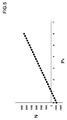
そのため、合成の軸方向の力は、シャフトの領域と、最終ステータの外部圧力「P4」及び大気圧P_atmの差との関数になる。シャフトの直径120mm、大気圧が101000Paと仮定すると、推力は、最低で、P4=0バール絶対圧(真空下)のとき、1142Nに等しく、最大圧力が考慮されるときに最大になり、これは、ORCサイクルにおいて、通常、6バール(絶対)を超えず(一般には0.5〜1.5バール(絶対))であり、5640Nに等しい(図5)。 Therefore, the combined axial force is a function of the region of the shaft and the difference between the external pressure "P4" and the atmospheric pressure P_atm of the final stator. Assuming a shaft diameter of 120 mm and an atmospheric pressure of 101000 Pa, the thrust is at least equal to 1142 N at P4 = 0 bar absolute pressure (under vacuum) and maximal when maximum pressure is taken into account. , In the ORC cycle, it usually does not exceed 6 bar (absolute) (generally 0.5-1.5 bar (absolute)) and is equal to 5640 N (FIG. 5).
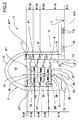
図2の変形実施形態において、第4後方環状領域「A'_4p」は、第4主要羽根付きリング9''''を越えて径方向に延び、所定の設計条件(設計点)に対して合成の軸方向の力を全体的に相殺するものである。シャフト4の補償領域「A'_4p」は、それぞれの前方環状領域および係数の合計に等しいが、係数は、シャフト4の横断面領域と外部/大気圧「P_atm」との関数である。換言すると、シャフトの補償領域は、追加領域によって増加される。前記追加領域は、第4径方向最外部後方密封リング40''''の直径、すなわち、第4径方向最外部後方環状主要チャンバ41''''の直径を増加することによって得られる。
In the modified embodiment of FIG. 2, the fourth rear annular region "A'_4p" extends radially beyond the fourth main
P_outを第4主要羽根付きリング9''''の出口圧力、すなわち、第5前方環状追加領域「A_5f」に作用する螺旋状通路13における出口圧力と呼ぶと、以下の場合に合力はゼロになる。
If P_out is called the outlet pressure of the 4th main bladed ring 9'''', that is, the outlet pressure in the
合力=F_4f+F_5f−F_4p−F_shaft=(P4*A_4f)+(P_out*A_5f)−(P4*A'_4p)−Patm*A_a=0 Resultant force = F_4f + F_5f-F_4p-F_shaft = (P4 * A_4f) + (P_out * A_5f)-(P4 * A'_4p) -Patm * A_a = 0
ここで、 here,
A'_4p=A_4p+A_5f A'_4p = A_4p + A_5f
さらに、 Moreover,
A_4p=A_4f−A_a A_4p = A_4f-A_a
P4*A_4f+P_out*A'_4p−P_out*A_4p−P4*A'_4p−Patm*A_a=0 P4 * A_4f + P_out * A'_4p-P_out * A_4p-P4 * A'_4p-Patm * A_a = 0
P4*A'4p−P_out*A'4p=P4*A_4f−P_out*A_4p−Patm*A_a P4 * A'4p-P_out * A'4p = P4 * A_4f-P_out * A_4p-Patm * A_a
A'_4p*(P4−P_out)=P4*A_4f−P_out*(A_4f−A_a)−Patm*A_a A'_4p * (P4-P_out) = P4 * A_4f-P_out * (A_4f-A_a) -Patm * A_a
A'_4p*(P4−P_out)=A_4f*(P4−P_out)+A_a*(P_out−P_atm) A'_4p * (P4-P_out) = A_4f * (P4-P_out) + A_a * (P_out-P_atm)
そのため、所定の設計条件の為の合成の軸方向の力を全体的に相殺する第4後方環状領域「A'_4p」は、 Therefore, the fourth posterior annular region "A'_4p" that totally cancels the combined axial force for the given design conditions is
A'_4p=A_4f+A_a*(Pout−P_atm)/(P4−Pout) A'_4p = A_4f + A_a * (Pout-P_atm) / (P4-Pout)
または、換言すれば、 Or, in other words
A5_f=A_a*(P4−P_atm)/(P4−Pout) A5_f = A_a * (P4-P_atm) / (P4-Pout)
設計が当該機械の高い放出圧力「P_out」(例えば15バール)を与える場合、さらに、最終ロータにおける膨張比1.2を仮定する場合(P4=1.2*P_out)、推力を排除する為に必要な領域「A5_f」は、次式になる。
To eliminate thrust if the design gives the machine a high release pressure "P_out" (
A5_f=A_a*(18−1)/(18−15)=5.66*A_a A5_f = A_a * (18-1) / (18-15) = 5.66 * A_a
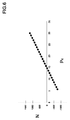
図6は、そのような領域、圧力15バール、合力の軸方向の力がゼロのものを図示する。そのような推力値は、有機膨張器で一般に使用される転がり軸受によって更に低くなり、「耐えられる」。実際、直径が120mm、大気圧が101000Paに等しく、最終ステータの設計出口圧力「P4」が15バールに等しく、最終ロータの膨張βが1.2に等しいと仮定すると、推力は、「P4」=0バール(絶対、真空下)で最低になり、−1142Nに等しく、通常は30バール(絶対)を越えない考慮されるべき最大圧力で最大になり、+1142Nに等しい。 FIG. 6 illustrates such a region, a pressure of 15 bar, and an axial force of the resultant force of zero. Such thrust values are further reduced and "bearable" by rolling bearings commonly used in organic expanders. In fact, assuming that the diameter is 120 mm, the atmospheric pressure is equal to 101000 Pa, the design outlet pressure "P4" of the final stator is equal to 15 bar, and the expansion β of the final rotor is equal to 1.2, the thrust is "P4" = It is lowest at 0 bar (absolute, under vacuum), equal to -1142N, and usually maximal at maximum pressure to be considered, not exceeding 30 bar (absolute), equal to + 1142N.
2つの解決策を比較すると、第2解決策は、当該機械の放出圧力「P_out」が高いとき(>5バール(絶対))明らかな利点を有する。 Comparing the two solutions, the second solution has a clear advantage when the discharge pressure "P_out" of the machine is high (> 5 bar (absolute)).
図示されていない変形実施形態において、後方環状補償チャンバは、異なる径方向の位置、たとえば、径方向最内部に置かれる。好ましくは、後方環状補償チャンバは、外部/大気圧に最も近い圧力のチャンバである。 In a modified embodiment (not shown), the posterior annular compensating chamber is placed in a different radial position, eg, the innermost radial. Preferably, the rear annular compensation chamber is the chamber with the pressure closest to the external / atmospheric pressure.
図示されてない変形実施形態において、それぞれの作動流体用軸方向通路は、径方向に隣接する段の間で区切られ、径方向シールは、同一の段の各々の主要羽根付きリングおよび補助羽根付きリングの間に入れられている。 In a modified embodiment not shown, each working fluid axial passage is separated between radially adjacent steps and the radial seal is provided with each major winged ring and auxiliary wing on the same step. It is placed between the rings.
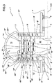
図3は、更なる実施形態を図示する。図3の実施形態は、タービン1が二重反転型であることから、図1および図2の実施形態とは異なる。タービン1は、第1ロータ2'および第2ロータ2''を備える。第1ロータ2'は、第1ロータディスク6'および第1ロータディスク6'と一体の第1回転シャフト4'を備え、中心軸「X−X」の周りを固定ケーシング3内で回転可能である。第1ロータディスク6'は、前面7'で、主要同心羽根付きリング9',9'',9''',9''''を担持する。
FIG. 3 illustrates a further embodiment. The embodiment of FIG. 3 is different from the embodiment of FIGS. 1 and 2 because the
第2ロータ2''は、第2ロータディスク6''および第2ロータディスク6''と一体の第2回転シャフト4''を備え、第1ロータディスク6'に対して反対方向に、中心軸「X−X」の周りを固定ケーシング3内で回転可能である。
The
第2ロータディスク6''は、前面7''で、同心の補助羽根付きリング15',15'',15'''を担持し、これらは、同様に羽根付きロータリングである。特に、第1主要羽根付きリング9'は、径方向最内部位置に設定され、中心軸から径方向に離れるが、第1補助羽根付きリング15'、第2主要羽根付きリング9''、第2補助羽根付きリング15''、第3主要羽根付きリング9'''、第3補助羽根付きリング15''、第4主要羽根付きリング9''''が追従する。径方向外部密封リング39は、第2ロータディスク6''の前面7''から延び、第4主要羽根付きリング9''''の周回リング18を囲む。
The
略円筒状前方チャンバ30,環状前方主要チャンバ33,35,36,後方環状主要チャンバ41',41'',41''',41''''、第2補助通路29''、第3補助通路29'''、第4補助通路29''''、第2補助前方環状チャンバ34,第3補助前方環状チャンバ37,第4補助前方環状チャンバ38の構造は、図1及び図2のタービンの為に説明されたものと実質的に同一である。
Approximately cylindrical
それらのタービンと異なり、図3のタービンは、第1軸方向通路29'を持たず、第1補助前方環状チャンバ32を持たない(他の3つの補助前方環状チャンバのみを有する)。 Unlike those turbines, the turbine of FIG. 3 does not have a first axial passage 29'and does not have a first auxiliary anterior annular chamber 32 (has only the other three auxiliary anterior annular chambers).
さらに、第2ロータディスク6''は、第1ロータディスク6'と同一の原理に従って、補助的に釣り合わされている。図3のタービン1は、実際、補助推力を釣り合わせる為に補助後方チャンバ47',47'',47''',47''''を有する。固定ケーシング3と一体の同心補助密封リング48,48,48,48と、第2ロータディスク6''と一体の補助環状突起49',49''、49''',49''''とは、前記補助後方チャンバ47',47'',47''',47''''を区切り、これらは、第2ロータディスク6''内に形成された、それぞれのダクト50,51,52,53を通して、それぞれの補助前方環状チャンバ34,37,38と連通している。
Further, the
他の図示しない変形実施形態において、ラジアルターボ機械は、求心力を利用するものでもよく、さらに/または、圧縮機でもよく、さらに/または蒸気で作動するように設計されてもよい。 In other modified embodiments (not shown), the radial turbomachinery may utilize centripetal force and / or may be a compressor and / or may be designed to operate on steam.
Claims (13)
固定ケーシング(3)と、
中心軸(X−X)の周りで前記固定ケーシング(3)内に配置された複数の同心の主要羽根付きリング(9',9'',9''',9'''')と、
前記中心軸(X−X)の周りで前記固定ケーシング(3)内に配置された複数の同心の補助羽根付きリング(15',15'',15''')と、
を備え、
前記補助羽根付きリング(15',15'',15''')は、前記主要羽根付きリング(9',9'',9''',9'''')と径方向で交互にされ、
前記主要羽根付きリング(9',9'',9''',9'''')の羽根(19)および前記補助羽根付きリング(15',15'',15''')の羽根(19)は、作動流体の為に径方向通路(16)を区切り、
ロータディスク(6,6')および前記ロータディスク(6,6')と一体の回転シャフト(4,4',4'')を備える少なくとも一つのロータ(2,2')は、前記固定ケーシング(3)内で前記中心軸(X−X)の周りを回転可能であり、前面(7,7)で、前記主要羽根付きリング(9',9'',9''',9'''')を担持し、
前記主要羽根付きリング(9',9'',9''',9'''')および補助羽根付きリング(15',15'',15''')は、異なる圧力において、複数の同心の前方主要チャンバ(30,33,35,36)をロータディスク(6,6')で区切り、
前記同心の前方主要チャンバ(30,33,35,36)は、前記ロータディスク(6,6’)の前方領域(A_1f,A_2f,A_3f)によって区切られ、
複数の同心後方環状主要チャンバ(41',41'',41''',41'''')は、各々が、前記前方主要チャンバ(30,33,35,36)と同一圧力で、それぞれの前方主要チャンバ(30,33,35,36)と流体連通するが、前記ロータディスク(6,6')の後面(8,8')および前記固定ケーシング(3)の間で区切られ、
前記同心の後方環状主要チャンバ(41',41'',41''',41'''')は、前記ロータディスク(6,6’)の後方環状領域(A_1p,A_2p,A_3p,A_4p;A’_4p)によって区切られ、
前記後方環状領域(A_1p,A_2p,A_3p,A_4p;A’_4p)の全てが、補償領域(A_4p,A'_4p)と呼ばれる一つの前方領域を除いて、それぞれの前方領域(A_1f,A_2f,A_3f)と同一であり、前記補償領域(A_4p,A'_4p)は、前記シャフトに作用する外部圧力の推力を少なくとも部分的に補償するように構成されている、ターボ機械。 A radial turbomachine with axial thrust compensation
Fixed casing (3) and
A plurality of concentric main bladed rings (9', 9'', 9''', 9'''') arranged in the fixed casing (3) around the central axis (XX).
A plurality of concentric rings with auxiliary blades (15', 15'', 15''') arranged in the fixed casing (3) around the central axis (XX).
With
The ring with auxiliary blades (15', 15'', 15''') alternates with the ring with main blades (9', 9'', 9''', 9'''' in the radial direction. Being done
The blades (19) of the ring with main blades (9', 9 ", 9"",9"") and the blades of the ring with auxiliary blades (15', 15", 15 ""). (19) separates the radial passage (16) for the working fluid.
At least one rotor (2,2') comprising a rotor disk (6,6') and a rotating shaft (4,4', 4'') integrated with the rotor disk (6,6') is the fixed casing. It is rotatable around the central axis (XX) within (3), and at the front surface (7,7), the ring with main blades (9', 9'', 9''', 9'''') Carrying
The main bladed ring (9', 9'', 9''', 9'''') and the auxiliary bladed ring (15', 15'', 15''') have a plurality of rings at different pressures. Concentric front major chambers (30, 33, 35, 36) separated by rotor disks (6,6')
The concentric anterior main chambers (30, 33, 35, 36) are separated by anterior regions (A_1f, A_2f, A_3f) of the rotor disk (6,6').
The plurality of concentric posterior annular main chambers (41', 41'', 41''', 41'''') each have the same pressure as the anterior main chambers (30, 33, 35, 36), respectively. Fluid communication with the front main chambers (30, 33, 35, 36), but separated between the rear surface (8, 8') of the rotor disk (6, 6') and the fixed casing (3).
The concentric posterior annular main chambers (41', 41'', 41''', 41'''') are located in the posterior annular region (A_1p, A_2p, A_3p, A_4p) of the rotor disk (6,6'); Separated by A'_4p)
All of the posterior annular regions (A_1p, A_2p, A_3p, A_4p; A'_4p) are the respective anterior regions (A_1f, A_2f, A_3f) except for one anterior region called the compensation region (A_4p, A'_4p). ) and identical, the compensation area (A_4p, A'_4p) is the thrust of the external pressure acting on the shaft that is configured to at least partially compensate, the turbomachine.
A'_4p=A_4f+A_a*(Pout−Patm)/(P4−Pout)
に等しい、請求項8に記載のターボ機械。 In order to completely offset the axial force of the composition, the compensation region is
A'_4p = A_4f + A_a * (Pout-Patm) / (P4-Pout)
The turbomachinery according to claim 8, which is equal to.
Applications Claiming Priority (3)
| Application Number | Priority Date | Filing Date | Title |
|---|---|---|---|
| ITUA2016A002125A ITUA20162125A1 (en) | 2016-03-30 | 2016-03-30 | Radial turbomachinery with axial thrust compensation |
| IT102016000032690 | 2016-03-30 | ||
| PCT/IB2017/051783 WO2017168334A1 (en) | 2016-03-30 | 2017-03-29 | Radial turbomachine with axial thrust compensation |
Publications (2)
| Publication Number | Publication Date |
|---|---|
| JP2019513200A JP2019513200A (en) | 2019-05-23 |
| JP6957833B2 true JP6957833B2 (en) | 2021-11-02 |
Family
ID=56413737
Family Applications (1)
| Application Number | Title | Priority Date | Filing Date |
|---|---|---|---|
| JP2018550839A Active JP6957833B2 (en) | 2016-03-30 | 2017-03-29 | Radial turbomachinery with axial thrust compensation |
Country Status (8)
| Country | Link |
|---|---|
| US (1) | US10934843B2 (en) |
| EP (1) | EP3436666B1 (en) |
| JP (1) | JP6957833B2 (en) |
| ES (1) | ES2794789T3 (en) |
| HR (1) | HRP20200742T8 (en) |
| IT (1) | ITUA20162125A1 (en) |
| PT (1) | PT3436666T (en) |
| WO (1) | WO2017168334A1 (en) |
Families Citing this family (6)
| Publication number | Priority date | Publication date | Assignee | Title |
|---|---|---|---|---|
| FR3096734B1 (en) * | 2019-05-29 | 2021-12-31 | Safran Aircraft Engines | Turbomachine kit |
| CN113153455B (en) * | 2020-12-01 | 2023-03-21 | 中国船舶重工集团公司第七0三研究所 | Radial flow turbine axial force self-adaptive control method |
| CN112627913B (en) * | 2020-12-01 | 2022-08-19 | 中国船舶重工集团公司第七0三研究所 | Radial flow turbine axial force self-adaptive control system |
| CN115355193B (en) * | 2022-10-24 | 2023-03-07 | 中国航发四川燃气涡轮研究院 | Dynamic regulation and control method for axial force of gas compressor under heating and pressurizing conditions |
| CN116044579B (en) * | 2022-12-01 | 2026-02-27 | 中国船舶重工集团公司第七0三研究所 | A method for dynamically adjusting the axial force of a marine gas turbine rotor |
| CN119801661B (en) * | 2025-01-14 | 2025-10-28 | 上海交通大学 | Supercritical CO2 axial flow turbine unit and axial force measurement and regulation method thereof |
Family Cites Families (9)
| Publication number | Priority date | Publication date | Assignee | Title |
|---|---|---|---|---|
| FR376214A (en) * | 1906-04-04 | 1907-08-03 | Birger Ljungstroem | Device for balancing the axial pressure on the vanes of radial turbines |
| US997629A (en) | 1911-03-20 | 1911-07-11 | Ljungstroems Angturbin Ab | Labyrinth-packing for turbines. |
| US2102637A (en) * | 1932-06-01 | 1937-12-21 | Mcininghaus Ulrich | Arrangement of radially traversed blades in rotary machines |
| US2374671A (en) * | 1941-06-24 | 1945-05-01 | Dupont Emile | Turbine |
| US2626501A (en) * | 1944-10-07 | 1953-01-27 | Turbolectric Corp | Gas turbine power plant having compressor, turbine, and hollow shaft therebetween |
| JP2006144758A (en) * | 2004-11-25 | 2006-06-08 | Jfe Engineering Kk | Radial flow steam turbine |
| CA2943407A1 (en) * | 2014-03-21 | 2015-09-24 | Exergy S.P.A. | Centrifugal radial turbine |
| US10876406B2 (en) * | 2014-03-21 | 2020-12-29 | Exergy S.P.A. | Radial turbomachine |
| MX2016014513A (en) * | 2014-05-05 | 2017-05-23 | Exergy Spa | Radial turbomachine. |
-
2016
- 2016-03-30 IT ITUA2016A002125A patent/ITUA20162125A1/en unknown
-
2017
- 2017-03-29 EP EP17722154.6A patent/EP3436666B1/en active Active
- 2017-03-29 HR HRP20200742TT patent/HRP20200742T8/en unknown
- 2017-03-29 WO PCT/IB2017/051783 patent/WO2017168334A1/en not_active Ceased
- 2017-03-29 PT PT177221546T patent/PT3436666T/en unknown
- 2017-03-29 ES ES17722154T patent/ES2794789T3/en active Active
- 2017-03-29 US US16/090,420 patent/US10934843B2/en active Active
- 2017-03-29 JP JP2018550839A patent/JP6957833B2/en active Active
Also Published As
| Publication number | Publication date |
|---|---|
| ES2794789T3 (en) | 2020-11-19 |
| US20190120056A1 (en) | 2019-04-25 |
| HRP20200742T8 (en) | 2020-08-21 |
| ITUA20162125A1 (en) | 2017-09-30 |
| EP3436666A1 (en) | 2019-02-06 |
| PT3436666T (en) | 2020-05-19 |
| US10934843B2 (en) | 2021-03-02 |
| WO2017168334A1 (en) | 2017-10-05 |
| JP2019513200A (en) | 2019-05-23 |
| EP3436666B1 (en) | 2020-02-12 |
| HRP20200742T1 (en) | 2020-07-24 |
Similar Documents
| Publication | Publication Date | Title |
|---|---|---|
| JP2019513200A (en) | Radial turbomachinery with axial thrust compensation | |
| US7824152B2 (en) | Multivane segment mounting arrangement for a gas turbine | |
| US10107126B2 (en) | Non-contact seal assembly for rotational equipment | |
| US10161251B2 (en) | Turbomachine rotors with thermal regulation | |
| JPH0580574B2 (en) | ||
| JP2015187442A (en) | Individually compliant segments for split ring hydrodynamic face seal | |
| CN107429567A (en) | It is preferred for the multi-stage turbine of organic Rankine bottoming cycle (ORC) equipment | |
| JP2011140945A (en) | Steam turbine stationary component seal | |
| JP2014521861A (en) | Centrifugal impeller and turbomachine | |
| JP7407544B2 (en) | Radially displaceable brush seal | |
| BR112017012593B1 (en) | AIRCRAFT TURBOMACHINE TURBINE SET | |
| US10876406B2 (en) | Radial turbomachine | |
| US11092028B2 (en) | Tip balance slits for turbines | |
| CN111322119B (en) | Turbine engine with floating shroud | |
| CN108374721B (en) | Rotor thrust balanced turbine engine | |
| CN109844265B (en) | Multistage axial turbines suitable for operation at low steam temperatures | |
| CN101131092B (en) | Methods and apparatus for fabricating a rotor for a steam turbine | |
| US7390160B2 (en) | Axial flow steam turbine assembly | |
| JP6955086B2 (en) | Peripheral seal configuration | |
| US7387486B2 (en) | Axial flow steam turbine assembly | |
| US3051436A (en) | Rotor for axial-flow fluid machine | |
| US11598265B2 (en) | Tangential on-board injector | |
| GB2594145A (en) | Single wheel multi-stage radially-layered regenerative pump | |
| US3724969A (en) | Turbine construction | |
| JPH10317903A (en) | Gas turbine bearing thrust force balance structure |
Legal Events
| Date | Code | Title | Description |
|---|---|---|---|
| RD04 | Notification of resignation of power of attorney |
Free format text: JAPANESE INTERMEDIATE CODE: A7424 Effective date: 20190918 |
|
| A621 | Written request for application examination |
Free format text: JAPANESE INTERMEDIATE CODE: A621 Effective date: 20200326 |
|
| A711 | Notification of change in applicant |
Free format text: JAPANESE INTERMEDIATE CODE: A711 Effective date: 20200605 |
|
| A977 | Report on retrieval |
Free format text: JAPANESE INTERMEDIATE CODE: A971007 Effective date: 20210216 |
|
| A131 | Notification of reasons for refusal |
Free format text: JAPANESE INTERMEDIATE CODE: A131 Effective date: 20210224 |
|
| A521 | Request for written amendment filed |
Free format text: JAPANESE INTERMEDIATE CODE: A523 Effective date: 20210426 |
|
| TRDD | Decision of grant or rejection written | ||
| A01 | Written decision to grant a patent or to grant a registration (utility model) |
Free format text: JAPANESE INTERMEDIATE CODE: A01 Effective date: 20210907 |
|
| A61 | First payment of annual fees (during grant procedure) |
Free format text: JAPANESE INTERMEDIATE CODE: A61 Effective date: 20210917 |
|
| R150 | Certificate of patent or registration of utility model |
Ref document number: 6957833 Country of ref document: JP Free format text: JAPANESE INTERMEDIATE CODE: R150 |
|
| R250 | Receipt of annual fees |
Free format text: JAPANESE INTERMEDIATE CODE: R250 |
|
| R250 | Receipt of annual fees |
Free format text: JAPANESE INTERMEDIATE CODE: R250 |