JP6982010B2 - Easy-open peeling pouch - Google Patents
Easy-open peeling pouch Download PDFInfo
- Publication number
- JP6982010B2 JP6982010B2 JP2018564846A JP2018564846A JP6982010B2 JP 6982010 B2 JP6982010 B2 JP 6982010B2 JP 2018564846 A JP2018564846 A JP 2018564846A JP 2018564846 A JP2018564846 A JP 2018564846A JP 6982010 B2 JP6982010 B2 JP 6982010B2
- Authority
- JP
- Japan
- Prior art keywords
- layer
- tab
- package
- notch
- zone
- Prior art date
- Legal status (The legal status is an assumption and is not a legal conclusion. Google has not performed a legal analysis and makes no representation as to the accuracy of the status listed.)
- Expired - Fee Related
Links
Images











Classifications
-
- B—PERFORMING OPERATIONS; TRANSPORTING
- B65—CONVEYING; PACKING; STORING; HANDLING THIN OR FILAMENTARY MATERIAL
- B65D—CONTAINERS FOR STORAGE OR TRANSPORT OF ARTICLES OR MATERIALS, e.g. BAGS, BARRELS, BOTTLES, BOXES, CANS, CARTONS, CRATES, DRUMS, JARS, TANKS, HOPPERS, FORWARDING CONTAINERS; ACCESSORIES, CLOSURES, OR FITTINGS THEREFOR; PACKAGING ELEMENTS; PACKAGES
- B65D75/00—Packages comprising articles or materials partially or wholly enclosed in strips, sheets, blanks, tubes or webs of flexible sheet material, e.g. in folded wrappers
- B65D75/52—Details
- B65D75/58—Opening or contents-removing devices added or incorporated during package manufacture
- B65D75/5855—Peelable seals
-
- B—PERFORMING OPERATIONS; TRANSPORTING
- B65—CONVEYING; PACKING; STORING; HANDLING THIN OR FILAMENTARY MATERIAL
- B65B—MACHINES, APPARATUS OR DEVICES FOR, OR METHODS OF, PACKAGING ARTICLES OR MATERIALS; UNPACKING
- B65B61/00—Auxiliary devices, not otherwise provided for, for operating on sheets, blanks, webs, binding material, containers or packages
- B65B61/007—Perforating strips of completed packages
-
- B—PERFORMING OPERATIONS; TRANSPORTING
- B65—CONVEYING; PACKING; STORING; HANDLING THIN OR FILAMENTARY MATERIAL
- B65B—MACHINES, APPARATUS OR DEVICES FOR, OR METHODS OF, PACKAGING ARTICLES OR MATERIALS; UNPACKING
- B65B61/00—Auxiliary devices, not otherwise provided for, for operating on sheets, blanks, webs, binding material, containers or packages
- B65B61/04—Auxiliary devices, not otherwise provided for, for operating on sheets, blanks, webs, binding material, containers or packages for severing webs, or for separating joined packages
- B65B61/06—Auxiliary devices, not otherwise provided for, for operating on sheets, blanks, webs, binding material, containers or packages for severing webs, or for separating joined packages by cutting
-
- B—PERFORMING OPERATIONS; TRANSPORTING
- B65—CONVEYING; PACKING; STORING; HANDLING THIN OR FILAMENTARY MATERIAL
- B65B—MACHINES, APPARATUS OR DEVICES FOR, OR METHODS OF, PACKAGING ARTICLES OR MATERIALS; UNPACKING
- B65B7/00—Closing containers or receptacles after filling
- B65B7/02—Closing containers or receptacles deformed by, or taking-up shape, of, contents, e.g. bags, sacks
-
- B—PERFORMING OPERATIONS; TRANSPORTING
- B65—CONVEYING; PACKING; STORING; HANDLING THIN OR FILAMENTARY MATERIAL
- B65B—MACHINES, APPARATUS OR DEVICES FOR, OR METHODS OF, PACKAGING ARTICLES OR MATERIALS; UNPACKING
- B65B9/00—Enclosing successive articles, or quantities of material, e.g. liquids or semiliquids, in flat, folded, or tubular webs of flexible sheet material; Subdividing filled flexible tubes to form packages
-
- B—PERFORMING OPERATIONS; TRANSPORTING
- B65—CONVEYING; PACKING; STORING; HANDLING THIN OR FILAMENTARY MATERIAL
- B65B—MACHINES, APPARATUS OR DEVICES FOR, OR METHODS OF, PACKAGING ARTICLES OR MATERIALS; UNPACKING
- B65B9/00—Enclosing successive articles, or quantities of material, e.g. liquids or semiliquids, in flat, folded, or tubular webs of flexible sheet material; Subdividing filled flexible tubes to form packages
- B65B9/02—Enclosing successive articles, or quantities of material between opposed webs
-
- B—PERFORMING OPERATIONS; TRANSPORTING
- B65—CONVEYING; PACKING; STORING; HANDLING THIN OR FILAMENTARY MATERIAL
- B65D—CONTAINERS FOR STORAGE OR TRANSPORT OF ARTICLES OR MATERIALS, e.g. BAGS, BARRELS, BOTTLES, BOXES, CANS, CARTONS, CRATES, DRUMS, JARS, TANKS, HOPPERS, FORWARDING CONTAINERS; ACCESSORIES, CLOSURES, OR FITTINGS THEREFOR; PACKAGING ELEMENTS; PACKAGES
- B65D75/00—Packages comprising articles or materials partially or wholly enclosed in strips, sheets, blanks, tubes or webs of flexible sheet material, e.g. in folded wrappers
- B65D75/28—Articles or materials wholly enclosed in composite wrappers, i.e. wrappers formed by associating or interconnecting two or more sheets or blanks
- B65D75/30—Articles or materials enclosed between two opposed sheets or blanks having their margins united, e.g. by pressure-sensitive adhesive, crimping, heat-sealing, or welding
-
- B—PERFORMING OPERATIONS; TRANSPORTING
- B65—CONVEYING; PACKING; STORING; HANDLING THIN OR FILAMENTARY MATERIAL
- B65D—CONTAINERS FOR STORAGE OR TRANSPORT OF ARTICLES OR MATERIALS, e.g. BAGS, BARRELS, BOTTLES, BOXES, CANS, CARTONS, CRATES, DRUMS, JARS, TANKS, HOPPERS, FORWARDING CONTAINERS; ACCESSORIES, CLOSURES, OR FITTINGS THEREFOR; PACKAGING ELEMENTS; PACKAGES
- B65D75/00—Packages comprising articles or materials partially or wholly enclosed in strips, sheets, blanks, tubes or webs of flexible sheet material, e.g. in folded wrappers
- B65D75/40—Packages formed by enclosing successive articles, or increments of material, in webs, e.g. folded or tubular webs, or by subdividing tubes filled with liquid, semi-liquid, or plastic materials
- B65D75/44—Individual packages cut from webs or tubes
- B65D75/48—Individual packages cut from webs or tubes containing liquids, semiliquids, or pastes, e.g. cushion-shaped packages
- B65D75/50—Tetrahedral packages
-
- B—PERFORMING OPERATIONS; TRANSPORTING
- B65—CONVEYING; PACKING; STORING; HANDLING THIN OR FILAMENTARY MATERIAL
- B65D—CONTAINERS FOR STORAGE OR TRANSPORT OF ARTICLES OR MATERIALS, e.g. BAGS, BARRELS, BOTTLES, BOXES, CANS, CARTONS, CRATES, DRUMS, JARS, TANKS, HOPPERS, FORWARDING CONTAINERS; ACCESSORIES, CLOSURES, OR FITTINGS THEREFOR; PACKAGING ELEMENTS; PACKAGES
- B65D75/00—Packages comprising articles or materials partially or wholly enclosed in strips, sheets, blanks, tubes or webs of flexible sheet material, e.g. in folded wrappers
- B65D75/52—Details
-
- B—PERFORMING OPERATIONS; TRANSPORTING
- B65—CONVEYING; PACKING; STORING; HANDLING THIN OR FILAMENTARY MATERIAL
- B65D—CONTAINERS FOR STORAGE OR TRANSPORT OF ARTICLES OR MATERIALS, e.g. BAGS, BARRELS, BOTTLES, BOXES, CANS, CARTONS, CRATES, DRUMS, JARS, TANKS, HOPPERS, FORWARDING CONTAINERS; ACCESSORIES, CLOSURES, OR FITTINGS THEREFOR; PACKAGING ELEMENTS; PACKAGES
- B65D75/00—Packages comprising articles or materials partially or wholly enclosed in strips, sheets, blanks, tubes or webs of flexible sheet material, e.g. in folded wrappers
- B65D75/52—Details
- B65D75/58—Opening or contents-removing devices added or incorporated during package manufacture
- B65D75/5805—Opening or contents-removing devices added or incorporated during package manufacture for tearing a side strip parallel and next to the edge, e.g. by means of a line of weakness
-
- B—PERFORMING OPERATIONS; TRANSPORTING
- B65—CONVEYING; PACKING; STORING; HANDLING THIN OR FILAMENTARY MATERIAL
- B65D—CONTAINERS FOR STORAGE OR TRANSPORT OF ARTICLES OR MATERIALS, e.g. BAGS, BARRELS, BOTTLES, BOXES, CANS, CARTONS, CRATES, DRUMS, JARS, TANKS, HOPPERS, FORWARDING CONTAINERS; ACCESSORIES, CLOSURES, OR FITTINGS THEREFOR; PACKAGING ELEMENTS; PACKAGES
- B65D75/00—Packages comprising articles or materials partially or wholly enclosed in strips, sheets, blanks, tubes or webs of flexible sheet material, e.g. in folded wrappers
- B65D75/52—Details
- B65D75/58—Opening or contents-removing devices added or incorporated during package manufacture
- B65D75/5827—Tear-lines provided in a wall portion
Landscapes
- Engineering & Computer Science (AREA)
- Mechanical Engineering (AREA)
- Chemical & Material Sciences (AREA)
- Composite Materials (AREA)
- Packages (AREA)
- Bag Frames (AREA)
Description
本願は、全ての国を指定国とする出願人である米国国内企業The Tapemark Companyの名において2017年6月8日にPCT国際特許出願として出願されており、2016年6月9日に出願された米国仮特許出願第62/348062号明細書および2017年6月7日に出願された米国特許出願第15/616666号明細書に対する優先権を主張するものであり、これら両出願の内容は、引用したことによりその全体が本明細書に組み込まれる。 This application was filed as a PCT international patent application on June 8, 2017 in the name of The Tapemark Company, a US domestic company that is the applicant with all countries designated, and was filed on June 9, 2016. It claims priority to U.S. Provisional Patent Application No. 62/348062 and U.S. Patent Application No. 15/6166666 filed June 7, 2017. The whole is incorporated herein by reference.
技術分野
本明細書に記載された技術は、パウチ領域を有するパッケージに関する。より具体的には、本明細書に記載された技術は、パウチ領域へアクセスするために層が剥離されるパッケージに関する。
Technical Fields The techniques described herein relate to packages with pouch areas. More specifically, the techniques described herein relate to packages from which layers are stripped to access the pouch area.
背景
多くの異なるタイプのパッケージは、材料の2つ以上の層から形成されており、これらの層は、製品を収容するためのパウチを形成するように互いにシールされ、次いで、製品へアクセスするために剥離させることができる。幾つかの技術分野において、最終的な使用のために無菌である製品へアクセスすることが望ましい。これは、医療分野における一般的な問題であり、例えば、医療分野では、医療行為において使用される製品は、製造施設や医療施設等において貯蔵されている間に加え、これらの施設への、また、これらの施設からの輸送中に無菌のまま保たれることが望ましい。幾つかのパッケージ設計では、層を掴み、層を剥離させるために、パッケージの層を分離させることが困難である。静電気が層を分離させにくくする働きをすることもある。外側パッケージ周縁部を切断するための切断プロセスが、外側周縁部において層をある程度融着させることがあり、これは、層を分離させにくくする可能性がある。
Background Many different types of packages are made up of two or more layers of material, which are sealed together to form a pouch for accommodating the product and then for access to the product. Can be peeled off. In some technical areas it is desirable to have access to products that are sterile for end use. This is a common problem in the medical field, for example, in the medical field, products used in medical practice are stored in manufacturing facilities, medical facilities, etc., and also to these facilities. It is desirable to remain sterile during transportation from these facilities. In some package designs, it is difficult to separate the layers of the package in order to grab the layer and peel it off. Static electricity can also make it difficult to separate layers. The cutting process for cutting the outer peripheral edge may fuse the layers to some extent at the outer edge, which can make it difficult to separate the layers.
幾つかのパッケージは、切れ目または裂け目が形成されている。この切れ目または裂け目は、製品を収容したパウチ領域の少なくとも一部へアクセスするために、使用者が、切れ目を始点としてパッケージの全ての層を裂断させることを可能にする。しかしながら、パウチ領域を横切って全ての層を裂断させることは、脆い内容物に損傷を与える可能性がある。また、パウチ領域の一方の側を横切って全ての層を裂断させることは、さらに、幾つかの状況において内容物を取り出すことを困難にする可能性がある。 Some packages have cuts or crevices formed. This cut or rift allows the user to tear all layers of the package starting from the crevice in order to access at least a portion of the pouch area containing the product. However, tearing all layers across the pouch area can damage brittle contents. Also, tearing all layers across one side of the pouch region can further make it difficult to remove the contents in some situations.
パッケージが、開封するために薄い層の手作業による分離を必要とする場合、特に、使用者の手の器用さが制限されているとき、使用者に障がいがあるとき、使用者が手袋をはめているとき、または使用者が緊急の医療必要性に対応しているとき、時間およびフラストレーションが問題となる。 The user wears gloves when the package requires a thin layer of manual separation to open, especially when the dexterity of the user's hands is limited or when the user has a disability. Time and frustration become an issue when the user is responding to an urgent medical need.
概要
本明細書に開示された実施の形態は、製品を収容および提供するためのパッケージを含む。パッケージは、第1の層と、第2の層と、剥離可能シールによって第1の層が第2の層に接合されている製品シールゾーンであって、製品を収容するためのシールされていないパウチ領域を画定する内側周縁部と、外側周縁部とを有する、製品シールゾーンと、製品シールゾーンの外側周縁部に隣接したヘッダゾーンと、を含む。ヘッダゾーンは、第1のタブと、第2のタブと、ヘッダゾーンのシールされていない部分内の第1の層における第1のタブ切込みと、ヘッダゾーンのシールされていない部分内の第2の層における第2のタブ切込みと、を含む。幾つかの実施の形態において、第1のタブ切込みは、第2のタブ切込みと交差していない。
Summary The embodiments disclosed herein include a package for accommodating and delivering a product. The package is a product seal zone where the first layer, the second layer, and the first layer are joined to the second layer by a peelable seal, and is not sealed to accommodate the product. Includes a product seal zone having an inner peripheral edge and an outer peripheral edge defining a pouch area, and a header zone adjacent to the outer peripheral edge of the product seal zone. The header zone consists of a first tab, a second tab, a first tab notch in the first layer within the unsealed portion of the header zone, and a second within the unsealed portion of the header zone. Includes a second tab notch in the layer of. In some embodiments, the first tab notch does not intersect the second tab notch.
幾つかの実施の形態において、第1のタブは、第1の層が第2の層に接合されている第1のタブシールゾーンを備え、第2のタブは、第1の層が第2の層に接合されている第2のタブシールゾーンを備える。 In some embodiments, the first tab comprises a first tab seal zone in which the first layer is joined to the second layer, the second tab having the first layer second. It comprises a second tab seal zone joined to the layer of.
幾つかの実施の形態において、第1のタブ切込みは、製品シールゾーンと第1のタブシールゾーンとの間に配置されており、第2のタブ切込みは、製品シールゾーンと第2のタブシールゾーンとの間に配置されている。 In some embodiments, the first tab notch is located between the product seal zone and the first tab seal zone, and the second tab notch is the product seal zone and the second tab seal. It is located between the zones.
幾つかの実施の形態において、第1のタブ切込みは、第1の層の一部を第1の層の残りから分離しており、第2のタブ切込みは、第2の層の一部を第2の層の残りから分離している。 In some embodiments, the first tab notch separates part of the first layer from the rest of the first layer, and the second tab notch separates part of the second layer. Separated from the rest of the second layer.
幾つかの実施の形態において、パッケージは、第1のタブと第2のタブとの間に隙間を画定している。 In some embodiments, the package defines a gap between the first tab and the second tab.
幾つかの実施の形態において、第1のタブ切込みは、隙間からパッケージの周縁部まで延びており、第2のタブ切込みは、隙間からパッケージの周縁部まで延びている。 In some embodiments, the first tab notch extends from the gap to the periphery of the package and the second tab notch extends from the gap to the periphery of the package.
幾つかの実施の形態において、第1のタブ切込みは、パッケージの第1の側部エッジまで延びており、第2のタブ切込みは、第1の側部エッジと反対側のパッケージの第2の側部エッジまで延びている。 In some embodiments, the first tab notch extends to the first side edge of the package and the second tab notch extends to the second side edge of the package opposite the first side edge. It extends to the side edge.
幾つかの実施の形態において、パッケージの外側周縁部は、第1のタブと第2のタブとの間に隙間を画定するために製品シールゾーンに向かって内方へ延びる1つのエッジに沿った外側周縁部の一部を除き、実質的に矩形である。 In some embodiments, the outer peripheral edge of the package is along one edge extending inward towards the product seal zone to define a gap between the first tab and the second tab. It is substantially rectangular except for a part of the outer peripheral edge.
幾つかの実施の形態において、隙間は、パッケージのエッジの中央から内方へ延びている。 In some embodiments, the gap extends inward from the center of the edge of the package.
幾つかの実施の形態において、第1のタブは、第1の触覚特徴部を有し、第2のタブは、第2の触覚特徴部を有する。 In some embodiments, the first tab has a first tactile feature and the second tab has a second tactile feature.
幾つかの実施の形態において、各触覚特徴部は、開口、1つまたは複数のスリット、溝、突出部および凹所から成る群から選択されている。 In some embodiments, each tactile feature is selected from the group consisting of openings, one or more slits, grooves, protrusions and recesses.
幾つかの実施の形態において、各触覚特徴部は、開口を画定しており、さらに、開口エッジの一部に沿って鈍化エレメントを備え、鈍化エレメントは、第1または第2の層のうちの少なくとも一方の折り曲げられた部分を含む。 In some embodiments, each tactile feature defines an opening and further comprises a blunting element along a portion of the opening edge, wherein the blunting element is of a first or second layer. Includes at least one bent portion.
幾つかの実施の形態において、第1の触覚特徴部は第1のタブシールゾーン内に配置されており、第2の触覚特徴部は第2のタブシールゾーン内に配置されている。幾つかの実施の形態において、第1の触覚特徴部は第2の触覚特徴部と同じである。 In some embodiments, the first tactile feature is located within the first tab seal zone and the second tactile feature is located within the second tab seal zone. In some embodiments, the first tactile feature is the same as the second tactile feature.
幾つかの実施の形態において、第1の層における第1のタブ切込みに対応する位置において第2の層には切込みが設けられていない。幾つかの実施の形態において、第2の層における第2のタブ切込みに対応する位置において第1の層には切込みが設けられていない。 In some embodiments, the second layer is not provided with a notch at a position corresponding to the first tab notch in the first layer. In some embodiments, the first layer is not provided with a notch at a position corresponding to the second tab notch in the second layer.
幾つかの実施の形態において、製品は、シート製品である。 In some embodiments, the product is a sheet product.
幾つかの実施の形態において、第1のタブ切込みの両側に位置するパッケージの部分はシールされておらず、第2のタブ切込みの両側に位置するパッケージの部分はシールされていない。 In some embodiments, the parts of the package located on either side of the first tab notch are unsealed and the parts of the package located on both sides of the second tab notch are unsealed.
幾つかの実施の形態において、第1の層および第2の層が共通の外側周縁部を共有するように、第1の層は第2の層と同一の広がりを有する。 In some embodiments, the first layer has the same extent as the second layer, just as the first and second layers share a common outer peripheral edge.
幾つかの実施の形態において、製品シールゾーンと、第1のタブシールゾーンおよび第2のタブシールゾーンとの間のシールされていない部分は、パッケージ周縁部の一方のエッジからパッケージ周縁部の反対側のエッジまでパッケージを横切って延びている。幾つかの例において、ヘッダのこのシールされていない部分は、山形を形成している。幾つかの例において、製品シールゾーンの外側周縁部は、第1の山形を形成している。幾つかの例において、製品シールゾーンの内側周縁部は、第2の山形を形成している。幾つかの例において、第1の山形の角度は、第2の山形の角度と等しい。幾つかの例において、第2の山形の角度は、第1の山形の角度より小さい。幾つかの例において、山形は、90度と130度との間の角度を形成している。幾つかの例において、山形は、110度と125度との間の角度を形成している。 In some embodiments, the unsealed portion between the product seal zone and the first tab seal zone and the second tab seal zone is from one edge of the package edge to the opposite of the package edge. It extends across the package to the side edge. In some examples, this unsealed portion of the header forms a chevron. In some examples, the outer peripheral edge of the product seal zone forms a first chevron. In some examples, the inner peripheral edge of the product seal zone forms a second chevron. In some examples, the angle of the first chevron is equal to the angle of the second chevron. In some examples, the angle of the second chevron is smaller than the angle of the first chevron. In some examples, the chevron forms an angle between 90 degrees and 130 degrees. In some examples, the chevron forms an angle between 110 degrees and 125 degrees.
幾つかの実施の形態において、シールされていないパウチ領域は、五角形である。 In some embodiments, the unsealed pouch area is pentagonal.
幾つかの実施の形態において、製品シールゾーンは、第1のタブと第2のタブとの間に配置された隙間に先端を向けられている。 In some embodiments, the product seal zone is pointed at a gap located between the first tab and the second tab.
幾つかの実施の形態において、第1のタブ切込みは製品シールゾーンの一部に対して平行であり、第2のタブ切込みは製品シールゾーンの一部に対して平行である。 In some embodiments, the first tab notch is parallel to a portion of the product seal zone and the second tab notch is parallel to a portion of the product seal zone.
幾つかの実施の形態において、第1のタブ切込みは、第2のタブ切込みに対して平行でない。 In some embodiments, the first tab notch is not parallel to the second tab notch.
幾つかの実施の形態において、第1のタブシールゾーンのエッジは第1のタブ切込みに対して平行であり、第2のタブシールゾーンのエッジは第2のタブ切込みに対して平行である。 In some embodiments, the edge of the first tab seal zone is parallel to the first tab notch and the edge of the second tab seal zone is parallel to the second tab notch.
幾つかの実施の形態において、パッケージは、少なくとも2インチかつ6インチ以下の長さを有する。幾つかの実施の形態において、パッケージは、少なくとも1インチかつ3インチ以下の幅を有する。幾つかの実施の形態において、パッケージの長さは約4インチであり、パッケージの幅は約2インチである。 In some embodiments, the package has a length of at least 2 inches and no more than 6 inches. In some embodiments, the package has a width of at least 1 inch and no more than 3 inches. In some embodiments, the length of the package is about 4 inches and the width of the package is about 2 inches.
本明細書に開示された実施の形態は、製品を収容および提供するためのパッケージを含む。パッケージは、第1の層と、第2の層と、剥離可能シールによって第1の層が第2の層に接合されている製品シールゾーンであって、製品を収容するためのシールされていないパウチ領域を画定する内側周縁部と、外側周縁部とを有する、製品シールゾーンと、製品シールゾーンの外側周縁部に隣接したヘッダゾーンと、を含む。ヘッダゾーンは、第1の層が第2の層に接合されている第1のタブシールゾーンを含む第1のタブと、第1の層が第2の層に接合されている第2のタブシールゾーンを含む第2のタブと、ヘッダゾーンのシールされていない部分内の第1の層における第1のタブ切込みと、ヘッダゾーンのシールされていない部分内の第2の層における第2のタブ切込みと、を含む。幾つかの実施の形態において、パッケージは、第1のタブと第2のタブとの間に隙間を画定している。 The embodiments disclosed herein include a package for containing and providing the product. The package is a product seal zone where the first layer, the second layer, and the first layer are joined to the second layer by a peelable seal, and is not sealed to accommodate the product. Includes a product seal zone having an inner peripheral edge and an outer peripheral edge defining a pouch area, and a header zone adjacent to the outer peripheral edge of the product seal zone. The header zone is a first tab containing a first tab seal zone in which the first layer is joined to the second layer, and a second tab in which the first layer is joined to the second layer. A second tab containing a sealed zone, a first tab notch in the first layer within the unsealed portion of the header zone, and a second tab in the second layer within the unsealed portion of the header zone. Includes tab notches and. In some embodiments, the package defines a gap between the first tab and the second tab.
本明細書に開示された実施の形態は、製品を収容および提供するためのパッケージを含む。パッケージは、第1の層と、第2の層と、剥離可能シールによって第1の層が第2の層に接合されている製品シールゾーンであって、製品を収容するためのシールされていないパウチ領域を画定する内側周縁部と、外側周縁部とを有する、製品シールゾーンと、製品シールゾーンの外側周縁部に隣接したヘッダゾーンと、を含む。ヘッダゾーンは、第1の層が第2の層に接合されている第1のタブシールゾーンを有する第1のタブと、第2のタブシールゾーンを有する第2のタブと、を含む。幾つかの例において、第1の層は第2の層に接合されており、第1の層における第1のタブ切込みは、ヘッダゾーンのシールされていない部分内に配置されており、第2の層における第2のタブ切込みは、ヘッダゾーンのシールされていない部分内に配置されている。幾つかの実施の形態において、第1のタブ切込みは、第1の層のみを貫通しており、第2の層を貫通しておらず、第2のタブ切込みは、第2の層のみを貫通しており、第1の層を貫通していない。 The embodiments disclosed herein include a package for containing and providing the product. The package is a product seal zone where the first layer, the second layer, and the first layer are joined to the second layer by a peelable seal, and is not sealed to accommodate the product. Includes a product seal zone having an inner peripheral edge and an outer peripheral edge defining a pouch area, and a header zone adjacent to the outer peripheral edge of the product seal zone. The header zone includes a first tab having a first tab seal zone in which the first layer is joined to the second layer, and a second tab having a second tab seal zone. In some examples, the first layer is joined to the second layer, the first tab notch in the first layer is located within the unsealed portion of the header zone, the second. A second tab notch in the layer is located within the unsealed portion of the header zone. In some embodiments, the first tab notch penetrates only the first layer, not the second layer, and the second tab notch penetrates only the second layer. It penetrates and does not penetrate the first layer.
幾つかの例において、製品シールゾーンにおいて、第1の層は、剥離可能シールによって第2の層に接合されている。 In some examples, in the product seal zone, the first layer is joined to the second layer by a peelable seal.
幾つかの例において、第1のタブ切込みおよび第2のタブ切込みは両方とも、パッケージのシールされていない領域に配置されている。幾つかの例において、第1のタブは、第1の層が第2の層に接合されている第1のタブシールゾーンを備え、製品シールゾーンと、第1のタブシールゾーンおよび第2のタブシールゾーンとの間のシールされていない部分は、パッケージ周縁部の一方のエッジからパッケージ周縁部の反対側のエッジまでパッケージを横切って延びている。 In some examples, both the first tab notch and the second tab notch are located in the unsealed area of the package. In some examples, the first tab comprises a first tab seal zone in which the first layer is joined to the second layer, a product seal zone, a first tab seal zone and a second. The unsealed portion between the tab seal zone extends across the package from one edge of the package edge to the opposite edge of the package edge.
幾つかの例において、第2のタブは、第1の層が第2の層に接合されている第2のタブシールゾーンを含む。幾つかの例において、第1のタブ切込みは、隙間からパッケージの一部を横切ってパッケージの周縁部まで延びており、第2のタブ切込みは、隙間からパッケージの一部を横切ってパッケージの周縁部まで延びている。 In some examples, the second tab comprises a second tab seal zone in which the first layer is joined to the second layer. In some examples, the first tab notch extends from the gap across a portion of the package to the periphery of the package, and the second tab notch extends from the gap across a portion of the package to the periphery of the package. It extends to the part.
幾つかの例において、第1のタブ切込みは、パッケージの第1の側部エッジまで延びており、第2のタブ切込みは、第1の側部エッジと反対側のパッケージの第2の側部エッジまで延びている。 In some examples, the first tab notch extends to the first side edge of the package and the second tab notch extends to the second side of the package opposite the first side edge. It extends to the edge.
幾つかの例において、第1のタブは、第1の触覚特徴部を有し、第2のタブは、第2の触覚特徴部を有する。幾つかの例において、各触覚特徴部は、開口、1つまたは複数のスリット、溝、突出部および凹所から成る群から選択されている。幾つかの例において、各触覚特徴部は、開口を画定している。幾つかの例において、触覚特徴部は、開口エッジの一部に沿って鈍化エレメントを有し、鈍化エレメントは、第1または第2の層のうちの少なくとも一方の折り曲げられた部分を含む。 In some examples, the first tab has a first tactile feature and the second tab has a second tactile feature. In some examples, each tactile feature is selected from the group consisting of openings, one or more slits, grooves, protrusions and recesses. In some examples, each tactile feature defines an opening. In some examples, the tactile feature has a blunting element along a portion of the opening edge, the blunting element comprising a folded portion of at least one of the first or second layers.
幾つかの例において、第1の層における第1のタブ切込みに対応する位置において第2の層に切込みが設けられておらず、第2の層における第2のタブ切込みに対応する位置において第1の層に切込みが設けられていない。幾つかの例において、第1の層および第2の層が共通の外側周縁部を共有するように、第1の層は第2の層と同一の広がりを有する。 In some examples, the second layer is not provided with a notch at the position corresponding to the first tab notch in the first layer, and the second at the position corresponding to the second tab notch in the second layer. No notch is provided in layer 1. In some examples, the first layer has the same extent as the second layer, just as the first and second layers share a common outer peripheral edge.
幾つかの例において、第1のタブ切込みは製品シールゾーンの一部に対して平行であり、第2のタブ切込みは製品シールゾーンの一部に対して平行である。 In some examples, the first tab notch is parallel to part of the product seal zone and the second tab notch is parallel to part of the product seal zone.
幾つかの例において、製品シールゾーンと第1のタブシールゾーンとの間にはシールされていない部分が設けられており、製品シールゾーンと第2のタブシールゾーンとの間にはシールされていない部分が設けられている。幾つかの例において、シールされていない部分は、隣接している。幾つかの例において、シールされていない部分は、パッケージ周縁部の一方のエッジからパッケージ周縁部の反対側のエッジまでパッケージを横切って延びている。幾つかの例において、第1のタブ切込みは、第2のタブ切込みに対して平行でない。 In some examples, there is an unsealed portion between the product seal zone and the first tab seal zone, and there is a seal between the product seal zone and the second tab seal zone. There is no part. In some examples, the unsealed parts are adjacent. In some examples, the unsealed portion extends across the package from one edge of the package edge to the opposite edge of the package edge. In some examples, the first tab notch is not parallel to the second tab notch.
幾つかの例において、パッケージは、さらに、第1の層における第1の刻み目と、第2の層における第2の刻み目とを含み、第1の刻み目は第2の刻み目に対して平行である。幾つかの例において、第1の刻み目および第2の刻み目はそれぞれ、パッケージの一方の端部からパッケージの反対側の端部まで延びている。 In some examples, the package further comprises a first notch in the first layer and a second notch in the second layer, the first notch being parallel to the second notch. .. In some examples, the first and second notches each extend from one end of the package to the opposite end of the package.
幾つかの例において、パッケージは、さらに、第1の層における第3の刻み目と、第2の層における第4の刻み目とを含む。幾つかの例において、第1のタブ切込みは隙間から第1の刻み目まで延びており、第2のタブ切込みは隙間から第2の刻み目まで延びている。 In some examples, the package further comprises a third notch in the first layer and a fourth notch in the second layer. In some examples, the first tab notch extends from the gap to the first notch and the second tab notch extends from the gap to the second notch.
幾つかの例において、製品シールゾーンは、剥離抑制特徴部を含み、製品シールゾーンは、剥離抑制特徴部に隣接した製品シールゾーンの一部に沿う部分よりも、剥離抑制特徴部において第1の層を第2の層から分離させるためにより大きな力を加えることを使用者に要求する。 In some examples, the product seal zone comprises a peel-inhibiting feature, the product seal zone being the first in the peel-inhibiting feature rather than along a portion of the product seal zone adjacent to the peel-inhibiting feature. It requires the user to apply more force to separate the layer from the second layer.
幾つかの例において、剥離抑制特徴部は、第2の層からの第1の層の分離を妨げる剥離妨害特徴部を含み、剥離妨害特徴部は、圧着部、第1の層および第2の層のうちの少なくとも一方における切込み、外側周縁部を始点とする、第1の層および第2の層のうちの少なくとも一方におけるエッジ切込み、切欠、溶接および超音波溶接を備える群からの少なくとも1つを含む。 In some examples, the peel-inhibiting feature comprises a peel-blocking feature that prevents the first layer from separating from the second layer, and the peel-blocking feature is a crimping section, a first layer, and a second layer. At least one from the group comprising a notch in at least one of the layers, an edge notch, a notch, a weld and an ultrasonic weld in at least one of the first and second layers, starting from the outer peripheral edge. including.
幾つかの例において、製品シールゾーンは、パッケージの側部エッジに沿って変化する可変の幅を有し、可変の幅は、製品シールゾーンの第1の部分における第1の幅と、製品シールゾーンの第2の部分における、第1の幅より大きな第2の幅とを有する。幾つかの例において、製品シールゾーンの第1の部分は、第2の部分よりヘッダゾーンに近く、側部エッジに沿った可変の幅は、ヘッダゾーンと反対側のパッケージの端部において第1の層を第2の層から分離させるために使用者が増大した力を加えることを要求する。 In some examples, the product seal zone has a variable width that varies along the side edges of the package, with the variable width being the first width in the first portion of the product seal zone and the product seal. It has a second width that is greater than the first width in the second portion of the zone. In some examples, the first portion of the product seal zone is closer to the header zone than the second portion, and the variable width along the side edges is the first at the end of the package opposite the header zone. Requires the user to apply an increased force to separate the layer from the second layer.
幾つかの例において、上部シールゾーンに隣接する製品シールゾーンの一部は、パッケージのヘッダゾーンと反対側の端部における製品シールゾーンの一部よりも、第1の層を第2の層から分離させるためにより小さい力を要求する。 In some examples, the portion of the product seal zone adjacent to the top seal zone is a first layer from the second layer than the portion of the product seal zone at the end opposite the header zone of the package. Requires less force to separate.
幾つかの例において、製品を収容および提供するためのパッケージを形成する方法が開示されている。方法は、第1の層ウェブおよび第2の層ウェブを提供する工程と、第1および第2の層ウェブのうちの一方の少なくとも1つのパウチ領域に製品を配置する工程と、少なくとも1つのパウチ領域を包囲するシールによって第1の層が第2の層に接合されるように少なくとも製品シールゾーンにおいて第1の層ウェブを第2の層ウェブにシールすることによって複合ウェブを形成する工程、および第1の層ウェブが第2の層ウェブにシールされていない、製品シールゾーンの外側周縁部に隣接したシールされていないヘッダゾーンを残す工程と、複合ウェブから個々のパッケージを分離させるために、外側パッケージ周縁部の周りで少なくとも1つの個々のパッケージを切断する工程と、を含む。幾つかの例において、この切断する工程のステップは、パッケージに第1のタブゾーンの境界を画定するようにシールされていないヘッダゾーン内の第1のタブ切込み位置においてパッケージの第1の層を切断する工程と、パッケージに第2のタブゾーンの境界を画定するようにシールされていないヘッダゾーン内の第2のタブ切込み位置においてパッケージの第2の層を切断する工程と、をさらに含む。 In some examples, methods of forming packages for containing and providing products are disclosed. The method comprises providing a first layer web and a second layer web, placing the product in at least one pouch area of one of the first and second layer webs, and at least one pouch. The process of forming a composite web by sealing the first layer web to the second layer web, at least in the product seal zone, such that the first layer is joined to the second layer by the seal surrounding the area, and The process of leaving an unsealed header zone adjacent to the outer perimeter of the product seal zone, where the first layer web is not sealed to the second layer web, and to separate individual packages from the composite web. The process comprises cutting at least one individual package around the outer package periphery. In some examples, this cutting step step cuts the first layer of the package at the first tab cut position in the header zone that is not sealed to demarcate the boundary of the first tab zone on the package. Further comprises the steps of cutting the second layer of the package at the second tab notch position in the header zone which is not sealed to demarcate the boundary of the second tab zone on the package.
幾つかの例において、上記の方法は、さらに、第1の層および第2の層に刻み目を付ける工程を含む。幾つかの例において、第1の層および第2の層における刻み目はそれぞれ、製品シールゾーンの一部およびパウチ領域の一部を横切っている。幾つかの例において、複合ウェブを形成する工程は、第1のタブゾーン内にある第1のタブシールゾーンにおいて第1の層ウェブを第2の層ウェブにシールする工程と、第2のタブゾーン内にある第2のタブシールゾーンにおいて第1の層ウェブを第2の層ウェブにシールする工程と、をさらに含む。幾つかの例において、切断する工程のステップは、第1のタブゾーンと第2のタブゾーンとの間に隙間を画定するためにパッケージの第1の層および第2の層を切断する工程をさらに含む。 In some examples, the above method further comprises the step of nicking the first layer and the second layer. In some examples, the notches in the first and second layers cross a portion of the product seal zone and a portion of the pouch area, respectively. In some examples, the steps of forming the composite web include sealing the first layer web to the second layer web in the first tab seal zone within the first tab zone and within the second tab zone. Further comprises the step of sealing the first layer web to the second layer web in the second tab seal zone in. In some examples, the step of the cutting step further comprises cutting the first and second layers of the package to define a gap between the first tab zone and the second tab zone. ..
この概要は、本願の教示のうちの幾つかの概説であり、本発明の対象の排他的または網羅的な取扱いであることは意図されていない。さらなる詳細は、詳細な説明および添付の請求項に見られる。その他の態様は、以下の詳細な説明を読みかつ理解し、以下の詳細な説明の一部を形成する図面を見ることによって当業者に明らかになるであろう。各図面は、限定する意味で解釈されるべきではない。本願の範囲は、添付の請求項およびそれらの法的均等物によって規定される。 This overview is an overview of some of the teachings of this application and is not intended to be an exclusive or exhaustive treatment of the subject matter of the present invention. Further details can be found in the detailed description and the accompanying claims. Other aspects will be apparent to those skilled in the art by reading and understanding the detailed description below and looking at the drawings forming part of the detailed description below. Each drawing should not be construed in a limited sense. The scope of the present application is set forth in the appended claims and their legal equivalents.
技術は、以下の図面に関連してより完全に理解されるであろう。 The technique will be more fully understood in connection with the drawings below.
本技術は、様々な変更および代替的な形式が可能であるが、その詳細は、例として図面によって示されており、詳細に説明される。しかしながら、その用途は、説明されている特定の実施の形態に限定されないことが理解されるべきである。逆に、その用途は、本技術の思想および範囲に当てはまる変更、均等物および代替例を網羅する。 The art is capable of various modifications and alternative forms, the details of which are illustrated by way of drawing and are described in detail. However, it should be understood that its use is not limited to the particular embodiments described. Conversely, its use covers modifications, equivalents and alternatives that apply to the ideas and scope of the present technology.
詳細な説明
本明細書に記載されたパッケージは、概して、製品を収容および提供するように構成されている。製品は、本来医療用であることができ、外科的ニーズ、製薬ニーズ、医療緊急対応者ニーズ等に関連していることができる。幾つかの実施の形態において、製品は、創傷包帯、医療ケア製品、医療装置等である。幾つかの実施の形態において、製品は、食用用途、口腔用途、スキンケア用途、美容用途等に関連していることができる可溶性フィルムなどのシート製品である。シート製品は、概して極めて薄く、その厚さ寸法より著しく大きな幅および長さ寸法を有し、例えば、その幅および長さは、厚さ寸法の少なくとも10倍であるか、またはその幅および長さは、厚さ寸法の少なくとも100倍である。シート製品は、時には、平行な側部を有する。幾つかのケースでは、創傷包帯がシート製品である。幾つかの実施の形態において、製品は、錠剤またはタブレットなどの、個人によって消費されることが意図された部分または物体を含むことができる。他の実施の形態において、製品は、個人によって消費されることが意図されていない部分または物体を含むことができる。
Detailed Description The packages described herein are generally configured to contain and provide products. The product can be medical in nature and can be related to surgical needs, pharmaceutical needs, medical emergency responder needs, etc. In some embodiments, the product is a wound dressing, a medical care product, a medical device, and the like. In some embodiments, the product is a sheet product such as a soluble film that can be associated with edible, oral, skin care, cosmetological and the like. Sheet products are generally extremely thin and have width and length dimensions that are significantly greater than their thickness dimensions, for example, their width and length are at least 10 times the thickness dimensions, or their width and length. Is at least 100 times the thickness dimension. Sheet products sometimes have parallel sides. In some cases, the wound dressing is a sheet product. In some embodiments, the product can include a portion or object intended to be consumed by an individual, such as a tablet or tablet. In other embodiments, the product can include parts or objects that are not intended to be consumed by an individual.
概して、パッケージは、第1の層および第2の層を含むことができる。第1の層を、第2の層の上側に被覆させることができる。第1の層および第2の層が共通の外側周縁部を共有するように、第1の層および第2の層は第2の層と同一の広がりを有することができる。 In general, the package can include a first layer and a second layer. The first layer can be coated on the upper side of the second layer. The first layer and the second layer can have the same extent as the second layer so that the first layer and the second layer share a common outer peripheral edge.
第1の層の幾つかの部分を、第2の層の対応する部分とシールまたは接合させて、1つまたは複数のシールゾーンを画定することができる。第1の層の幾つかの部分は、1つまたは複数のシールされていないゾーンを画定するように、第2の層に対して、分離しているか、シールされていないか、または接合されていないことができる。幾つかの例において、製品シールゾーンは、第1の層および第2の層が互いにシールされている部分である。製品シールゾーンは、製品を配置することができるシールされていないパッケージゾーンを包囲している。製品シールゾーンは、シールされていないパッケージゾーンを露出から保護している。 Several parts of the first layer may be sealed or joined to the corresponding parts of the second layer to define one or more seal zones. Some parts of the first layer are separated, unsealed, or joined to the second layer so as to define one or more unsealed zones. Can not be. In some examples, the product seal zone is where the first and second layers are sealed together. The product seal zone surrounds the unsealed package zone where the product can be placed. The product seal zone protects the unsealed package zone from exposure.
パッケージは、ヘッダゾーンにおいて1つまたは複数のタブをさらに含む。幾つかの例において、第1の層および第2の層は、第1のタブを創出するように第1の領域において互いにシールされかつ第2のタブを創出するように第2の領域において互いにシールされている。第1のタブおよび第2のタブは、パッケージのシールされていない部分によって製品シールゾーンから分離されていることができる。パッケージのシールされていない部分は、パッケージの第1のエッジから、第1のエッジと反対側のパッケージの第2のエッジまで延びていることができる。第1のタブおよび第2のタブを、第1のタブと第2のタブとの間に隙間を画定するパッケージのエッジによって分離させることができる。 The package further includes one or more tabs in the header zone. In some examples, the first layer and the second layer are sealed to each other in the first region to create a first tab and to each other in a second region to create a second tab. It is sealed. The first tab and the second tab can be separated from the product seal zone by the unsealed portion of the package. The unsealed portion of the package can extend from the first edge of the package to the second edge of the package opposite the first edge. The first tab and the second tab can be separated by the edge of the package that defines the gap between the first tab and the second tab.
幾つかの例において、パッケージは、パッケージの第1の側(例えば、パッケージの前部)における第1のタブ切込みと、パッケージの反対側(例えば、パッケージの後部)における第2のタブ切込みとを有する。第1のタブ切込みは、パッケージの第2の層に達しない、パッケージの第1の層を貫通した切込みである。第2のタブ切込みは、第1の層に達しない、パッケージの第2の層を貫通した切込みである。幾つかの例において、第1のタブ切込みおよび第2のタブ切込みは重なり合っていない。 In some examples, the package has a first tab notch on the first side of the package (eg, the front of the package) and a second tab notch on the opposite side of the package (eg, the back of the package). Have. The first tab notch is a notch that penetrates the first layer of the package and does not reach the second layer of the package. The second tab notch is a notch that does not reach the first layer and penetrates the second layer of the package. In some examples, the first tab notch and the second tab notch do not overlap.
幾つかの例において、第1のタブ切込みはパッケージの第1のエッジにおいて始まっており、第1のタブと第2のタブとの間に隙間を画定するパッケージのエッジにおいて途切れている。幾つかの例において、第2のタブ切込みは、パッケージの第1のエッジと反対側のパッケージの第2のエッジにおいて始まっており、第1のタブと第2のタブとの間に隙間を画定するパッケージのエッジにおいて途切れている。幾つかの例において、第1のタブ切込みは、第2のタブ切込みと交差していない。幾つかの例において、第1のタブ切込みおよび第2のタブ切込みは両方とも、パッケージのシールされていない部分に配置されている。幾つかの例において、第1のタブ切込みは製品シールゾーンの第1のエッジに対して平行であり、第2のタブ切込みは製品シールゾーンの第2のエッジに対して平行である。幾つかの例において、第1のタブ切込みは、第2のタブ切込みに対して平行でない。 In some examples, the first tab notch begins at the first edge of the package and is interrupted at the edge of the package that defines the gap between the first tab and the second tab. In some examples, the second tab notch begins at the second edge of the package opposite the first edge of the package, defining a gap between the first tab and the second tab. There is a break at the edge of the package. In some examples, the first tab notch does not intersect the second tab notch. In some examples, both the first tab notch and the second tab notch are located in the unsealed portion of the package. In some examples, the first tab notch is parallel to the first edge of the product seal zone and the second tab notch is parallel to the second edge of the product seal zone. In some examples, the first tab notch is not parallel to the second tab notch.
第1および第2のタブは、1つまたは複数の触覚特徴部を含むことができる。触覚特徴部は、タブに配置された物理的特徴部であることができる。その物理的特徴部は、使用者の指がタブ上で滑るまたはスライドする可能性を低減することによってまたは使用者がタブの位置および開封中に製品を掴むための最善の位置を特定することを助けることによって、パッケージをより容易に開封させることができる。例えば、触覚特徴部は、開口、1つまたは複数のスリット、溝、突出部または凹所であることができる。触覚特徴部は、使用者が開口のエッジにおける鋭いエッジに触れることを防止する、開口のエッジの一部に沿った鈍化エレメントを備えた開口を画定することができる。 The first and second tabs can include one or more tactile features. The tactile feature can be a physical feature located on the tab. Its physical features indicate the location of the tab and the best position for the user to grab the product during opening, by reducing the likelihood that the user's fingers will slip or slide on the tab. By helping, the package can be opened more easily. For example, the tactile feature can be an opening, one or more slits, a groove, a protrusion or a recess. The tactile feature can define an opening with a blunting element along a portion of the edge of the opening that prevents the user from touching the sharp edge at the edge of the opening.
パッケージは、第1および第2のタブを掴み、かつこれらのタブを反対方向に引っ張ることによって使用者がパッケージを開封することができるようにすることによって機能する。第1の層が第2の層から剥離させられると、シールが破壊される。これらタブを引き離すことにより、製品シールゾーンにおける第1の層と第2の層との間のシールを破壊させることによって第1の層が第2の層から分離させられる。幾つかの例において、製品シールゾーンは、山形の形状で頂点を有する。 The package works by grabbing the first and second tabs and pulling these tabs in opposite directions to allow the user to open the package. When the first layer is stripped from the second layer, the seal is broken. By pulling these tabs apart, the first layer is separated from the second layer by breaking the seal between the first layer and the second layer in the product seal zone. In some examples, the product seal zone has a chevron shape with vertices.
第1および第2のタブを引き離すことによって、シールは製品シールゾーンの頂点において最初に破壊させられる。広いシール面積は、狭いシール面積よりもシールを破壊するためにより大きな力を必要とする。頂点において、シールの幅は狭い。狭い山形は、シールを破るために比較的小さい力を必要とする。第2の層から第1の層を剥離させるために必要とされる力は、ヘッダゾーンのシールされていない領域に隣接した製品シールゾーンの一部におけるパウチの幅を横切ってシールが広くなるにしたがって大きくなる。結局、第1および第2のタブをさらに一層引き離すことにより、製品シールゾーンの側部エッジ部分はシールされない状態になり、これにより、製品パウチのシールされていない領域内に収容された製品が露出させられる。 By pulling the first and second tabs apart, the seal is first broken at the apex of the product seal zone. A large seal area requires more force to break the seal than a narrow seal area. At the apex, the width of the seal is narrow. The narrow chevron requires a relatively small force to break the seal. The force required to detach the first layer from the second layer is to widen the seal across the width of the pouch in a portion of the product seal zone adjacent to the unsealed area of the header zone. Therefore, it becomes large. Eventually, further pulling the first and second tabs apart leaves the side edges of the product seal zone unsealed, which exposes the product contained within the unsealed area of the product pouch. Be made to.
パッケージは、剥離抑制特徴部を画定することができる。剥離抑制部は、第1の層が第2の層から分離することを妨げることができる。剥離抑制特徴部は、第1の層および第2の層が、ヘッダゾーンと反対側のパッケージの後側エッジにおいて分離することを防止することができる。剥離抑制特徴部は、パッケージが開封されたときに製品パウチ内の製品がパッケージから飛び出るのを防止するために役立つ。 The package can define the peeling suppression feature. The peeling inhibitor can prevent the first layer from separating from the second layer. The peeling suppression feature can prevent the first layer and the second layer from separating at the rear edge of the package opposite the header zone. The peeling restraint feature helps prevent the product in the product pouch from popping out of the package when the package is opened.
剥離抑制特徴部は、増大した幅または広い幅と狭い幅との間で変化する幅を有する製品シールゾーンの領域を含むことができる。製品シールゾーンのより広い幅は、破壊されることに対するシールの抵抗を高める。これは、第1の層および第2の層が引き離される速度を減速させることができる。製品シールゾーンの内側周縁部は、第1および第2の層が剥離されるときに製品シールゾーンに変化する幅を提供する形状を画定していることができる。例えば、製品シールゾーンの側部エッジは、ヘッダゾーンの近傍に第1の幅を有することができ、ヘッダと反対側のパッケージの端部のより近傍に、増大した幅を有することができる。製品シールゾーンの側部エッジは、ヘッダと反対側のパッケージの端部に第3の幅を有することができる。第3の幅は、ヘッダゾーンの最も近傍の製品シールゾーンの側部エッジの幅と同じ幅であることができる。 The delamination restraint feature can include an area of the product seal zone having an increased width or a width that varies between wide and narrow widths. The wider width of the product seal zone increases the seal's resistance to breaking. This can reduce the speed at which the first and second layers are pulled apart. The inner peripheral edge of the product seal zone can define a shape that provides a width that changes to the product seal zone when the first and second layers are peeled off. For example, the side edge of the product seal zone can have a first width in the vicinity of the header zone and can have an increased width closer to the end of the package opposite the header. The side edge of the product seal zone can have a third width at the end of the package opposite the header. The third width can be the same as the width of the side edge of the product seal zone closest to the header zone.
パッケージは、パッケージにおいて1つまたは複数の刻み目を含むこともできる。例えば、パッケージは、第1の層における第1の刻み目と、第2の層における第2の刻み目とを有することができる。第1の刻み目は第2の刻み目に対して平行であることができ、パッケージの一方の端部から他方の端部まで延びていることができる。刻み目は、パッケージを開封するときにパッケージの第1および第2の層を分離させることを補助することができる。パッケージは、第1の層における第3の刻み目と、第2の層における第4の刻み目とを含むこともできる。第1および第2のタブ切込みは、刻み目のうちの1つまたは複数と交差していることができる。 The package may also include one or more notches in the package. For example, the package can have a first notch in the first layer and a second notch in the second layer. The first notch can be parallel to the second notch and can extend from one end of the package to the other end. The notches can help separate the first and second layers of the package when opening the package. The package can also include a third notch in the first layer and a fourth notch in the second layer. The first and second tab notches can intersect one or more of the notches.
別の例において、剥離抑制特徴部は、剥離妨害特徴部を含む。剥離妨害特徴部は、破壊されているシールに増大した抵抗を提供する。剥離抑制特徴部は、第1の層を第2の層から分離させるために使用者が増大した力を加えることを必要とする。幾つかの例において、剥離妨害特徴部は、剥離妨害特徴部の位置においてシールが完全に破壊されることを防止する。別の例において、剥離妨害特徴部は、剥離妨害特徴部の位置において、第1の層が第2の層から分離する態様を変化させる。それぞれの場合において、剥離妨害特徴部は、使用者が第1および第2の層を剥離することを減速または停止させるために触覚フィードバックを提供する。第1のタブおよび第2のタブが、剥離抑制特徴部が作動させられる程度に十分に引き離されると、使用者は、シールされていないパウチ領域から製品を取り出すことができる。剥離妨害部は、圧着部、第1および第2の層のうちの一方または両方における切込み、エッジ切込み、切欠、超音波溶接部または溶接部を含むことができる。 In another example, the delamination inhibitory feature comprises a delamination obstruction feature. The delamination feature provides increased resistance to the sealed seal being broken. The peeling suppression feature requires the user to apply an increased force to separate the first layer from the second layer. In some examples, the delamination feature prevents the seal from being completely broken at the location of the delamination feature. In another example, the peel-blocking feature changes the mode in which the first layer separates from the second layer at the location of the peel-blocking feature. In each case, the peeling obstruction feature provides tactile feedback to slow down or stop the user from peeling the first and second layers. When the first tab and the second tab are sufficiently separated to activate the peeling restraint feature, the user can remove the product from the unsealed pouch area. The delamination blocker can include a crimp, a notch in one or both of the first and second layers, an edge notch, a notch, an ultrasonic weld or a weld.
様々な実施の形態は、パッケージを形成する方法をも含む。方法は、第1の層ウェブおよび第2の層ウェブを提供する工程と、第1の層ウェブまたは第2の層ウェブのいずれか一方におけるパウチ領域に製品を配置する工程と、パウチ領域を包囲するシールによって第1の層が第2の層に接合されるように、製品シールゾーンにおいて第1の層を第2の層にシールすることによって、複合ウェブを形成する工程と、製品シールゾーンの外側周縁部に隣接したシールされていないヘッダゾーンを残す工程と、を含む。第1の層ウェブは、シールされていないヘッダゾーンにおいて第2の層ウェブにシールされていない。個々のパッケージは、複合ウェブから個々のパッケージを分離させるために、外側パッケージ周縁部の周りで切断される。切断する工程は、パッケージに第1のタブゾーンの境界を画定するために、シールされていないヘッダゾーン内の第1のタブ切込み位置において第1の層を切断する工程をさらに含む。切断する工程は、パッケージに第2のタブゾーンの境界を画定するために、シールされていないヘッダゾーン内の第2のタブ切込み位置において第2の層を切断する工程も含む。幾つかの実施の形態において、第1の層および第2の層は刻み目を入れられており、第1および第2の刻み目はそれぞれ、製品シールゾーンの一部およびパウチ領域の一部を横切っている。幾つかの例において、複合ウェブを形成する工程は、第1のタブシールゾーンおよび第2のタブシールゾーンにおいて第1の層ウェブを第2の層ウェブにシールする工程を含む。第1の層および第2の層は、第1のタブゾーンと第2のタブゾーンとの間に隙間を画定するように切断することもできる。 Various embodiments also include methods of forming packages. The method comprises providing a first layer web and a second layer web, placing the product in a pouch area on either the first layer web or the second layer web, and enclosing the pouch area. The process of forming a composite web by sealing the first layer to the second layer in the product seal zone and the product seal zone so that the first layer is joined to the second layer by the sealing. Includes the step of leaving an unsealed header zone adjacent to the outer perimeter. The first layer web is not sealed to the second layer web in the unsealed header zone. The individual packages are cut around the outer package margin to separate the individual packages from the composite web. The cutting step further comprises cutting the first layer at the first tab notch position in the unsealed header zone to demarcate the first tab zone in the package. The cutting step also includes cutting the second layer at the second tab notch position in the unsealed header zone to demarcate the second tab zone on the package. In some embodiments, the first and second layers are notched, with the first and second notches crossing a portion of the product seal zone and a portion of the pouch area, respectively. There is. In some examples, the step of forming the composite web comprises sealing the first layer web to the second layer web in the first tab seal zone and the second tab seal zone. The first layer and the second layer can also be cut so as to demarcate a gap between the first tab zone and the second tab zone.
ここで図面を参照すると、図1は、幾つかの実施の形態によるパッケージ100の正面図を示している。パッケージは、第1の層202および第2の層を有することができる。第2の層204は、図1には示されていないが、図2〜図6に見ることができる。第1の層202は、第2の層204の上側に配置することができる。様々な実施の形態において、第1の層202および第2の層204が共通の外側周縁部136を共有するように、第1の層202は第2の層204と同一の広がりを有する。様々な実施の形態において、2つの層202,204が実質的に同じ形状およびサイズを有するように、第1の層202は第2の層204と同じ外側周縁部を有する。層202,204は、両層が合理的な製造公差範囲にあるように、実質的に同じ形状およびサイズであることができる。
With reference to the drawings here, FIG. 1 shows a front view of the
第1の層202は、1つまたは複数のシールゾーンにおいて第2の層204と接合させることができる。幾つかの実施の形態において、パッケージ100は、製品シールゾーン106を有する。製品シールゾーン106の内側周縁部108は、シールされていないパウチ領域110を画定していることができる。シールされていないパウチ領域110は、パッケージ100内に製品112を収容または貯蔵するように構成することができる。上述のように、製品112はシート製品を含むことができる。幾つかの実施の形態において、シールされていないパウチ領域110は、図1に示したように、不規則な五角形などの、五角形であることができる。幾つかの実施の形態において、製品シールゾーン106の複数の部分は、第1のタブ122と第2のタブ124との間に配置された隙間120に先端を向けられているか、または隙間120に向かって角度が付けられていることができる。製品シールゾーン106は、ヘッダゾーン118または使用者がパッケージを開封させ始めるパッケージ100の端部に先端を向けられているか、またはその端部に向けて角度が付けられていることができる。製品シールゾーン106の先端を向けられた、または角度が付けられた頂点101により、使用者は、シールを破壊するためにより小さな力を使用することができる。なぜならば、製品シールゾーン106の他の部分と比較して、頂点101においてシールのより小さな領域が、シールが破壊されることに抵抗するからである。頂点101において角度が付けられ、または先端を向けられていることに加え、製品シールゾーン106は、最初に破壊される剥離可能シールの部分が、剥離可能シールの後続の部分よりも、第1の層202を第2の層204から分離させるためにより小さな力を必要とするように湾曲させられているか、または段状になっていることができる。
The
製品シールゾーン106は、剥離可能シールによって第1の層202が第2の層204に接合されている領域を含むことができる。剥離可能シールは、シールされていないパウチ領域110内の製品112へのアクセスを提供するために、剥離されるまで2つの層202,204を互いに固定していることができる。幾つかの実施の形態において、第1の層202および第2の層204は、製品シールゾーン106において互いに融着させることができる。
The
製品シールゾーン106の外側周縁部114は、部分的に、パッケージ100の周縁部に沿って配置することができる。製品シールゾーン106の外側周縁部106の一部は、パッケージ100の内側部分を横切って延びているなど、パッケージ100の外側周縁部内に配置することができる。幾つかの実施の形態において、製品シールゾーン106の外側周縁部114の一部は、ヘッダゾーン118の一部などの、シールされていない部分116に隣接していることができる。
The outer
パッケージ100は、ヘッダゾーン118を有することができる。ヘッダゾーン118とは、製品112を収容していないパッケージ100の部分を意味することができる。ヘッダゾーン118は、製品112にアクセスするために使用者がパッケージ100を容易に開封することを可能にするパッケージ100の部分を意味することができる。ヘッダゾーン118は、隙間120と、第1のタブ122と、第2のタブ124と、第1のタブ切込み126と、第2のタブ切込み128とを有することができる。
幾つかの実施の形態において、パッケージ100は、第1のタブ122と第2のタブ124との間に隙間120を画定している。様々な実施の形態において、ヘッダゾーン118は隙間120を画定していることができる。隙間120は、パッケージ100の概して矩形の外形から内方へ、シールされていないパウチ領域110または製品シールゾーン106などに向かって、パッケージ100の中央に向かって延びていることができる。パッケージの外側周縁部は、隙間を画定するようにパッケージ100の中央に向かって内方へ延びていることができる。幾つかの実施の形態において、パッケージ100の外側周縁部は、タブ122,124を互いに分離させる隙間120を画定するように2つのタブ122,124の間に内方へ延びている。幾つかの実施の形態において、隙間120は、第1のエッジ138と第2のエッジ139との間で等距離であるように、パッケージ100のエッジ137の中央から内方へ延びている。幾つかの実施の形態において、隙間120は、第1のタブシールゾーン130の一部および第2のタブシールゾーン132の一部を超えて延びている。幾つかの実施の形態において、隙間120は、ヘッダゾーン118のシールされていない部分116などのような、ヘッダゾーン118内で途切れている。隙間120は、第1のタブ122と第2のタブ124との間に配置することができる。
In some embodiments, the
幾つかの実施の形態において、隙間120は、開放端部119および閉鎖端部121を有し、閉鎖端部121は、開放端部119より製品シールゾーン106に近い。幾つかの実施の形態において、閉鎖端部121は、湾曲したエッジ、山形のエッジまたは直線的なエッジを有する。
In some embodiments, the
第1のタブ122および第2のタブ124はそれぞれ、パッケージ100を開封するとき使用者によって保持されることができる。第1のタブ122は、層を互いに分離させることによって剥離可能シールの一部を破壊するために、第2のタブ124と反対方向に引っ張るまたは押すことができる。層を互いに分離させることにより、使用者は、パッケージ100を開封し、シールされていないパウチ領域内の製品へアクセスすることができる。幾つかの実施の形態において、層のうちの一方を他方の層から剥離させるなどして、第1の層202を第2の層204から分離させることによって、パッケージ100を開封させることができる。剥離可能シール領域は、一方の層が他方の層から剥離されるまで接合されている2つの層を有するように構成することができる。剥離可能シール領域は、第1の層が第2の層から分離されたときにシールが破壊されるが各層は比較的無傷のままであるように構成することができる。
The
第1のタブ切込み126は、第1の層202における切込みまたは分離であることができる。第1のタブ切込み126は、ヘッダゾーン118の残りからの第1のタブ122の境界を画定していることができる。幾つかの実施の形態において、第1のタブ切込み126は、製品シールゾーン106と第1のタブシールゾーン130との間に配置されている。幾つかの実施の形態において、第1のタブ切込み126の両側に位置するパッケージ100の部分は、シールされていない。第1のタブ切込み126は、第1の層202の一部を第1の層202の別の部分から分離させることができる。幾つかの実施の形態において、第1のタブ切込み126は、第1の層202のみを貫通しており、第2の層204を貫通していないか、または第2の層204内へ達していない。幾つかの実施の形態において、第1のタブ切込み126は、第1の層202を完全に貫通しており、第2の層204内へ達していない。幾つかの実施の形態において、第1の層202における第1のタブ切込み126に対応する位置において第2の層204には切込みが存在しない。第1のタブ切込み126は、パッケージ100の外側周縁部から内方へ延びていることができる。様々な実施の形態において、第1のタブ切込み126は隙間120において途切れている。幾つかの実施の形態において、第1のタブ切込み126は、パッケージ100の外側周縁部から隙間120へ延びている。
The
幾つかの実施の形態において、第1のタブ切込み126は、図1に示したように、その長さに沿って第1の層202を貫通した連続的な切込みである。幾つかの実施の形態において、第1のタブ切込み126は、一列の一連の小さな切込みなどの、ミシン目切込み線である。
In some embodiments, the
第1のタブ122は、第1のタブシールゾーン130を含むことができる。第1のタブシールゾーン130は、剥離可能シールなどのシールによって第1の層202が第2の層204に接合されている領域を含むことができる。幾つかの実施の形態において、第1のタブシールゾーン130は、第1の層202と第2の層204とが永久に接合されているか、または2つの層202,204のうちの少なくとも一方の少なくとも一部を破壊することなしには分離させることができないように、第1の層202が剥離不可能なシールによって第2の層204に接合されている領域を有することができる。幾つかの実施の形態において、シールされていない領域は、第1のタブシールゾーン130を第1のタブ切込み126から分離していることができる。
The
第2のタブ切込み128は、第2の層204における切込みまたは分離であることができる。第2のタブ切込み128は、ヘッダゾーン118の残りからの第2のタブ124の境界を画定していることができる。幾つかの実施の形態において、第2のタブ切込み128は、製品シールゾーン106と第2のタブシールゾーン132との間に位置している。幾つかの実施の形態において、第2のタブ切込み128の両側に位置するパッケージ100の部分は、シールされていない。第2のタブ切込み128は、第2の層204の一部を第2の層204の別の部分から分離させることができる。幾つかの実施の形態において、第2のタブ切込み128は、第2の層204のみを貫通しており、第1の層202を貫通していないか、または第1の層202内へ達していない。幾つかの実施の形態において、第2のタブ切込み128は、第2の層204を完全に貫通しており、第1の層202内へ達していない。幾つかの実施の形態において、第2の層204における第2のタブ切込み128に対応する位置において第1の層202には切込みが存在しない。第2のタブ切込み128は、パッケージ100の外側周縁部から内方へ延びていることができる。様々な実施の形態において、第2のタブ切込み128は隙間120において途切れている。幾つかの実施の形態において、第2のタブ切込み128は、パッケージ100の外側周縁部136から隙間120へ延びている。幾つかの実施の形態において、第1のタブ切込み126および第2のタブ切込み128は、パッケージ100の周縁部の反対側のエッジまで延びている。幾つかの実施の形態において、第1のタブ切込み126は、パッケージ100の第1の側部エッジ138まで延びており、第2のタブ切込み128は、第1の側部エッジ138と反対側のパッケージ100の第2の側部エッジ139まで延びている。幾つかの実施の形態において、第1のタブ切込み126および第2のタブ切込み128は、隙間120の互いに反対の側から、パッケージ100の周縁部の対応する反対側のエッジまで延びている。
The
図1は、第2のタブ切込み128を破線で示している。なぜならば、第2のタブ切込み128は、第2の層204に設けられているため、図1の前側全体図では見えていないからである。図1の実施の形態において、第2のタブ切込み128は、その長さに沿って第2の層204を貫通した連続的な切込みである。幾つかの実施の形態において、第2のタブ切込み128は、一列の一連の小さな切込みなどの、第2の層204におけるミシン目切込み線である。
In FIG. 1, the
様々な実施の形態において、第1のタブ切込み126は、第2のタブ切込み128に対して平行でない。様々な実施の形態において、第1のタブ切込み126は、第2のタブ切込み128と交差していない。様々な実施の形態において、第1のタブ切込み126は、第2のタブ切込み128とクロスオーバまたは交差していない。様々な実施の形態において、第1のタブ切込み126は、第2のタブ切込み128と異なる平面にある。
In various embodiments, the
第2のタブ124は、第2のタブシールゾーン132を含むことができる。第2のタブシールゾーン132は、剥離可能シールなどのシールによって第1の層202が第2の層204に接合されている領域を含むことができる。幾つかの実施の形態において、第1の層202は、第2のタブシールゾーン132における剥離不可能なシールによって第2の層204に接合されている。幾つかの実施の形態において、シールされていない領域は、第2のタブシールゾーン132を第2のタブ切込み128から分離していることができる。幾つかの実施の形態において、製品シールゾーン106と、第1のタブシールゾーン130および第2のタブシールゾーン132との間のシールされていない部分は、パッケージ周縁部の一方のエッジからパッケージ周縁部の反対側のエッジまでパッケージを横切って延びている。
The
幾つかの実施の形態において、第1のタブシールゾーン130のエッジは第1のタブ切込み126に対して平行である。幾つかの実施の形態において、第2のタブシールゾーン132のエッジは第2のタブ切込み128に対して平行である。幾つかの実施の形態において、第1のタブ切込み126は製品シールゾーン106の一部に対して平行である。幾つかの実施の形態において、第2のタブ切込み128は製品シールゾーン106の一部に対して平行である。
In some embodiments, the edge of the first
幾つかの実施の形態において、パッケージ100は、第1のタブシールゾーン130を含むことができ、第2のタブシールゾーン132を含まない。幾つかの実施の形態において、パッケージ100は、第2のタブシールゾーン132を含むことができ、第1のタブシールゾーン130を含まない。幾つかの実施の形態において、パッケージ100は、第1のタブシールゾーン130および第2のタブシールゾーン132の両方を含むことができる。幾つかの実施の形態において、パッケージ100は、第1のタブ122または第2のタブ124のいずれかにおいてシールゾーンを含まない。
In some embodiments, the
様々な実施の形態において、パッケージ100は、1つまたは複数の触覚特徴部134を含むことができる。幾つかの実施の形態において、第1のタブ122および第2のタブ124はそれぞれ触覚特徴部134を含む。触覚特徴部134は、触覚特徴部134が配置されているタブの残部からの、パッケージ100における物理的な逸脱または変化であることができる。触覚特徴部134は、パッケージを開封させるときなどに、第1のタブ122または第2のタブ124を使用者が掴むのを補助することができる。幾つかの実施の形態において、触覚特徴部134は、開口、スリット、溝、突出部、凹所、くぼみ、リッジおよび突起から成る群から選択されている。触覚特徴部134は、リッジ、くぼみまたは突起などの、パッケージの突出した部分を含むことができる。触覚特徴部134は、第1の層202および第2の層204の両方を貫通した切込みなどの、切込みまたはスリットを有することができる。様々な実施の形態において、例えば、スリットまたは切込みは、材料を除去することなくパッケージ(第1のタブ122または第2のタブ124など)における隣接する材料を分離させることのみを含むことができ、スリットまたは切込みは、線であることができ、いかなる実質的な面積も有しない。幾つかの実施の形態において、触覚特徴部134は、パッケージの凹まされた、または除去された部分を含むことができる。幾つかの実施の形態において、パッケージ100の一部のみが除去され、第1のタブ122または第2のタブ124において、1つまたは複数のトレンチ、溝または凹所を形成するようになっている。幾つかの実施の形態において、パッケージ100の一部が完全に除去され、貫通孔または開口を形成するようになっている。貫通孔または開口は、円形(図1に示されいている)または楕円形(図8に示されている)など、多くの異なる形状の形態を成すことができる。正方形、矩形、三角形または不規則な形状などのその他の形状も可能である。
In various embodiments, the
幾つかの実施の形態において、第1のタブ122は触覚特徴部134を有することができ、例えば、触覚特徴部134を第1のタブシールゾーン130内に配置することができる。幾つかの実施の形態において、第2のタブ124は、第2のタブシールゾーン132内に配置された触覚特徴部134などの触覚特徴部134を有することができる。様々な実施の形態において、第1のタブの触覚特徴部134は、第2のタブの触覚特徴部134と同じであることができる。
In some embodiments, the
図2は、1つの実施の形態による、開封されようとしているパッケージ100の側面図を示している。使用者は、製品にアクセスするためにパッケージ100を開封することができる。パッケージ100を開封するために、使用者は、第1の層202を第2の層204から分離させることができる。使用者は、一方の手で第1のタブ122を、他方の手で第2のタブ124を掴むまたは保持することができる。様々な実施の形態において、使用者は、各タブにおける触覚特徴部134を掴むまたは保持することができる。使用者は、第1のタブ122を第1の方向へ、第2のタブ124を第2の方向へ引っ張ることによって層を分離させることができる。使用者が第1のタブ122を第2のタブ124から引き離すように、第1の方向は第2の方向と反対であることができる。タブ122,124を反対方向へ引っ張ることにより、製品シールゾーン106における剥離可能シールの少なくとも一部を破壊することができ、第1の層202を第2の層204から分離させることができる。図1の例に示されているように、ヘッダゾーン118に先端を向けられ、またはヘッダゾーン118に向かって角度が付けられた製品シールゾーン106は、先端を向けられていないか、または角度が付けられていないシールゾーン、または側部から側部へパッケージを横切って直線的に延びるシールゾーンと比較して、第1の層202を第2の層204から分離させるために使用者が加える必要がある力の大きさを減じることができる。層を分離させるために必要とされる力は、層が分離される方向に対して垂直にパッケージを横切って延びるシールされた領域を分離させるのとは反対に、先端または角度の先端部においてその部分を分離させることのみによる開始の結果であることができる。第1の層202が第2の層204から少なくとも部分的に分離されると、製品をパッケージ100から拾い上げ、取り出すなどのために、使用者は、シールされていないパウチ領域110へアクセスすることができる。
FIG. 2 shows a side view of the
図2に示されているように、タブ122,124を反対方向へ引っ張り、製品シールゾーン106におけるシールを破壊することによって、第1の層202の大部分を、第2の層204の大部分から分離させることができる。第2のタブ124の一部である第2の層204の一部など、第2の層204の一部は、第1の層202と接合されたままであることができる。同様に、第1のタブ122の一部である第1の層202の一部など、第1の層202の一部は、第2の層204と接合されたままであることができる。さらに、パッケージの、ヘッダゾーン118とは反対側の端部にある製品シールゾーン106の一部は、パッケージ100が開封されるときに無傷のままであることができる。これにより、パッケージ100が開封されるとき、第1の層202は、製品シールゾーン106の一部に沿って第2の層204と接合されたままであることができる。
As shown in FIG. 2, by pulling the
パッケージ100を開封するときに使用者を補助するために、幾つかの実施の形態において、パッケージをどのように開封するかを示すように、層202,204の一方または両方に印を印刷することができる。幾つかの実施の形態において、印は、パッケージを開封するためにどの方向に各タブが引っ張られるべきかに関する情報を含むことができる。幾つかの実施の形態において、層またはタブの一部は、タブが引っ張られるべき方向を示すように着色することができる。
To assist the user when opening the
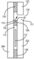
図3〜図6は、層、製品、シールゾーンおよびシールされていない領域の関係を説明することを補助するためのパッケージ100の概略的な断面図であり、実寸で描かれていない。例えば、図3〜図6において、シールされていない製品領域110およびシールされていないヘッダ部分116は、これらの領域において2つの層の間にシールが存在しないことを示すために、第1および第2の層の間に間隙を有するように示されている。しかしながら、現実には、第1および第2の層は、おそらく、シールされていない製品領域110において(製品112が介在しているところを除く)およびシールされていないヘッダ部分116において、互いにシールされていないが、互いに接触している。図3〜図6の概略図において、製品シールゾーン106は、理解しやすくするために別個の構造であるように見えるが、現実には、これは、別個の構造ではない層の間の結合を表している。
3-6 are schematic cross-sectional views of the
図3は、1つの実施の形態による、図1における3−3線に沿うパッケージ100の断面図である。両層202,204が同じ外側境界を有するように、第1の層202を第2の層204と揃えることができる。様々な実施の形態において、第1の層202は、第2の層204と同じ寸法を有することができる。幾つかの実施の形態において、第1の層202は、第2の層204と同じ材料を含むことができる。幾つかの実施の形態において、第1の層202は、第2の層204と同じ形状を有することができる。幾つかの実施の形態において、第1の層202は、第2の層204と同じ厚さを有することができる。様々な実施の形態において、第1の層202は、第2の層204と実質的に同じであることができる。図3は、第1の層202における第1のタブ切込み126を示している。第2のタブ切込み128は示されていない。なぜならば、図3の断面図は、パッケージの第1のタブ側を向いているからである。この図において、製品シールゾーン106は断面図で示されているが、第1のタブシールゾーン130は側面図で示されている。第1の層202における第1の境界部分101は、製造プロセスの間に第1のタブ切込み126が第1の層202に形成されるとき、第1のタブ122から切り離される。しかしながら、第1の境界部分101は、第2のタブ124(図3に示されていない)に連続している。なぜならば、第1の層202および第2の層204は、第2のタブシールゾーン132において互いにシールされているからである。
FIG. 3 is a cross-sectional view of the
図4は、パッケージが開封されようとしているときの図3の断面図を示している。図4の視点から、第2のタブ124(図示せず)は、第1のタブ122から反対方向へ引き離されている。第1の境界部分101は、第2のタブ124の力によって第1のタブ122から引き離される。なぜならば、第1の境界部分101は第2のタブ124に連続しているからである。第2のタブ124を第1のタブ122から引き離すために十分な大きさの力が使用者によって加えられると、製品シールゾーン106の頂点150においてシールが破壊される。
FIG. 4 shows a cross-sectional view of FIG. 3 when the package is about to be opened. From the viewpoint of FIG. 4, the second tab 124 (not shown) is pulled away from the
図5は、図3の反対の図を示している。図5は、図1における5−5線に沿ったパッケージの断面図を示している。図5は、第2の層204における第2のタブ切込み128を示している。図5は、さらに、第2のタブ切込み128の上方の第2のタブ124を示している。第1のタブ切込み126は示されていない。なぜならば、図5の断面図は、パッケージの第2のタブ側を向いているからである。この図において、製品シールゾーン106は断面図で示されているが、第2のタブシールゾーン132は側面図で示されている。第2の層204における第2の境界部分501は、図3に示された第1の境界部分101と同様である。第2の境界部分501は、製造プロセスの間に第2のタブ切込み128が第2の層204に形成されるとき、第2のタブ124から切り離される。第2の境界部分501は、第1のタブ122(図5に示されていない)に連続している。なぜならば、第1の層202および第2の層204は、第1のタブシールゾーン130において互いにシールされているからである。
FIG. 5 shows the opposite of FIG. FIG. 5 shows a cross-sectional view of the package along line 5-5 in FIG. FIG. 5 shows a
図6は、図4と同様に、パッケージが開封されているときの図5の断面図を示している。図6の視点から、第1のタブ122(図示せず)は、第2のタブ124から反対方向へ引き離されている。第2の境界部分501は、第1のタブ122の力によって第2のタブ124から引き離される。なぜならば、第2の境界部分501は第1のタブ122に連続しているからである。第1のタブ122を第2のタブ124から引き離すために十分な大きさの力が使用者によって加えられると、製品シールゾーン106の頂点150においてシールが破壊される。
FIG. 6 shows a cross-sectional view of FIG. 5 when the package is opened, similar to FIG. From the viewpoint of FIG. 6, the first tab 122 (not shown) is separated from the
図7は、1つの実施の形態によるパッケージ700の正面図を示している。パッケージ700は、製品シールゾーン706と、シールされていないパウチ領域710と、第1のタブ722と、第2のタブ724と、第1のタブ切込み726と、第2のタブ切込み728とを有することができる。パッケージ700は、隙間720を画定していることができる。
FIG. 7 shows a front view of the
幾つかの実施の形態において、パッケージ700は、1つまたは複数の触覚特徴部734を含むことができる。幾つかの実施の形態において、触覚特徴部734は、第1の層202および第2の層204の両方を貫通した1つまたは複数のスリットまたは切込みを有することができる。スリットは、使用者の手が滑ることなく使用者がタブを保持しかつ引っ張る能力を高めることができる。このような触覚特徴部は、使用者が、微細運動段階にある、部分的に障がいを持つ、手袋をはめている、または濡れている、または滑りやすい環境において作業しているとき、特に有利であることができる。幾つかの実施の形態において、スリットはV字形であることができる。幾つかの実施の形態において、触覚特徴部734は、1つよりも多いスリットまたは切込みを有することができる。幾つかの実施の形態において、触覚特徴部734は、3つのV字形スリットなどの、少なくとも3つのスリットを有することができる。幾つかの実施の形態において、各スリットは互いに同じであることができる。幾つかの実施の形態において、スリットは、第1の層202または第2の層204から材料を除去することによって画定されていない。スリットは、切断することなどによって、層の複数の部分を、それら自体から分離させることによって、画定することができる。
In some embodiments, the
図8は、1つの実施の形態によるパッケージ800の正面図を示している。パッケージ800は、製品シールゾーン806と、シールされていないパウチ領域810と、第1のタブ822と、第2のタブ824と、第1のタブ切込み826と、第2のタブ切込み828とを有することができる。パッケージ800は、隙間820を画定していることができる。
FIG. 8 shows a front view of the
幾つかの実施の形態において、パッケージ800は、1つまたは複数の触覚特徴部834を含むことができる。幾つかの実施の形態において、触覚特徴部834は、楕円形の開口であることができる。開口は、第1の層202および第2の層204の両方を貫通していることができる。幾つかの実施の形態において、開口は、使用者が、彼または彼女の指先の全部または一部を開口に挿入することができるように構成されている。幾つかの実施の形態において、触覚特徴部834は、触覚特徴部834が配置されているタブの面積の少なくとも25%を占めていることができ、例えば、開口は、タブの面積の25%をカバーしているか、または除去している。幾つかの実施の形態において、触覚特徴部834は、触覚特徴部が配置されているタブの面積の少なくとも50%を占めていることができる。
In some embodiments, the
図9は、1つの実施の形態によるパッケージ900の正面図を示している。パッケージ900は、第1の層902および第2の層904(図10に示されている)を含むことができる。パッケージ900は、製品シールゾーン906、シールされていないパウチ領域910、第1のタブ922、第2のタブ924、第1のタブ切込み926、第2のタブ切込み928、第1のタブシールゾーン930および第2のタブシールゾーン932を含むことができる。パッケージ900は隙間920を画定していることができる。幾つかの実施の形態において、パッケージ900は、1つまたは複数の触覚特徴部934を含むことができる。幾つかの実施の形態において、触覚特徴部934は、図8に示されかつ図8に関して説明されたものと同様の、ただし鈍化エレメント935をも含む開口を画定していることができる。鈍化エレメント935は、触覚特徴部934が、第1および第2の層を貫通した開口を含むときなどに、触覚特徴部934のエッジを鈍らせるまたは丸みづけることができる。鈍化エレメント935は、触覚特徴部934のエッジの鋭利さを低減するように構成することができる。鈍化エレメント935は、1つまたは複数のフィン切込み936によって分離された2つ以上のフィンを有する。これらのフィンは、使用者の指が鈍化エレメントと相互作用したときに曲がり、これにより、切断エッジではなく、折り曲げられたエッジが使用者の指に接触する。鈍化エレメントは、フィンを曲げやすくするひだ937も有する。鈍化エレメント935は、開口エッジの一部に沿って位置付けられている。幾つかの実施の形態において、鈍化エレメントは、第1または第2の層のうちの少なくとも一方の折り曲げられた部分を含む。
FIG. 9 shows a front view of the
図10は、図9における10−10線に沿うパッケージ900の断面図を示している。図10は、使用者の指が鈍化エレメント936に接触するときのように、ひだ線937に沿って折り曲げられた曲げ位置における鈍化エレメント935を示している。幾つかの実施の形態において、鈍化エレメント935は、第2の層904によってシールされた第1の層902を有するパッケージ900の一部にわたって折り曲げることを含むことができ、これにより、一方の層は、それ自体の上へ折り返され(図10における第2の層904)、他方の層(図10における第1の層902)は、ひだ937において触覚特徴部934のエッジまたは部分を画定する。幾つかの実施の形態において、パッケージ900は、パッケージ900が製造されるときに鈍化エレメント935としての折り曲げられた部分を有することができる。代替的な実施の形態において、使用者の指は、パッケージ900を開封する前に、鈍化エレメント935を形成するように、パッケージ900の指定された部分の折曲げを生じさせることができる。
FIG. 10 shows a cross-sectional view of the
図11は、1つの実施の形態によるパッケージ1100の正面図を示している。パッケージ1100は、製品シールゾーン1106と、シールされていないパウチ領域1110と、第1のタブ1122と、第2のタブ1124と、第1のタブ切込み1126と、第2のタブ切込み1128とを含むことができる。パッケージ1100は、隙間1120を画定していることができる。
FIG. 11 shows a front view of the
幾つかの実施の形態において、パッケージ1100は、1つまたは複数の触覚特徴部1134を含むことができる。幾つかの実施の形態において、触覚特徴部1134は、図11および図12に示されているように、隆起した突起を含むことができる。図12は、図11におけるパッケージ1100の一部の断面図を示している。突出した突起は、パッケージ1100を開封させるときに使用者によって掴むことができる。幾つかの実施の形態において、第1のタブ1122は、1つの隆起した突起を有し、第2のタブ1124は、1つの隆起した突起を有する。幾つかの実施の形態において、第1のタブ1122の隆起した突起は、パッケージの、第2のタブ1124の隆起した突起と同じ側にあることができる。代替的な実施の形態において、第1のタブ1122の隆起した突起は、突起が反対方向に延びることができるように、パッケージ1100の、第2のタブ1124の隆起した突起と反対側にあることができる。
In some embodiments,
幾つかの実施の形態において、第1のタブ1122は、パッケージの各側に1つなど、2つの隆起した突起を含む。様々な実施の形態において、第2のタブ1124も、パッケージ1100の互いに反対の側に2つの隆起した突起を有することができ、これにより、各タブ1122,1124がパッケージ1100の各側に1つの隆起した突起を有する。
In some embodiments, the
図13は、1つの実施の形態によるパッケージ1300の正面図を示している。パッケージ1300は、製品シールゾーン1306と、シールされていないパウチ領域1310と、第1のタブ1322と、第2のタブ1324と、第1のタブ切込み1326と、第2のタブ切込み1328とを含むことができる。パッケージ1300は、隙間1320を画定していることができる。
FIG. 13 shows a front view of the
幾つかの実施の形態において、パッケージ1300は、1つまたは複数の触覚特徴部1334を含むことができる。幾つかの実施の形態において、触覚特徴部1134は、図13および図14に示されているように、複数の隆起した突起を含むことができる。幾つかの実施の形態において、第1のタブ1322は、パッケージ1300の一方の側に複数の隆起した突起を含むことができる。幾つかの実施の形態において、第1のタブ1322は、(図14に示されているように)パッケージ1300の両方の側に複数の隆起した突起を含むことができる。第2のタブ1324も、パッケージ1300の一方または両方の側に複数の隆起した突起を含むことができる。幾つかの実施の形態において、第1のタブ1322は、パッケージ1300の一方の側に複数の隆起した突起を含むことができ、第2のタブ1324は、パッケージ1300の他方の側に複数の隆起した突起を含むことができる。幾つかの実施の形態において、複数の隆起した突起を、縦横の列で配置された突起を有するなど、反復するパターンで配置することができる。
In some embodiments, the
図15は、幾つかの実施の形態によるパッケージ1500の正面図を示している。パッケージ1500は、製品シールゾーン1506と、シールされていないパウチ領域1510と、第1のタブ1522と、第2のタブ1524と、第1のタブ切込み1526と、第2のタブ切込み1528とを含むことができる。パッケージ1500は、隙間1520を画定していることができる。
FIG. 15 shows a front view of the
幾つかの実施の形態において、パッケージ1500は、1つまたは複数の触覚特徴部1534を含むことができる。幾つかの実施の形態において、触覚特徴部1534は、反復する切り返し部分を含むパッケージの部分などの、ジグザグ部分を含むことができる。図16に示されているように、複数の切り返し部分を形成するために、第1および第2の層の折曲げまたはひだ部分によって、パッケージ1500に模様を画定することができる。
In some embodiments,
様々な実施の形態において、パッケージは、第1の層および/または第2の層に1つまたは複数の刻み目を含むことができる。刻み目は、シールされていないパウチ領域内の製品へアクセスするなどのために、層の一部を層の隣接する部分から裂断または分離させることを促進する、層のミシン目、溝または弱められた部分を含むことができる。幾つかの実施の形態において、刻み目は、レーザ刻み目であることができ、たとえば、層内で焼かれ、または溶融させられている。刻み目を含む幾つかの実施の形態において、パッケージは、シールゾーンに沿って層を分離させることなどをせずに、製品へアクセスするために刻み目に沿って層のうちの一方または両方を裂断させることによって開封することができる。第1および/または第2の層に刻み目を付けること含む幾つかの実施の形態において、製品シールゾーンは、剥離不能なシールを有することができ、これにより、剥離不能なシールであるシールの一部に沿って2つの層を分離させようとすると、結果として、シールに隣接した層の部分が裂断または破壊させられる。 In various embodiments, the package can include one or more notches in the first layer and / or the second layer. Notches are perforations, grooves or weakened layers that facilitate the tearing or separation of parts of the layer from adjacent parts of the layer, such as to access products in unsealed pouch areas. Can include parts. In some embodiments, the nicks can be laser knurls, for example, burned or melted within the layer. In some embodiments that include nicks, the package tears one or both of the layers along the nicks to access the product, without separating the layers along the seal zone, etc. It can be opened by letting it open. In some embodiments, including nicking the first and / or second layer, the product seal zone can have a non-peelable seal, thereby one of the seals which is a non-peelable seal. Attempting to separate the two layers along the section results in tearing or breaking of the portion of the layer adjacent to the seal.
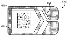
図17〜図19は、パッケージ1900の1つの実施の形態を示している。図17は、パッケージ1900のための第1の層1702の正面図を示している。図18は、パッケージ1900のための第2の層1804の正面図を示している。図19は、第1の層1702および第2の層1804を有するパッケージ1900の正面図を示している。
17-19 show one embodiment of
幾つかの実施の形態において、第1の層1702は、パッケージの一方の側部エッジに沿うとともに、シールされていないパウチ領域の側部エッジに沿って延びる第1の刻み目1770を含むことができる。第1の層1702は、パッケージの一方の側部エッジに沿うとともに、シールされていないパウチ領域の側部エッジに沿って延びる第2の刻み目1772をさらに含むことができる。第1の層1702は、タブ切込み1726をさらに含むことができる。幾つかの実施の形態において、第1の刻み目および第2の刻み目は、図17〜図19に示されているように、パッケージの一方の端部からパッケージの反対側の端部まで延びている。幾つかの実施の形態において、タブ切込み1726は、隙間から刻み目1770,1772のうちの一方まで延びていることができる。
In some embodiments, the
第1の層1702と同様に、第2の層1804は、第1の刻み目1874を含むことができ、幾つかの実施の形態において、第2の刻み目1876を含むことができる。様々な実施の形態において、第1の刻み目1874および第2の刻み目1876は平行であることができる。様々な実施の形態において、第1の刻み目1874および第2の刻み目1876はそれぞれ、パッケージの一方の端部からパッケージの反対側の端部まで延びていることができる。第2の層1804も、タブ切込み1828を含むことができる。タブ切込み1828は、隙間から刻み目1874,1876のうちの一方まで延びていることができる。
Like the
図19は、第1の層1702を上にした正面図でパッケージ1900を示している。パッケージ1900は、第1の層1702において第1の刻み目1770および第2の刻み目1772を有する。パッケージ1900は、第2の層において第1の刻み目1874および第2の刻み目1876をさらに含むことができる。パッケージ1900は、2つのタブ切込み1726および1828を含むことができる。パッケージ1900は、使用者がタブを反対方向へ引っ張り、層における刻み目のうちの一方または両方に沿って第1の層1702および/または第2の層1804を裂断させることによって、開封させることができる。
FIG. 19 shows the
図20〜図22は、パッケージ2200の1つの実施の形態を示している。図20は、パッケージ2200のための第1の層2002の正面図を示している。図21は、パッケージ2200のための第2の層2104の正面図を示している。図22は、第1の層2002および第2の層2104を含むパッケージ2200の正面図を示している。
20-22 show one embodiment of
幾つかの実施の形態において、第1の層2002は第1の刻み目2070を含むことができ、第1の刻み目2070は、層2002のエッジまたは周縁部と交差しないように層2002内に延びている。幾つかの実施の形態において、第1の刻み目2070は、シールされていないパウチ領域内へ延びていることができる。幾つかの実施の形態において、第1の刻み目2070は、タブシールゾーンと製品シールゾーンとの間のシールされていない領域から、シールされていないパウチ領域まで延びていることができる。第1の層2002は、さらに、タブ切込み2026を含むことができる。幾つかの実施の形態において、タブ切込み2026は、隙間から刻み目2070まで延びていることができる。
In some embodiments, the
第1の層2002と同様に、第2の層2104は刻み目2174を含むことができる。刻み目2174は、刻み目2070と同様に、シールされていないパウチ領域内の、開封中に製品が露出させられ、パッケージから取り出されることができるようになる後の箇所などにおいて、途切れていることができる。第2の層2104も、タブ切込み2128を含むことができる。タブ切込み2128は、隙間から刻み目2174まで延びていることができる。
Like the
図22は、第1の層2002における刻み目2070と、第2の層2104における刻み目2174とを備えるパッケージ2200を示している。パッケージ2200は、2つのタブ切込み2026および2128を有することができる。パッケージ2200は、使用者がタブを反対方向へ引っ張り、それぞれの層における刻み目に沿って第1の層2002および/または第2の層2104を引き剥がすことによって、開封させることができる。
FIG. 22 shows a
図23は、製品シールゾーン2306の異なる実施の形態を備えるパッケージ2300の正面図を示している。製品シールゾーン2306は、第2の層に接合された第1の層のより多くの領域を含むシールゾーンの一部などの、突出部分2380を含むことができる。突出部分2380は、シールゾーン2306の隣接する部分と比較して、パッケージ2300を開封させるために使用者が付加的な力を加えることを要求することができる。突出部分2380は、使用者がパッケージを開封しているとき、突出部分2380において層を分離させることなく製品がパッケージから取り出されることができるように、配置することができる。突出部分2380は、パッケージ2300をさらに開封させることなく、また、製品がパッケージ2300から飛び出るリスクを増大することなく、製品がパッケージ2300から取り出されることができることに使用者が気付かされるように付加的な力を要求することができる。
FIG. 23 shows a front view of the
幾つかの実施の形態において、力の増大は、製品シールゾーンの隣接する部分と比較したとき、第1の位置において製品シールゾーンに沿って層を分離させるために要求されることができる。幾つかの実施の形態において、シールはタイトであることができ、これにより、シールは、製品の、ヘッダとは反対側にあるシールの部分に沿って層を分離させるためにより大きな力を要求する。幾つかの実施の形態において、よりタイトなシールは、層を互いにシールするときにより大きな圧力が加えられることによって形成することができる。 In some embodiments, an increase in force can be required to separate the layers along the product seal zone in the first position when compared to the adjacent portion of the product seal zone. In some embodiments, the seal can be tight, whereby the seal requires greater force to separate the layers along the portion of the seal opposite the header of the product. .. In some embodiments, a tighter seal can be formed by applying greater pressure when sealing the layers together.
図24は、1つの実施の形態によるパッケージの正面図である。幾つかの実施の形態において、パッケージ100は、少なくとも1.5インチかつ9インチ以下の長さ(L)を有することができる。幾つかの実施の形態において、パッケージ100は、少なくとも1.5インチかつ6インチ以下の長さ(L)を有することができる。幾つかの実施の形態において、パッケージ100は、少なくとも2インチかつ6インチ以下の長さ(L)を有することができる。幾つかの実施の形態において、パッケージ100は、少なくとも2.5インチかつ5.5インチ以下の長さ(L)を有することができる。幾つかの実施の形態において、パッケージ100は、少なくとも3インチかつ4.5インチ以下の長さ(L)を有することができる。幾つかの実施の形態において、パッケージ100は、約3.5インチの長さ(L)を有することができる。幾つかの実施の形態において、パッケージ100は、約4インチの長さ(L)を有することができる。幾つかの実施の形態において、パッケージ100は、約8インチの長さ(L)を有することができる。
FIG. 24 is a front view of the package according to one embodiment. In some embodiments, the
幾つかの実施の形態において、パッケージ100は、少なくとも1.5インチの長さ(L)を有することができる。幾つかの実施の形態において、パッケージ100は、少なくとも2インチの長さ(L)を有することができる。幾つかの実施の形態において、パッケージ100は、少なくとも2.5インチの長さ(L)を有することができる。幾つかの実施の形態において、パッケージ100は、少なくとも3インチの長さ(L)を有することができる。
In some embodiments, the
幾つかの実施の形態において、パッケージ100は、4.5インチ以下の長さ(L)を有することができる。幾つかの実施の形態において、パッケージ100は、5.5インチ以下の長さ(L)を有することができる。幾つかの実施の形態において、パッケージ100は、6インチ以下の長さ(L)を有することができる。幾つかの実施の形態において、パッケージ100は、9インチ以下の長さ(L)を有することができる。
In some embodiments, the
幾つかの実施の形態において、パッケージ100は、少なくとも1インチかつ5インチ以下の幅(W)を有することができる。幾つかの実施の形態において、パッケージ100は、少なくとも1インチかつ4インチ以下の幅(W)を有することができる。幾つかの実施の形態において、パッケージ100は、少なくとも1インチかつ3インチ以下の幅(W)を有することができる。幾つかの実施の形態において、パッケージ100は、少なくとも1.5インチかつ2.5インチ以下の幅(W)を有することができる。幾つかの実施の形態において、パッケージ100は、1.95インチなどの約2インチの幅(W)を有することができる。幾つかの実施の形態において、パッケージ100は、3.9インチなどの約4インチの幅(W)を有することができる。
In some embodiments, the
幾つかの実施の形態において、パッケージ100は、少なくとも1インチの幅(W)を有することができる。幾つかの実施の形態において、パッケージ100は、少なくとも1.5インチの幅(W)を有することができる。幾つかの実施の形態において、パッケージ100は、少なくとも1.75インチの幅(W)を有することができる。
In some embodiments, the
幾つかの実施の形態において、パッケージ100は、5インチ以下の幅(W)を有することができる。幾つかの実施の形態において、パッケージ100は、4インチ以下の幅(W)を有することができる。幾つかの実施の形態において、パッケージ100は、3インチ以下の幅(W)を有することができる。幾つかの実施の形態において、パッケージ100は、2.5インチ以下の幅(W)を有することができる。
In some embodiments, the
幾つかの実施の形態において、隙間120は、パッケージ100の長さの少なくとも10%だけ延びていることができる。幾つかの実施の形態において、隙間120は、パッケージ100の長さの少なくとも15%だけ延びていることができる。幾つかの実施の形態において、隙間120は、パッケージ100の長さの少なくとも20%だけ延びていることができる。幾つかの実施の形態において、隙間120は、パッケージ100の長さの少なくとも25%だけ延びていることができる。
In some embodiments, the
幾つかの実施の形態において、第1のタブシールゾーン130および第2のタブシールゾーン132は、同じ長さ(l)を有することができる。幾つかの実施の形態において、第1のタブシールゾーン130または第2のタブシールゾーン132は、パッケージ100の端部から、第1のタブシールゾーン130の最も遠い部分または第2のタブシールゾーン132の最も遠い部分までの長さ(l)を有することができる。幾つかの実施の形態において、第1のタブシールゾーン130または第2のタブシールゾーン132は、少なくとも1インチかつ3.5インチ以下の長さ(l)を有することができる。幾つかの実施の形態において、第1のタブシールゾーン130または第2のタブシールゾーン132は、少なくとも1インチかつ2インチ以下の長さ(l)を有することができる。幾つかの実施の形態において、第1のタブシールゾーン130または第2のタブシールゾーン132は、少なくとも1.5インチかつ1.75インチ以下の長さ(l)を有することができる。幾つかの実施の形態において、第1のタブシールゾーン130または第2のタブシールゾーン132は、約1.65インチの長さ(l)を有することができる。幾つかの実施の形態において、第1のタブシールゾーン130または第2のタブシールゾーン132は、少なくとも0.5インチかつ3インチ以下の長さ(l)を有することができる。幾つかの実施の形態において、第1のタブシールゾーン130または第2のタブシールゾーン132は、少なくとも0.75インチかつ1.5インチ以下の長さ(l)を有することができる。幾つかの実施の形態において、第1のタブシールゾーン130または第2のタブシールゾーン132は、少なくとも1インチかつ1.25インチ以下の長さ(l)を有することができる。幾つかの実施の形態において、第1のタブシールゾーン130または第2のタブシールゾーン132は、約1.15インチの長さ(l)を有することができる。幾つかの実施の形態において、第1のタブシールゾーン130または第2のタブシールゾーン132は、約3.3インチの長さ(l)を有することができる。
In some embodiments, the first
幾つかの実施の形態において、第1のタブシールゾーン130または第2のタブシールゾーン132は、少なくとも0.5インチの長さ(l)を有することができる。幾つかの実施の形態において、第1のタブシールゾーン130または第2のタブシールゾーン132は、少なくとも0.75インチの長さ(l)を有することができる。幾つかの実施の形態において、第1のタブシールゾーン130または第2のタブシールゾーン132は、少なくとも1インチの長さ(l)を有することができる。幾つかの実施の形態において、第1のタブシールゾーン130または第2のタブシールゾーン132は、少なくとも1.5インチの長さ(l)を有することができる。
In some embodiments, the first
幾つかの実施の形態において、第1のタブシールゾーン130または第2のタブシールゾーン132は、1.25インチ以下の長さ(l)を有することができる。幾つかの実施の形態において、第1のタブシールゾーン130または第2のタブシールゾーン132は、1.5インチ以下の長さ(l)を有することができる。幾つかの実施の形態において、第1のタブシールゾーン130または第2のタブシールゾーン132は、1.75インチ以下の長さ(l)を有することができる。幾つかの実施の形態において、第1のタブシールゾーン130または第2のタブシールゾーン132は、2インチ以下の長さ(l)を有することができる。幾つかの実施の形態において、第1のタブシールゾーン130または第2のタブシールゾーン132は、3インチ以下の長さ(l)を有することができる。幾つかの実施の形態において、第1のタブシールゾーン130または第2のタブシールゾーン132は、3.5インチ以下の長さ(l)を有することができる。
In some embodiments, the first
幾つかの実施の形態において、第1のタブ切込み126と第1のタブシールゾーン130との間のスペース(d)または第2のタブ切込み128と第2のタブシールゾーン132との間のスペース(d)は、少なくとも0.05インチかつ0.5インチ以下であることができる。幾つかの実施の形態において、第1のタブ切込み126と第1のタブシールゾーン130との間のスペース(d)または第2のタブ切込み128と第2のタブシールゾーン132との間のスペース(d)は、少なくとも0.1インチかつ0.25インチ以下であることができる。幾つかの実施の形態において、第1のタブ切込み126と第1のタブシールゾーン130との間のスペース(d)または第2のタブ切込み128と第2のタブシールゾーン132との間のスペース(d)は、約0.28インチ、0.15インチまたは0.14インチであることができる。
In some embodiments, the space (d) between the
幾つかの実施の形態において、第1のタブ切込み126と第1のタブシールゾーン130との間のスペース(d)または第2のタブ切込み128と第2のタブシールゾーン132との間のスペース(d)は、少なくとも0.05インチであることができる。幾つかの実施の形態において、第1のタブ切込み126と第1のタブシールゾーン130との間のスペース(d)または第2のタブ切込み128と第2のタブシールゾーン132との間のスペース(d)は、少なくとも0.1インチであることができる。
In some embodiments, the space (d) between the
幾つかの実施の形態において、第1のタブ切込み126と第1のタブシールゾーン130との間のスペース(d)または第2のタブ切込み128と第2のタブシールゾーン132との間のスペース(d)は、0.5インチ以下であることができる。幾つかの実施の形態において、第1のタブ切込み126と第1のタブシールゾーン130との間のスペース(d)または第2のタブ切込み128と第2のタブシールゾーン132との間のスペース(d)は、0.25インチ以下であることができる。
In some embodiments, the space (d) between the
第1の層202および第2の層204は、技術分野において一般的に知られている様々な材料および材料の組合せ、例えば、ポリエステルフィルム、スパンボンデッドオレフィン、DuPont TYVEK(登録商標)ブランドスパンボンデッドオレフィン、ポリブチレンを備える線状低密度ポリエチレン、二軸延伸ポリエステルフィルム、ポリプロピレンフィルム、高密度ポリエチレンフィルム、アクリロニトリルコポリマーフィルム、BP Chemicals, Inc.から提供されているBAREX(登録商標)ブランドアクリロニトリルコポリマーフィルム、キャストポリエチレンテレフタラート(PET)またはポリエチレンテレフタラートグリコール(PETG)フィルム、金属箔、アルミニウム箔、ポリ二塩化ビニリデン(PVDC)フィルム、エチレンビニルアルコールポリマ(EVOH)を含有する共押出フィルム、ポリビニルアルコール(PVA)フィルム、ポリアミドフィルム、ビニルフィルム、高密度ポリエチレン(HDPE)、ACLAR(登録商標)ブランドフィルム、冷間成形または熱成形フィルム、多層ヒートシール可能パウチフィルムまたは同じものを含有する複合ラミネーションまたはコーティングを含むことができる。様々な実施の形態において、第1の層202および第2の層204は、ヒートシール可能であるか、または超音波溶接、圧力または振動を利用してシール可能である。幾つかの実施の形態において、第1の層202および第2の層204のうちの一方のみがヒートシール可能であり、他方は、剥離可能シールを形成するための適合性材料である。1つの実施の形態において、第1および第2の層202,204のそれぞれは、DuPont TYVEK(登録商標)ブランドスパンボンデッドオレフィン、結合層およびシーラント層などのポリエステル層を含む。1つの実施の形態において、ポリエステルフィルム、結合層およびシーラント層は、1つのフィルムを形成するために共押出または積層されている。適切なシーラント層の1つの例は、他方の層に結合するために熱によって活性化される、ポリブチレンを備えた線状低密度ポリエチレンである。幾つかの実施の形態において、層202,204は、ヒートシーリング以外の方法によって接合される。例えば、層202,204は、幾つかの実施の形態において超音波溶接によって接合されてもよい。幾つかの実施の形態において、層202,204は、ヒートシーリングおよび超音波溶接の両方などの、1つより多い方法によって接合されてもよい。
The
様々な実施の形態において、第1の層202および第2の層204は、実質的に不透過性である。様々な実施の形態において、第1の層202および第2の層204は、実質的に透過性である。例えば、金属箔層を含む層は実質的に不透過性であるのに対し、DuPont TYVEK(登録商標)ブランドスパンボンデッドオレフィンを含む層は透過性である。様々な実施の形態において、第1の層202および第2の層204は実質的に可撓性であるが、幾つかの実施の形態において、第1の層202または第2の層204の一方または両方は、実質的に剛性である。幾つかの実施の形態において、層のうちの一方または両方は、製品112が透明層を通して見えるように、透明である。第1の層202および第2の層204を表すために使用することができる代替的な用語は、フィルム、シート、ウェブ等を含む。
In various embodiments, the
第1の層202は、概して第2の層204と同じ広がりを持ち、上述のように、第1の層202および第2の層204は、剥離可能シールによって少なくとも部分的に接合されている。概して、剥離可能シールは、第1の層202および第2の層204の接触面の間の密封接合である。剥離可能シールは、技術分野において公知のあらゆる適切な方法によって形成することができる。様々な実施の形態において、剥離可能シールは、熱および圧力を加えることによって生じる、ヒートシールまたはメルトボンドされた関係である。代替的な実施の形態において、剥離可能シールは、第1の層202および第2の層204の接触面のうちの少なくとも一方に提供された適切な接着剤によって形成されている。少なくとも1つの実施の形態において、剥離可能シールは再シール可能であり、これにより、使用者はパッケージ100を再封鎖することができる。
The
概して、剥離可能シールは、使用者が、工具を使用することなく第1の層202および第2の層204を剥離させ、それらの間の製品112へアクセスすることができるようにする強度を有するように構成されている。1つの実施の形態において、剥離可能シールの強度は、パルプ製紙産業技術協会によって出版された試験手順TAPPI T-494にしたがって、毎分12インチの走行速度で180度において引き離したときのシールの線形インチ当たり1.25〜2ポンドの範囲である。幾つかの実施の形態において、剥離可能シールの強度は、シールの線形インチ当たり1.0〜2.5ポンドの範囲である。様々な実施の形態において、剥離可能シールは、シールの線形インチ当たり0.25〜3.5インチの範囲の強度を有する。
In general, the peelable seal has the strength to allow the user to peel off the
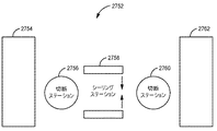
図25は、本明細書に開示された技術と一致するパッケージを製造する1つの方法と一致するフローチャートを示している。概して、少なくとも2つのウェブが提供され(20)、製品が一方のウェブに配置され(30)、シールされていない領域内に製品を閉じ込めるためにウェブがシールされ(40)、次いで、ウェブがパッケージに切断され(50)、隙間が切込みによって画定され、タブ切込みが形成される。図26は、切断(50)の前の、図25に関連した方法と一致する、複合ウェブ1000の一例を示している。これらの構成部分から形成されたパッケージは、製品を収容および提供するためのものであることができる。
FIG. 25 shows a flow chart consistent with one method of manufacturing a package consistent with the techniques disclosed herein. Generally, at least two webs are provided (20), the product is placed on one web (30), the web is sealed to confine the product within the unsealed area (40), then the web is packaged. (50), the gap is defined by the notch and a tab notch is formed. FIG. 26 shows an example of a
ウェブを提供するステップ(20)は、概して、第1の層ウェブおよび第2の層ウェブを提供することを含むが、付加的なウェブを提供することもできる。第1の層ウェブおよび第2の層ウェブは、本明細書に記載されているように、様々な異なる材料であることができる。製品を配置すること(30)は、概して、第2の層ウェブの少なくとも1つのパウチ領域に製品を配置することを含む。 The web-providing step (20) generally includes providing a first-tier web and a second-tier web, but additional webs can also be provided. The first layer web and the second layer web can be a variety of different materials as described herein. Placing the product (30) generally involves placing the product in at least one pouch area of the second layer web.
図26は、第1の層ウェブおよび第2の層ウェブを有する複合ウェブ1000を示している。複合ウェブ1000は、個々のパッケージ2600を含み、各パッケージは、パウチ領域2610と、パウチ領域2610における製品112とを有する。個々のパッケージ2600は、ウェブマトリックス2646によって互いから分離されている。
FIG. 26 shows a
図26および図25のステップを参照すると、様々な実施の形態において、複数の製品112は、第2の層ウェブの対応するパウチ領域2610において第2の層ウェブに配置される。剥離可能シールによって第1の層が第2の層に接合されるように、少なくともシールゾーンのうちの1つにおいて第1の層ウェブを第2の層ウェブにシールすることによって、複合ウェブ1000を形成するためにウェブがステップ40においてシールされる。幾つかの実施の形態において、製品シールゾーン、第1のタブシールゾーンおよび第2のタブシールゾーンにおいて第1の層ウェブを第2の層ウェブとシールさせることができる。図26に示された実施の形態を含む複数の実施の形態において、複合ウェブを形成することは、第1のタブ内の第1のタブシールゾーンおよび第2のタブ内の第2のタブシールゾーンにおいて第1の層ウェブを第2の層ウェブにシールすることも含む。
Referring to the steps of FIGS. 26 and 25, in various embodiments, the plurality of
ウェブは、概して、複数のパッケージを作るための大きさにされており、加工方向に極めて長くてもよく、連続的と呼ばれてもよく、1〜5個のパッケージ分またはそれ以上の加工横断方向を有してもよい。図26の複合ウェブ1000は、2つのパッケージの幅を有し、加工方向に極めて長い。“加工方向で極めて長い”という表現は、その幅より100〜1000倍長いなど、幅広であるよりも一般的に実質的により長く、しばしばロールにおいて加工されるウェブを意味するために使用される。
The web is generally sized to make multiple packages, may be extremely long in the machining direction, may be referred to as continuous, and traverses 1 to 5 packages or more. It may have a direction. The
図25の方法の少なくとも1つの例としての実施において、ウェブをシールすること(40)は、連続動作機械のラインで行われる。複合ウェブ1000を形成するためにシールゾーンにおいてヒートシールまたはその他のシールによって第1の層ウェブと第2の層ウェブとを接合するためにシールプレートを使用することができる。このような実施において、シールプレート自体は、内側周縁部および外側周縁部を有する製品シールゾーンをも画定する。図26に示されたウェブ実施形態において、このようなシールプレートは、個々のパッケージタブ領域内に第1のタブシールゾーンおよび第2のシールゾーンも画定する。
In the implementation of at least one example of the method of FIG. 25, sealing the web (40) is performed on the line of a continuously operating machine. A seal plate can be used to join the first layer web to the second layer web by heat sealing or other sealing in the seal zone to form the
複合ウェブは次いで、少なくとも1つの個々のパッケージを製造するために切断される(50)。マトリックス2646から個々のパッケージ2600を分離させるために、中央の加工方向の切断線、加工横断方向の切断線、および外側の加工方向の切断線に沿ってパッケージが切断される。ウェブマトリックス2646は、シーリングおよび切断ステップにおいてある程度の公差を許容する。
The composite web is then cut to produce at least one individual package (50). To separate the
様々な実施の形態において、切断する工程のステップ(50)は、パッケージ2600に第1のタブを画定するために第1のタブ切込み位置においてパッケージの第1の層のみを切断する工程と、パッケージに第2のタブを画定するために第2のタブ切込み位置においてパッケージの第2の層のみを切断する工程も含む。上述のように、タブ切込みは、概して、製品シールゾーン、第1のタブシールゾーンおよび第2のタブシールゾーンの外側にあり、シールされていないヘッダ領域内にある。様々な実施の形態において、各個々のパッケージは、それぞれの外側周縁部の周りでかつタブ切込み位置において打ち抜かれる。各パッケージにタブ切込みを切断する工程に加え、各パッケージに隙間を切り抜くことができる。様々な実施の形態において、各個々のパッケージは、1つの打抜きステーションおよびステップにおいて、それぞれの外側周縁部の周りでかつタブ切込み位置において打ち抜かれる。少なくとも1つの例としての実施において、打抜き(50)は、ロータリーダイステーションにおいて実施される。このような例において、ロータリーダイは、例えば、アンビルロールに押し付けられて切断することができる。その他の実施の形態において、パッケージは、外側周縁部においてナイフ切断またはギロチン切断される。
In various embodiments, the cutting step (50) includes cutting only the first layer of the package at the first tab notch position to define the first tab in the
図27は、本明細書に記載されたパッケージを形成するために使用することができるパッケージ製造装置システム2752の1つの実施の形態の概略図である。システム2752は、第1の層、第2の層およびパッケージングされる製品などの、パッケージのための投入材料を提供するための機器2754を含む。1つの実施の形態において、これらの材料はロールで提供される。望まれるあらゆる準備的切断を行うために、幾つかの実施の形態において、シーリングステーション2758の前に予備ダイステーション2756が設けられてもよい。予備ダイステーション2756は、1つまたは複数のロータリーダイ、1つまたは複数のフラットダイまたはそれらの組合せを含むことができる。幾つかの実施の形態において、準備的切断が必要とされないなどの場合、シーリングステーション2758の前にダイステーション2756は存在しない。
FIG. 27 is a schematic representation of one embodiment of the package
シーリングステーション2758は、シールゾーンにおいてウェブを互いに接合するためにウェブをシールする工程のステップを行う。1つの実施の形態において、シーリングステーションは、異なるシールゾーンを形成するために使用される複数のヒートシールプレートを含む。1つの実施の形態において、第1のシールプレートは製品シールゾーンを形成するために使用されるが、第2のシールプレートは、第1のタブシールゾーンおよび第2のタブシールゾーンを形成するために使用される。様々な実施の形態において、シーリングステーション2758は、異なるシールゾーンを形成するために圧力法または超音波法を使用することができる。様々な実施の形態において、異なるシールゾーンを形成するために接着剤を塗布することができる。
The sealing
ダイステーション2760が設けられており、ここでは、個々のパッケージをマトリックスから分離させるために、かつ幾つかの実施の形態において2つのタブの間に隙間を画定するために、図26に関して説明したように、各パッケージが外側周縁部に沿って切断される。予備ダイステーション2760は、1つまたは複数のロータリーダイ、1つまたは複数のフラットダイまたはそれらの組合せを有することができる。パッケージは、また、第1のタブを形成するために第1のタブ切込み位置において一方の層において切断され、第2のタブを形成するために第2のタブ切込み位置において他方の層において切断される。プロセスにおいて製造された個々のパッケージを処理するために、排出機器2762も設けられている。図27の概略図は、基本的な機器構成部分を示しているが、付加的な機器がその他の処理機能を提供することができることが当業者によって認識されるであろう。
A
図28は、幾つかの実施の形態による、剥離抑制特徴部を有するパッケージの正面図である。図28は、製品2812を収容および提供するためのパッケージ2800を示している。幾つかの実施の形態において、パッケージ2800は、本明細書に記載された触覚特徴部と類似の触覚特徴部2834を含む。パッケージ2800は、第1の層2802、(図28における第1の層2802の裏側における)第2の層2804、シール2807によって第1の層2802が第2の層2804に接合されている製品シールゾーン2806とから構成されている。第1の層2802および第2の層2804は、上述の形式で互いに接合されている。
FIG. 28 is a front view of a package having a peeling suppression feature according to some embodiments. FIG. 28 shows a
特に、第1の層2802は、1つまたは複数のシールゾーンにおいて第2の層2804と接合させることができる。図28の実施の形態において、第1の層2802および第2の層2804は、第1のタブシールゾーン2830、第2のタブシールゾーン2832および製品シールゾーン2806においてシールされている。第1の層2802および第2の層2804は、シールされていない部分2816においてシールされていない。第1の層2802および第2の層2804は、シールされていないパウチ領域2810においてもシールされていない。
In particular, the
パッケージ2800は、パッケージ2800の一方の端部におけるヘッダゾーン2818と、ヘッダゾーン2818と反対側の閉鎖端部2819とを有する。ヘッダゾーン2818は、製品シールゾーン2806の外側周縁部2814に隣接している。ヘッダゾーン2818は、第1のタブ2822および第2のタブ2824を含む。ヘッダゾーン2818は、シールされていない部分2816も含む。第1のタブシールゾーン2830は、第1のタブ2822を画定している。第2のタブシールゾーン2832は、第2のタブ2824を画定している。第1のタブ2822と第2のタブ2824との間に、隙間2820がある。隙間2820は、第1のタブ2822を第2のタブ2824から分離するエッジ2821によって境界を定められている。幾つかの例において、第1のタブ切込み2826は、第2のタブ切込み2828と交差していない。これらの例において、第1のタブ切込み2826は、隙間2820の一部を画定するパッケージ2800のエッジ2821において途切れており、第2のタブ切込み2828も、パッケージ2800のエッジ2821において途切れている。
製品シールゾーン2806は、製品シールゾーン2806の境界を画定する、内側周縁部2808および外側周縁部2814を有する。製品シールゾーン2806の内側周縁部2808は、製品2812を収容するためのシールされていないパウチ領域2810を画定している。シール2807は、第1のシールエッジ2838および第2のシールエッジ2839を有する。閉鎖端部2819は、製品シールゾーン2806の端部と見なされる。シール2807は、製品2812を露出から保護している。
The
ヘッダゾーン2818は、ヘッダゾーン2818のシールされていない部分2816内の第1の層2802における第1のタブ切込み2826と、ヘッダゾーン2818のシールされていない部分2816内の第2の層2804における第2のタブ切込み2828と、も含む。図28の第2のタブ切込み2828は、破線として示されている。第1のタブ切込み2826および第2のタブ切込み2828により、使用者は、第1の層2802と第2の層2804とを剥離させ、製品2812を露出させることができる。
The
使用者は、一方の手で第1のタブ2822を、他方の手で第2のタブ2824を掴み、2つのタブを反対方向へ引っ張ることによって製品2812を露出させるためにパッケージ2800を開封する。最初、シール2807は分離に抵抗する。使用者がシール2807の抵抗に対して十分な力を加えると、力は、まず製品シールゾーン2806の頂点2850においてシール2807を破壊させる。第1の層2802は、次いで、第2の層2804から剥離し始める。第1のタブ2822および第2のタブ2824は、次第に引き離され、シール2807のより多くが破壊される。最後に、第1の層2802および第2の層2804が剥離されながら、第1のシールエッジ2838および第2のシールエッジ2839が破壊される。
The user opens the
幾つかの例において、使用者が製品2812を掴みかつ製品2812をパッケージから取り出すために十分にパッケージ2800が開封されると、層を分離させることができる速度を減速させることが望ましい。幾つかの例において、第1および第2の層が互いから完全に分離される可能性を減じることが望ましい。第1および第2の層が互いから完全に分離されることは、製品をパッケージから落下させることがある。こうするための1つの方法は、製品2812が次第に露出させるにしたがって、シール2807によって提供される抵抗を増大させることである。幾つかの例において、剥離抑制特徴部2880がこの機能を提供する。剥離抑制特徴部2880は、シール2807の抵抗を増大させ、第1の層2802と第2の層2804とを分離させるために使用者が付加的な力を加えることを要求する。実際には、使用者は、特定の大きさの力を加えることによって第1の速度でシール2807を引き離すことができる。第1の層と第2の層とが分離させられながら使用者が剥離抑制特徴部に達すると、剥離抑制特徴部が作動させられる。シール2807の抵抗が増大し、第1の層2802と第2の層2804との分離速度が減速する。これにより、剥離抑制特徴部2880はスピードバンプとして作用し、使用者があまりに速くパッケージ2800を剥離開封させることを防止する。使用者があまりに速くパッケージ2800を剥離開封させることは、時には、製品2812がパッケージ2800から床へ落下することにつながる。
In some examples, once the
図28の例において、剥離抑制特徴部2880は、広がったシールゾーン部分2883を有する。第1のシールエッジ2838は、広がったシールゾーン部分2883に隣接したシールゾーン部分2881において第1の幅2857を有する。広がったシールゾーン部分2883は、第1の幅2857より大きな第2の幅2855を有する。第2のシールエッジ2839は、同様に、より狭い部分2841およびより広い部分2842を有する。
In the example of FIG. 28, the peeling
実際には、使用者がパッケージを開封するとき、第1の層2802を第2の層2804から剥離させることは、シールを、より狭い部分2841と同時により狭い部分2838の位置において破壊させ、シールは、より広い部分2842と同時により広い部分2883の位置において破壊させられる。
In fact, when the user opens the package, stripping the
第1の層2802および第2の層2804が製品シールゾーン部分2881および2841において剥離されるとき、これは、特定の速度で層を引き離すための特定の大きさの力を要求する。使用者が、広がったシールゾーン部分2883および2842に達すると、剥離抑制特徴部が作動させられる。すなわち、広がったシールゾーン部分2883および2842において、より狭い部分2841および2881と同じ速度で第1の層と第2の層とを剥離させるために、より大きな力が要求される。その結果、使用者が均等な大きさの力を加えると、層が引き離される速度が、剥離抑制特徴部の位置において減速させられる。
When the
幾つかの例において、使用者が、製品シールゾーンの頂点からパッケージの後側エッジまでの距離の半分より多くパッケージの側部を剥離させたとき、剥離抑制特徴部が作動させられる。幾つかの例において、剥離抑制特徴部は、シールエッジまでの距離の半分、シールエッジまでの距離の3分の2またはシールエッジまでの距離の4分の3に配置されている。例えば、製品シールゾーンの頂点からパッケージの後側エッジまで3インチの長さを有するパッケージにおいて、剥離抑制特徴部は、頂点から1.5インチより大きい距離、頂点から1.75インチより大きい距離、頂点から2インチより大きい距離、頂点から2.25インチより大きい距離または頂点から2.5インチより大きい距離に配置することができる。 In some examples, the delamination restraint feature is activated when the user exfoliates the side of the package more than half the distance from the apex of the product seal zone to the posterior edge of the package. In some examples, the delamination restraint feature is located at half the distance to the seal edge, two-thirds the distance to the seal edge, or three-quarters the distance to the seal edge. For example, in a package having a length of 3 inches from the apex of the product seal zone to the posterior edge of the package, the peeling suppression feature may be greater than 1.5 inches from the apex, greater than 1.75 inches from the apex. It can be placed at a distance greater than 2 inches from the apex, a distance greater than 2.25 inches from the apex, or a distance greater than 2.5 inches from the apex.
剥離抑制特徴部の位置は、シールされていないパウチ領域に対する製品の位置に基づいて変動することができる。幾つかの例において、剥離抑制特徴部は、製品の後側エッジよりも、ヘッダゾーンの近くに配置されている。幾つかの例において、剥離抑制特徴部は、第1の層が第2の層から剥離されながら剥離抑制特徴部が作動させられたときに製品の一部が製品シール領域によってまだ包囲されているような位置に、配置されている。剥離抑制特徴部は、パッケージが剥離開封されながら剥離抑制特徴部が作動させられたときに製品の全部が露出させられないように配置することができる。 The position of the delamination restraint feature can vary based on the position of the product with respect to the unsealed pouch area. In some examples, the delamination restraint feature is located closer to the header zone than the posterior edge of the product. In some examples, the peel-inhibiting feature is still partially surrounded by the product seal region when the peel-inhibiting feature is activated while the first layer is stripped from the second layer. It is arranged in such a position. The peeling suppressing feature portion can be arranged so that the entire product is not exposed when the peeling suppressing feature portion is operated while the package is peeled and opened.
広がったシールゾーン部分の幅は、用途に応じて変動することができる。幾つかの例において、広がったシールゾーン部分は、隣接するシールゾーン部分より50%広い。幾つかの例において、広がったシールゾーン部分は、隣接するシールゾーン部分より10%から50%までの間で広く、隣接するシールゾーン部分より25%から75%までの間で広く、隣接するシールゾーン部分より50%から100%までの間で広く、隣接するシールゾーン部分より75%から125%までの間で広く、または隣接するシールゾーン部分より100%から150%までの間で広い。幾つかの例において、広がったシールゾーン部分は、隣接するシールゾーン部分より2倍以上広い。幾つかの例において、広がったシールゾーン部分は、隣接するシールゾーン部分より50%から100%までの間で広い。 The width of the widened seal zone portion can vary depending on the application. In some examples, the widened seal zone portion is 50% wider than the adjacent seal zone portion. In some examples, the widened seal zone portion is wider from 10% to 50% than the adjacent seal zone portion, 25% to 75% wider than the adjacent seal zone portion, and the adjacent seal. Wider from 50% to 100% than the zone portion, wider from 75% to 125% than the adjacent seal zone portion, or wider from 100% to 150% than the adjacent seal zone portion. In some examples, the widened seal zone portion is more than twice as wide as the adjacent seal zone portion. In some examples, the widened seal zone portion is between 50% and 100% wider than the adjacent seal zone portion.
図29は、剥離抑制特徴部の代替的な例を有するパッケージ2900の正面図である。この例において、製品シールゾーン2906は、第1のシールエッジ2938および第2のシールエッジ2939を有する。剥離抑制特徴部2980は、変化する幅を有する部分2983を有する。この例において、第1のシールエッジ2938および第2のシールエッジ2939の幅は、使用者がパッケージ2900の2つの層を引き離すとき、まず急激に増大し、次いで徐々に減少し、次いで再び急激に増大する。この幅の変化により、第1および第2の層をあまりに速くまたはあまりに大きな力で使用者が剥離させることを防止するために、使用者に触覚フィードバックが提供される。
FIG. 29 is a front view of the
図30は、剥離抑制特徴部の別の代替的な例を有するパッケージ3000の正面図である。前の例と同様に、パッケージ3000は、第1のタブ切込み3026を備える第1のタブ3022と、第2のタブ切込み3028を備える第2のタブ3024と、製品シールゾーン3006と、シールされていない製品領域3010と、ヘッダゾーン3018とを有する。
FIG. 30 is a front view of the
この例において、製品シールゾーン3006の側部エッジ3021は、第1の幅を有する第1のエッジ部分3031と、第2の幅を有する第2のエッジ部分3041と、第3の幅を有する第3のエッジ部分3051とを有する。第1のエッジ部分3031はヘッダゾーン3018に最も近く、したがって、使用者がパッケージを開封するときに最初に剥離される。次いで、第1のエッジ部分よりもヘッダゾーン3018から遠い第2のエッジ部分3041に到達する。第2のエッジ部分3041は第1のエッジ部分3031より大きな幅を有し、したがって、第2のエッジ部分3041は、引き離されることに対するより大きな抵抗を有する。これは、パッケージ3000が開封される速度を減速させる。部分3031,3041および3051の間のこの幅の変化により、第1および第2の層をあまりに速くまたはあまりに大きな力で使用者が剥離させることを防止するために、使用者に触覚フィードバックが提供される。幅3051は、幅3041より小さいことができる。幾つかの例において、幅3051は、第1のエッジ部分3031の幅とほぼ等しいことができる。
In this example, the
図31は、剥離抑制特徴部の別の例を包含するパッケージ3100の正面図である。製品シールゾーン3106は、部分3131において第1の幅を有する側部エッジ3121を有する。一連の幅変化3141は、剥離抑制特徴部3180を形成する。この例において、パッケージ3100の第1および第2の層を剥離させるために要求される力は、まず増大し、即座に続いて減少し、使用者に触覚フィードバックを提供し、層を引き離すことができる速度を減速させる。幾つかの例において、幅変化3141は、等しい幅を有することができる。幾つかの例において、幅変化3141の幅は、例えば、パッケージの後側エッジに向かって増大または減少することができる。幾つかの例において、幅変化の増大した幅の間に、第1の幅部分3131の幅とほぼ等しい幅を有する領域を散在させることができる。幾つかの場合、幅変化3041の間の距離は、幅変化の幅と同じである。幅変化は、複数の形状を有することができる。例えば、幅変化は、直角を備える矩形、湾曲した端部、丸みづけられた端部であることができ、または不規則に形作られていることができる。剥離抑制部は、2つ、3つ、4つ、5つまたは別の数の幅変化3141を有することができる。幅変化3141は、等間隔にすることができ、閉鎖端部に近づくほど幅広であることができ、閉鎖端部に近づくほど狭幅であることができ、またはその他の離隔させられた関係を有する。
FIG. 31 is a front view of the
図32は、幾つかの実施の形態によるパッケージ3200の正面図である。パッケージ3200は、シールされていないパウチ領域3210を画定する製品シールゾーン3206を有する。パッケージ3200は、第1のタブ切込み3226および第2のタブ切込み3228を有する。図32の例において、製品シールゾーン3206は、五角形の外側周縁部3214と、パウチ領域3210を画定する内側周縁部3208とを有する。図32の例において、外側周縁部3214の頂点3250は、第1の山形を形成している。製品シールゾーン3206の内側周縁部3208の頂点3254も、第2の山形を形成している。図32において、頂点3250は、頂点3254より鋭い頂点を形成している。
FIG. 32 is a front view of the
比較すると、図31の例において、内側周縁部3108は、頂点3150において外側周縁部3114に対して平行である。その結果、図32の頂点3250における山形は、図31における頂点3150におけるものより鋭い。
By comparison, in the example of FIG. 31, the inner
製品シールゾーンは、第1の側部エッジから第2の側部エッジまで垂直に延びる線と重なる製品シールゾーンの全幅として規定される横方向製品シール幅を有する。横方向製品シール幅は、パッケージの側部エッジに沿った特定の位置またはセクションにおいてパッケージの層を剥離させるために破壊される。例えば、図32を参照すると、製品シールゾーン3206は、頂点3250の近くの製品シール領域における第1の位置において、w1に等しい第1の横方向製品シール幅を有する。製品シールゾーン3206は、第1および第2の側部エッジに沿って位置するシールエッジの近くの上部製品シール領域における第2の位置において、幅w2と幅w3との合計に等しい第2の横方向製品シール幅を有する。図28の例において、パッケージ2800は、側部シールエッジ2838,2839に沿った位置において、第1の幅2857の2倍の横方向製品シール幅を有する(シールゾーン部分2881の幅がシールゾーン部分2841の幅と等しいと仮定して)。図28の例においても、パッケージ2800は、剥離抑制特徴部の位置において、第2の幅2855の2倍に等しい第2の横方向シール幅を有する(シールゾーン部分2883がシールゾーン部分2842と同じ幅を有すると仮定して)。第1の層と第2の層とを剥離させるために必要な力は、横方向シール幅に関して変化する。横方向シール幅が大きくなるほど、その箇所においてシールを破壊するためにより大きな力が要求される。
The product seal zone has a lateral product seal width defined as the total width of the product seal zone that overlaps the line extending vertically from the first side edge to the second side edge. The lateral product seal width is broken to strip the package layer at a particular location or section along the side edge of the package. For example, referring to FIG. 32, the
幾つかの例において、パッケージ3200が開封されようとしているとき、より鋭い山形先端部は、シール3207の抵抗を減じる。これは、頂点3250においてシール3207を破壊することをより容易にし、パッケージはより容易に開封される。幾つかの例において、外側周縁部によって画定された頂点の山形は、90度から130度までの間の角度を有する。幾つかの例において、頂点の山形は、90度から110度までの間の角度、100度から120度までの間の角度、115度から125度までの間の角度または120度から130度までの間の角度を有する。
In some examples, the sharper chevron tip reduces the resistance of the
山形の角度の鋭さおよび製品シールゾーン3206の幅の両方が、パッケージ3200の層を剥離させることがどれだけ容易または困難であるかに影響する。鋭い先端部は、タブ3222および3224が引き離されているときに破壊されることに対するシール3207の抵抗を減じるのに対し、頂点3250における増大した幅は、破壊されることに対するシール3207の抵抗を増大させる。頂点3250における製品シールゾーン3206の幅および山形の鋭さは、技術の特定の適用のための望みに応じて最適化することができる。
Both the sharpness of the chevron angle and the width of the
パッケージ3200は、剥離抑制特徴部3280も有する。この例において、剥離抑制特徴部3280は、可変幅特徴部3241および剥離妨害特徴部3251を有する。剥離妨害特徴部は、第2の層からの第1の層の分離を妨げる。剥離妨害特徴部の目的は、剥離抑制特徴部の位置において破壊されることに対するシールの抵抗をさらに増大させることである。幾つかの例において、剥離妨害特徴部は、層を剥離させることができる速度を減速させる。代替的な例において、剥離妨害特徴部は、プロセスを完全に停止させ、剥離妨害特徴部の位置よりも先へ第1の層および第2の層が剥離されることを防止する。幾つかの例において、剥離妨害特徴部は、製品シールゾーンからパッケージの外側エッジまで延びている。幾つかの例において、剥離妨害特徴部は、シールされていないパウチ領域と交差していない。幾つかの例において、剥離妨害特徴部は、パッケージの外側エッジまたはシールされていないパウチ領域と交差することなく、製品シールゾーンの内側周縁部と製品シールゾーンの外側周縁部との間に画定された領域内に完全に収容されている。
図32の例において、剥離妨害特徴部3251は、超音波溶接または熱溶接などの、シール側部エッジ3221における溶接である。代替的な例において、剥離妨害特徴部3251は、圧着、第1の層における切込み、第2の層における切込み、第1および第2の層両方における切込み、切欠、または外側周縁部において始まる一方または両方の層におけるエッジ切込みであることができる。1つの例において、圧着は、製造プロセスの間にパッケージが圧縮される位置である。剥離妨害特徴部が切込みまたは圧着である場合、剥離妨害特徴部は、層を剥離させる力を切込みまたは圧着の方向へ向けるように働き、層を分離させるように方向へ向けられる力を妨害する。剥離妨害特徴部が溶接である場合、層は永久に互いに結合される。溶接は、溶接の位置において第1の層が第2の層から剥離されることを防止する。
In the example of FIG. 32, the peeling
図33〜図39は、使用することができる剥離抑制特徴部の代替的な例を提供している。これらの各図において、剥離抑制特徴部は、広がったシールゾーン部分および剥離妨害特徴部を含む。しかしながら、剥離抑制特徴部は、広がったシールゾーン部分単独、剥離妨害特徴部単独、複数の広がったシールゾーン部分、複数の剥離妨害特徴部またはこれらのあらゆる組合せを包含することができることが理解されるべきである。 33-39 provide alternative examples of peeling inhibitory features that can be used. In each of these figures, the delamination inhibitory feature includes a widened seal zone portion and a delamination obstruction feature. However, it is understood that the delamination inhibitory feature can include an expanded seal zone portion alone, a delamination obstruction feature portion alone, a plurality of expanded seal zone portions, a plurality of delamination obstruction feature portions, or any combination thereof. Should be.
図33は、V字形の溶接、圧着または切込み3351を含む剥離抑制特徴部3280を有するパッケージ3200を示している。図33の例は、パッケージ3200のエッジ3211まで完全に延びたV字形の剥離妨害特徴部3351を示している。代替的な例において、V字形は、エッジ3211まで延びることなく、製品シールゾーン3206内に完全に収容されていることができる。
FIG. 33 shows a
図34は、パッケージ3200のエッジ3211に対して垂直方向にパッケージ3200の側部エッジ3211から延びる直線である剥離妨害特徴部3451を備えた、剥離抑制特徴部3280を示している。図35は、パッケージ3200の側部エッジ3211を始点とする渦巻である剥離妨害特徴部3551を有する。図39は、より大きな半径を備える渦巻形剥離妨害特徴部3951の代替的な例を示している。使用中、渦巻が切込みであるならば、製品シールゾーンの第1の層および第2の層を、渦巻の位置まで引き離すことができる。渦巻に達すると、シールを、渦巻の中央ではなく、パッケージの側部エッジ3211において破壊させることができ、第1の層および第2の層は互いにシールされたままとなる。渦巻の中央において第1の層と第2の層とを引き離すために、付加的な力が加えられなければならず、停止または減速させるために使用者に触覚フィードバックを提供する。
FIG. 34 shows a
図36は、剥離妨害特徴部3651を示している。剥離妨害特徴部3651は、パッケージ3200の側部エッジ3211を始点として、パッケージ3200の端部に向かって斜めに延びている。図37は、パッケージ3200の側部エッジ3211における切欠3751を有する剥離妨害特徴部を示している。図38は、ヘッダゾーンの方向に凹状の湾曲した半円形の剥離妨害特徴部を示している。代替的に、剥離妨害特徴部3851は、ヘッダゾーンとは反対の方向に凹状であることができる。別の例において、剥離妨害特徴部は、製品シールゾーンのシール側部エッジに位置する、円形の溶接であることができる。
FIG. 36 shows the peeling
剥離妨害特徴部を形成する異なる方法の使用は、製造ニーズに依存する。例えば、超音波溶接は、溶接において第1の層が第2の層から剥離することを防止するための永久シールを提供することができる。しかしながら、これは、余分な製造ステップおよび付加的な製造機器を要求する。対照的に、切込みまたは切欠は、製造中に付加的な特別な機器なしに得ることができる。 The use of different methods of forming the delamination feature depends on the manufacturing needs. For example, ultrasonic welding can provide a permanent seal to prevent the first layer from peeling from the second layer in welding. However, this requires extra manufacturing steps and additional manufacturing equipment. In contrast, notches or notches can be obtained during manufacturing without additional special equipment.
本明細書に記載された現在の技術の実施の形態は、網羅的であることは意図されていないか、または以下の詳細な説明に開示された形式そのものに技術を限定することは意図されていない。むしろ、実施の形態は、当業者が、本技術の原理および実用を認識および理解することができるように、選択および記載されている。本技術は、様々な特定の好適な実施の形態および技術に関して説明されている。しかしながら、技術の思想および範囲内にとどまりながら多くの変形態様および改良がなされてもよいことが理解されるべきである。 The embodiments of the current art described herein are not intended to be exhaustive, or are intended to limit the technology to the form itself disclosed in the detailed description below. No. Rather, embodiments are selected and described so that those skilled in the art can recognize and understand the principles and practical use of the art. The art is described with respect to various specific preferred embodiments and techniques. However, it should be understood that many modifications and improvements may be made while remaining within the ideas and scope of the technology.
本明細書および添付の請求項において使用されるとき、単数形は、内容が明確にそうでないことを指示していないかぎり、複数のそれを含むことに留意すべきである。これにより、例えば、“1つの合成物”を含有する組成への言及は、2つ以上の合成物の混合物を含む。“または”という用語は、内容が明確にそうでないことを指示していないかぎり、“および/または”を含む意味で一般的に使用されていることにも留意すべきである。 It should be noted that when used in this specification and the accompanying claims, the singular form includes more than one unless the content explicitly indicates otherwise. Thus, for example, references to compositions containing "one compound" include a mixture of two or more compounds. It should also be noted that the term "or" is commonly used to include "and / or" unless the content explicitly indicates otherwise.
本明細書および添付の請求項において使用されるとき、“構成された”という表現は、特定の仕事を行うまたは特定の構成を採用するように構築または構成されたシステム、装置またはその他の構造を述べていることにも留意すべきである。“構成された”という表現は、配置されかつ構成された、構築および配置された、構築された、製造および配置されたなどの他の類似の表現と互換的に使用することができる。 As used herein and in the accompanying claims, the expression "configured" refers to a system, device or other structure constructed or configured to perform a particular task or adopt a particular configuration. It should also be noted what is said. The expression "constructed" can be used interchangeably with other similar expressions such as arranged and configured, constructed and arranged, constructed, manufactured and arranged.
本明細書における全ての出版物および特許出願は、この技術が属する分野における当業者のレベルを示す。全ての出版物および特許出願は、各個々の出版物または特許出願が特にかつ個々に引用によって示されたのと同じ程度まで引用によって本明細書に組み入れられる。本明細書に開示された出版物および特許は、それらの開示のためにのみ提供されている。本明細書では、発明者たちが、本明細書において引用されたものを含むあらゆる出版物および/または特許に先行する資格がないことの許可として解釈されるものはない。 All publications and patent applications herein indicate the level of one of ordinary skill in the art to which this technique belongs. All publications and patent applications are incorporated herein by citation to the extent that each individual publication or patent application is specifically and individually indicated by citation. The publications and patents disclosed herein are provided solely for their disclosure. Nothing herein is construed as permission that the inventors are not entitled to precede any publications and / or patents, including those cited herein.
Claims (24)
第1の層ウェブおよび第2の層ウェブを提供する工程と、
前記第1および第2の層ウェブのうちの一方の少なくとも1つのパウチ領域に製品を配置する工程と、
該少なくとも1つのパウチ領域を包囲するシールによって第1の層が第2の層に接合されるように、少なくとも製品シールゾーンにおいて前記第1の層ウェブを前記第2の層ウェブにシールすることによって複合ウェブを形成する工程、および前記第1の層ウェブが前記第2の層ウェブにシールされていない、前記製品シールゾーンの外側周縁部に隣接したシールされていないヘッダゾーンを残す工程と、
前記複合ウェブから個々のパッケージを分離させるために、外側パッケージ周縁部に沿って少なくとも1つの個々のパッケージを切断する工程であって、前記パッケージに第1のタブゾーンの境界を画定するように前記シールされていないヘッダゾーン内の第1のタブ切込み位置において前記パッケージの前記第1の層を切断する工程と、前記パッケージに第2のタブゾーンの境界を画定するように前記シールされていないヘッダゾーン内の第2のタブ切込み位置において前記パッケージの前記第2の層を切断する工程と、をさらに備える、切断する工程と、
を備える方法。 A method of forming a package for accommodating and delivering a product,
The process of providing the first tier web and the second tier web,
The step of placing the product in at least one pouch region of the first and second layer webs, and
By sealing the first layer web to the second layer web at least in the product seal zone so that the first layer is joined to the second layer by a seal surrounding the at least one pouch area. A step of forming a composite web, and a step of leaving an unsealed header zone adjacent to the outer peripheral edge of the product seal zone, wherein the first layer web is not sealed to the second layer web.
A step of cutting at least one individual package along the outer package periphery to separate the individual packages from the composite web, the seal so as to demarcate the first tab zone on the package. The step of cutting the first layer of the package at the first tab notch position in the unsealed header zone and in the unsealed header zone to demarcate the second tab zone in the package. A step of cutting the second layer of the package at the second tab cut position of the package, further comprising a step of cutting.
How to prepare.
第1の層と、
第2の層と、
シールによって前記第1の層が前記第2の層に接合されている製品シールゾーンであって、内側周縁部および外側周縁部を有し、前記内側周縁部は、前記製品を収容するためのシールされていないパウチ領域を画定している、製品シールゾーンと、
該製品シールゾーンの前記外側周縁部に隣接したヘッダゾーンと、を備え、該ヘッダゾーンは、
第1のタブと、
第2のタブと、
前記ヘッダゾーンのシールされていない部分内の前記第1の層における第1のタブ切込みと、
前記ヘッダゾーンのシールされていない部分内の前記第2の層における第2のタブ切込みと、を備え、
前記第1のタブ切込みは、前記第2のタブ切込みと交差しておらず、
前記パッケージは、前記第1のタブと前記第2のタブとの間に隙間を画定しており、
前記第1のタブ切込みは、前記隙間の一部を画定する前記パッケージのエッジにおいて途切れており、
前記第2のタブ切込みは、前記隙間の前記一部を画定する前記パッケージの前記エッジにおいて途切れている、
製品を収容および提供するためのパッケージ。 A package for accommodating and providing products
The first layer and
The second layer and
A product seal zone in which the first layer is joined to the second layer by a seal, having an inner peripheral edge portion and an outer peripheral edge portion, and the inner peripheral edge portion is a seal for accommodating the product. The product seal zone, which defines the pouch area that is not
The header zone comprises a header zone adjacent to the outer peripheral edge of the product seal zone.
The first tab and
The second tab and
With the first tab notch in the first layer within the unsealed portion of the header zone,
With a second tab notch in the second layer within the unsealed portion of the header zone.
The first tab notch does not intersect the second tab notch and
The package defines a gap between the first tab and the second tab.
The first tab notch is interrupted at the edge of the package defining a portion of the gap.
The second tab notch is interrupted at the edge of the package defining the portion of the gap.
A package for accommodating and delivering products.
圧着部、
前記第1の層および前記第2の層のうちの少なくとも一方における切込み、
前記外側周縁部を始点とする前記第1の層および前記第2の層のうちの少なくとも一方におけるエッジ切込み、
切欠、
溶接部、および
超音波溶接部
を含む群からの少なくとも1つを有する、請求項8に記載のパッケージ。 The peeling suppressing feature portion includes a peeling obstructing feature portion that prevents the separation of the first layer from the second layer, and the peeling obstructing feature portion includes a peeling obstructing feature portion.
Crimping part,
A notch in at least one of the first layer and the second layer,
Edge notches in at least one of the first layer and the second layer starting from the outer peripheral edge.
Notch,
The package of claim 8, comprising at least one from the group comprising a weld and an ultrasonic weld.
第1の層と、
第2の層と、
シールによって前記第1の層が前記第2の層に接合されている製品シールゾーンであって、内側周縁部および外側周縁部を有し、前記内側周縁部は、前記製品を収容するためのシールされていないパウチ領域を画定している、製品シールゾーンと、
該製品シールゾーンの前記外側周縁部に隣接したヘッダゾーンと、を備え、該ヘッダゾーンは、
第1の触覚特徴部を含む第1のタブと、
第2の触覚特徴部を含む第2のタブと、
前記ヘッダゾーンのシールされていない部分内の前記第1の層における第1のタブ切込みと、
前記ヘッダゾーンのシールされていない部分内の前記第2の層における第2のタブ切込みと、を備え、
前記第1のタブ切込みは、前記第2のタブ切込みと交差していなく、
前記パッケージは、前記第1のタブと前記第2のタブとの間に隙間を画定している、パッケージ。 A package for accommodating and providing products
The first layer and
The second layer and
A product seal zone in which the first layer is joined to the second layer by a seal, having an inner peripheral edge portion and an outer peripheral edge portion, and the inner peripheral edge portion is a seal for accommodating the product. The product seal zone, which defines the pouch area that is not
The header zone comprises a header zone adjacent to the outer peripheral edge of the product seal zone.
The first tab, including the first tactile feature, and
A second tab containing a second tactile feature, and
With the first tab notch in the first layer within the unsealed portion of the header zone,
With a second tab notch in the second layer within the unsealed portion of the header zone.
It said first tab cut is rather not intersect with the second tab cut,
The package defines a gap between the first tab and the second tab .
前記第2のタブは、前記第1の層が前記第2の層に接合されている第2のタブシールゾーンを備える、請求項22または請求項23に記載のパッケージ。 The first tab comprises a first tab seal zone in which the first layer is joined to the second layer.
22 or 23, wherein the second tab comprises a second tab seal zone in which the first layer is joined to the second layer.
Applications Claiming Priority (5)
| Application Number | Priority Date | Filing Date | Title |
|---|---|---|---|
| US201662348062P | 2016-06-09 | 2016-06-09 | |
| US62/348,062 | 2016-06-09 | ||
| US15/616,666 | 2017-06-07 | ||
| US15/616,666 US10815042B2 (en) | 2016-06-09 | 2017-06-07 | Easy-open peel pouch |
| PCT/US2017/036600 WO2017214429A1 (en) | 2016-06-09 | 2017-06-08 | Easy-open peel pouch |
Publications (2)
| Publication Number | Publication Date |
|---|---|
| JP2019517443A JP2019517443A (en) | 2019-06-24 |
| JP6982010B2 true JP6982010B2 (en) | 2021-12-17 |
Family
ID=60573657
Family Applications (1)
| Application Number | Title | Priority Date | Filing Date |
|---|---|---|---|
| JP2018564846A Expired - Fee Related JP6982010B2 (en) | 2016-06-09 | 2017-06-08 | Easy-open peeling pouch |
Country Status (7)
| Country | Link |
|---|---|
| US (2) | US10815042B2 (en) |
| EP (2) | EP4001160A1 (en) |
| JP (1) | JP6982010B2 (en) |
| CA (1) | CA3027030A1 (en) |
| ES (1) | ES2899952T3 (en) |
| PT (1) | PT3468889T (en) |
| WO (1) | WO2017214429A1 (en) |
Families Citing this family (13)
| Publication number | Priority date | Publication date | Assignee | Title |
|---|---|---|---|---|
| USD822479S1 (en) * | 2016-10-28 | 2018-07-10 | Duracell U.S. Operations, Inc. | Packaging for batteries |
| USD818817S1 (en) * | 2016-10-28 | 2018-05-29 | Duracell U.S. Operations, Inc. | Packaging for batteries |
| US20180222652A1 (en) * | 2017-02-08 | 2018-08-09 | Par Pharmaceutical, Inc. | Article for storage of thin-film drug |
| AR108358A1 (en) * | 2017-05-03 | 2018-08-15 | Ripoli Pablo Eugenio | APPLICATOR FOR PASTRY COSMETIC PRODUCTS |
| AU2018279708B2 (en) | 2017-06-09 | 2022-10-06 | Hollister Incorporated | Packages for medical devices and medical device assemblies |
| USD880288S1 (en) | 2017-10-13 | 2020-04-07 | Duracell U.S. Operations, Inc. | Battery packaging |
| US11001430B2 (en) | 2017-10-13 | 2021-05-11 | Duracell U.S. Operations, Inc. | Battery package |
| JP7256023B2 (en) * | 2019-02-06 | 2023-04-11 | 朝日インテック株式会社 | package |
| US20220161983A1 (en) * | 2019-03-12 | 2022-05-26 | Sunovion Pharmaceuticals Inc. | Child resistant peel pouch |
| WO2020264337A1 (en) | 2019-06-27 | 2020-12-30 | Sunovion Pharmaceuticals Inc. | Child-resistant dispensers for thin strip medications |
| US11618177B1 (en) | 2022-04-12 | 2023-04-04 | Bradley W Boesel | Orbital knife |
| CN217788446U (en) * | 2022-05-16 | 2022-11-11 | 宁德时代新能源科技股份有限公司 | Marking device and pole piece production system |
| AU2024249644A1 (en) * | 2023-03-27 | 2025-11-13 | The Cleveland Clinic Foundation | Topical pala therapy for cancer |
Family Cites Families (61)
| Publication number | Priority date | Publication date | Assignee | Title |
|---|---|---|---|---|
| US3123210A (en) | 1964-03-03 | Package and seal | ||
| US2648463A (en) * | 1948-05-08 | 1953-08-11 | Scherer Corp R P | Plastic container with rupturable sealed end |
| US2552870A (en) * | 1948-11-13 | 1951-05-15 | Scherer Corp R P | Sealed tube with finger-engaging opening tabs |
| US3189702A (en) | 1962-08-15 | 1965-06-15 | Minnesota Mining & Mfg | Package and method of making |
| US3256981A (en) | 1962-11-01 | 1966-06-21 | Leonard D Kurtz | Strippable package for sutures |
| US3419137A (en) * | 1967-11-14 | 1968-12-31 | Bard Inc C R | Closed-end peel package |
| US3595468A (en) | 1969-06-06 | 1971-07-27 | Dow Chemical Co | Opening device |
| US3650391A (en) * | 1970-08-14 | 1972-03-21 | Int Automated Machines | Composite package and method of forming same |
| US3921805A (en) | 1972-10-10 | 1975-11-25 | Newton L Compere | Rupturable blister pill package with safety backing |
| US4372098A (en) | 1975-12-11 | 1983-02-08 | Mason Keller Corporation | Method of making an applicator package |
| US4206844A (en) | 1977-01-04 | 1980-06-10 | Toppan Printing Co., Ltd. | Package for a sterilized material |
| US4123840A (en) | 1977-05-02 | 1978-11-07 | Richard-Allan Medical Industries, Inc. | Package for blades or the like and a method of attaching same to the end of a handle |
| US4176746A (en) | 1978-07-10 | 1979-12-04 | Arvey Corporation | Gusset pouch with integral seal support and method of making same |
| GB2086833B (en) | 1980-11-11 | 1985-01-03 | Grace W R & Co | Flexible easy-open package |
| US4485809A (en) | 1981-12-11 | 1984-12-04 | Johnson & Johnson Products, Inc. | Film window dressing |
| GB2122166B (en) | 1982-06-18 | 1986-08-06 | Pike Brian Randolph | Selectively weakened plastic sheet |
| US4656068A (en) | 1983-12-23 | 1987-04-07 | Plicon Corporation | Pellable seal package |
| US4574951A (en) | 1984-12-17 | 1986-03-11 | Champion International Corporation | Reclosable package |
| EP0291065A3 (en) | 1987-05-14 | 1989-06-07 | Reynolds Consumer Products, Inc. | Nonoriented polyester films for lidding stock |
| US5266371A (en) | 1988-08-11 | 1993-11-30 | Nitto Denko Corporation | Adhesive dressing sheet |
| US5924795A (en) | 1991-02-22 | 1999-07-20 | Kraft Foods, Inc. | Tamper-evident, reclosable, flexible packages |
| US5391420A (en) | 1991-07-16 | 1995-02-21 | Thermedics Inc. | Fragrance-laden pouch samplers and process for their manufacture |
| US5253754A (en) | 1992-08-14 | 1993-10-19 | American Fluoroseal Corporation | Peel package and method of packaging organs |
| US5254109A (en) | 1992-12-07 | 1993-10-19 | Creative Products Resource Associates, Ltd. | Separately packaged applicator pads for topical delivery of incompatable drugs |
| US5341922A (en) | 1993-02-24 | 1994-08-30 | Ethicon, Inc. | Peelable foil suture packaging |
| US5472093A (en) | 1993-09-30 | 1995-12-05 | Becton Dickinson And Company | Tandem package and system for making same |
| US5511665A (en) | 1994-10-31 | 1996-04-30 | G. D. Searle & Co. | Child-resistant package |
| US6326069B1 (en) | 1997-06-13 | 2001-12-04 | Arcade, Inc. | Fluid sampler pouch with internal supportive structure |
| US6568533B1 (en) | 1998-06-16 | 2003-05-27 | Takeda Chemical Industries, Ltd. | Peelable package and peelable packaging method |
| JP3439677B2 (en) | 1999-01-19 | 2003-08-25 | 株式会社小松製作所 | Packaging bag and packaging equipment |
| US6945391B2 (en) | 1999-12-14 | 2005-09-20 | Flexi-Pac (Pty) Ltd. | Containers and method for manufacturing containers |
| US7921999B1 (en) | 2001-12-20 | 2011-04-12 | Watson Laboratories, Inc. | Peelable pouch for transdermal patch and method for packaging |
| US6969197B2 (en) | 2002-04-05 | 2005-11-29 | Ronpak, Inc. | Sterilizable package |
| US7607834B2 (en) | 2004-08-02 | 2009-10-27 | R.P. Scherer Technologies, Inc. | Peelable pouch containing a single or multiple dosage forms and process of making same |
| DE102004047445B4 (en) | 2004-09-30 | 2007-05-31 | Lts Lohmann Therapie-Systeme Ag | Non-resealable packaging for health-endangering products, use of the packaging, and methods of making the same |
| DE102004047447B4 (en) * | 2004-09-30 | 2008-01-03 | Lts Lohmann Therapie-Systeme Ag | Peelable, child resistant packaging for flat flexible objects, use of these packages and methods of packaging flat, flexible objects |
| US20070205127A1 (en) * | 2006-03-06 | 2007-09-06 | R.P. Scherer Technologies, Inc. | Peelable pouch containing a single film dosage and process of making same |
| DE102006041921A1 (en) * | 2006-09-07 | 2008-03-27 | Lts Lohmann Therapie-Systeme Ag | Packaging for active substance-containing films and process for their preparation |
| US8622206B2 (en) * | 2006-09-08 | 2014-01-07 | The Procter & Gamble Company | Peel-to-open packages |
| JP2007191223A (en) * | 2007-04-09 | 2007-08-02 | Takeda Chem Ind Ltd | Peelabile package |
| EP1985551A1 (en) * | 2007-04-25 | 2008-10-29 | Novartis AG | Packaging pouch |
| WO2009090139A1 (en) * | 2008-01-15 | 2009-07-23 | Novartis Ag | Peelable pouch |
| US20100221313A1 (en) | 2008-12-01 | 2010-09-02 | Innovative Pharmaceuticals, Llc | Transdermal reservoir patch |
| GB2468309A (en) | 2009-03-03 | 2010-09-08 | Amcor Flexibles Transpac Nv | Chemically resistant laminate film, for packaging |
| DE102010009536A1 (en) | 2010-02-26 | 2011-09-01 | Cfs Germany Gmbh | Method for changing the upper and lower tool of a packaging machine |
| US9617048B2 (en) | 2011-12-02 | 2017-04-11 | The Hillshire Brands Company | Peelable and resealable packaging |
| US20130308882A1 (en) | 2012-05-17 | 2013-11-21 | The Tapemark Company | Easy-open peel pouch |
| WO2014109739A1 (en) | 2013-01-09 | 2014-07-17 | Albea Americas, Inc. | Layered materials comprising aluminum foil and tubes made therefrom |
| US9346601B2 (en) | 2013-03-15 | 2016-05-24 | Monosol Rx, Llc | Reduction in stress cracking of films |
| WO2014157232A1 (en) | 2013-03-29 | 2014-10-02 | 大日本印刷株式会社 | Decorative sheet and decorative resin molded article |
| EP3013579B1 (en) | 2013-06-27 | 2020-04-08 | Dow Global Technologies LLC | Metallized polyethylene film with improved metal adhesion |
| ES2667625T3 (en) | 2013-12-19 | 2018-05-11 | Borealis Ag | Low density polyethylene extrusion coating and heat sealed article made from it |
| IN2014MU00164A (en) | 2014-01-17 | 2015-04-24 | Kamakshi Flexiprints Pvt Ltd | |
| US10510578B2 (en) | 2014-03-24 | 2019-12-17 | Lintec Corporation | Protective film forming film, protective film forming sheet and work product manufacturing method |
| US9952638B2 (en) | 2014-04-01 | 2018-04-24 | Intel Corporation | Remediation of thermal irregularities in computing environment |
| CN103979194A (en) | 2014-06-07 | 2014-08-13 | 郑运婷 | Anti-tamper date packaging bag |
| EP2960053A1 (en) | 2014-06-24 | 2015-12-30 | Inergy Automotive Systems Research (Société Anonyme) | Plastic liner for a composite pressure vessel |
| ES2676469T3 (en) | 2014-07-14 | 2018-07-19 | Tetra Laval Holdings & Finance Sa | Manufacturing method of a laminated packaging material and laminated packaging material |
| CA2958201C (en) | 2014-08-15 | 2024-03-12 | Xamax Industries, Inc. | Composite thermoplastic laminate |
| US20170101224A1 (en) | 2015-10-13 | 2017-04-13 | Steve Kohn | System and method for distributing bags and analyzing sales of items promoted on bags |
| US20180222652A1 (en) * | 2017-02-08 | 2018-08-09 | Par Pharmaceutical, Inc. | Article for storage of thin-film drug |
-
2017
- 2017-06-07 US US15/616,666 patent/US10815042B2/en not_active Expired - Fee Related
- 2017-06-08 ES ES17739753T patent/ES2899952T3/en active Active
- 2017-06-08 JP JP2018564846A patent/JP6982010B2/en not_active Expired - Fee Related
- 2017-06-08 EP EP21198131.1A patent/EP4001160A1/en not_active Withdrawn
- 2017-06-08 EP EP17739753.6A patent/EP3468889B1/en active Active
- 2017-06-08 CA CA3027030A patent/CA3027030A1/en active Pending
- 2017-06-08 WO PCT/US2017/036600 patent/WO2017214429A1/en not_active Ceased
- 2017-06-08 PT PT177397536T patent/PT3468889T/en unknown
-
2020
- 2020-09-23 US US17/029,468 patent/US11312554B2/en active Active
Also Published As
| Publication number | Publication date |
|---|---|
| US11312554B2 (en) | 2022-04-26 |
| US10815042B2 (en) | 2020-10-27 |
| US20210002051A1 (en) | 2021-01-07 |
| CA3027030A1 (en) | 2017-12-14 |
| PT3468889T (en) | 2021-12-10 |
| WO2017214429A1 (en) | 2017-12-14 |
| ES2899952T3 (en) | 2022-03-15 |
| JP2019517443A (en) | 2019-06-24 |
| EP4001160A1 (en) | 2022-05-25 |
| US20170355504A1 (en) | 2017-12-14 |
| EP3468889A1 (en) | 2019-04-17 |
| EP3468889B1 (en) | 2021-09-22 |
Similar Documents
| Publication | Publication Date | Title |
|---|---|---|
| JP6982010B2 (en) | Easy-open peeling pouch | |
| JP4705641B2 (en) | Peelable child resistant packaging for wafer-like pharmaceuticals | |
| JP5564952B2 (en) | Pouch with opening aid | |
| KR20040063004A (en) | Easy-to-unseal packaging bag | |
| JP2023544003A (en) | Flexible packaging structure with complete tamper-evident features and method of making the structure | |
| JP7015292B2 (en) | Die-cut openings for multi-layer flexible packages | |
| CN113195368A (en) | Film and pouch | |
| US20130308882A1 (en) | Easy-open peel pouch | |
| CA2865524A1 (en) | Stackable bag packaging | |
| US11167901B2 (en) | Flexible resealable packages | |
| JP5659682B2 (en) | Packaging bag | |
| JP2009255944A (en) | Packaging material for rice processed food product, and package for rice processed food product | |
| JP6854178B2 (en) | Packaging material for cooked rice processed foods | |
| US20220161983A1 (en) | Child resistant peel pouch | |
| JP2017030761A (en) | Pillow package | |
| HK40007457B (en) | Easy-open peel pouch | |
| JP6031806B2 (en) | Lid with hot water cutting function and packaging container using the same | |
| JP2013141999A (en) | Partially openable lid member and packaging body for storing powder and granular material | |
| JP6421518B2 (en) | Package | |
| JP3140206U (en) | Package | |
| JP2016169051A (en) | Packaging bag | |
| JP6113568B2 (en) | Packaging bag |
Legal Events
| Date | Code | Title | Description |
|---|---|---|---|
| RD01 | Notification of change of attorney |
Free format text: JAPANESE INTERMEDIATE CODE: A7426 Effective date: 20190523 |
|
| A521 | Request for written amendment filed |
Free format text: JAPANESE INTERMEDIATE CODE: A821 Effective date: 20190523 |
|
| A621 | Written request for application examination |
Free format text: JAPANESE INTERMEDIATE CODE: A621 Effective date: 20200604 |
|
| A977 | Report on retrieval |
Free format text: JAPANESE INTERMEDIATE CODE: A971007 Effective date: 20210611 |
|
| A131 | Notification of reasons for refusal |
Free format text: JAPANESE INTERMEDIATE CODE: A131 Effective date: 20210629 |
|
| A521 | Request for written amendment filed |
Free format text: JAPANESE INTERMEDIATE CODE: A523 Effective date: 20210924 |
|
| TRDD | Decision of grant or rejection written | ||
| A01 | Written decision to grant a patent or to grant a registration (utility model) |
Free format text: JAPANESE INTERMEDIATE CODE: A01 Effective date: 20211019 |
|
| A61 | First payment of annual fees (during grant procedure) |
Free format text: JAPANESE INTERMEDIATE CODE: A61 Effective date: 20211118 |
|
| R150 | Certificate of patent or registration of utility model |
Ref document number: 6982010 Country of ref document: JP Free format text: JAPANESE INTERMEDIATE CODE: R150 |
|
| LAPS | Cancellation because of no payment of annual fees |