JP6991803B2 - Train control system - Google Patents
Train control system Download PDFInfo
- Publication number
- JP6991803B2 JP6991803B2 JP2017173430A JP2017173430A JP6991803B2 JP 6991803 B2 JP6991803 B2 JP 6991803B2 JP 2017173430 A JP2017173430 A JP 2017173430A JP 2017173430 A JP2017173430 A JP 2017173430A JP 6991803 B2 JP6991803 B2 JP 6991803B2
- Authority
- JP
- Japan
- Prior art keywords
- message
- signal
- telegram
- transmitter
- transmission
- Prior art date
- Legal status (The legal status is an assumption and is not a legal conclusion. Google has not performed a legal analysis and makes no representation as to the accuracy of the status listed.)
- Active
Links
Images




Landscapes
- Train Traffic Observation, Control, And Security (AREA)
- Detection And Prevention Of Errors In Transmission (AREA)
Description
本発明は、地上装置と車上装置間で電文をデジタル伝送して列車の制御を行う列車制御システムに関する。 The present invention relates to a train control system that digitally transmits a message between a ground device and an on-board device to control a train.
一般に、自動列車制御装置(ATC:Automatic Train Control)における電文のデジタル伝送では、地上装置から送信される電文にCRC(Cyclic Redundancy Check)符号を付け、車上装置側でCRC検定を行ってエラー電文を排除している(例えば特許文献1参照)。 Generally, in the digital transmission of a message in an automatic train control (ATC), a CRC (Cyclic Redundancy Check) code is attached to the message transmitted from the ground device, and a CRC test is performed on the on-board device side to perform an error message. Is excluded (see, for example, Patent Document 1).
ところで、従来は、電文を信号作成用の論理ブロックで作成していたが、コスト削減や省スペース化のために、送信機を共通予備とし、送信機側でATC信号を作成して送信することが検討されている。上記論理ブロックはフェールセーフな構成であり、生成した電文を内部で検証することで、誤った電文が出力されないようになっている。しかしながら、送信機は1架に10台以上あり、コストを抑えるためにノンフェールセーフな機器としているため、例えば、一度送信した電文を何度も繰り返し送信するなど、誤った電文を送信する可能性がある。 By the way, in the past, the telegram was created with a logical block for signal creation, but in order to reduce costs and save space, the transmitter should be used as a common spare, and the ATC signal should be created and transmitted on the transmitter side. Is being considered. The above logical block has a fail-safe configuration, and by internally verifying the generated telegram, an erroneous telegram is not output. However, since there are 10 or more transmitters on one rack and they are non-fail-safe devices in order to keep costs down, there is a possibility of transmitting incorrect telegrams, for example, by repeatedly transmitting a telegram once transmitted. There is.
この課題は、送信機をフェールセーフ化することで解決できるが、1架に10台以上もある送信機をフェールセーフ化するとコストの増大や機器の複雑化を招く。また、電文を受ける車上装置側に複数電文照合を採用するロジック構成を搭載しても良いが、高速鉄道のATCでは1電文が約1.5秒と長く、例えば2電文照合すると3秒も必要になり、電文照合期間に電車が長距離を進んでしまう。このため、高速鉄道用のATCでは1電文で対応したい、という要求がある。 This problem can be solved by making the transmitter fail-safe, but if the transmitters having 10 or more transmitters on one rack are made fail-safe, the cost increases and the equipment becomes complicated. In addition, a logic configuration that employs multiple telegram matching may be installed on the on-board device that receives the telegram, but in the ATC of a high-speed railway, one telegram is as long as about 1.5 seconds, for example, if two telegrams are collated, it takes as long as 3 seconds. It will be necessary, and the train will travel a long distance during the telegram verification period. For this reason, there is a demand for ATC for high-speed railways to respond with one telegram.
本発明は上記のような事情に鑑みてなされたもので、その目的とするところは、送信機を用いて電文を作成して送信する構成において、地上装置側から誤った電文が送信されるのを抑制し、且つ車上装置側で誤った電文が採用されるのを抑制できる列車制御システムを提供することにある。 The present invention has been made in view of the above circumstances, and an object thereof is to transmit an erroneous telegram from the ground device side in a configuration in which a telegram is created and transmitted using a transmitter. It is an object of the present invention to provide a train control system capable of suppressing the adoption of an erroneous telegram on the vehicle-mounted device side.
本発明の一態様に係る列車制御システムは、地上装置と車上装置間で電文をデジタル伝送して列車の制御を行う列車制御システムであって、前記地上装置は、電文を作成し、CRC符号を付加した送信信号を伝送路経由で軌道回路へ送信し、作成した電文と前記送信信号中の電文が不一致の場合、前記伝送路を一時的に遮断し、所定時間待機後に前記送信信号を再伝送し、当該送信信号の誤りを検出したときには予備の送信機に切り替え、前記車上装置は、前記軌道回路上の無信号を検出した場合に、受信した直前の電文を破棄する。 The train control system according to one aspect of the present invention is a train control system that digitally transmits a message between a ground device and an on-board device to control a train, and the ground device creates a message and has a CRC code. Is transmitted to the track circuit via the transmission line, and if the created message and the message in the transmission signal do not match, the transmission line is temporarily cut off, and the transmission signal is retransmitted after waiting for a predetermined time. When transmission is performed and an error in the transmission signal is detected, the transmitter is switched to a spare transmitter, and when the on-board device detects no signal on the track circuit, the message immediately before being received is discarded.
本発明によれば、地上装置側と車上装置側でフィードバックチェックとCRC検定により二重に電文のチェックを行うので、送信機を用いて電文の少なくとも一部を作成して送信する構成において、地上装置側から誤った電文が送信されるのを抑制し、且つ車上装置側で誤った電文が採用されるのを抑制できる。また、誤りを検出したときには、送信機から軌道回路への伝送路を遮断して待機させ、無信号状態の期間を検知したときに、車上装置側で受信した電文を破棄することで、軌道回路の接続区間において電文連結による誤作動の可能性も回避できる。 According to the present invention, since the telegram is double-checked by the feedback check and the CRC test on the ground device side and the on-board device side, in a configuration in which at least a part of the telegram is created and transmitted using the transmitter. It is possible to suppress the transmission of an erroneous telegram from the ground device side and suppress the adoption of an erroneous telegram on the on-board device side. In addition, when an error is detected, the transmission path from the transmitter to the track circuit is cut off and made to stand by, and when a period of no signal state is detected, the message received on the on-board device side is discarded, so that the track is tracked. It is possible to avoid the possibility of malfunction due to message connection in the connection section of the circuit.
このように、電文を送信する側と受信する側の両方でデータ伝送の信頼性を高めることができるので、ノンフェールセーフな送信機を用いて電文を作成して送信することができ、コストの増大や機器の複雑化を抑制できる。また、複数電文照合を採用するロジック構成を搭載する必要もなく、1電文のデジタル伝送により高速に列車の制御を行うことができる。 In this way, the reliability of data transmission can be improved on both the transmitting side and the receiving side of the telegram, so that the telegram can be created and transmitted using a non-fail-safe transmitter, and the cost can be increased. It is possible to suppress the increase and the complexity of the equipment. In addition, it is not necessary to mount a logic configuration that employs multiple message collation, and train control can be performed at high speed by digital transmission of one message.
以下、本発明の実施形態について図面を参照して説明する。
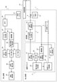
図1は、本発明の実施形態に係る列車制御システムの概略構成を示している。地上装置1は、電文を生成する論理ブロック2と、この論理ブロック2の出力に基づいてATC信号を生成し、増幅して出力する送信機(常用)3と、送信機3の故障時に切り替えて使用される送信機(予備)4とを備えている。地上装置1は、送信機3から軌道回路12へ送信する電文(ATC信号)を、CRC符号の前でフィードバックしてチェック(LD照査)し、送信すべきATC信号と一致するときには送信を継続し、不一致のときには送信を停止するようになっている。
Hereinafter, embodiments of the present invention will be described with reference to the drawings.
FIG. 1 shows a schematic configuration of a train control system according to an embodiment of the present invention. The
列車10が走行する軌道11は、複数の区間1T,2T,3T,…に区画されている。区間1T,2T,3T,…の境界部分は絶縁されており、各境界部分はインピーダンスボンドF1b,F2a,F2b,F3a,…によって結合されている。区間1Tと2Tの境界部分はインピーダンスボンドF1b,F2aによって結合され、区間2Tと3Tの境界部分はインピーダンスボンドF2b,F3aによって結合される。インピーダンスボンドF1b,F2a,F2b,F3a,…は、軌道11に流れる電車電流と軌道信号による信号電流とを振り分ける機能を有する。
The
送信機3から送信されたATC信号は、矢印a1~a6で示すように、送信リレー5、保安器6、ケーブル7、保安器8をそれぞれ介して軌道11の区間2Tに形成される軌道回路12に伝送される。そして、この軌道回路12に伝送されたATC信号が、列車10に搭載された車上装置で受信されて、当該列車10の制御が行われる。送信リレー5を遮断すると、送信機3から軌道回路12への伝送路が切断される。
As shown by arrows a1 to a6, the ATC signal transmitted from the
同様に、予備の送信機4から送信されたATC信号も、送信リレー14、保安器6、ケーブル7、保安器8をそれぞれ介して軌道11の区間2Tに形成される軌道回路12に伝送される。
なお、送信リレー5と接地点間には、送信機3から出力されたATC信号を軌道回路12に印加しないときのダミー抵抗13が接続されている。また、送信リレー14と接地点間には、送信機4から出力されたATC信号を軌道回路12に印加しないときのダミー抵抗15が接続されている。
Similarly, the ATC signal transmitted from the
A
図2は、図1に示した列車制御システムにおける地上装置1と車上装置40の構成例を示しており、要部を抽出して詳細に示している。地上装置1の論理ブロック(論理部)2は、電文作成部21、メモリ部22、復調器23、電文解読部24、電文整合判定部25、送信リレー制御部26及び低下検知部27などを備えている。また、送信機(送信出力部)3は、ATC信号作成部31と信号増幅部32を備えている。
FIG. 2 shows a configuration example of the
電文作成部21で作成された電文は、メモリ部22に供給されて記憶されるとともに、送信機3のATC信号作成部31に供給されてATC信号の作成に用いられる。ATC信号作成部31で作成されたATC信号は、信号増幅部32で増幅され、送信リレー5を介して軌道回路12に出力される。また、信号増幅部32で増幅されたATC信号は、論理ブロック2にフィードバックされる。このATC信号は、復調器23で復調され、電文解読部24で解読された後、メモリ部22に供給されて記憶される。また、信号増幅部32で増幅されたATC信号は、低下検知部27に供給されてレベルの低下が監視される。
The telegram created by the
メモリ部22に記憶された電文、すなわち電文作成部21で作成された電文と電文解読部24で解読されたATC信号(送信信号)は、電文整合判定部25でCRC符号の直前までの整合性が判定される。この電文整合判定部25の判定結果に基づき、送信リレー制御部26により送信リレー5が制御される。
なお、図示を省略したが、予備の送信機4も送信機3と同様な構成になっており、送信機3の故障や誤作動時に切り替えて使用されるようになっている。
The telegram stored in the
Although not shown, the
一方、車上装置40は、受信コイル41、バンドパスフィルタ(BPF)42、レベル判定部43、低下検知部44、復調器45、電文解読照合部46、メモリ部47、タイマ部48、採用電文部49及び速度制御部50などを備えている。受信コイル41で軌道回路12からATC信号(電文)を受信すると、バンドパスフィルタ42に供給されてATC信号以外の周波数成分が除去される。このバンドパスフィルタ42の出力レベルは、レベル判定部43で監視される。低下検知部44でレベルの低下が検知されると、メモリ部47に記憶される。
On the other hand, the on-
また、バンドパスフィルタ42の出力は、復調器45で復調され、電文解読照合部46で解読と照合が実行される。解読及び照合結果はメモリ部47に記憶され、電文受信後、タイマ部48に指定されている時間だけ採用を待つ。タイマ部48に指定されている時間が経過すると、メモリ部47に記憶された出力レベルの低下と、解読及び照合結果が採用電文部49に入力されて電文が採用され、この採用電文部49の出力が速度制御部50に供給されて列車10の速度制御が実行される。
Further, the output of the
図3は、共通予備方式(N+2)の地上装置1の構成例を示すブロック図である。この地上装置1は、1系論理部2aと2系論理部2bを備えており、これら1系論理部2aと2系論理部2bに対して、共通の送信出力部3a,3b及び予備の送信出力部4a,4bが設けられている。1系論理部2aには受信入力部9a-1~9a-10、2系論理部2bには受信入力部9b-1~9b-10がそれぞれ設けられている。すなわち、送信出力部が10トラックに対して、予備が2台で合計12台設けられており、10軌道対応の構成である。
なお、図3において、1TSCR,2TSCR,SCR_S1,SCR_S2は送信リレー(SCRリレー)であり、DLはダミー抵抗である。
FIG. 3 is a block diagram showing a configuration example of the
In FIG. 3, 1TSCR, 2TSCR, SCR_S1 and SCR_S2 are transmission relays (SCR relays), and DL is a dummy resistor.
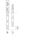
図4は、送信機3から出力されるATC信号の電文構成(1フレーム)の一例を示す模式図である。本例では、9ビットのスタートフラグの後に、6ビットのデータと1ビットのフラグが交互に繰り返されており、最後にCRC符号が付加されている。軌道回路ID(15bit)は、(1)線区コード(2bit)、(2)区間コード(6bit)及び(3)軌道回路コード(7bit)で表される。また、(4)経路コード(5bit)と(5)開通区間数(5bit)が含まれている。これらのデータがスタートフラグに続いて伝送される。
FIG. 4 is a schematic diagram showing an example of a telegram configuration (1 frame) of an ATC signal output from the
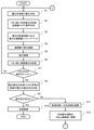
次に、上記のような構成の列車制御システムにおいて、図5乃至図7のフローチャートと、図8及び図9の模式図により動作を説明する。図5及び図6は、地上装置の動作について説明するためのフローチャートである。まず、論理ブロック2の電文作成部21で電文を作成する(ステップS1)。作成した電文は、メモリ部22に供給して記憶するとともに、送信機3のATC信号作成部31に供給してATC信号を作成し、このATC信号を信号増幅部32で増幅する(ステップS2)。信号増幅部32で増幅したATC信号は、送信リレー5を介して軌道回路12に出力するとともに、フィードバックチェック(LD照査)のために復調器23に入力する(ステップS3)。
Next, in the train control system having the above configuration, the operation will be described with reference to the flowcharts of FIGS. 5 to 7 and the schematic views of FIGS. 8 and 9. 5 and 6 are flowcharts for explaining the operation of the ground equipment. First, the
次に、ATC信号を復調器23で復調し(ステップS4)、電文解読部24で解読した後(ステップS5)、解読したATC信号をメモリ部22に記憶する(ステップS6)。そして、電文整合判定部25でCRC符号の直前のビットか否か判定し(ステップS7)、そうであればCRC符号の直前のビットまで電文の整合性をチェックする(ステップS8)。続いて、整合性があるか否か判定し(ステップS9)、整合性がある場合には送信を継続する(ステップS10)。
ステップS7で直前のビットでないと判定された場合には、CRC符号の直前のビットになるまでステップS1~S6の動作を繰り返す。
Next, the ATC signal is demodulated by the demodulator 23 (step S4), decoded by the message decoding unit 24 (step S5), and then the decoded ATC signal is stored in the memory unit 22 (step S6). Then, the message matching
If it is determined in step S7 that the bit is not the immediately preceding bit, the operations of steps S1 to S6 are repeated until the bit immediately preceding the CRC code is reached.
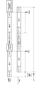
ステップS9で整合性がないと判定、すなわち誤りを検出したときには、送信機3から軌道回路12への伝送路を遮断する(ステップS11)。具体的には、送信リレー5をオフさせるか、送信機3の出力を停止させてATC信号を1フレーム送信する前に停止させる(図8参照)。その後、伝送路の遮断を所定時間、例えば300ms継続してから復帰させる(ステップS12)。
When it is determined in step S9 that there is no consistency, that is, when an error is detected, the transmission path from the
次に、図9に示すように、地上装置1側と車上装置40側で同期を取るための同期ビットを付けた後、電文2を再送する。再送用の電文2は、電文1と同じもので、論理ブロック2の電文作成部21で作成する(ステップS13)。この再送用の電文2は、必ずしも電文1と同じ必要はなく、再送用の電文を送るのと同じタイミングで電文作成部21にある最新の電文を採用しても良い。作成した電文は、メモリ部22に供給して記憶するとともに、送信機3のATC信号作成部31に供給してATC信号を作成し、このATC信号を信号増幅部32で増幅する(ステップS14)。信号増幅部32で増幅したATC信号は、送信リレー5を介して軌道回路12に出力するとともに、フィードバックチェックのために復調器23に入力する(ステップS15)。
Next, as shown in FIG. 9, the
次に、ATC信号を復調器23で復調し(ステップS16)、電文解読部24で解読した後(ステップS17)、解読したATC信号をメモリ部22に記憶する(ステップS18)。そして、電文整合判定部25でCRC符号の直前のビットか否か判定し(ステップS19)、そうであればCRC符号の直前のビットまで電文の整合性をチェックする(ステップS20)。続いて、整合性があるか否か判定し(ステップS21)、整合性がある場合には送信を継続する(ステップS22)。
ステップS19で直前のビットでないと判定された場合には、CRC符号の直前のビットになるまでステップS13~S18の動作を繰り返す。
Next, the ATC signal is demodulated by the demodulator 23 (step S16), decoded by the message decoding unit 24 (step S17), and then the decoded ATC signal is stored in the memory unit 22 (step S18). Then, the message matching
If it is determined in step S19 that the bit is not the immediately preceding bit, the operations of steps S13 to S18 are repeated until the bit immediately preceding the CRC code is reached.
ステップS21で整合性がないと判定されたときには、重大なエラーがあるので予備の送信機4に切り替え(ステップS23)、ステップS1に戻って予備の送信機4で同様な電文作成動作を行う。
上述したように、電文2もスタートフラグからCRCの直前まで受信した時点で送信信号と比較し、1ビットでもエラーがあった場合は送信機3を予備の送信機4に切り替える。1ビットだけのエラーは、一過性のノイズなどでもありえるので、常用の送信機3の送信を一度停止させるが、再度常用の送信機3を稼動させることとする。これにより、一過性のノイズなどにより1ビットだけのエラーとなった場合には、予備の送信機4に切り替わらずに常用の送信機3で稼動を続けることが出来る。
When it is determined in step S21 that there is no consistency, there is a serious error, so the switch is switched to the spare transmitter 4 (step S23), and the process returns to step S1 to perform the same message creation operation on the
As described above, the
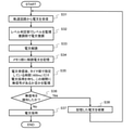
図7は、車上装置40の動作について説明するためのフローチャートである。車上装置40は、受信コイル41で軌道回路12から電文(ATC信号)を受信すると(ステップS31)、バンドパスフィルタ42に供給してATC信号以外の周波数成分を除去し、レベル判定部43でバンドパスフィルタ42の出力レベルを監視するとともに、復調器45で電文を復調する(ステップS32)。レベルの低下が低下検知部44で検知されると、メモリ部47にレベル低下を検知したことを記憶する。また、復調器45で復調した電文を電文解読照合部46で解読し(ステップS33)、メモリ部47に解読した電文を記憶する(ステップS34)。
FIG. 7 is a flowchart for explaining the operation of the on-
電文受信後、タイマ部48で指定している時間(例えば400ms)だけ電文の採用を待ち、この期間に無信号があるか否かを監視する(ステップS35)。そして、無信号を検知したか否か判定し(ステップS36)、無信号を検知しない場合には電文を採用し(ステップS37)、無信号を検知した場合にはエラーが含まれているので、メモリ部47に記憶した電文を破棄する(ステップS38)。ステップS35においては、無信号があるか否かを監視する例を示したが、地上装置1側では、車上装置40側で無信号を検知できる所定時間(例えば300ms)の無信号期間を設定することで、送信中の信号の影響を受け難くでき、より確実な監視が可能となる。そして、ステップS31に戻って、軌道回路12から次の電文を受信する。
After receiving the telegram, the
本発明によれば、地上装置1側の送信電文を全て(1フレーム)送信する前に、CRC符号の直前で、地上装置1側から送信している信号のフィードバックチェックを行い、フレームのスタートフラグからCRC符号の直前まで受信した時点で送信信号と比較し、1ビットでもエラーがあった場合には送信リレー5を300ms間遮断させる(論理ブロック2から送信機3間のデータ伝送も停止指示)。これにより、地上装置1側からエラー電文(誤った電文)が送信されるのを抑制し、車上装置40側で誤った電文が採用される確率を低減することができる。また、CRC符号の直前で、電文内容の整合性を確認することにより、CRC検定をすり抜ける恐れがある2ビット以上誤った電文の送信を1フレーム全て送る前に停止させることが可能である。従って、ノンフェールセーフな送信機3を用いることができ、コストの増大や機器の複雑化を招くことなく送信機でATC信号を作成して送信することができる。
According to the present invention, before transmitting all the transmission messages on the
更に、車上装置40側ではCRC検定を行うので、電文を地上装置1と車上装置40で二重チェックすることができる。しかも、誤りを検出したときには、送信機3から軌道回路12への伝送路を遮断して待機させ、無信号状態の期間を検知したときに、車上装置40側で受信した電文を破棄することで、軌道回路12の接続区間で、列車10が隣接する軌道回路間を跨いでいるときの電文連結による誤作動の可能性も回避できる。よって、車上装置40側で複数電文照合を採用する必要がなく、1電文をデジタル伝送して列車10の制御を高速に行うことができる。しかも、エラーが発生した場合には、電文を再伝送し、CRC検定で再度エラーを検出した場合には、予備の送信機4に切り替えることで、誤った電文の伝送をより低減できる。
Further, since the CRC test is performed on the on-
以上の実施形態で説明された回路構成や動作手順等については、本発明が理解・実施できる程度に概略的に示したものに過ぎない。従って本発明は、説明された実施形態に限定されるものではなく、特許請求の範囲に示される技術的思想の範囲を逸脱しない限り様々な形態に変更することができる。 The circuit configuration, operating procedure, and the like described in the above embodiments are merely schematically shown to the extent that the present invention can be understood and implemented. Therefore, the present invention is not limited to the described embodiment, and can be changed to various embodiments as long as it does not deviate from the scope of the technical idea shown in the claims.
1…地上装置、2…論理ブロック、3…送信機(常用)、4…送信機(予備)、5,14…送信リレー、6,8…保安器、7…ケーブル、10…列車、11…軌道、12…軌道回路、13,15…ダミー抵抗、21…電文作成部、22,47…メモリ部、23,45…復調器、24…電文解読部、25…電文整合判定部、26…送信リレー制御部、27,44…低下検知部、31…ATC信号作成部、32…信号増幅部、40…車上装置、41…受信コイル、42…バンドパスフィルタ、43…レベル判定部、46…電文解読照合部、48…タイマ部、49…採用電文部、50…速度制御部 1 ... Ground equipment, 2 ... Logic block, 3 ... Transmitter (regular), 4 ... Transmitter (spare), 5, 14 ... Transmission relay, 6, 8 ... Protective device, 7 ... Cable, 10 ... Train, 11 ... Track, 12 ... Track circuit, 13, 15 ... Dummy resistance, 21 ... Message creation unit, 22, 47 ... Memory unit, 23, 45 ... Relay, 24 ... Message decoding unit, 25 ... Message matching determination unit, 26 ... Transmission Relay control unit, 27, 44 ... drop detection unit, 31 ... ATC signal creation unit, 32 ... signal amplification unit, 40 ... on-board device, 41 ... receiver coil, 42 ... bandpass filter, 43 ... level determination unit, 46 ... Message decoding collation unit, 48 ... Timer unit, 49 ... Adopted message unit, 50 ... Speed control unit
Claims (5)
前記地上装置は、電文を作成し、CRC符号を付加した送信信号を伝送路経由で軌道回路へ送信し、作成した電文と前記送信信号中の電文が不一致の場合、前記伝送路を一時的に遮断し、所定時間待機後に前記送信信号を再伝送し、当該送信信号の誤りを検出したときには予備の送信機に切り替え、
前記車上装置は、前記軌道回路上の無信号を検出した場合に、受信した直前の電文を破棄する、列車制御システム。 A train control system that digitally transmits telegrams between ground equipment and on-board equipment to control trains.
The ground device creates a message, transmits a transmission signal to which a CRC code is added to an orbital circuit via a transmission line, and if the created message and the message in the transmission signal do not match, the transmission line is temporarily used. It shuts off, waits for a predetermined time, retransmits the transmission signal, and when an error in the transmission signal is detected, switches to a spare transmitter.
The on-board device is a train control system that discards a telegram immediately before being received when a no signal on the track circuit is detected.
Priority Applications (1)
| Application Number | Priority Date | Filing Date | Title |
|---|---|---|---|
| JP2017173430A JP6991803B2 (en) | 2017-09-08 | 2017-09-08 | Train control system |
Applications Claiming Priority (1)
| Application Number | Priority Date | Filing Date | Title |
|---|---|---|---|
| JP2017173430A JP6991803B2 (en) | 2017-09-08 | 2017-09-08 | Train control system |
Publications (2)
| Publication Number | Publication Date |
|---|---|
| JP2019048542A JP2019048542A (en) | 2019-03-28 |
| JP6991803B2 true JP6991803B2 (en) | 2022-01-13 |
Family
ID=65905327
Family Applications (1)
| Application Number | Title | Priority Date | Filing Date |
|---|---|---|---|
| JP2017173430A Active JP6991803B2 (en) | 2017-09-08 | 2017-09-08 | Train control system |
Country Status (1)
| Country | Link |
|---|---|
| JP (1) | JP6991803B2 (en) |
Citations (3)
| Publication number | Priority date | Publication date | Assignee | Title |
|---|---|---|---|---|
| JP2000252965A (en) | 1999-02-25 | 2000-09-14 | Nippon Signal Co Ltd:The | Transmission system for digital communication |
| JP2003011821A (en) | 2001-06-27 | 2003-01-15 | Nippon Signal Co Ltd:The | Digital transmission type automatic train control device |
| JP2011146965A (en) | 2010-01-15 | 2011-07-28 | Railway Technical Research Institute | Telegram message transmitting apparatus and method |
-
2017
- 2017-09-08 JP JP2017173430A patent/JP6991803B2/en active Active
Patent Citations (3)
| Publication number | Priority date | Publication date | Assignee | Title |
|---|---|---|---|---|
| JP2000252965A (en) | 1999-02-25 | 2000-09-14 | Nippon Signal Co Ltd:The | Transmission system for digital communication |
| JP2003011821A (en) | 2001-06-27 | 2003-01-15 | Nippon Signal Co Ltd:The | Digital transmission type automatic train control device |
| JP2011146965A (en) | 2010-01-15 | 2011-07-28 | Railway Technical Research Institute | Telegram message transmitting apparatus and method |
Also Published As
| Publication number | Publication date |
|---|---|
| JP2019048542A (en) | 2019-03-28 |
Similar Documents
| Publication | Publication Date | Title |
|---|---|---|
| EP0878373B1 (en) | Train detection system | |
| CA2997979C (en) | Warm or hot standby track card module for use on a wayside of a railway system | |
| CA2916001C (en) | Track circuit mechanical joint integrity checker | |
| JP6991803B2 (en) | Train control system | |
| JP3834827B2 (en) | Railway information transmission system | |
| JP2015159700A (en) | Train radio system | |
| JP6270504B2 (en) | Train radio system | |
| CN102983919A (en) | Detection method of transponder transport module and detection device thereof | |
| JP2011146965A (en) | Telegram message transmitting apparatus and method | |
| EP3381762B1 (en) | System and method for detecting the presence of a train on a railway track | |
| KR102094256B1 (en) | Track circuit for various/multiple information telegram transmission and control method thereof | |
| US20180093684A1 (en) | Wayside communication system using power grid lines | |
| CN110214108B (en) | Method for transmitting messages and railway component | |
| US10527660B2 (en) | Method, controller and system for detecting a leakage of a track signal on at least one railway track | |
| KR100354973B1 (en) | Method and system for transmitting railroad information | |
| JP4968958B2 (en) | Train control device | |
| JP6964460B2 (en) | Transmitter, train control information transmission system, and train control information transmission method | |
| JP6830407B2 (en) | Vehicle control device | |
| JP2014072569A (en) | Telegraphic message control communication device | |
| JPH11112360A (en) | Information transmission equipment for railway vehicles | |
| HK1176335A1 (en) | Onboard transponder device and method of confirming soundness thereof |
Legal Events
| Date | Code | Title | Description |
|---|---|---|---|
| A621 | Written request for application examination |
Free format text: JAPANESE INTERMEDIATE CODE: A621 Effective date: 20200617 |
|
| A977 | Report on retrieval |
Free format text: JAPANESE INTERMEDIATE CODE: A971007 Effective date: 20210423 |
|
| A131 | Notification of reasons for refusal |
Free format text: JAPANESE INTERMEDIATE CODE: A131 Effective date: 20210511 |
|
| A521 | Request for written amendment filed |
Free format text: JAPANESE INTERMEDIATE CODE: A523 Effective date: 20210712 |
|
| A131 | Notification of reasons for refusal |
Free format text: JAPANESE INTERMEDIATE CODE: A131 Effective date: 20210817 |
|
| A521 | Request for written amendment filed |
Free format text: JAPANESE INTERMEDIATE CODE: A523 Effective date: 20211018 |
|
| TRDD | Decision of grant or rejection written | ||
| A01 | Written decision to grant a patent or to grant a registration (utility model) |
Free format text: JAPANESE INTERMEDIATE CODE: A01 Effective date: 20211130 |
|
| A61 | First payment of annual fees (during grant procedure) |
Free format text: JAPANESE INTERMEDIATE CODE: A61 Effective date: 20211208 |
|
| R150 | Certificate of patent or registration of utility model |
Ref document number: 6991803 Country of ref document: JP Free format text: JAPANESE INTERMEDIATE CODE: R150 |
|
| R250 | Receipt of annual fees |
Free format text: JAPANESE INTERMEDIATE CODE: R250 |
|
| R250 | Receipt of annual fees |
Free format text: JAPANESE INTERMEDIATE CODE: R250 |