JP6991925B2 - Blower fan - Google Patents
Blower fan Download PDFInfo
- Publication number
- JP6991925B2 JP6991925B2 JP2018102526A JP2018102526A JP6991925B2 JP 6991925 B2 JP6991925 B2 JP 6991925B2 JP 2018102526 A JP2018102526 A JP 2018102526A JP 2018102526 A JP2018102526 A JP 2018102526A JP 6991925 B2 JP6991925 B2 JP 6991925B2
- Authority
- JP
- Japan
- Prior art keywords
- washer
- impeller
- blower fan
- shape
- vibration
- Prior art date
- Legal status (The legal status is an assumption and is not a legal conclusion. Google has not performed a legal analysis and makes no representation as to the accuracy of the status listed.)
- Active
Links
Images


Classifications
-
- F—MECHANICAL ENGINEERING; LIGHTING; HEATING; WEAPONS; BLASTING
- F04—POSITIVE - DISPLACEMENT MACHINES FOR LIQUIDS; PUMPS FOR LIQUIDS OR ELASTIC FLUIDS
- F04D—NON-POSITIVE-DISPLACEMENT PUMPS
- F04D29/00—Details, component parts, or accessories
- F04D29/26—Rotors specially for elastic fluids
- F04D29/263—Rotors specially for elastic fluids mounting fan or blower rotors on shafts
-
- F—MECHANICAL ENGINEERING; LIGHTING; HEATING; WEAPONS; BLASTING
- F04—POSITIVE - DISPLACEMENT MACHINES FOR LIQUIDS; PUMPS FOR LIQUIDS OR ELASTIC FLUIDS
- F04D—NON-POSITIVE-DISPLACEMENT PUMPS
- F04D17/00—Radial-flow pumps, e.g. centrifugal pumps; Helico-centrifugal pumps
- F04D17/08—Centrifugal pumps
-
- F—MECHANICAL ENGINEERING; LIGHTING; HEATING; WEAPONS; BLASTING
- F04—POSITIVE - DISPLACEMENT MACHINES FOR LIQUIDS; PUMPS FOR LIQUIDS OR ELASTIC FLUIDS
- F04D—NON-POSITIVE-DISPLACEMENT PUMPS
- F04D25/00—Pumping installations or systems
- F04D25/02—Units comprising pumps and their driving means
- F04D25/06—Units comprising pumps and their driving means the pump being electrically driven
-
- F—MECHANICAL ENGINEERING; LIGHTING; HEATING; WEAPONS; BLASTING
- F04—POSITIVE - DISPLACEMENT MACHINES FOR LIQUIDS; PUMPS FOR LIQUIDS OR ELASTIC FLUIDS
- F04D—NON-POSITIVE-DISPLACEMENT PUMPS
- F04D25/00—Pumping installations or systems
- F04D25/02—Units comprising pumps and their driving means
- F04D25/08—Units comprising pumps and their driving means the working fluid being air, e.g. for ventilation
-
- F—MECHANICAL ENGINEERING; LIGHTING; HEATING; WEAPONS; BLASTING
- F04—POSITIVE - DISPLACEMENT MACHINES FOR LIQUIDS; PUMPS FOR LIQUIDS OR ELASTIC FLUIDS
- F04D—NON-POSITIVE-DISPLACEMENT PUMPS
- F04D29/00—Details, component parts, or accessories
- F04D29/26—Rotors specially for elastic fluids
- F04D29/28—Rotors specially for elastic fluids for centrifugal or helico-centrifugal pumps for radial-flow or helico-centrifugal pumps
- F04D29/281—Rotors specially for elastic fluids for centrifugal or helico-centrifugal pumps for radial-flow or helico-centrifugal pumps for fans or blowers
-
- F—MECHANICAL ENGINEERING; LIGHTING; HEATING; WEAPONS; BLASTING
- F04—POSITIVE - DISPLACEMENT MACHINES FOR LIQUIDS; PUMPS FOR LIQUIDS OR ELASTIC FLUIDS
- F04D—NON-POSITIVE-DISPLACEMENT PUMPS
- F04D29/00—Details, component parts, or accessories
- F04D29/66—Combating cavitation, whirls, noise, vibration or the like; Balancing
- F04D29/661—Combating cavitation, whirls, noise, vibration or the like; Balancing especially adapted for elastic fluid pumps
- F04D29/668—Combating cavitation, whirls, noise, vibration or the like; Balancing especially adapted for elastic fluid pumps damping or preventing mechanical vibrations
-
- F—MECHANICAL ENGINEERING; LIGHTING; HEATING; WEAPONS; BLASTING
- F04—POSITIVE - DISPLACEMENT MACHINES FOR LIQUIDS; PUMPS FOR LIQUIDS OR ELASTIC FLUIDS
- F04D—NON-POSITIVE-DISPLACEMENT PUMPS
- F04D29/00—Details, component parts, or accessories
- F04D29/18—Rotors
- F04D29/20—Mounting rotors on shafts
Landscapes
- Engineering & Computer Science (AREA)
- Mechanical Engineering (AREA)
- General Engineering & Computer Science (AREA)
- Structures Of Non-Positive Displacement Pumps (AREA)
Description
本発明は、モーターの回転軸に取り付けられた羽根車を回転させることによって、空気を送風する送風ファンに関する。 The present invention relates to a blower fan that blows air by rotating an impeller attached to a rotating shaft of a motor.
モーターで羽根車を回転させて送風する送風ファンには様々なタイプが知られており、何れの送風ファンも広く使用されている。これらの送風ファンでは、羽根車が回転する中心軸上に取付穴が貫通されており、この取付穴に、先端側にネジなどが形成されたモーターの回転軸を挿通させて,取付穴から突出した回転軸に、ナットなどを用いて羽根車が取り付けられている。このような方法で羽根車を取り付ければ、羽根車の取付穴の内径をモーターの回転軸に対して適切な寸法に形成しておくことによって、モーターの回転軸と羽根車とを容易に芯出しした状態で、簡単に羽根車を取り付けることが可能となる。 Various types of blower fans are known for blowing air by rotating an impeller with a motor, and all types of blower fans are widely used. In these blower fans, a mounting hole is penetrated on the central shaft on which the impeller rotates, and the rotating shaft of the motor with a screw or the like formed on the tip side is inserted through this mounting hole and protrudes from the mounting hole. An impeller is attached to the rotating shaft using a nut or the like. If the impeller is mounted in this way, the inner diameter of the mounting hole of the impeller is formed to an appropriate dimension with respect to the rotating shaft of the motor, so that the rotating shaft of the motor and the impeller can be easily centered. It is possible to easily attach the impeller in this state.
もっとも、この方法では、モーターの回転軸と羽根車とが直接に(あるいはナットなどを介して間接的に)固体接触することになるので、回転時にモーターで生じる振動が羽根車に伝わって、騒音を発生させるという問題がある。ここで、回転時にモーターで生じる振動には、モーターの回転軸が軸方向に細かく進退動する振動(以下、軸方向振動と呼ぶ)と、回転軸が一回転する間にモーターのトルクが細かく変動する振動(以下、回転方向振動と呼ぶ)とが存在する。このうちの軸方向振動に対しては、羽根車が前後からゴム製のワッシャで挟持された状態で、モーターの回転軸に羽根車を取り付ける方法が提案されている(特許文献1)。 However, in this method, the rotating shaft of the motor and the impeller come into direct solid contact (or indirectly via a nut or the like), so the vibration generated by the motor during rotation is transmitted to the impeller and makes noise. There is a problem of generating. Here, the vibration generated by the motor during rotation includes vibration in which the rotation axis of the motor moves back and forth finely in the axial direction (hereinafter referred to as axial vibration) and torque of the motor finely fluctuates during one rotation of the rotation shaft. There is vibration (hereinafter referred to as rotational vibration). For the axial vibration, a method has been proposed in which the impeller is attached to the rotating shaft of the motor while the impeller is sandwiched between front and rear rubber washers (Patent Document 1).
また、軸方向振動および回転方向振動を同時に対策可能な方法としては、羽根車の取付穴とモーターの回転軸との間に防振用部材を介在させる方法も提案されている(特許文献2)。この方法で用いられる防振用部材は、金属製の内筒と、同じく金属製の外筒との間にゴム材料が充填された構造となっている。内筒の中心軸上には取付穴が貫通すると共に、外筒は断面が多角形形状に形成されており、防振用部材の外形形状は、多角柱の中心軸上に取付穴が貫通した形状となっている。また、羽根車の中心軸上には、防振用部材と同じ多角形形状の取付穴が貫通しており、取付穴には防振用部材が圧入されている。そして、この防振用部材の取付穴にモーターの回転軸を挿通させて、取付穴から突出させた回転軸の先端にナットなどを取り付けることによって、モーターの回転軸に羽根車を取り付ける。この提案の方法では、防振用部材の内筒とモーターの回転軸、および防振用部材の外筒と羽根車とは固体接触するものの、防振用部材の内筒と外筒との間にはゴム材料が介在しているので、モーターの軸方向振動や回転方向振動が羽根車に伝わることを防止することが可能となる。 Further, as a method capable of simultaneously taking measures against axial vibration and rotational vibration, a method of interposing a vibration isolator member between the mounting hole of the impeller and the rotating shaft of the motor has been proposed (Patent Document 2). .. The anti-vibration member used in this method has a structure in which a rubber material is filled between a metal inner cylinder and a metal outer cylinder. A mounting hole penetrates on the central axis of the inner cylinder, and the outer cylinder has a polygonal cross section. It has a shape. Further, a mounting hole having the same polygonal shape as the vibration-proofing member penetrates on the central axis of the impeller, and the vibration-proofing member is press-fitted into the mounting hole. Then, the impeller is attached to the rotating shaft of the motor by inserting the rotating shaft of the motor into the mounting hole of the vibration isolator and attaching a nut or the like to the tip of the rotating shaft protruding from the mounting hole. In the proposed method, the inner cylinder of the anti-vibration member and the rotating shaft of the motor, and the outer cylinder of the anti-vibration member and the impeller make solid contact, but between the inner cylinder and the outer cylinder of the anti-vibration member. Since the rubber material is interposed in the motor, it is possible to prevent the axial vibration and the rotational vibration of the motor from being transmitted to the impeller.
しかし、上述した従来の何れの技術を用いた場合でも、依然として送風ファンの騒音を十分には低減させることができないという問題があった。すなわち、上述した特許文献1の技術では、モーターの軸方向振動が羽根車に伝わることは抑制できるが、モーターの回転方向振動が羽根車に伝わってしまうため、送風ファンの騒音を十分に低減させることは困難である。また、上述した特許文献2の技術では、外筒と内筒との間にゴム材料を充填して形成された厚いゴム層が存在するため、モーターの回転軸と羽根車の中心軸とがずれた状態(いわゆる、芯ずれ状態)となり易く、芯ずれ状態が発生すると、防振用部材を用いたことで却って騒音が大きくなってしまう。このような理由から、従来の技術では、依然として送風ファンの騒音を十分には低減させることが困難であった。 However, even if any of the above-mentioned conventional techniques is used, there is still a problem that the noise of the blower fan cannot be sufficiently reduced. That is, in the above-mentioned technique of Patent Document 1, the axial vibration of the motor can be suppressed from being transmitted to the impeller, but the rotational vibration of the motor is transmitted to the impeller, so that the noise of the blower fan is sufficiently reduced. That is difficult. Further, in the technique of Patent Document 2 described above, since there is a thick rubber layer formed by filling a rubber material between the outer cylinder and the inner cylinder, the rotation axis of the motor and the central axis of the impeller deviate from each other. It tends to be in a misaligned state (so-called misaligned state), and when a misaligned state occurs, the noise becomes louder due to the use of the anti-vibration member. For this reason, it is still difficult to sufficiently reduce the noise of the blower fan with the conventional technique.
この発明は、従来の技術が有する上述した課題に対応してなされたものであり、羽根車をモーターの回転軸に簡単に取り付けることが可能で、尚且つ、騒音も低減させることが可能な送風ファンの提供を目的とする。 The present invention has been made in response to the above-mentioned problems of the prior art, and the impeller can be easily attached to the rotating shaft of the motor, and the noise can be reduced. The purpose is to provide fans.
上述した課題を解決するために本発明の送風ファンは次の構成を採用した。すなわち、
中心軸上に取付穴が貫通した羽根車と、前記取付穴に回転軸が挿通されたモーターと、前記取付穴から突出した前記回転軸が挿通されるワッシャと、前記ワッシャを介して前記羽根車を押圧した状態で前記回転軸に取り付けられることによって、前記羽根車を前記回転軸に取り付ける取付部材とを備え、前記モーターを用いて前記羽根車を回転させることによって送風する送風ファンにおいて、
前記ワッシャは、前記回転軸が挿通される挿通穴を中心とする円形形状から円周方向の複数箇所が半径方向に膨出し、且つ、前記複数箇所の間には前記円形形状から膨出していない箇所が残存した特定形状の板状部材であり、
前記ワッシャと前記羽根車との間には、弾性材料によって形成された防振部材が介在されており、
前記防振部材の形状は、前記ワッシャよりも大きな前記特定形状で、上面側には前記ワッシャが嵌め込まれる前記特定形状の第1凹部が形成されており、
前記羽根車の上面には、前記防振部材が嵌め込まれる前記特定形状の第2凹部が形成されている
ことを特徴とする。
In order to solve the above-mentioned problems, the blower fan of the present invention adopts the following configuration. That is,
An impeller with a mounting hole penetrating on the central shaft, a motor with a rotating shaft inserted through the mounting hole, a washer through which the rotating shaft protruding from the mounting hole is inserted, and the impeller via the washer. In a blower fan, which is provided with a mounting member for attaching the impeller to the rotating shaft by being attached to the rotating shaft in a pressed state, and blows air by rotating the impeller using the motor.
The washer has a plurality of points in the circumferential direction bulging in the radial direction from a circular shape centered on an insertion hole through which the rotation axis is inserted , and bulging from the circular shape between the plurality of places. It is a plate-shaped member with a specific shape that has not been left .
A vibration-proof member formed of an elastic material is interposed between the washer and the impeller.
The shape of the anti-vibration member is the specific shape larger than the washer, and the first recess of the specific shape into which the washer is fitted is formed on the upper surface side.
The upper surface of the impeller is characterized in that a second recess having the specific shape into which the anti-vibration member is fitted is formed.
かかる本発明の送風ファンにおいては、羽根車は防振部材とワッシャとを介して取付部材によって、モーターの回転軸に取り付けられている。ここで、ワッシャには、モーターの回転軸が挿通される挿通穴が中心に形成されていると共に、ワッシャの形状は、挿通穴を中心とする円形形状から円周方向の複数箇所が半径方向に膨出し、且つ、それら複数箇所の間には円形形状から膨出していない箇所が残存した特定形状に形成されている。また、防振部材はゴム材料や樹脂材料などの弾性材料によって形成されていると共に、防振部材の形状は、ワッシャよりも大きな特定形状で、上面側にはワッシャが嵌め込まれる特定形状の第1凹部が形成されている。更に、羽根車の上面には、防振部材が嵌め込まれる特定形状の第2凹部が形成されている。 In the blower fan of the present invention, the impeller is attached to the rotating shaft of the motor by an attachment member via a vibration isolator member and a washer. Here, the washer is formed at the center of an insertion hole through which the rotation shaft of the motor is inserted, and the shape of the washer is such that a plurality of points in the circumferential direction are radial from a circular shape centered on the insertion hole. It is formed in a specific shape in which a portion that does not bulge from a circular shape remains between the plurality of bulges . Further, the anti-vibration member is formed of an elastic material such as a rubber material or a resin material, and the shape of the anti-vibration member is a specific shape larger than the washer, and the first specific shape in which the washer is fitted on the upper surface side. A recess is formed. Further, a second recess having a specific shape into which the anti-vibration member is fitted is formed on the upper surface of the impeller.
このため、モーターの回転軸に羽根車を取り付けると、羽根車の第2凹部に防振部材が嵌め込まれ、防振部材の第1凹部にワッシャが嵌め込まれた状態となり、羽根車とワッシャとの間には、モーターの軸方向および回転方向の何れについても防振部材が介在することとなる。その結果、モーターの軸方向振動および回転方向振動の何れも、羽根車に伝わることを抑制することができるので、送風ファンの騒音を低減することが可能となる。それでいながら、防振部材およびワッシャを介して、取付部材で羽根車を取り付けることができるので、モーターの回転軸と羽根車とを芯出しした状態で、羽根車をモーターの回転軸に、簡単に取り付けることが可能となる。 Therefore, when the impeller is attached to the rotating shaft of the motor, the anti-vibration member is fitted into the second recess of the impeller, and the washer is fitted into the first recess of the anti-vibration member. A vibration isolator is interposed between the motors in both the axial direction and the rotational direction. As a result, both the axial vibration and the rotational vibration of the motor can be suppressed from being transmitted to the impeller, so that the noise of the blower fan can be reduced. Nevertheless, the impeller can be attached with the mounting member via the anti-vibration member and washer, so it is easy to use the impeller as the rotating shaft of the motor with the rotating shaft of the motor and the impeller centered. It can be attached to.
また、上述した本発明の送風ファンにおいては、ワッシャの形状を、挿通穴の半径の2.5倍よりも大きな半径の円周から、複数箇所を半径方向に膨出させた特定形状としても良い。 Further, in the blower fan of the present invention described above, the shape of the washer may be a specific shape in which a plurality of points are bulged in the radial direction from a circumference having a radius larger than 2.5 times the radius of the insertion hole. ..
こうすれば、特定形状のワッシャが防振部材に当接する周長が長くなるので、モーターの回転トルクを伝える際に、ワッシャが防振部材を圧縮する面積も大きくなる。その結果、大きな回転トルクを伝えることが可能となり、また、防振部材が受ける応力が小さくなるので、モーターでより大きな回転方向振動が発生しても、防振部材で吸収することが可能となる。 By doing so, the peripheral length of the washer having a specific shape in contact with the anti-vibration member becomes long, so that the area where the washer compresses the anti-vibration member when transmitting the rotational torque of the motor also becomes large. As a result, it is possible to transmit a large rotational torque, and the stress applied to the vibration isolator is reduced, so that even if a larger rotational vibration is generated by the motor, the vibration isolator can absorb it. ..
また、上述した本発明の送風ファンにおいては、モーターの回転軸に羽根車を取り付ける際には、ゴム材料で形成された底面側ワッシャを羽根車の底面側に設けることによって、羽根車の上面側に設けられた防振部材と底面側ワッシャとで、羽根車を挟持した状態で取り付けるようにしても良い。 Further, in the blower fan of the present invention described above, when the impeller is attached to the rotating shaft of the motor, a bottom side washer made of a rubber material is provided on the bottom surface side of the impeller so that the upper surface side of the impeller is provided. The impeller may be attached while the impeller is sandwiched between the anti-vibration member and the washer on the bottom side.
こうすれば、モーターの軸方向振動が羽根車に伝わることをより確実に防止することができるので、送風ファンの騒音を更に低減させることが可能となる。 By doing so, it is possible to more reliably prevent the axial vibration of the motor from being transmitted to the impeller, and it is possible to further reduce the noise of the blower fan.
また、上述した本発明の送風ファンにおいては、ワッシャを多角形形状に形成してもよい。 Further, in the blower fan of the present invention described above, the washer may be formed into a polygonal shape.
こうすれば、モーターの回転に伴ってワッシャが回転しようとした時に、多角形状形状の角の部分で防振部材を強く押すことができるので、モーターの回転トルクを確実に防振部材に伝えることができ、その結果、大きな回転トルクを羽根車に伝えることが可能となる。 By doing so, when the washer tries to rotate with the rotation of the motor, the anti-vibration member can be strongly pushed by the corners of the polygonal shape, so that the rotational torque of the motor is surely transmitted to the anti-vibration member. As a result, it becomes possible to transmit a large rotational torque to the impeller.
また、上述した本発明の送風ファンにおいては、ワッシャを楕円形状あるいは小判形状に形成してもよい。 Further, in the blower fan of the present invention described above, the washer may be formed into an elliptical shape or an oval shape.
こうすれば、モーターの回転に伴ってワッシャが回転しようとした時に、ワッシャが局所的に防振部材を強い力で押す箇所が生じない。このため、長い間に亘る使用によっても、ゴム材料で形成された防振部材が局所的に劣化する事態を防止することが可能となる。 In this way, when the washer tries to rotate with the rotation of the motor, there is no place where the washer locally pushes the vibration isolator with a strong force. Therefore, it is possible to prevent a situation in which the anti-vibration member made of the rubber material is locally deteriorated even after long-term use.
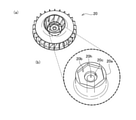
図1は、本実施例の送風ファン1の構造を示す斜視図である。図1(a)に示されるように、本実施例の送風ファン1は、本体ケース10の内部に羽根車20が収容され、本体ケース10の外側にモーター30が取り付けられており、本体ケース10内の羽根車20を、モーター30によって回転させる構造となっている。
FIG. 1 is a perspective view showing the structure of the blower fan 1 of this embodiment. As shown in FIG. 1A, in the blower fan 1 of the present embodiment, the
図1(b)には、送風ファン1のモーター30に羽根車20を組み付ける様子が示されている。尚、図1(b)では、本体ケース10の上部については表示を省略している。図1(b)に示されるように、本体ケース10の底面板11の中央には、モーター30の凸部30aが突出されており、凸部30aの中央からは、モーター30の回転軸31が突出され、その回転軸31の上部には雄ネジ31aが形成されている。また、羽根車20には、図示しない取付穴が中心軸上を貫通しており、羽根車20は、底面側および上面側からそれぞれ底面側ワッシャ21と防振部材22とで挟まれた状態で、図示しない取付穴にモーター30の回転軸31を挿通させることによって取り付けられる。
FIG. 1B shows how the
底面側ワッシャ21は、ゴム材料で形成された円板形状の部材であり、上面側の中央には円柱状の取付用凸部21aが突設されると共に、取付用凸部21aの中心軸上には取付穴21hが貫通されている。また、羽根車20の底面側には、図示しない取付穴が開口する箇所の周囲に円形の取付用凹部が形成されており、底面側ワッシャ21は、この取付用凹部に円柱状の取付用凸部21aを嵌め込むことによって、羽根車20の底面側に取り付けられている。
The bottom
また、防振部材22は、ゴム材料で形成された多角形形状の部材であり、中央には取付穴22hが貫通している。防振部材22の詳細な形状については後述する。また、羽根車20の上面側で、図示しない取付穴が開口する箇所の周囲には、防振部材22と同じ多角形形状の凹部が形成されており、防振部材22は、この多角形状の凹部に嵌め込まれることによって、羽根車20の上面側に取り付けられている。この点についても後ほど詳しく説明する。そして、その防振部材22の上に、防振部材22と同じ多角形形状のワッシャ23を載せて、ワッシャ23の中央から突出した回転軸31の雄ネジ31aを用いて、ナット24でワッシャ23を締め付けることによって、羽根車20がモーター30の回転軸31に取り付けられている。尚、本実施例のナット24は、本発明における「取付部材」に対応する。また、本実施例では、回転軸31の先端側に形成された雄ネジ31aを利用して、ナット24を用いて羽根車20を取り付けるものとしているが、例えば、接着やカシメなど、雄ネジ31aおよびナット24を用いる以外の種々の方法を適用しても良い。
Further, the
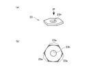
図2は、ワッシャ23の詳細な形状を示した説明図である。図2(a)には全体形状が示されており、図2(b)には、図2(a)中で矢印Pの方向から見たワッシャ23の形状が示されている。図示したように、ワッシャ23は、多角形形状(図示した例では六角形形状)の板状部材であり、中心には取付穴23hが形成されている。尚、取付穴23hは、本発明における「挿通穴」に対応する。また、本実施例では、ワッシャ23は六角形形状であるものとして説明するが、ワッシャ23の形状は六角形形状に限られるものではなく、取付穴23hの2.5倍以上(より好ましくは3倍以上)の半径を有する円周上の複数箇所が半径方向に膨出した形状であればよい。図2(b)では、取付穴23hの3倍の半径を有する円周が一点鎖線で示されており、一点鎖線の円周上の6箇所で半径方向に膨出した膨出部23aは、斜線を付して表示されている。
FIG. 2 is an explanatory diagram showing a detailed shape of the
図3は、防振部材22の詳細な形状を示した説明図である。図示するように、防振部材22の大まかな形状は、ワッシャ23と同じ多角形形状(ここでは六角形形状)であるが、ワッシャ23よりも大きな形状となっており、底面側の中央には、下方に向けて円柱状の取付用凸部22aが突設されている。そして、取付用凸部22aの中心軸上には取付穴22hが貫通されている。更に、防振部材22の上面側には、ワッシャ23と同じ大きさで同じ多角形形状の第1凹部22bが形成されている。
FIG. 3 is an explanatory diagram showing the detailed shape of the
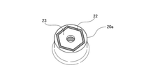
図4は、羽根車20の上面側の詳細な形状を示した説明図である。図4(a)には、上面側から見た羽根車20の全体形状が示されており、図4(b)には、羽根車20の上面側の中央部分(図中では太い破線で囲って表示)の詳細な形状が示されている。図4(b)に示されるように、羽根車20の中央には円柱形状の取付用ボス20aが形成されており、取付用ボス20aの中心軸上には取付穴20hが貫通している。そして、取付用ボス20aの上面側で取付穴20hが開口する箇所の周囲には、取付穴20hと同軸に、円形の取付用凹部20cが形成されている。更に、取付用凹部20cの周囲には、防振部材22と同じ大きさで同じ多角形形状の第2凹部20bが形成されている。
FIG. 4 is an explanatory view showing a detailed shape of the upper surface side of the
このように、取付用ボス20aの上面に形成された第2凹部20bは、防振部材22と同じ大きさで同じ多角形形状に形成されており、更に、防振部材22の上面に形成された第1凹部22bは、ワッシャ23と同じ大きさで同じ多角形形状に形成されている。このため、図5に示したように、取付用ボス20aの第2凹部20bに防振部材22を嵌め込んで、その防振部材22の第1凹部22bにワッシャ23を嵌め込むことができる。尚、防振部材22の底面側に突設した取付用凸部22aや、図1に示した底面側ワッシャ21の上面側に突設した取付用凸部21aの役割については後述する。
As described above, the
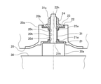
図6は、本実施例の羽根車20がモーター30の回転軸31に取り付けられている部分を拡大して示した断面図である。図示されるように、羽根車20は、取付用ボス20aの中心軸上に貫通する取付穴20hに、モーター30の回転軸31を挿通させて、取付穴20hから突出した回転軸31の先端に、防振部材22およびワッシャ23を介してナット24を用いて取り付けられている。
FIG. 6 is an enlarged cross-sectional view showing a portion of the
ここで、取付穴20hの内径は、モーター30から突出した回転軸31の外径よりも大きな値(代表的には、半径にして0.2ミリメートル程度、大きな値)に設定されている。また、防振部材22に形成された取付穴22h(図3参照)の内径は、回転軸31の外径と同じ大きさに設定されている。従って、回転軸31の外周面は、取付用ボス20aを貫通する取付穴20hの内周面には当接しないが、防振部材22に形成された取付穴22hの内周面には当接する。また、防振部材22の底面側からは円柱状の取付用凸部22aが突設されており、取付用凸部22aの外径は、取付用ボス20aの上面側に形成された円形の取付用凹部20cの内径と同じ大きさに設定されている。このため、防振部材22の取付用凸部22aの外周面は、取付用ボス20aに形成された取付用凹部20cの内周面に当接する。その結果、取付用ボス20aの上面側では、取付用ボス20aと回転軸31とは、ゴム製の防振部材22から突設した取付用凸部22aの外周面および内周面(すなわち、取付穴22h)を介して、半径方向に位置決めされている。
Here, the inner diameter of the mounting
取付用ボス20aの底面側に設けられたゴム製の底面側ワッシャ21についても、同様なことが当て嵌まる。すなわち、図6の断面図に示されるように、取付用ボス20aの底面側で取付穴20hが開口する位置の周辺には、取付穴20hと同軸に、円形の取付用凹部20dが形成されている。また、底面側ワッシャ21の上面側には円柱状の取付用凸部21aが突設されており(図1参照)、この取付用凸部21aが取付用ボス20aの取付用凹部20dに嵌め込まれている。
The same applies to the rubber
ここで、底面側ワッシャ21の取付用凸部21aの中心軸上を貫通する取付穴21hの内径は、回転軸31の外径と同じ大きさに設定されている。また、底面側ワッシャ21の取付用凸部21aの外径は、取付用ボス20aの底面側に形成された取付用凹部20dの内径と同じ大きさに設定されている。このため、取付用ボス20aの底面側では、取付用ボス20aと回転軸31とは、ゴム製の底面側ワッシャ21から突設した取付用凸部21aの外周面および内周面(すなわち、取付穴21h)を介して、半径方向に位置決めされている。
Here, the inner diameter of the mounting
このように、羽根車20の取付用ボス20aは、上面側に形成された取付用凹部20cおよび底面側に形成された取付用凹部20dと、防振部材22に突設させた22aと、底面側ワッシャ21に突設させた取付用凸部21aとによって、回転軸31に対して半径方向に位置決めされている。そして、羽根車20は、型を用いた射出成形と切削加工とによって形成されるから、羽根車20(および取付用ボス20a)の中心軸上に、取付穴20hや取付用凹部20c、取付用凹部20dを精度良く形成することができる。更に、防振部材22や底面側ワッシャ21についても、型を用いた射出成形によって形成されており、少なくとも寸法的に小さな取付用凸部22aや取付用凸部21aについては、精度良く形成することができる。このため、本実施例では、回転軸31に底面側ワッシャ21と羽根車20と防振部材22とを取り付けることによって、羽根車20と回転軸31とを、容易に芯出しされた状態(羽根車20の中心軸と回転軸31の中心軸とが重なった状態)とすることができる。
As described above, the mounting
そして、羽根車20と回転軸31とが芯出しされた状態で、防振部材22の上面側に形成された第1凹部22bにワッシャ23を嵌め込んで、回転軸31の先端部に形成された雄ネジ31aにナット24を螺合させることによって、ワッシャ23を介して、底面側ワッシャ21と羽根車20と防振部材22とを回転軸31に取り付ける。こうすれば、回転軸31とワッシャ23とはナット24を介して固体接触しているものの、ワッシャ23と羽根車20との間には、ゴム材料で形成された防振部材22が介在している。このため、モーター30で生じる軸方向信号(モーターの回転軸が軸方向に細かく進退動する振動)および回転方向振動(回転軸が一回転する間にモーターのトルクが細かく変動する振動)は、防振部材22によって遮断されるため、羽根車20に伝わることを抑制することができる。
Then, with the
その一方で、図5に示したように、取付用ボス20aの上面側に形成された第2凹部20bと、ワッシャ23との間には、ゴム材料で形成された防振部材22が介在されており、第2凹部20bとワッシャ23とは何れも多角形形状に形成されている。このため、モーター30で生じた回転トルクは、回転軸31およびナット24を介してワッシャ23に伝達され、多角形形状のワッシャ23がゴム製の防振部材22を圧縮する力として羽根車20に伝達される。このように、モーター30の回転トルクは、ワッシャ23が防振部材22を圧縮する力として羽根車20に伝達されるので、ワッシャ23と羽根車20との間は固定接触することなく、ゴム製の防振部材22を介して回転トルクを伝えているにも拘わらず、モーター30の回転トルクを羽根車20に効率よく伝えることができる。
On the other hand, as shown in FIG. 5, a vibration-
加えて、本実施例のワッシャ23は、防振部材22を介して羽根車20を取り付けるためには、必要以上に大きな寸法となっている。すなわち、図2を用いて前述したように、ワッシャ23は、中央に貫通する取付穴23hの2.5倍以上(より好ましくは3倍以上)の半径を有する円周上から、複数箇所(本実施例では6箇所)が半径方向に膨出した多角形形状に形成されている。このため、多角形形状のワッシャ23が防振部材22に当接する周長が長くなり、モーター30の回転トルクを伝えるために、多角形形状のワッシャ23がゴム製の防振部材22を圧縮する面積も大きくなる。その結果、大きな回転トルクを伝えることが可能となり、また、ゴム製の防振部材22が受ける応力が小さくなるので、モーター30でより大きな回転方向振動が発生しても、防振部材22で吸収することが可能となる。
In addition, the
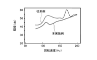
図7は、本実施例の送風ファン1による騒音低減効果を実測した結果を示す説明図である。図7では、羽根車20の回転速度に対する羽根車20の騒音を実測した結果が示されており、図中に示した実線は、本実施例の送風ファン1の実測結果を表している。また、図中に示した破線は、ゴム製の底面側ワッシャ21および防振部材22を除いて、羽根車20を取り付けた場合の実測結果を表している。図示したように、本実施例の送風ファン1では、回転速度の広い範囲に亘って、騒音が低減されていることが確認されている。
FIG. 7 is an explanatory diagram showing the results of actual measurement of the noise reduction effect of the blower fan 1 of this embodiment. FIG. 7 shows the results of actual measurement of the noise of the
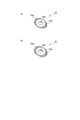
以上に説明した本実施例では、ワッシャ23が多角形形状に形成されているものとして説明した。ワッシャ23が多角形形状に形成されている場合、ワッシャ23が嵌め込まれる防振部材22の第1凹部22bも多角形形状となり、防振部材22も多角形形状となる。そして、羽根車20の上面側に形成される第2凹部20bも多角形形状となる。しかし、ワッシャ23が多角形形状に形成されている目的は、モーター30で発生した回転トルクを、ワッシャ23がゴム製の防振部材22を圧縮する力として羽根車20に伝えるためである。従って、モーター30で発生した回転トルクを、ワッシャ23がゴム製の防振部材22を圧縮する力として羽根車20に伝えることができれば、ワッシャ23の形状は必ずしも多角形形状に限られない。
In the present embodiment described above, it is assumed that the
例えば、図8(a)に例示したように、ワッシャ23を楕円形状としても良い。すなわち、中央に形成された取付穴23hの2.5倍以上(より好ましくは3倍以上)の半径を有する円周(図中に一点鎖線で表示)上で、取付穴23hを介して互いに向き合う2箇所を半径方向に膨出させて、ワッシャ23が楕円形状となるように膨出部23a(図中で斜線を付して表示)を形成しても良い。この場合は、ワッシャ23が嵌め込まれる防振部材22の第1凹部22bも楕円形状となり、防振部材22も楕円形状となる。そして、羽根車20の上面側に形成される第2凹部20bも楕円形状となる。
For example, as illustrated in FIG. 8A, the
あるいは、図8(b)に例示したように、ワッシャ23を小判形状としても良い。すなわち、中央に形成された取付穴23hの2.5倍以上(より好ましくは3倍以上)の半径を有する円周(図中に一点鎖線で表示)上で、取付穴23hを介して互いに向き合う2箇所を半径方向に膨出させて、ワッシャ23が小判形状となるように膨出部23a(図中で斜線を付して表示)を形成しても良い。尚、小判形状とは、同じ直径を有する2つの半円と、半円の直径と同じ長さの辺を有する長方形(あるいは正方形)とを組み合わせて形成される形状である。すなわち、長方形の4つの辺の中で、半円の直径と同じ長さを有する長方形の2つの辺のそれぞれに、半円の直径がちょうど重なるような状態で、2つの半円と長方形とを組み合わせて形成した形状である。また、ワッシャ23が小判形状の場合は、ワッシャ23が嵌め込まれる防振部材22の第1凹部22bも小判形状となり、防振部材22も小判形状となる。更に、羽根車20の上面側に形成される第2凹部20bも小判形状となる。
Alternatively, as illustrated in FIG. 8B, the
以上、本実施例および変形例の送風ファン1について説明したが、本発明は上記の実施例に限られるものではなく、その要旨を逸脱しない範囲において種々の態様で実施することが可能である。 Although the blower fan 1 of the present embodiment and the modified example has been described above, the present invention is not limited to the above embodiment, and can be carried out in various embodiments without departing from the gist thereof.
1…送風ファン、 10…本体ケース、 20…羽根車、
20a…取付用ボス、 20b…第2凹部、 20c…取付用凹部、
20d…取付用凹部、 20h…取付穴、 21…底面側ワッシャ、
21a…取付用凸部、 21h…取付穴、 22…防振部材、
22a…取付用凸部、 22b…第1凹部、 22h…取付穴、
23…ワッシャ、 23a…膨出部、 23h…取付穴、
24…ナット、 30…モーター、 31…回転軸、 31a…雄ネジ。
1 ... Blower fan, 10 ... Main body case, 20 ... Impeller,
20a ... mounting boss, 20b ... second recess, 20c ... mounting recess,
20d ... mounting recess, 20h ... mounting hole, 21 ... bottom washer,
21a ... Convex part for mounting, 21h ... Mounting hole, 22 ... Anti-vibration member,
22a ... Convex part for mounting, 22b ... First concave part, 22h ... Mounting hole,
23 ... washer, 23a ... bulge, 23h ... mounting hole,
24 ... nut, 30 ... motor, 31 ... rotating shaft, 31a ... male screw.
Claims (5)
前記ワッシャは、前記回転軸が挿通される挿通穴を中心とする円形形状から円周方向の複数箇所が半径方向に膨出し、且つ、前記複数箇所の間には前記円形形状から膨出していない箇所が残存した特定形状の板状部材であり、
前記ワッシャと前記羽根車との間には、弾性材料によって形成された防振部材が介在されており、
前記防振部材の形状は、前記ワッシャよりも大きな前記特定形状で、上面側には前記ワッシャが嵌め込まれる前記特定形状の第1凹部が形成されており、
前記羽根車の上面には、前記防振部材が嵌め込まれる前記特定形状の第2凹部が形成されている
ことを特徴とする送風ファン。 An impeller with a mounting hole penetrating on the central shaft, a motor with a rotating shaft inserted through the mounting hole, a washer through which the rotating shaft protruding from the mounting hole is inserted, and the impeller via the washer. In a blower fan, which is provided with a mounting member for attaching the impeller to the rotating shaft by being attached to the rotating shaft in a pressed state, and blows air by rotating the impeller using the motor.
The washer has a plurality of points in the circumferential direction bulging in the radial direction from a circular shape centered on an insertion hole through which the rotation axis is inserted , and bulging from the circular shape between the plurality of places. It is a plate-shaped member with a specific shape that has not been left .
A vibration-proof member formed of an elastic material is interposed between the washer and the impeller.
The shape of the anti-vibration member is the specific shape larger than the washer, and the first recess of the specific shape into which the washer is fitted is formed on the upper surface side.
A blower fan characterized in that a second recess having the specific shape into which the vibration isolator member is fitted is formed on the upper surface of the impeller.
前記ワッシャは、前記挿通穴の半径の2.5倍よりも大きな半径の円周から前記複数箇所が膨出した形状である
ことを特徴とする送風ファン。 In the blower fan according to claim 1,
The washer is a blower fan having a shape in which the plurality of points bulge from a circumference having a radius larger than 2.5 times the radius of the insertion hole.
前記羽根車は、上面側に設けられた前記防振部材と、ゴム材料で形成されて底面側に設けられた底面側ワッシャとで挟持された状態で、前記回転軸に取り付けられている
ことを特徴とする送風ファン。 In the blower fan according to claim 1 or 2.
The impeller is attached to the rotating shaft in a state of being sandwiched between the anti-vibration member provided on the upper surface side and the bottom surface side washer formed of a rubber material and provided on the bottom surface side. A characteristic blower fan.
前記ワッシャは、多角形形状に形成されている
ことを特徴とする送風ファン。 In the blower fan according to claim 1 to claim 3.
The washer is a blower fan characterized by being formed in a polygonal shape.
前記ワッシャは、楕円形状あるいは小判形状に形成されている
ことを特徴とする送風ファン。 In the blower fan according to claim 1 to claim 3.
The washer is a blower fan characterized in that it is formed in an elliptical shape or an oval shape.
Priority Applications (2)
| Application Number | Priority Date | Filing Date | Title |
|---|---|---|---|
| JP2018102526A JP6991925B2 (en) | 2018-05-29 | 2018-05-29 | Blower fan |
| US16/270,362 US10883514B2 (en) | 2018-05-29 | 2019-02-07 | Blower fan |
Applications Claiming Priority (1)
| Application Number | Priority Date | Filing Date | Title |
|---|---|---|---|
| JP2018102526A JP6991925B2 (en) | 2018-05-29 | 2018-05-29 | Blower fan |
Publications (2)
| Publication Number | Publication Date |
|---|---|
| JP2019206940A JP2019206940A (en) | 2019-12-05 |
| JP6991925B2 true JP6991925B2 (en) | 2022-01-13 |
Family
ID=68694528
Family Applications (1)
| Application Number | Title | Priority Date | Filing Date |
|---|---|---|---|
| JP2018102526A Active JP6991925B2 (en) | 2018-05-29 | 2018-05-29 | Blower fan |
Country Status (2)
| Country | Link |
|---|---|
| US (1) | US10883514B2 (en) |
| JP (1) | JP6991925B2 (en) |
Families Citing this family (2)
| Publication number | Priority date | Publication date | Assignee | Title |
|---|---|---|---|---|
| KR20230038970A (en) * | 2021-09-13 | 2023-03-21 | 주식회사 엠아이디자인 | Blower |
| IT202100028118A1 (en) * | 2021-11-04 | 2023-05-04 | Regal Beloit Italy S P A | FAN FOR FAN MOTORS FOR COUPLING TO DIFFERENT TYPES OF HUBS |
Citations (1)
| Publication number | Priority date | Publication date | Assignee | Title |
|---|---|---|---|---|
| JP2002276594A (en) | 2001-03-15 | 2002-09-25 | Sanko Gosei Ltd | Propeller fan |
Family Cites Families (5)
| Publication number | Priority date | Publication date | Assignee | Title |
|---|---|---|---|---|
| US3084963A (en) * | 1960-07-29 | 1963-04-09 | Lau Blower Co | Resilent fan hub assembly |
| JPS6329126A (en) | 1986-07-21 | 1988-02-06 | Matsushita Electric Ind Co Ltd | Fan vibration prevention device for air conditioner |
| JPH10159792A (en) * | 1996-12-02 | 1998-06-16 | Mitsubishi Electric Corp | Blower |
| US6190134B1 (en) * | 1999-09-28 | 2001-02-20 | Molded Products Company | Fan blade stabilization apparatus |
| JPWO2016013096A1 (en) | 2014-07-25 | 2017-04-27 | ジョンソンコントロールズ ヒタチ エア コンディショニング テクノロジー(ホンコン)リミテッド | Blower and air conditioner |
-
2018
- 2018-05-29 JP JP2018102526A patent/JP6991925B2/en active Active
-
2019
- 2019-02-07 US US16/270,362 patent/US10883514B2/en active Active
Patent Citations (1)
| Publication number | Priority date | Publication date | Assignee | Title |
|---|---|---|---|---|
| JP2002276594A (en) | 2001-03-15 | 2002-09-25 | Sanko Gosei Ltd | Propeller fan |
Also Published As
| Publication number | Publication date |
|---|---|
| US10883514B2 (en) | 2021-01-05 |
| US20190368503A1 (en) | 2019-12-05 |
| JP2019206940A (en) | 2019-12-05 |
Similar Documents
| Publication | Publication Date | Title |
|---|---|---|
| JP3264616B2 (en) | Elastic joints in steering devices | |
| JPWO2019039310A1 (en) | Grommet | |
| JP4128889B2 (en) | Blower motor support structure | |
| JP2019206940A (en) | Blower fan | |
| WO2008059738A1 (en) | Boss structure of impeller of blower and impeller of blower having same | |
| JP2004019678A (en) | Power transmission device | |
| JPH07248045A (en) | Dynamic damper | |
| JP2008236981A (en) | Mounting structure for electric motor | |
| WO2018225636A1 (en) | Buffer member and air-blowing device provided with buffer member | |
| JPH10159792A (en) | Blower | |
| JP5792117B2 (en) | Fixed structure | |
| JP2004304857A (en) | Motor-mounting structure | |
| JPH05231386A (en) | Blade locking washer | |
| JPH08170690A (en) | Floating rubber | |
| JP2599818Y2 (en) | Coupling | |
| JP2008196611A (en) | Vibration isolator | |
| KR200361418Y1 (en) | Center bearing fixing structure of propeller shaft | |
| JP2550963Y2 (en) | mount | |
| JP2011140977A (en) | Dynamic damper | |
| JP3479854B2 (en) | damper | |
| JPS6027237Y2 (en) | Shaft anti-vibration support device | |
| JPH0626766Y2 (en) | Rubber gear | |
| JPH04262098A (en) | Fitting device for impeller | |
| JPH0518905Y2 (en) | ||
| JPH0714257U (en) | Rotating cam structure |
Legal Events
| Date | Code | Title | Description |
|---|---|---|---|
| A621 | Written request for application examination |
Free format text: JAPANESE INTERMEDIATE CODE: A621 Effective date: 20201221 |
|
| A131 | Notification of reasons for refusal |
Free format text: JAPANESE INTERMEDIATE CODE: A131 Effective date: 20210914 |
|
| A521 | Request for written amendment filed |
Free format text: JAPANESE INTERMEDIATE CODE: A523 Effective date: 20211028 |
|
| TRDD | Decision of grant or rejection written | ||
| A01 | Written decision to grant a patent or to grant a registration (utility model) |
Free format text: JAPANESE INTERMEDIATE CODE: A01 Effective date: 20211116 |
|
| A61 | First payment of annual fees (during grant procedure) |
Free format text: JAPANESE INTERMEDIATE CODE: A61 Effective date: 20211208 |
|
| R150 | Certificate of patent or registration of utility model |
Ref document number: 6991925 Country of ref document: JP Free format text: JAPANESE INTERMEDIATE CODE: R150 |
|
| R250 | Receipt of annual fees |
Free format text: JAPANESE INTERMEDIATE CODE: R250 |
|
| R250 | Receipt of annual fees |
Free format text: JAPANESE INTERMEDIATE CODE: R250 |