JP6996830B2 - Pressure reducing valve - Google Patents
Pressure reducing valve Download PDFInfo
- Publication number
- JP6996830B2 JP6996830B2 JP2017234759A JP2017234759A JP6996830B2 JP 6996830 B2 JP6996830 B2 JP 6996830B2 JP 2017234759 A JP2017234759 A JP 2017234759A JP 2017234759 A JP2017234759 A JP 2017234759A JP 6996830 B2 JP6996830 B2 JP 6996830B2
- Authority
- JP
- Japan
- Prior art keywords
- valve
- cylinder
- valve seat
- piston head
- pressure reducing
- Prior art date
- Legal status (The legal status is an assumption and is not a legal conclusion. Google has not performed a legal analysis and makes no representation as to the accuracy of the status listed.)
- Active
Links
Images


Landscapes
- Safety Valves (AREA)
- Control Of Fluid Pressure (AREA)
Description
本発明は、一次側通路と二次側通路との境界部の流路面積を可変調整する止水機能を有する弁体を備える減圧弁機構と、二次側通路の内圧に応じて開閉する逃し弁機構とを備える減圧弁に関するものである。 The present invention comprises a pressure reducing valve mechanism provided with a valve body having a water blocking function for variably adjusting the flow path area at the boundary between the primary side passage and the secondary side passage, and a relief valve that opens and closes according to the internal pressure of the secondary side passage. It relates to a pressure reducing valve provided with a valve mechanism.
一次側通路と二次側通路との境界部の流路面積を可変調整する止水機能を有する減圧弁機構と、二次側通路の内圧に応じて開閉する逃し弁機構とを備え、減圧弁機構と逃し弁機構とは中心軸線を共有するリフト弁機構である減圧弁であって、ボディと、ボディの一部によって形成されたシリンダと、シリンダ内で往復摺動するピストンヘッドと、ピストンヘッドとシリンダ内周面との摺接部をシールするシール部材と、ピストンヘッドの一端部から延びてシリンダの一端部からシリンダ外の二次側通路へ突出するピストンロッドと、シリンダの前記一端部が形成する第1弁座と、ピストンロッドのシリンダ外へ突出した一端部に固定されて第1弁座と対峙する第1弁体と、シリンダ周壁のピストンロッドに対峙する部位に形成された開口と、ピストンヘッドを閉弁方向へ付勢する第1バネと、ピストンヘッドの他端部に一端部が対峙する筒体と、前記筒体に中心部が固定されたダイアフラムと、ボディの一部により形成されダイアフラムに対峙しダイアフラムとシリンダとピストンヘッドと協働して二次側通路に連通する感圧室を形成するダイアフラムケースと、ダイアフラムを感圧室側へ押圧する第2バネと、第2バネと前記筒体の他端部とを収容すると共にダイアフラムケースと協働してダイアフラムの周縁部を挟持するバネケースと、前記筒体の前記一端部に配設された第2弁座又は第2弁体と、ピストンヘッドの他端部に係合し前記筒体の前記一端部に配設された第2弁座又は第2弁体に対峙する第2弁体又は第2弁座とを備え、第1弁体と第1弁座とが減圧弁機構の弁体と弁座とを形成し、第2弁座と第2弁体とが逃し弁機構の弁座と弁体を形成した減圧弁が、特許文献1に開示されている。
特許文献1の減圧弁には、減圧弁機構と逃し弁機構とを一体化できるという利点がある。
It is equipped with a pressure reducing valve mechanism having a water stop function that variably adjusts the flow path area at the boundary between the primary side passage and the secondary side passage, and a relief valve mechanism that opens and closes according to the internal pressure of the secondary side passage. The mechanism and the relief valve mechanism are pressure reducing valves that are lift valve mechanisms that share the central axis, and are a body, a cylinder formed by a part of the body, a piston head that slides back and forth in the cylinder, and a piston head. A sealing member that seals the sliding contact portion between the piston and the inner peripheral surface of the cylinder, a piston rod that extends from one end of the piston head and projects from one end of the cylinder to the secondary passage outside the cylinder, and the one end of the cylinder. The first valve seat to be formed, the first valve body fixed to one end of the piston rod protruding outside the cylinder and facing the first valve seat, and the opening formed at the portion facing the piston rod on the peripheral wall of the cylinder. , The first spring that urges the piston head in the valve closing direction, the cylinder whose one end faces the other end of the piston head, the diaphragm whose center is fixed to the cylinder, and a part of the body. A diaphragm case that is formed and faces the diaphragm and cooperates with the diaphragm, the cylinder, and the piston head to form a pressure-sensitive chamber that communicates with the secondary side passage, and a second spring that presses the diaphragm toward the pressure-sensitive chamber side, and a second. A spring case that accommodates the spring and the other end of the cylinder and cooperates with the diaphragm case to sandwich the peripheral edge of the diaphragm, and a second valve seat or a second valve seat or a second valve seat arranged at the one end of the cylinder. It is provided with a valve body and a second valve seat or a second valve seat that engages with the other end of the piston head and is disposed at the one end of the cylinder and faces the second valve seat or the second valve body. , The first valve body and the first valve seat form the valve body and the valve seat of the pressure reducing valve mechanism, and the second valve seat and the second valve body form the valve seat and the valve body of the relief valve mechanism. The valve is disclosed in
The pressure reducing valve of
特許文献1に開示された減圧弁には、第1弁体がピストンヘッドとシリンダとの摺接部においてのみ減圧弁機構の中心軸線方向にガイドされているので、部品精度や組立精度の影響を受け易く、第1弁体が減圧弁機構の閉鎖面に対して傾き、減圧弁機構のスムーズな動きや止水機能に支障を生ずる場合があるという問題がある。また、筒体の前記一端部に配設された第2弁座又は第2弁体が逃し弁機構の中心軸線方向にガイドされていないので、部品精度や組立精度の影響を受け易く、第2弁座又は第2弁体が逃し弁機構の閉鎖面に対して傾き、逃し弁機構のスムーズな動きや止水機能に支障を生ずる場合があるという問題がある。
本発明は上記問題に鑑みてなされたものであり、一次側通路と二次側通路との境界部の流路面積を可変調整する止水機能を有する減圧弁機構と、二次側通路の内圧に応じて開閉する逃し弁機構とを備え、減圧弁機構と逃し弁機構とは中心軸線を共有するリフト弁機構である減圧弁であって、ボディと、ボディの一部によって形成されたシリンダと、シリンダ内で往復摺動するピストンヘッドと、ピストンヘッドとシリンダ内周面との摺接部をシールするシール部材と、ピストンヘッドの一端部から延びてシリンダの一端部からシリンダ外の二次側通路へ突出するピストンロッドと、シリンダの前記一端部が形成する第1弁座と、ピストンロッドのシリンダ外へ突出した一端部に固定されて第1弁座と対峙する第1弁体と、シリンダ周壁のピストンロッドに対峙する部位に形成された開口と、ピストンヘッドを閉弁方向へ付勢する第1バネと、ピストンヘッドの他端部に一端部が対峙する筒体と、前記筒体に中心部が固定されたダイアフラムと、ボディの一部により形成されダイアフラムに対峙しダイアフラムとシリンダとピストンヘッドと協働して二次側通路に連通する感圧室を形成するダイアフラムケースと、ダイアフラムを感圧室側へ押圧する第2バネと、第2バネと前記筒体の他端部とを収容すると共にダイアフラムケースと協働してダイアフラムの周縁部を挟持するバネケースと、前記筒体の前記一端部に配設された第2弁座又は第2弁体と、ピストンヘッドの他端部に係合し前記筒体の前記一端部に配設された第2弁座又は第2弁体に対峙する第2弁体又は第2弁座とを備え、第1弁体と第1弁座とが減圧弁機構の弁体と弁座とを形成し、第2弁座と第2弁体とが逃し弁機構の弁座と弁体を形成した減圧弁であって、減圧弁機構の止水機能と逃し弁機構の止水機能とに支障を来さない減圧弁を提供することを目的とする。
In the pressure reducing valve disclosed in
The present invention has been made in view of the above problems, and is a pressure reducing valve mechanism having a water stop function for variably adjusting the flow path area at the boundary between the primary side passage and the secondary side passage, and the internal pressure of the secondary side passage. The pressure reducing valve mechanism and the relief valve mechanism are a pressure reducing valve that is a lift valve mechanism that shares a central axis, and is provided with a relief valve mechanism that opens and closes according to the conditions of the body and a cylinder formed by a part of the body. , A piston head that slides back and forth in the cylinder, a sealing member that seals the sliding contact between the piston head and the inner peripheral surface of the cylinder, and a secondary side outside the cylinder that extends from one end of the piston head and extends from one end of the cylinder. A piston rod protruding into the passage, a first valve seat formed by the one end of the cylinder, a first valve body fixed to one end of the piston rod protruding out of the cylinder and facing the first valve seat, and a cylinder. An opening formed in a portion of the peripheral wall facing the piston rod, a first spring for urging the piston head in the valve closing direction, a cylinder having one end facing the other end of the piston head, and the cylinder. A diaphragm with a fixed center, a diaphragm case formed by a part of the body and facing the diaphragm, and a diaphragm case and a diaphragm that cooperate with the cylinder and the piston head to form a pressure-sensitive chamber that communicates with the secondary passage. A second spring that presses against the pressure-sensitive chamber side, a spring case that accommodates the second spring and the other end of the cylinder, and cooperates with the diaphragm case to sandwich the peripheral edge of the diaphragm, and the cylinder. The second valve seat or the second valve body disposed at one end and the second valve seat or the second valve body disposed at the one end of the cylinder engaged with the other end of the piston head. A second valve body or a second valve seat facing each other is provided, and the first valve body and the first valve seat form a valve body and a valve seat of a pressure reducing valve mechanism, and the second valve seat and the second valve seat Is a pressure reducing valve forming the valve seat and valve body of the relief valve mechanism, and the purpose is to provide a pressure reducing valve that does not interfere with the water stop function of the pressure reducing valve mechanism and the water stopping function of the relief valve mechanism. do.
上記課題を解決するために、本発明においては、一次側通路と二次側通路との境界部の流路面積を可変調整する止水機能を有する減圧弁機構と、二次側通路の内圧に応じて開閉する逃し弁機構とを備え、減圧弁機構と逃し弁機構とは中心軸線を共有するリフト弁機構である減圧弁であって、ボディと、ボディの一部によって形成されたシリンダと、シリンダ内で往復摺動するピストンヘッドと、ピストンヘッドとシリンダ内周面との摺接部をシールするシール部材と、ピストンヘッドの一端部から延びてシリンダの一端部からシリンダ外の二次側通路へ突出するピストンロッドと、シリンダの前記一端部が形成する第1弁座と、ピストンロッドのシリンダ外へ突出した一端部に固定されて第1弁座と対峙する第1弁体と、シリンダ周壁のピストンロッドに対峙する部位に形成された開口と、ピストンヘッドを閉弁方向へ付勢する第1バネと、ピストンヘッドの他端部に一端部が対峙する筒体と、前記筒体に中心部が固定されたダイアフラムと、ボディの一部により形成されダイアフラムに対峙しダイアフラムとシリンダとピストンヘッドと協働して二次側通路に連通する感圧室を形成するダイアフラムケースと、ダイアフラムを感圧室側へ押圧する第2バネと、第2バネと前記筒体の他端部とを収容すると共にダイアフラムケースと協働してダイアフラムの周縁部を挟持するバネケースと、前記筒体の前記一端部に配設された第2弁座又は第2弁体と、ピストンヘッドの他端部に係合し前記筒体の前記一端部に配設された第2弁座又は第2弁体に対峙する第2弁体又は第2弁座とを備え、第1弁体と第1弁座とが減圧弁機構の弁体と弁座とを形成し、第2弁座と第2弁体とが逃し弁機構の弁座と弁体を形成し、減圧弁機構の第1弁体が減圧弁機構の中心軸線方向に離隔した2箇所で減圧弁機構の中心軸線方向にガイドされ、前記筒体の前記一端部に配設された第2弁座又は第2弁体が逃し弁機構の中心軸線方向に離隔する2箇所で逃し弁機構の中心軸線方向にガイドされていることを特徴とする減圧弁を提供する。
本発明に係る減圧弁においては、減圧弁機構の第1弁体は、減圧弁機構の中心軸線方向に離隔した2箇所で減圧弁機構の中心軸線方向にガイドされているので、部品精度や組立精度の影響を受け難く、減圧弁機構の閉鎖面に対して傾かず、減圧弁機構のスムーズな動きや止水機能に支障を来さない。筒体の一端部に配設された第2弁座又は第2弁体は、逃し弁機構の中心軸線方向に離隔する2箇所で逃し弁機構の中心軸線方向にガイドされているので、部品精度や組立精度の影響を受け難く、逃し弁機構の閉鎖面に対して傾かない。従って、ピストンヘッドの他端部に係合した第2弁体又は第2弁座を逃し弁機構の中心軸線方向に離隔する2箇所で逃し弁機構の中心軸線方向にガイドするか或いはピストンヘッドの他端部に固定すれば、ピストンヘッドの他端部に係合した第2弁体又は第2弁座も部品精度や組立精度の影響を受け難く、逃し弁機構の閉鎖面に対して傾かず、逃し弁機構のスムーズな動きや止水機能に支障を来さない。
In order to solve the above problems, in the present invention, a pressure reducing valve mechanism having a water stop function for variably adjusting the flow path area at the boundary between the primary side passage and the secondary side passage and the internal pressure of the secondary side passage are used. It is equipped with a relief valve mechanism that opens and closes accordingly, and the pressure reducing valve mechanism and the relief valve mechanism are pressure reducing valves that are lift valve mechanisms that share the central axis, and include a body, a cylinder formed by a part of the body, and a cylinder. A piston head that slides back and forth in the cylinder, a sealing member that seals the sliding contact between the piston head and the inner peripheral surface of the cylinder, and a secondary side passage outside the cylinder that extends from one end of the piston head and extends from one end of the cylinder. The piston rod protruding to the top, the first valve seat formed by the one end of the cylinder, the first valve body fixed to the one end of the piston rod protruding out of the cylinder and facing the first valve seat, and the peripheral wall of the cylinder. An opening formed in a portion facing the piston rod, a first spring for urging the piston head in the valve closing direction, a cylinder having one end facing the other end of the piston head, and a center of the cylinder. Feel the diaphragm and the diaphragm case, which is formed by a part of the body and faces the diaphragm, and forms a pressure-sensitive chamber that communicates with the diaphragm, cylinder, and piston head to communicate with the secondary side passage. A spring case that accommodates the second spring that presses toward the compression chamber side, the second spring, and the other end of the cylinder, and also cooperates with the diaphragm case to sandwich the peripheral edge of the diaphragm, and the one end of the cylinder. The second valve seat or the second valve body disposed in the portion engages with the other end of the piston head and faces the second valve seat or the second valve body disposed in the one end portion of the cylinder. A second valve body or a second valve seat is provided, and the first valve body and the first valve seat form a valve body and a valve seat of a pressure reducing valve mechanism, and the second valve seat and the second valve seat are formed. A valve seat and a valve body of the relief valve mechanism are formed, and the first valve body of the pressure reducing valve mechanism is guided in the central axis direction of the pressure reducing valve mechanism at two points separated from each other in the central axis direction of the pressure reducing valve mechanism. A pressure reducing valve characterized in that the second valve seat or the second valve body disposed at one end thereof is guided in the central axis direction of the relief valve mechanism at two locations separated in the center axis direction of the relief valve mechanism. I will provide a.
In the pressure reducing valve according to the present invention, the first valve body of the pressure reducing valve mechanism is guided in the direction of the center axis of the pressure reducing valve mechanism at two locations separated in the direction of the center axis of the pressure reducing valve mechanism. It is not easily affected by accuracy, does not tilt with respect to the closed surface of the pressure reducing valve mechanism, and does not interfere with the smooth movement and water stopping function of the pressure reducing valve mechanism. The second valve seat or the second valve body arranged at one end of the cylinder is guided in the direction of the center axis of the relief valve mechanism at two points separated in the direction of the center axis of the relief valve mechanism. It is not easily affected by the assembly accuracy and does not tilt with respect to the closed surface of the relief valve mechanism. Therefore, the second valve body or the second valve seat engaged with the other end of the piston head is guided in the direction of the center axis of the relief valve mechanism at two points separated in the direction of the center axis of the relief valve mechanism, or the piston head. If fixed to the other end, the second valve body or second valve seat engaged with the other end of the piston head is not easily affected by the accuracy of parts and assembly, and does not tilt with respect to the closed surface of the relief valve mechanism. , Does not interfere with the smooth movement of the relief valve mechanism and the water stop function.
本発明の好ましい態様においては、ピストンヘッドの他端部に係合する第2弁体又は第2弁座とピストンヘッドの他端部との間に前記第2弁体又は第2弁座を逃し弁機構の閉弁方向へ付勢する第3バネが配設され、前記第2弁体又は第2弁座の逃し弁機構閉弁方向への移動を規制するストッパーがピストンヘッドの他端部に配設され、前記第2弁体又は第2弁座は逃し弁機構の中心軸線方向に離隔する2箇所で逃し弁機構の中心軸線方向にガイドされている。
第3バネのバネ定数を小さな値に設定することにより、第2弁体又は第2弁座を構成するシール材の経時的な性能劣化を防止できる。ストッパーの配設により、逃し弁機構を確実に開弁させることができる。ピストンヘッドの他端部に係合する第2弁体又は第2弁座とピストンヘッドの他端部との間に前記第2弁体又は前記第2弁座を逃し弁機構の閉弁方向へ付勢する第3バネが配設されている場合、第2弁体又は第2弁座が逃し弁機構の中心軸線方向に離隔する2箇所で逃し弁機構の中心軸線方向にガイドされていれば、第2弁体又は第2弁座は逃し弁機構の閉鎖面に対して傾かず、逃し弁機構のスムーズな動きや止水機能に支障を来さない。
本発明の好ましい態様においては、ピストンヘッドの他端部に係合する第2弁体又は第2弁座のガイドに遊びが設けられている。
万一部品精度や組立精度の影響を受けて第2弁座又は第2弁体が逃し弁機構の閉鎖面に対して僅かに傾いたとしても、ピストンヘッドの他端部に係合する第2弁体又は第2弁座のガイドに遊びが設けられていれば、2弁体又は第2弁座は第2弁座又は第2弁体に追随して傾くことができ、第2弁座又は第2弁体に正対して密着することができる。
本発明の好ましい態様においては、ピストンヘッドの他端部に係合する第2弁体又は第2弁座は、押して捩じるバヨネット式接続機構によりピストンヘッドの他端部に取り付けられている。
押して捩じるバヨネット式接続機構により、第2弁体又は第2弁座をピストンヘッドの他端部に容易に取り付けることができる。
本発明の好ましい態様においては、ピストンヘッドの他端部に係合する第2弁体又は第2弁座はピストンヘッドの他端部に固定されている。
ピストンヘッドの他端部に係合する第2弁体又は第2弁座を、逃し弁機構の中心軸線方向に離隔する2箇所で逃し弁機構の中心軸線方向にガイドされたピストンヘッドの他端部に固定すれば、前記第2弁体又は第2弁座も逃し弁機構の中心軸線方向に離隔する2箇所で逃し弁機構の中心軸線方向にガイドされることになり、逃し弁の閉鎖面に対して傾かない。
In a preferred embodiment of the present invention, the second valve body or the second valve seat is missed between the second valve body or the second valve seat engaged with the other end of the piston head and the other end of the piston head. A third spring that urges the valve mechanism in the valve closing direction is arranged, and a stopper that restricts the movement of the second valve body or the second valve seat in the valve closing direction is provided at the other end of the piston head. The second valve body or the second valve seat is arranged and guided in the direction of the center axis of the relief valve mechanism at two locations separated in the direction of the center axis of the relief valve mechanism.
By setting the spring constant of the third spring to a small value, it is possible to prevent the performance deterioration of the sealing material constituting the second valve body or the second valve seat over time. By arranging the stopper, the relief valve mechanism can be reliably opened. The second valve body or the second valve seat is released between the second valve body or the second valve seat engaged with the other end of the piston head and the other end of the piston head in the valve closing direction of the valve mechanism. When the urging third spring is arranged, if the second valve body or the second valve seat is guided in the direction of the center axis of the relief valve mechanism at two points separated in the direction of the center axis of the relief valve mechanism. The second valve body or the second valve seat does not tilt with respect to the closing surface of the relief valve mechanism, and does not interfere with the smooth movement of the relief valve mechanism and the water blocking function.
In a preferred embodiment of the present invention , play is provided in the guide of the second valve body or the second valve seat that engages with the other end of the piston head.
Even if the second valve seat or the second valve body is slightly tilted with respect to the closing surface of the relief valve mechanism due to the influence of component accuracy and assembly accuracy, the second valve seat that engages with the other end of the piston head. If the valve body or the guide of the second valve seat is provided with play , the second valve body or the second valve seat can be tilted following the second valve seat or the second valve body, and the second valve seat or the second valve seat or the second valve seat can be tilted. It can be in close contact with the second valve body.
In a preferred embodiment of the present invention, the second valve body or the second valve seat that engages with the other end of the piston head is attached to the other end of the piston head by a push-twist bayonet type connection mechanism.
The push-twist bayonet connection mechanism allows the second valve body or second valve seat to be easily attached to the other end of the piston head.
In a preferred embodiment of the present invention, the second valve body or the second valve seat engaged with the other end of the piston head is fixed to the other end of the piston head.
The other end of the piston head in which the second valve body or the second valve seat engaged with the other end of the piston head is guided in the central axis direction of the relief valve mechanism at two points separated in the center axis direction of the relief valve mechanism. If fixed to the portion, the second valve body or the second valve seat will also be guided in the direction of the center axis of the relief valve mechanism at two locations separated in the direction of the center axis of the relief valve mechanism, and the closing surface of the relief valve will be guided. Do not lean against.
本発明の実施例に係る減圧弁を説明する。
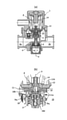
図1に示すように、減圧弁1はボディ2を備えている。ボディ2は、一次側通路2aと二次側通路2bとが内部に形成されると共に、シリンダ2cとダイアフラムケース2dとを有している。
減圧弁1は、シリンダ2c内で往復摺動するピストンヘッド3と、ピストンヘッド3とシリンダ2c内周面との摺接部をシールするオーリング4と、ピストンヘッド3の一端部から延びてシリンダ2cの一端部からシリンダ2c外の二次側通路2bへ突出するピストンロッド5と、シリンダ2cの前記一端部が形成する第1弁座6と、ピストンロッド5のシリンダ2c外へ突出した一端部に固定されて第1弁座6と対峙する第1弁体7と、第1弁体7に係合してピストンヘッド3を閉弁方向へ付勢する第1バネ8と、ボディ2の二次側通路2bを形成する部位に水密に螺合固定されて第1バネ8を収容すると共に第1弁体7を往復摺動可能に収容する第1バネ8用のバネ押さえ9と、シリンダ2c周壁のピストンロッド5に対峙する部位に形成された開口10と、ピストンヘッド3の他端部に一端部が対峙する筒体11と、筒体11の前記一端部の近傍部に中心部が固定されたダイアフラム12と、ボディ2の一部により形成されダイアフラム12に対峙しダイアフラム12とシリンダ2cとピストンヘッド3と協働して二次側通路2bに連通する感圧室13を形成する前述のダイアフラムケース2dと、ダイアフラム12を感圧室13側へ押圧する第2バネ14と、第2バネ14と筒体11の長手方向中央部と他端部とを収容すると共にダイアフラムケース2dと協働してダイアフラム12の周縁部を挟持するバネケース15と、筒体11の前記一端部に配設された第2弁座16と、第3バネ17を介してピストンヘッド3の他端部に係合し第2弁座16に対峙する第2弁体18と、を備えている。第3バネ17のバネ定数は小さな値に設定されている。
The pressure reducing valve according to the embodiment of the present invention will be described.
As shown in FIG. 1, the
The
筒体11は、感圧室13内に配設された一端部を有する第1部分11aと、バネケース15内に配設されて第1部分11aに連結固定された第2部分11bとを備えている。第1部分11aと第2部分11bとが協働してダイアフラム12の中心部を挟持している。第1部分11aの感圧室13内に配設された一端部には前述のごとく第2弁座16が配設されると共に、前記一端部はシリンダ2cに往復摺動可能に外嵌合しており、当該嵌合部位に複数の開口11a’が形成されている。第2部分11bの第1部分11a寄りの端部は第2バネ14用のバネ押さえを形成し、第1部分11aから離隔した端部はバネケースの筒部15aに往復摺動可能に内嵌合している。
バネケース15から排水筒19が延びている。
The
A
シリンダ2c、ピストンヘッド3、第1弁座6、第1弁体7、第1バネ8、ダイアフラム12、第2バネ14等によって減圧弁機構αが形成されている。減圧弁機構αは中心軸線Xを有するリフト弁機構、即ち少なくとも1つの構成要素が中心軸線Xに沿って閉鎖面に垂直な開閉動作をする閉鎖部材をもつ締め切り機構である。第1弁体7は中心軸線Xに沿って閉鎖面に垂直な開閉動作をする。第1弁体7は、中心軸線X方向に互いに間隔を隔てたピストンヘッド3とシリンダ2c内周面との摺接部と、第1弁体7とバネ押さえ9との摺接部の2箇所で中心軸線X方向にガイドされている。
筒体11、ダイアフラム12、第2バネ14、第2弁座16、第3バネ17、第2弁体18により逃し弁機構βが形成されている。逃し弁機構βは、減圧弁機構αと中心軸線Xを共有するリフト弁機構である。第2弁座16と第2弁体18とは中心軸線Xに沿って閉鎖面に垂直な開閉動作をする。第2弁座16は、中心軸線X方向に互いに間隔を隔てた筒体第2部分11bとバネケース筒部15aとの摺接部と、筒体第1部分11aとシリンダ2cとの摺接部の2箇所で中心軸線X方向にガイドされている。
The pressure reducing valve mechanism α is formed by a
The relief valve mechanism β is formed by the
図4に示すように、第2弁体18は、有底筒状のケース18aとケース18aに嵌合固定されたシール部材18bとを有している。ケース18aの開放端部の外周側面に径方向への環状膨出部18cが形成されている。互いに周方向に180度の間隔を隔ててケース18aの外周側面から一対の腕部18dが径方向外方へ延びている。ケース18aの底壁に第3バネ17の一端部を収容する環状溝18eが形成されている。
図5に示すように、ピストンヘッド3の他端部に、第2弁体18を収容する大径凹部3aと、大径凹部3aに連続して第3バネ17の他端部を収容する小径凹部3bとが形成されている。大径凹部3aには、中心軸線Xを間に挟んで対向してピストンヘッド3の他端から延びる一対の第1縦溝3a1と、縦溝3a1の終端部から延びる周溝3a2と、周溝3a2の途上で中心軸線Xを間に挟んで対向し周溝3a2からピストンヘッド3の他端へ向けて延びる一対の第2縦溝3a3とが形成されている。第2縦溝3a3はピストンヘッド3の他端に達することなく終端している。周溝3a2の一部は大径凹部3aの周壁を貫通してスリットを形成している。
第2弁体18の腕部18dと、一端部が第2弁体18に係合し他端部がピストンヘッド3の小径凹部3bに係合する第3バネ17と、ピストンヘッド3の第1縦溝3a1、周溝3a2、第2縦溝3a3とで、第2弁体18とピストンヘッド3他端部との間の押して捩じるバヨネット式接続機構が構成されている。
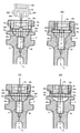
第2弁体18をピストンヘッド3の他端部に取り付ける際には、図6(a)に示すように小径凹部3bに第3バネ17を挿入し、一対の腕部18dを一対の第1縦溝3a1に正対させ、環状膨出部18cを大径凹部3aの周側面に摺接させつつ、第2弁体18を大径凹部3aに挿入し、環状溝18eを第3バネ17に当接させ、第3バネ17を押圧しつつ更に第2弁体18を大径凹部3aに押し込み、腕部18dが周溝3a2の一方の側壁に当接すると押し込みを止め、図6(b)に示すように、第2弁体18を捩じって周溝3a2に沿って中止軸線X周りに回転させる。回転時には、第2弁体18は第3バネ17の付勢力を受け、腕部18dが周溝3a2の他方の側壁に押しつけられる。第2弁体18が回転を続けて図6(c)に示すように腕部18dが第2縦溝3a3に対峙する回転位置に到達すると、第3バネ17の付勢力を受けた第2弁体18は、図6(d)に示すように、腕部18dを第2縦溝3a3に係合させつつ、ピストンヘッド3の他端へ向けて移動し、腕部18dが第2縦溝3a3の終端部に当接して停止する。前記手順で第2弁体18がピストンヘッド3の他端部に取り付けられる。ピストンヘッド3の他端部に取り付けられた第2弁体18は、中心軸線X方向に互いに間隔を隔てた、環状膨出部18cと大径凹部3aの周側面との摺接部と、腕部18dと第2縦溝3a3との係合部の2箇所で中心軸線X方向にガイドされている。
As shown in FIG. 4, the
As shown in FIG. 5, the other end of the
The
When attaching the
減圧弁1の作動を説明する。
二次側通路2bに図示しない配管を介して接続された図示しない吐水装置が閉鎖され、前記配管内の水流が停止している時は、図2に示すように、第1弁体7が第1弁座6に当接して減圧弁機構αは閉弁している。逃し弁機構βも二次側通路2bの内圧(以下二次圧と呼ぶ)が開弁圧に達していないかぎり、第3バネ17の付勢力を受けた第2弁体18のシール部材18bが第2弁座16に当接して閉弁している。第2弁体18のシール部材18bが第2弁座16に当接して逃し弁機構βが閉弁している時、第2弁体18の腕部18dは第2縦溝3a3の延在途上に在り第2縦溝3a3の終端部には当接していない。
二次側通路2bと感圧室13とは連通しているので、二次圧がダイアフラム12に印加される。一次圧はオーリング4がピストンヘッド3とシリンダ2cとの摺接部をシールすることにより、感圧室13には伝達されず、ダイアフラム12には印加されない。
前記吐水装置が開放されると、二次圧が低下し、ダイアフラム12に印加される二次圧による閉弁方向の付勢力が減少して、図1に示すように、第1弁体7が第1弁座6から離れ、減圧弁機構αは開弁する。第1弁体7と第1弁座6との間に形成された環状隙間を水道水が流れる際に圧力損失が発生し、水道水は減圧される。
減圧弁機構αの作動中に、何らかの原因で二次圧が上昇すると、第2バネ14の付勢力に抗してダイアフラム12が第1弁座6から遠ざかる方向へ弾性変形し、ダイアフラム12に固定された筒体11がピストンヘッド3から遠ざかる方向へ移動し、第1バネ8の付勢力を受けたピストンヘッド3が、ひいては第1弁体7が筒体11に追随して移動し、第1弁体7が第1弁座6に接近する。この結果、第1弁座7と第1弁体6との間の環状隙間が狭まり、前記環状隙間を水道水が通過する際の圧力損失が増加する。この結果、二次圧が下降する。従って、減圧弁機構αにより、二次圧は所定値に維持される。
減圧弁機構αの作動中、第3バネ17の付勢力を受けた第2弁体18のシール部材18bと第2弁座16との当接状態が維持され、逃し弁機構βは閉弁している。
The operation of the
When the water discharge device (not shown) connected to the
Since the
When the water discharge device is opened, the secondary pressure decreases, the urging force in the valve closing direction due to the secondary pressure applied to the
If the secondary pressure rises for some reason while the pressure reducing valve mechanism α is operating, the
During the operation of the pressure reducing valve mechanism α, the contact state between the
減圧弁機構αの作動中に、二次圧が減圧弁機構αの閉弁圧まで上昇すると、第1弁体7が第1弁座6に当接して減圧弁機構αは図2の閉弁状態になる。
二次圧が減圧弁機構αの閉弁圧を超えて更に上昇すると、ダイアフラム12が第1弁座6から遠ざかる方向へ更に弾性変形し、筒体11がピストンヘッド3から更に遠ざかる方向へ移動する。筒体11がピストンヘッド3から更に遠ざかる方向へ移動すると、第3バネ17の付勢力を受けた第2弁体18は第2弁座16との当接状態を維持して筒体11の移動に追随するが、二次圧が逃し弁機構βの開弁圧に達すると、腕部18dが第2縦溝3a3の終端部に当接して第2弁体18の逃し弁機構βの閉弁方向の移動が規制される。
二次圧が逃し弁機構βの開弁圧を超えて上昇すると、図3に示すように、ダイアフラム12の第1弁座6から遠ざかる方向への更なる弾性変形に追随してピストンヘッド3から遠ざかる方向へ移動する第2弁座16が、逃し弁機構β閉弁方向への移動が第2縦溝3a3の終端部により規制された第2弁体18のシール部材18bから離れ、逃し弁機構βが開弁し、感圧室13が、ひいては二次側通路2bが、筒状部材11の第1部分11aに形成された開口11a’と、第2弁座16と第2弁体18の間の隙間と、筒状部材11の第1部分11aと第2部分11bの中央穴と、バネケース15の内部空間と、排水筒19と、を介して外部環境に連通する。この結果、図3(b)に多数の矢印で示すように、感圧室13内、ひいては二次側通路2b内の水がバネケース15の内部空間へ流入し、排水筒19を介して外部環境に放出され、二次圧が低下して、二次側通路2bに接続された水回り機器の損傷が防止される。
When the secondary pressure rises to the valve closing pressure of the pressure reducing valve mechanism α during the operation of the pressure reducing valve mechanism α, the first valve body 7 comes into contact with the
When the secondary pressure further rises beyond the valve closing pressure of the pressure reducing valve mechanism α, the
When the secondary pressure rises beyond the valve opening pressure of the relief valve mechanism β, as shown in FIG. 3, the
減圧弁1においては、減圧弁機構αの第1弁体7は、中心軸線X方向に互いに間隔を隔てたピストンヘッド3とシリンダ2c内周面との摺接部と、第1弁体7とバネ押さえ9との摺接部の2箇所で中心軸線X方向にガイドされており、逃し弁機構βの第2弁座16は、中心軸線X方向に互いに間隔を隔てた筒体第2部分11bとバネケース筒部15aとの摺接部と、筒体第1部分11aとシリンダ2cとの摺接部の2箇所で中心軸線X方向にガイドされ、逃し弁機構βの第2弁体18は、中心軸線X方向に互いに間隔を隔てた、環状膨出部18cと大径凹部3aの周側面との摺接部と、腕部18dと第2縦溝3a3との係合部の2箇所で中心軸線Xの延在方向にガイドされているので、部品精度や組立精度の影響を受け難く、第1弁体7は減圧弁機構αの閉鎖面に対して傾かず、第2弁座16と第2弁体18は逃し弁機構βの閉鎖面に対して傾かず、減圧弁機構αのスムーズな動きや止水機能と逃し弁機構βのスムーズな動きや止水機能とに支障を来さない。腕部18dと第2縦溝3a3との係合部には僅かな遊びがあるので、第2弁体18は逃し弁機構βの閉鎖面に対して僅かに傾くことができる。従って、万一部品精度や組立精度の影響を受けて第2弁座16が逃し弁機構βの閉鎖面に対して僅かに傾いた場合でも、第2弁体18は第2弁座16に追随して第2弁座16に正対し、密着することができる。
減圧弁1においては、第3バネ17のバネ定数を小さな値に設定したので、第2弁体18のシール材18bの第2弁座16との当接部に大きな面圧が発生せず、シール材18bの経時的な性能劣化を防止できる。第2弁体18のストッパーとして機能する第2縦溝3a3を配設したので、逃し弁機構βを確実に開弁させることができる。
第1弁体7、第2弁座16、第2弁体18のそれぞれ2箇所のガイドは、第1弁体7、第2弁座16、第2弁体18のスムーズな動きと摺動抵抗低減の観点から、中心軸線X方向に可能な限り離隔させるのが望ましい。
減圧弁1においては、押して捩じるバヨネット式接続機構を配設したので、第2弁体18をピストンヘッド3の他端部に容易に取り付けることができる。
In the
In the
The two guides of the first valve body 7, the
Since the
第1弁体7をバネ押さえ9に直接摺動嵌合させるのに代えて、第1弁体7から伸ばした弁軸をバネ押さえ9の底壁から延びる筒部に摺動嵌合させても良く、或いは他の任意の構成で第1弁体7を中心軸線X方向にガイドしても良い。
第2弁座16に代えて環状の第2弁体を筒体11の一端部に配設し、第2弁体18に代えて環状の第2弁座をピストンヘッド3の他端部に配設しても良い。
有底筒状のケース18aに、開放端部の外周側面に形成した径方向への環状膨出部18cに加えて、底部の外周側面にも径方向への環状膨出部を形成し、大径凹部3aの周側面に摺接させても良い。第2弁体18の中心軸線X方向へのガイドが、より確実になる。
第2弁体18をピストンヘッド3の他端部に固定しても良い。ピストンヘッド3が互いに離隔した2箇所で中心軸線X方向にガイドされているので、ピストンヘッド3の他端部に固定された第2弁体18も互いに離隔した2箇所で中心軸線X方向にガイドされることになる。従って、第2弁体18は部品精度や組立精度の影響を受け難く、逃し弁機構βの閉鎖面に対して傾かず、逃し弁機構βのスムーズな動きや止水機能に支障を来さない。
Instead of directly sliding-fitting the first valve body 7 to the
An annular second valve body is arranged at one end of the
In addition to the radial
The
本発明は、逃し弁機構を備える減圧弁に広く利用可能である。 INDUSTRIAL APPLICABILITY The present invention can be widely used for a pressure reducing valve provided with a relief valve mechanism.
1 減圧弁
2 ボディ
2a 一次側通路
2b 二次側通路
2c シリンダ
2d ダイアフラムケース
3 ピストンヘッド
6 第1弁座
7 第1弁体
8 第1バネ
11 筒体
12 ダイアフラム
13 感圧室
14 第2バネ
15 バネケース
16 第2弁座
17 第2弁体
19 排水筒
α 減圧弁機構
β 逃し弁機構
1
Claims (5)
Priority Applications (1)
| Application Number | Priority Date | Filing Date | Title |
|---|---|---|---|
| JP2017234759A JP6996830B2 (en) | 2017-12-07 | 2017-12-07 | Pressure reducing valve |
Applications Claiming Priority (1)
| Application Number | Priority Date | Filing Date | Title |
|---|---|---|---|
| JP2017234759A JP6996830B2 (en) | 2017-12-07 | 2017-12-07 | Pressure reducing valve |
Publications (2)
| Publication Number | Publication Date |
|---|---|
| JP2019101946A JP2019101946A (en) | 2019-06-24 |
| JP6996830B2 true JP6996830B2 (en) | 2022-01-17 |
Family
ID=66977060
Family Applications (1)
| Application Number | Title | Priority Date | Filing Date |
|---|---|---|---|
| JP2017234759A Active JP6996830B2 (en) | 2017-12-07 | 2017-12-07 | Pressure reducing valve |
Country Status (1)
| Country | Link |
|---|---|
| JP (1) | JP6996830B2 (en) |
Families Citing this family (8)
| Publication number | Priority date | Publication date | Assignee | Title |
|---|---|---|---|---|
| JP7180465B2 (en) * | 2019-03-13 | 2022-11-30 | 三菱電機株式会社 | Relief valve integrated pressure reducing valve and water heater |
| JP2020195452A (en) * | 2019-05-31 | 2020-12-10 | 株式会社三洋物産 | Game machine |
| JP2020195450A (en) * | 2019-05-31 | 2020-12-10 | 株式会社三洋物産 | Game machine |
| JP2020195451A (en) * | 2019-05-31 | 2020-12-10 | 株式会社三洋物産 | Game machine |
| JP2020195449A (en) * | 2019-05-31 | 2020-12-10 | 株式会社三洋物産 | Game machine |
| JP7551514B2 (en) * | 2021-01-20 | 2024-09-17 | 株式会社ダンレイ | Pressure reducing valve |
| JP7534990B2 (en) | 2021-03-12 | 2024-08-15 | 株式会社ダンレイ | Pressure reducing valve |
| CN117287541B (en) * | 2023-11-24 | 2024-02-13 | 科讯工业制造(深圳)有限公司 | Adjustable pressure stabilizing valve, assembling method thereof and semiconductor manufacturing equipment |
Citations (1)
| Publication number | Priority date | Publication date | Assignee | Title |
|---|---|---|---|---|
| JP2013196399A (en) | 2012-03-21 | 2013-09-30 | Danrei:Kk | Pressure reducing valve |
Family Cites Families (3)
| Publication number | Priority date | Publication date | Assignee | Title |
|---|---|---|---|---|
| JPS62155383A (en) * | 1985-12-27 | 1987-07-10 | N T C Kogyo Kk | Pressure reducing and releasing valve of tubulous valve type |
| JPS6391715A (en) * | 1986-10-06 | 1988-04-22 | N T C Kogyo Kk | Reducing valve with relief valve |
| JPH044256Y2 (en) * | 1987-12-07 | 1992-02-07 |
-
2017
- 2017-12-07 JP JP2017234759A patent/JP6996830B2/en active Active
Patent Citations (1)
| Publication number | Priority date | Publication date | Assignee | Title |
|---|---|---|---|---|
| JP2013196399A (en) | 2012-03-21 | 2013-09-30 | Danrei:Kk | Pressure reducing valve |
Also Published As
| Publication number | Publication date |
|---|---|
| JP2019101946A (en) | 2019-06-24 |
Similar Documents
| Publication | Publication Date | Title |
|---|---|---|
| JP6996830B2 (en) | Pressure reducing valve | |
| US9249611B2 (en) | Rotary damper | |
| US3981479A (en) | Check valve | |
| JP2009301109A (en) | Pressure reducing valve | |
| EP3614025B1 (en) | Two-way valve | |
| EP2580503B1 (en) | Face sealing annular valve | |
| KR20190136208A (en) | Check valve | |
| WO2016136427A1 (en) | Fluid controller | |
| JP2020079643A (en) | Pressure limiting valve with horizontal characteristic line and aftersuction | |
| JP2012031966A (en) | Three-way valve | |
| JP2013196399A (en) | Pressure reducing valve | |
| JP6945932B2 (en) | Leakage detection device | |
| TWI299076B (en) | Pilot-type two-port valve | |
| JP7012367B2 (en) | Switching valve | |
| KR101885050B1 (en) | Check valve | |
| US11067194B2 (en) | Combination valve | |
| JPS628804B2 (en) | ||
| US6375154B1 (en) | Seat and holding valve | |
| JP5104617B2 (en) | Poppet type pressure reducing valve | |
| JP4801375B2 (en) | Air operated valve | |
| JP4988775B2 (en) | Hydraulic valve assembly | |
| JP2022082315A (en) | Pressure reducing valve | |
| JP7149037B2 (en) | Pressure reducing valve | |
| JP6966961B2 (en) | Control valve | |
| JP2013079692A (en) | Flow rate control valve |
Legal Events
| Date | Code | Title | Description |
|---|---|---|---|
| A621 | Written request for application examination |
Free format text: JAPANESE INTERMEDIATE CODE: A621 Effective date: 20201026 |
|
| A131 | Notification of reasons for refusal |
Free format text: JAPANESE INTERMEDIATE CODE: A131 Effective date: 20210629 |
|
| A977 | Report on retrieval |
Free format text: JAPANESE INTERMEDIATE CODE: A971007 Effective date: 20210630 |
|
| A521 | Request for written amendment filed |
Free format text: JAPANESE INTERMEDIATE CODE: A523 Effective date: 20210713 |
|
| TRDD | Decision of grant or rejection written | ||
| A01 | Written decision to grant a patent or to grant a registration (utility model) |
Free format text: JAPANESE INTERMEDIATE CODE: A01 Effective date: 20211215 |
|
| A61 | First payment of annual fees (during grant procedure) |
Free format text: JAPANESE INTERMEDIATE CODE: A61 Effective date: 20211215 |
|
| R150 | Certificate of patent or registration of utility model |
Ref document number: 6996830 Country of ref document: JP Free format text: JAPANESE INTERMEDIATE CODE: R150 |
|
| R250 | Receipt of annual fees |
Free format text: JAPANESE INTERMEDIATE CODE: R250 |
|
| R250 | Receipt of annual fees |
Free format text: JAPANESE INTERMEDIATE CODE: R250 |