JP7001032B2 - 燃料タンクの開閉装置 - Google Patents
燃料タンクの開閉装置 Download PDFInfo
- Publication number
- JP7001032B2 JP7001032B2 JP2018183221A JP2018183221A JP7001032B2 JP 7001032 B2 JP7001032 B2 JP 7001032B2 JP 2018183221 A JP2018183221 A JP 2018183221A JP 2018183221 A JP2018183221 A JP 2018183221A JP 7001032 B2 JP7001032 B2 JP 7001032B2
- Authority
- JP
- Japan
- Prior art keywords
- opening
- drainage
- port
- passage
- nozzle insertion
- Prior art date
- Legal status (The legal status is an assumption and is not a legal conclusion. Google has not performed a legal analysis and makes no representation as to the accuracy of the status listed.)
- Active
Links
- 239000002828 fuel tank Substances 0.000 title claims description 55
- 238000003780 insertion Methods 0.000 claims description 122
- 230000037431 insertion Effects 0.000 claims description 122
- 230000002093 peripheral effect Effects 0.000 claims description 41
- 239000007788 liquid Substances 0.000 claims description 38
- NJPPVKZQTLUDBO-UHFFFAOYSA-N novaluron Chemical compound C1=C(Cl)C(OC(F)(F)C(OC(F)(F)F)F)=CC=C1NC(=O)NC(=O)C1=C(F)C=CC=C1F NJPPVKZQTLUDBO-UHFFFAOYSA-N 0.000 claims description 12
- 239000000945 filler Substances 0.000 description 59
- 239000000446 fuel Substances 0.000 description 51
- 238000004891 communication Methods 0.000 description 10
- 239000011347 resin Substances 0.000 description 5
- 229920005989 resin Polymers 0.000 description 5
- 239000012530 fluid Substances 0.000 description 4
- 230000000994 depressogenic effect Effects 0.000 description 3
- 238000013461 design Methods 0.000 description 3
- 239000004952 Polyamide Substances 0.000 description 2
- 239000004734 Polyphenylene sulfide Substances 0.000 description 2
- 230000015572 biosynthetic process Effects 0.000 description 2
- 239000000470 constituent Substances 0.000 description 2
- 238000010586 diagram Methods 0.000 description 2
- 238000004519 manufacturing process Methods 0.000 description 2
- 238000000034 method Methods 0.000 description 2
- 238000012986 modification Methods 0.000 description 2
- 230000004048 modification Effects 0.000 description 2
- 238000010943 off-gassing Methods 0.000 description 2
- 229920002647 polyamide Polymers 0.000 description 2
- 229920000069 polyphenylene sulfide Polymers 0.000 description 2
- 230000002159 abnormal effect Effects 0.000 description 1
- 238000013459 approach Methods 0.000 description 1
- 238000005520 cutting process Methods 0.000 description 1
- 239000000428 dust Substances 0.000 description 1
- 230000000694 effects Effects 0.000 description 1
- 239000003502 gasoline Substances 0.000 description 1
- 230000005484 gravity Effects 0.000 description 1
- 238000009434 installation Methods 0.000 description 1
- 230000001050 lubricating effect Effects 0.000 description 1
- 239000000463 material Substances 0.000 description 1
- 238000003825 pressing Methods 0.000 description 1
- 238000009751 slip forming Methods 0.000 description 1
- 239000000758 substrate Substances 0.000 description 1
Images





Landscapes
- Cooling, Air Intake And Gas Exhaust, And Fuel Tank Arrangements In Propulsion Units (AREA)
Description
この形態の燃料タンクの開閉装置では、ハウジングが形成するノズル挿入通路から第1開口に向けて流体が流れると、この液体は、カバー本体とハウジングとの間の排液機構の排液口に到達する。そして、排液口が排液弁により開放されると、液体は、凹所を通過して、ハウジングの第1開口と対向するカバー本体の第2開口に流れる。第2開口は、ハウジングを取り囲む周壁に形成されて大気開放されていることから、第2開口まで流れた液体を、この第2開口から装置外部に支障なく排液できる。
第1開口から第2開口までの液体排液に関与する排液機構は、カバー本体とこれに組み込まれるハウジングとの間、即ちハウジングの組込領域に配設される。よって、燃料タンクの開閉装置のアウターボディーとなるカバー本体では、周壁に大気開放の第2開口が形成されていれば良く、排液通路の形成部位を装置外部に突出させて設ける必要がない。これに加え、この形態の燃料タンクの開閉装置では、排液口を開閉する排液弁を、第1開口側からノズル挿入口の中心軸側に突出して窪んだ凹所に保持片により保持する。排液弁の保持領域が第1開口側からカバー本体側に広がるほど、排液機構の組込領域はカバー本体側に広がる。この形態の燃料タンクの開閉装置では、排液弁をノズル挿入口の中心軸側に突出して窪んだ凹所に保持しているので、排液機構の組込領域の広がりを抑制できる。この結果、この形態の燃料タンクの開閉装置によれば、ノズル挿入通路に入り込んだ液体を確実に排液できるようにした上で、開閉装置のアウターボディーとなるカバー本体が装置外部に突出しないようにできる、或いは、突出の程度をより確実に抑制できる。
(2)上記形態の燃料タンクの開閉装置において、前記保持片は、前記回動軸の軸表面に向き合う湾曲面部位で、前記回動軸を保持するようにしてもよい。こうすれば、弁本体を回動軸を基点に円滑に回動させることができるので、排液性を高めることができる。
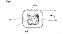
(3)上記形態の燃料タンクの開閉装置において、前記排液口形成部材は、前記回動軸が前記凹所壁の内壁面に接触しないように、前記弁本体を前記排液口の開口上端面で受け止める台座部を有するようにしてもよい。こうすれば、弁本体を回動軸を基点により一層と円滑に回動させることができるので、排液性をより高めることができる。
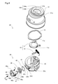
上記の実施形態では、排液弁47を、回動軸47aの軸表面に向き合う保持片48cの湾曲面部位48eで保持したが、湾曲面部位48eに代えて、V字状に窪んだ凹壁面部位で回動軸47aを保持するようにしてもよい。
11…挿入口開閉部材
11a…陥没凹所
12…挿入側スプリング
12L…固定端
15…環状体
20…開閉装置
21…アウターボディー
21a…周壁
21b…天井壁
21c…連通口
22…インナーボディー
22a…通路周壁
22b…突出壁部
22c…傾斜壁部
22d…係合突起
23…アンダーボディー
25…燃料通路形成部
30…タンク側開閉機構
31…タンク側開閉部材
32…タンク側スプリング
32L…固定端
40…排液機構
41…第1開口
42…第2開口
43…第3開口
43a…凸部
45…環状シール体
46…排液口形成部材
46a…排液口
46b…凸部
46c…凹所壁
46d…台座部
46da…溝部
46e…内周壁
47…排液弁
47a…回動軸
47b…平坦部
47c…弁本体
48…保持部材
48a…係合腕
48b…係合孔
48c…保持片
48d…排液通路
48e…湾曲面部位
100…フィラーネック
100N…ノズル挿入通路
100P…燃料通路
102…燃料蒸気ポート
104…ノズル挿入口
104s…給油口周壁
104t…ノズル挿入側周壁
BV…ガス放出弁
FE…装着部材
FN…給油ノズル
FP…フィラーパイプ
FR…給油室
FS…給油装置
FT…燃料タンク
NT…燃料蒸気チューブ
OL…中心軸
TV…逆止弁
Claims (3)
- 燃料タンクの開閉装置(20)であって、
給油ノズル(FN)のノズル挿入通路(100N)を取り囲むように形成された通路周壁(22a)と、前記通路周壁(22a)に形成されて前記ノズル挿入通路(100N)を大気開放する第1開口(41)とを有するハウジング(22)と、
前記ハウジング(22)が組み込まれるカバー本体(21)であって、前記ハウジング(22)を取り囲むように形成された周壁(21a)と、前記周壁(21a)に形成されて前記第1開口(41)と対向する大気開放の第2開口(42)とを有し、前記周壁(21a)の天井壁(21b)に前記給油ノズル(FN)のノズル挿入口(104)を有する前記カバー本体(21)と、
前記ノズル挿入口(104)を開閉する挿入口開閉機構(10)と、
前記カバー本体(21)と前記ハウジング(22)との間に位置して前記ノズル挿入通路(100N)から液体を排液する排液機構(40)とを有し、
前記排液機構(40)は、
前記第1開口(41)に装着され、前記第1開口(41)側から前記ノズル挿入口(104)の中心軸(OL)側に突出して前記第1開口(41)側で窪んだ凹所(48d)を前記第2開口(42)に連続して形成する凹所壁(46c)を有し、前記凹所壁(46c)に前記ノズル挿入通路(100N)から前記第1開口(41)に向けて流れる液体の排液口(46a)が形成された排液口形成部材(46)と、
回動軸(47a)と弁本体(47c)を有し、前記凹所(48d)において、前記回動軸(47a)を基点とした前記弁本体(47c)の回動により前記排液口(46a)を開閉する排液弁(47)と、
前記回動軸(47a)を前記凹所壁(46c)に対して保持する保持片(48c)を有する保持部材(48)とを備える、燃料タンクの開閉装置(20)。 - 請求項1に記載の燃料タンクの開閉装置(20)であって、
前記保持片(48c)は、前記回動軸(47a)の軸表面に向き合う湾曲面部位(48e)で、前記回動軸(47a)を保持する、燃料タンクの開閉装置(20)。 - 請求項1または請求項2に記載の燃料タンクの開閉装置(20)であって、
前記排液口形成部材(46)は、前記回動軸(47a)が前記凹所壁(46c)の内壁面に接触しないように、前記弁本体(47c)を前記排液口(46a)の開口上端面で受け止める台座部(46d)を有する、燃料タンクの開閉装置(20)。
Priority Applications (3)
| Application Number | Priority Date | Filing Date | Title |
|---|---|---|---|
| JP2018183221A JP7001032B2 (ja) | 2018-09-28 | 2018-09-28 | 燃料タンクの開閉装置 |
| US16/567,225 US10843555B2 (en) | 2018-09-28 | 2019-09-11 | Opening/closing device of fuel tank |
| CN201910910898.9A CN110962587B (zh) | 2018-09-28 | 2019-09-25 | 燃料箱的开闭装置 |
Applications Claiming Priority (1)
| Application Number | Priority Date | Filing Date | Title |
|---|---|---|---|
| JP2018183221A JP7001032B2 (ja) | 2018-09-28 | 2018-09-28 | 燃料タンクの開閉装置 |
Publications (2)
| Publication Number | Publication Date |
|---|---|
| JP2020050235A JP2020050235A (ja) | 2020-04-02 |
| JP7001032B2 true JP7001032B2 (ja) | 2022-01-19 |
Family
ID=69995507
Family Applications (1)
| Application Number | Title | Priority Date | Filing Date |
|---|---|---|---|
| JP2018183221A Active JP7001032B2 (ja) | 2018-09-28 | 2018-09-28 | 燃料タンクの開閉装置 |
Country Status (1)
| Country | Link |
|---|---|
| JP (1) | JP7001032B2 (ja) |
Citations (5)
| Publication number | Priority date | Publication date | Assignee | Title |
|---|---|---|---|---|
| DE202017100715U1 (de) | 2016-02-12 | 2017-03-27 | Gerdes Gmbh | Deckelloser Stutzenabschluss für einen Kraftstoffeinfüllstutzen und Kraftstoffeinfüllstutzen mit einem deckellosen Verschluss |
| JP2017114272A (ja) | 2015-12-24 | 2017-06-29 | 豊田合成株式会社 | 燃料タンクの開閉装置 |
| JP2017226278A (ja) | 2016-06-21 | 2017-12-28 | 本田技研工業株式会社 | 燃料供給管の給油部構造 |
| US20180079296A1 (en) | 2016-09-19 | 2018-03-22 | Honda Motor Co., Ltd. | Fuel filler structure of fuel supply pipe |
| JP2018090107A (ja) | 2016-12-05 | 2018-06-14 | 豊田合成株式会社 | 燃料タンクの開閉装置 |
-
2018
- 2018-09-28 JP JP2018183221A patent/JP7001032B2/ja active Active
Patent Citations (5)
| Publication number | Priority date | Publication date | Assignee | Title |
|---|---|---|---|---|
| JP2017114272A (ja) | 2015-12-24 | 2017-06-29 | 豊田合成株式会社 | 燃料タンクの開閉装置 |
| DE202017100715U1 (de) | 2016-02-12 | 2017-03-27 | Gerdes Gmbh | Deckelloser Stutzenabschluss für einen Kraftstoffeinfüllstutzen und Kraftstoffeinfüllstutzen mit einem deckellosen Verschluss |
| JP2017226278A (ja) | 2016-06-21 | 2017-12-28 | 本田技研工業株式会社 | 燃料供給管の給油部構造 |
| US20180079296A1 (en) | 2016-09-19 | 2018-03-22 | Honda Motor Co., Ltd. | Fuel filler structure of fuel supply pipe |
| JP2018090107A (ja) | 2016-12-05 | 2018-06-14 | 豊田合成株式会社 | 燃料タンクの開閉装置 |
Also Published As
| Publication number | Publication date |
|---|---|
| JP2020050235A (ja) | 2020-04-02 |
Similar Documents
| Publication | Publication Date | Title |
|---|---|---|
| US10518635B2 (en) | Fuel supply portion structure of fuel supply pipe | |
| JP4017587B2 (ja) | チェックバルブ一体型カットバルブ | |
| JP6965634B2 (ja) | 燃料タンクの開閉装置 | |
| JP2011500455A (ja) | 充填ノズルの位置決め装置 | |
| US4809865A (en) | Fuel tank for use in a vehicle | |
| JP4074113B2 (ja) | 燃料タンク用コネクタ | |
| KR101827688B1 (ko) | 연료 탱크용 체크 밸브 | |
| CN110962587B (zh) | 燃料箱的开闭装置 | |
| JP2009173149A (ja) | タンク用開閉装置 | |
| US20050051216A1 (en) | Pressure opening and closing valve | |
| US20130075399A1 (en) | Fuel tank opening-closing device | |
| JP2006044586A (ja) | 燃料タンク用チェックバルブ | |
| JP2019143580A (ja) | 燃料バルブ | |
| JP2017226279A (ja) | 燃料供給管の給油部構造 | |
| JP7001032B2 (ja) | 燃料タンクの開閉装置 | |
| JP7070297B2 (ja) | 燃料タンクの開閉装置 | |
| JP2018052380A (ja) | 給油装置 | |
| US7146729B2 (en) | Fuel vapor vent valve and method of attaching same to a tank | |
| WO2018193883A1 (ja) | 給油口構造 | |
| JP7143561B2 (ja) | 燃料タンクの開閉装置 | |
| JP7155818B2 (ja) | 燃料タンクの開閉装置 | |
| JP7115890B2 (ja) | 弁装置 | |
| JP6881339B2 (ja) | 給油装置 | |
| JP4660156B2 (ja) | 燃料逆流防止バルブ | |
| US10882393B2 (en) | Fuel supply device |
Legal Events
| Date | Code | Title | Description |
|---|---|---|---|
| A621 | Written request for application examination |
Free format text: JAPANESE INTERMEDIATE CODE: A621 Effective date: 20201028 |
|
| A977 | Report on retrieval |
Free format text: JAPANESE INTERMEDIATE CODE: A971007 Effective date: 20210927 |
|
| A131 | Notification of reasons for refusal |
Free format text: JAPANESE INTERMEDIATE CODE: A131 Effective date: 20211012 |
|
| A521 | Written amendment |
Free format text: JAPANESE INTERMEDIATE CODE: A523 Effective date: 20211110 |
|
| TRDD | Decision of grant or rejection written | ||
| A01 | Written decision to grant a patent or to grant a registration (utility model) |
Free format text: JAPANESE INTERMEDIATE CODE: A01 Effective date: 20211124 |
|
| A61 | First payment of annual fees (during grant procedure) |
Free format text: JAPANESE INTERMEDIATE CODE: A61 Effective date: 20211207 |
|
| R150 | Certificate of patent or registration of utility model |
Ref document number: 7001032 Country of ref document: JP Free format text: JAPANESE INTERMEDIATE CODE: R150 |