JP7008043B2 - Module for internal energy control of converter - Google Patents
Module for internal energy control of converter Download PDFInfo
- Publication number
- JP7008043B2 JP7008043B2 JP2018566832A JP2018566832A JP7008043B2 JP 7008043 B2 JP7008043 B2 JP 7008043B2 JP 2018566832 A JP2018566832 A JP 2018566832A JP 2018566832 A JP2018566832 A JP 2018566832A JP 7008043 B2 JP7008043 B2 JP 7008043B2
- Authority
- JP
- Japan
- Prior art keywords
- converter
- power
- voltage
- arm
- internal energy
- Prior art date
- Legal status (The legal status is an assumption and is not a legal conclusion. Google has not performed a legal analysis and makes no representation as to the accuracy of the status listed.)
- Active
Links
Images


Classifications
-
- H—ELECTRICITY
- H02—GENERATION; CONVERSION OR DISTRIBUTION OF ELECTRIC POWER
- H02M—APPARATUS FOR CONVERSION BETWEEN AC AND AC, BETWEEN AC AND DC, OR BETWEEN DC AND DC, AND FOR USE WITH MAINS OR SIMILAR POWER SUPPLY SYSTEMS; CONVERSION OF DC OR AC INPUT POWER INTO SURGE OUTPUT POWER; CONTROL OR REGULATION THEREOF
- H02M7/00—Conversion of AC power input into DC power output; Conversion of DC power input into AC power output
- H02M7/42—Conversion of DC power input into AC power output without possibility of reversal
- H02M7/44—Conversion of DC power input into AC power output without possibility of reversal by static converters
- H02M7/48—Conversion of DC power input into AC power output without possibility of reversal by static converters using discharge tubes with control electrode or semiconductor devices with control electrode
- H02M7/483—Converters with outputs that each can have more than two voltages levels
-
- H—ELECTRICITY
- H02—GENERATION; CONVERSION OR DISTRIBUTION OF ELECTRIC POWER
- H02M—APPARATUS FOR CONVERSION BETWEEN AC AND AC, BETWEEN AC AND DC, OR BETWEEN DC AND DC, AND FOR USE WITH MAINS OR SIMILAR POWER SUPPLY SYSTEMS; CONVERSION OF DC OR AC INPUT POWER INTO SURGE OUTPUT POWER; CONTROL OR REGULATION THEREOF
- H02M1/00—Details of apparatus for conversion
- H02M1/0067—Converter structures employing plural converter units, other than for parallel operation of the units on a single load
-
- H—ELECTRICITY
- H02—GENERATION; CONVERSION OR DISTRIBUTION OF ELECTRIC POWER
- H02M—APPARATUS FOR CONVERSION BETWEEN AC AND AC, BETWEEN AC AND DC, OR BETWEEN DC AND DC, AND FOR USE WITH MAINS OR SIMILAR POWER SUPPLY SYSTEMS; CONVERSION OF DC OR AC INPUT POWER INTO SURGE OUTPUT POWER; CONTROL OR REGULATION THEREOF
- H02M7/00—Conversion of AC power input into DC power output; Conversion of DC power input into AC power output
- H02M7/003—Constructional details, e.g. physical layout, assembly, wiring or busbar connections
-
- H—ELECTRICITY
- H02—GENERATION; CONVERSION OR DISTRIBUTION OF ELECTRIC POWER
- H02M—APPARATUS FOR CONVERSION BETWEEN AC AND AC, BETWEEN AC AND DC, OR BETWEEN DC AND DC, AND FOR USE WITH MAINS OR SIMILAR POWER SUPPLY SYSTEMS; CONVERSION OF DC OR AC INPUT POWER INTO SURGE OUTPUT POWER; CONTROL OR REGULATION THEREOF
- H02M7/00—Conversion of AC power input into DC power output; Conversion of DC power input into AC power output
- H02M7/42—Conversion of DC power input into AC power output without possibility of reversal
- H02M7/44—Conversion of DC power input into AC power output without possibility of reversal by static converters
- H02M7/48—Conversion of DC power input into AC power output without possibility of reversal by static converters using discharge tubes with control electrode or semiconductor devices with control electrode
- H02M7/483—Converters with outputs that each can have more than two voltages levels
- H02M7/4835—Converters with outputs that each can have more than two voltages levels comprising two or more cells, each including a switchable capacitor, the capacitors having a nominal charge voltage which corresponds to a given fraction of the input voltage, and the capacitors being selectively connected in series to determine the instantaneous output voltage
-
- H—ELECTRICITY
- H02—GENERATION; CONVERSION OR DISTRIBUTION OF ELECTRIC POWER
- H02M—APPARATUS FOR CONVERSION BETWEEN AC AND AC, BETWEEN AC AND DC, OR BETWEEN DC AND DC, AND FOR USE WITH MAINS OR SIMILAR POWER SUPPLY SYSTEMS; CONVERSION OF DC OR AC INPUT POWER INTO SURGE OUTPUT POWER; CONTROL OR REGULATION THEREOF
- H02M7/00—Conversion of AC power input into DC power output; Conversion of DC power input into AC power output
- H02M7/42—Conversion of DC power input into AC power output without possibility of reversal
- H02M7/44—Conversion of DC power input into AC power output without possibility of reversal by static converters
- H02M7/48—Conversion of DC power input into AC power output without possibility of reversal by static converters using discharge tubes with control electrode or semiconductor devices with control electrode
- H02M7/493—Conversion of DC power input into AC power output without possibility of reversal by static converters using discharge tubes with control electrode or semiconductor devices with control electrode the static converters being arranged for operation in parallel
-
- H—ELECTRICITY
- H02—GENERATION; CONVERSION OR DISTRIBUTION OF ELECTRIC POWER
- H02M—APPARATUS FOR CONVERSION BETWEEN AC AND AC, BETWEEN AC AND DC, OR BETWEEN DC AND DC, AND FOR USE WITH MAINS OR SIMILAR POWER SUPPLY SYSTEMS; CONVERSION OF DC OR AC INPUT POWER INTO SURGE OUTPUT POWER; CONTROL OR REGULATION THEREOF
- H02M1/00—Details of apparatus for conversion
- H02M1/0003—Details of control, feedback or regulation circuits
- H02M1/0009—Devices or circuits for detecting current in a converter
Landscapes
- Engineering & Computer Science (AREA)
- Power Engineering (AREA)
- Rectifiers (AREA)
- Inverter Devices (AREA)
Description
本発明は、交流(AC)を直流(DC)に変換し、その逆に変換するモジュラマルチレベルコンバータ(MMC)の技術分野に関する。 The present invention relates to the technical field of a modular multi-level converter (MMC) that converts alternating current (AC) to direct current (DC) and vice versa.
より正確には、本発明は、電力を伝送するためにDCを使用したステーションがモジュラマルチレベルコンバータを組み込まれた高電圧直流(HVDC)搬送ネットワークに関する。 More precisely, the present invention relates to a high voltage direct current (HVDC) carrier network in which a station using DC to transmit power incorporates a modular multi-level converter.
図1において、先行技術のモジュラマルチレベルコンバータ10のサブモジュールセット6を示す図を見ることができる。三相入力/出力(三相φa、φb及びφcを有する)の場合、コンバータ10は、図1の様々な構成要素に対する添え字a、b、及びcによって参照される3つの変換脚を有する。各変換脚は、上側アーム及び下側アーム(上側の指標は「u」、下側の指標「l」によって指定される)を備え、それぞれ、DC電源ネットワークの端子DC+又はDC-をAC電源ネットワークの端子に接続する。特に、各変換脚は、三相ラインφa、φb及びφcのうちの一つと、AC電源ネットワークとに接続される。図1は、各アームが電流ixiを流すサブモジュールセット6を示す(xによってアームが上側か下側かを指し、指標iが脚を指している)。また、各アームは、所望のシーケンスで制御され得る複数のサブモジュールSMxij(xはアームが上側か下側かを指し、iはアームが関連付けられる相ラインを指し、jはアーム内の直列のサブモジュールの中からのサブモジュールの番号である)を含む。この例では、1つのアームにつき3つのサブモジュールのみが示されている。実際には、それぞれ上側アーム又は下側アームは、数十から数百の範囲内でN個のサブモジュールを有していてもよい。それぞれのサブモジュールSMxijは、サブモジュールの端子間にキャパシタを選択的に直列に接続する、又はそれをバイパスするための制御部材を有する少なくとも1つのキャパシタのようなエネルギー蓄積システムを含む。サブモジュールは、複数の電圧レベルを供給するために、コンバータ10のアームに直列に接続されるエネルギー蓄積素子の数を徐々に変化させるように選択されるシーケンスで制御される。また、図1において、VdcはコンバータがDC電源ネットワークに接続される点の両端の電圧を示し、これらの点は「共通結合点」(PCC)として当業者に知られている。idcはDC電源ネットワークの電流を示し、同時に電流iga,igb及びigcは、三相ラインφa、φb及びφcによって運ばれる。また、各アームは、インダクタンスLarmを有し、それぞれの位相ラインφa、φb及びφcは、インダクタンスLfと抵抗Rfを有する。
In FIG. 1, a diagram showing a submodule set 6 of the prior art modular
図2は、図1のコンバータ10の一部を構成する先行技術のサブモジュールSMxijを示す。このサブモジュールでは、各制御部材は、電気エネルギー蓄積素子、具体的にはキャパシタCSMと直列に接続された絶縁ゲートバイポーラトランジスタ(IGBT)などの第1の電子スイッチ素子T1を含む。この第1のスイッチ素子T1とこのキャパシタCSMは、同様にIGBTである第2の電子スイッチ素子T2と並列に接続される。この第2の電子スイッチ素子T2は、サブモジュールSMxijの入力端子と出力端子の間に接続される。図2に示すように、第1のスイッチ素子T1と第2のスイッチ素子T2の両方が、それぞれの逆並列のダイオードによって接続されている。
FIG. 2 shows a prior art submodule SM xij that constitutes part of the
動作において、サブモジュールは、2つの制御状態を占有するように制御され得る。 In operation, the submodule may be controlled to occupy two control states.
「オン」状態と称される第1の状態において、第1のスイッチ素子T1及び第2のスイッチ素子T2は、エネルギー蓄積素子CSMを他のサブモジュールと直列に接続するように構成される。「オフ」状態と称される第2の状態において、第1のスイッチ素子T1及び第2のスイッチ素子T2は、エネルギー蓄積素子CSMを短絡するように構成される。 In a first state referred to as an "on" state, the first switch element T1 and the second switch element T2 are configured to connect the energy storage element CSM in series with other submodules. In a second state, referred to as the "off" state, the first switch element T1 and the second switch element T2 are configured to short-circuit the energy storage element CSM .
端子間に電圧vmを有する各アームは、オンであるサブモジュールの数に依存するデューティファクタを有する端子間に電圧Vmを有するモデル化された電圧源と、電圧源に接続されたモデル化されたキャパシタCtotによってモデル化できることが知られている。このモデルは、図3に図式的に示され、ここで、得られたモデルと共に電流iを通すアームが見られる。モデル化されたキャパシタCtotの等価キャパシタンスの逆数は、オンであるモジュールのキャパシタンスの逆数の和に等しく、次のようになる。

このように、モデル化されたキャパシタCtotの端子間の電圧vcΣは、アーム内のサブモジュールのキャパシタの端子間の電圧vcjの合計に等しい(jは1~Nの範囲にあり、キャパシタの数、すなわち、サブモジュールの数を与える)。また、各キャパシタCtotは、電流imを流す。本出願では、適当でない言葉の使い方ではあるが、Ctotはモデル化されたキャパシタ及びそのキャパシタンスの両方を指す。エネルギー蓄積素子の数が徐々に変化させるように直列に接続されたサブモジュールのオン/オフをシーケンス制御することによって、モデル化されたキャパシタCtotのエネルギー、すなわち、それぞれのモデル化された電圧源の端子間の電圧を減少又は増加させることできる。 Thus, the voltage v cΣ between the terminals of the modeled capacitor C tot is equal to the sum of the voltages v cj between the terminals of the capacitors of the submodule in the arm (j is in the range 1-N and the capacitor. Gives the number of, i.e., the number of submodules). Further, each capacitor C tot carries a current im. In this application, C tot refers to both the modeled capacitor and its capacitance, albeit in an inappropriate way of using the term. By sequence-controlling the on / off of submodules connected in series so that the number of energy storage elements gradually changes, the energy of the modeled capacitor C tot , that is, each modeled voltage source. The voltage between the terminals of can be reduced or increased.
先行技術においては、図4に示すようなMMC10のサブモジュールのセット6に相当する構成が見出されている。この図では、コンバータは、図1を参照して説明したコンバータに類似したコンバータであり、各アームをそのモデルによって置き換えられたものである。また、AC電源ネットワークの各相ラインは、電流igi及び電圧vgiに関連付けられる(ここで、指標iは、脚の数を指す)。
In the prior art, a configuration corresponding to a set 6 of submodules of the
この例では、それぞれのモデル化された電圧源は、その端子間に電圧vmxiを有し、それぞれのモデル化されたキャパシタCtotは、電流imxiを通し、その端子間に電圧vcΣxiを有する(ここで、xはアームが上側か下側かを指し、iは脚の数を指す)。また、MMCを仮想的なAC部分と仮想的なDC部分(入力端子又は出力端子において、コンバータがACエネルギーをDCエネルギーに変換するように構成されるか、又はその逆になるかに応じて)に細分化することが可能であり、サブモジュールのキャパシタに蓄えられる総エネルギーの変動は、コンバータに入力する電力とコンバータから出力する電力との間の差に等しい。 In this example, each modeled voltage source has a voltage v mxi between its terminals, and each modeled capacitor C tot passes a current imxi and a voltage v c Σxi between its terminals. Has (where x refers to whether the arm is on the upper or lower side and i refers to the number of legs). Also, the MMC is a virtual AC part and a virtual DC part (depending on whether the converter is configured to convert AC energy to DC energy at the input or output terminals, or vice versa). The fluctuation of the total energy stored in the capacitor of the submodule is equal to the difference between the power input to the converter and the power output from the converter.
このタイプのMMCでは、サブモジュールのキャパシタに蓄えられた内部エネルギーが、DC電源ネットワークの電圧から切り離されることが知られている。これにより、MMCのキャパシタに蓄えられた内部エネルギーを独立して調整することができる。これは、特に、MMCが、電源ネットワークへ、又は電源ネットワークからエネルギーを伝送又は抽出することによって、関連するDC及びAC電源ネットワークの安定化に寄与することを可能にする。 In this type of MMC, it is known that the internal energy stored in the capacitor of the submodule is separated from the voltage of the DC power supply network. This makes it possible to independently adjust the internal energy stored in the MMC capacitor. This allows, in particular, the MMC to contribute to the stabilization of the associated DC and AC power networks by transmitting or extracting energy to or from the power network.
従って、DC及び/又はAC電源ネットワークとMMCとの間の電力の交換は、コンバータのキャパシタに蓄積される内部エネルギーの増加又は減少につながることが理解できる。 Therefore, it can be understood that the exchange of power between the DC and / or AC power network and the MMC leads to an increase or decrease in the internal energy stored in the capacitor of the converter.
コンバータの内部エネルギーは、DC及びAC電源ネットワークの安定性に影響を及ぼす。また、DC及びAC電源ネットワークとの間の電力の交換の結果として、コンバータのキャパシタの総電圧が発振を引き起してしまうことが知られている。これらの発振は、コンバータの動作制約に従わないことによって、コンバータの適切な動作を脅かす結果を有する。先行技術の解決策は、これらの発振については考慮に入れられておらず、それによってコンバータを損傷する危険性がある。これらの解決策は、コンバータの内部エネルギーの制御に関してMMCの能力を十分に利用することを可能にしない。 The internal energy of the converter affects the stability of the DC and AC power networks. It is also known that the total voltage of the converter's capacitor causes oscillation as a result of power exchange between the DC and AC power networks. These oscillations have the consequence of threatening the proper operation of the converter by not complying with the operational constraints of the converter. Prior art solutions do not take into account these oscillations, which risks damaging the converter. These solutions do not make it possible to take full advantage of the MMC's ability to control the internal energy of the converter.
本発明の目的は、上述の問題を解決し、MMCのポテンシャルを十分に利用することが可能なモジュラマルチレベルコンバータ(MMC)を提案することである。 An object of the present invention is to propose a modular multi-level converter (MMC) capable of solving the above-mentioned problems and fully utilizing the potential of MMC.
これを行うために、本発明は、AC電圧をDC電圧に変換するための、及びその逆のコンバータであって、AC電源ネットワークに接続するためのDC部分と、AC電源ネットワークに接続するためのAC部分とを備え、コンバータは、複数の脚を備え、それぞれの脚は、上側アーム及び下側アームを備え、それぞれのアームは、各サブモジュールに特有の制御部材によって個々に制御可能な複数のサブモジュールを備え、それぞれのサブモジュールが、各サブモジュールの制御部材が「オン」状態にあるときにアーム内で直列に接続可能なキャパシタを備えることを特徴とするモジュラマルチレベル電圧コンバータを提供する。 To do this, the present invention is a converter for converting an AC voltage to a DC voltage and vice versa, for connecting a DC portion for connecting to an AC power network and connecting to an AC power network. With an AC portion, the converter has multiple legs, each leg having an upper arm and a lower arm, each arm having a plurality of individually controllable by control members specific to each submodule. Provided is a modular multi-level voltage converter comprising submodules, each submodule comprising a capacitor that can be connected in series in an arm when the control member of each submodule is in the "on" state. ..
コンバータの一般的な特徴によれば、コンバータは、コンバータの上側アーム又は下側アームのサブモジュールのキャパシタに蓄えられた内部エネルギーを調整するように構成された制御モジュールを含み、制御モジュールは、DC電源ネットワーク及びAC電源ネットワーク上で測定されたパラメータをコンバータの動作電力の設定値と共に使用することによって、内部エネルギーを上限より小さく及び/又は下限より大きくなるように制限するのに適している。 According to the general characteristics of the converter, the converter includes a control module configured to regulate the internal energy stored in the capacitors of the submodules of the upper or lower arm of the converter, where the control module is DC. By using the parameters measured on the power supply network and the AC power supply network together with the setting value of the operating power of the converter, it is suitable to limit the internal energy to be smaller than the upper limit and / or larger than the lower limit.
好ましくは、非限定的に、サブモジュールは、サブモジュールを「オン」状態又は「オフ」状態に置くことが望まれるかどうかに応じて、サブモジュールのキャパシタを関連するアームと直列に接続するかしないかのように働く2つの絶縁ゲートバイポーラトランジスタ(IGBT)によって制御される。 Preferably, without limitation, the submodule connects the capacitor of the submodule in series with the associated arm, depending on whether it is desired to put the submodule in an "on" or "off" state. It is controlled by two isolated gate bipolar transistors (IGBTs) that act as if they were not.
各アームは、キャパシタンスのモデル化されたキャパシタCtotと並列に関連付けられたモデル化された電圧源によってモデル化することができる。アームのサブモジュールのキャパシタの電圧の合計は、モデル化された電圧源と並列に接続されたモデル化されたキャパシタの端子間の電圧はvcΣに等しくなるようにvcΣと書き込まれる。さらに、モデル化された電圧源は、アームに挿入されている「挿入(inserted)」電圧とも呼ばれるその端子間の電圧vmを有し、制御されたサブモジュールの数に依存するデューティファクタによって特徴付けられる。 Each arm can be modeled by a modeled voltage source associated in parallel with the capacitance modeled capacitor C tot . The total voltage of the capacitors in the submodule of the arm is written as v cΣ so that the voltage between the terminals of the modeled capacitor connected in parallel with the modeled voltage source is equal to v c Σ . In addition, the modeled voltage source has a voltage v m between its terminals, also called the "inserted" voltage inserted into the arm, characterized by a duty factor that depends on the number of controlled submodules. Attached.
好ましくは、モデル化された電圧源に関連するデューティファクタαは、次式から計算される。

内部エネルギーの上記下限及び/又は上限は、コンバータのサブモジュールのキャパシタに蓄えられた内部エネルギーを、コンバータの適切な動作に適したレベルに保つように決定されることが理解できる。これは、コンバータの損傷を回避するのに役立ち、コンバータの能力を完全に利用することを可能にする。 It can be seen that the lower and / or upper limits of the internal energy are determined to keep the internal energy stored in the capacitors of the converter submodule at a level suitable for proper operation of the converter. This helps to avoid damage to the converter and allows you to fully utilize the power of the converter.
本発明の範囲を逸脱することなく、制御モジュールは、内部エネルギーを、上限未満にのみ、下限を超えてのみ、又は実際に上限と下限との間に調節するように構成されてもよい。 Without departing from the scope of the invention, the control module may be configured to adjust the internal energy only below the upper limit, only above the lower limit, or actually between the upper and lower limits.
また、内部エネルギーの下限及び/又は上限は、キャパシタの合計電圧における変動を考慮するように選択することができる。従って、これらの避けられない変動であるにもかかわらず、内部エネルギーは、コンバータの動作が妨げられないように、制御モジュールによって下限より上及び/又は上限より下になるように維持される。 Also, the lower and / or upper limits of the internal energy can be selected to take into account variations in the total voltage of the capacitor. Therefore, despite these unavoidable fluctuations, the internal energy is maintained above and / or below the upper limit by the control module so as not to interfere with the operation of the converter.
好ましくは、内部エネルギーの下限は、挿入された電圧Vmに関して満たすべき条件から決定される。特に、コンバータの適切な動作を保証するために、アームに挿入される挿入電圧Vmは、そのアーム内のサブモジュールの電圧の合計vcΣによって物理的に制限される。従って、この物理的制約を満たすために、挿入された電圧設定点v*
mは、すべての瞬間tにおいて、以下の不等式を満たさなければならない。

本発明の制御モジュールは、キャパシタの全電圧に対する振動ピークの場合でさえ、この不等式に適合するように内部エネルギーを調整することを可能にする。 The control module of the present invention makes it possible to adjust the internal energy to fit this inequality, even in the case of vibration peaks with respect to the total voltage of the capacitor.
また、好ましくは、内部エネルギーの上限は、サブモジュールのスイッチ素子の電圧限界から決定される。特に、コンバータの適切な動作を保証するために、サブモジュールのキャパシタにかかる電圧vcjは、各瞬間tにおいて、次式によって与えられるように、サブモジュールのスイッチ素子の電圧限界に対応する最大電圧vcMax未満でなければならない。
![]()
![]()
![]()
![]()
特に、スイッチ素子に対するこの電圧限界は、「安全電圧限界(safe voltage limit)」と呼ばれる安全マージンを与える。 In particular, this voltage limit for the switch element provides a safety margin called the "safe voltage limit".
内部エネルギーが上限又は下限に達すると、制御モジュールは、内部エネルギーをそれぞれ上限未満又は下限を超えるように戻すように補正する。 When the internal energy reaches the upper limit or the lower limit, the control module corrects the internal energy to return below the upper limit or above the lower limit, respectively.
DC電源ネットワーク及びAC電源ネットワーク上で測定されたパラメータを使用することにより、制御モジュールは、DC電源ネットワーク及びAC電源ネットワークの状態にそれ自体を適合させることによって、内部エネルギーの下限及び/又は上限を決定する。下限及び/又は上限は一定ではなく、電源ネットワークの状態によって変化することが理解できる。 By using the parameters measured on the DC and AC power networks, the control module sets the lower and / or upper limits of internal energy by adapting itself to the state of the DC and AC power networks. decide. It can be understood that the lower limit and / or the upper limit are not constant and change depending on the state of the power supply network.
好ましくは、非限定的に、これらのパラメータは、下限及び/又は上限がリアルタイムでサーボ制御され、各瞬間における電源ネットワークの状態に適合されるように、電源ネットワーク上でリアルタイムで測定される。この好ましい実施形態の利点は、決定された限界の精度を特に改善し、それによってコンバータを損傷する危険性を低減することである。 Preferably, but not limitedly, these parameters are measured in real time on the power network so that the lower and / or upper limits are servo controlled in real time and adapted to the state of the power network at each moment. The advantage of this preferred embodiment is that it particularly improves the accuracy of the determined limits, thereby reducing the risk of damaging the converter.
また、コンバータの動作電力設定値を使用することにより、同様に、コンバータの動作点を考慮して、下限及び/又は上限を決定することが可能になる。このようにして、内部エネルギー及び内部エネルギーを貯蔵するコンバータの能力がより良好に制御され、それによってMMCのポテンシャルをより多く利用する。 Further, by using the operating power setting value of the converter, it is possible to similarly determine the lower limit and / or the upper limit in consideration of the operating point of the converter. In this way, the internal energy and the ability of the converter to store the internal energy are better controlled, thereby making more use of the potential of the MMC.
有利な態様では、DC電源ネットワーク及びAC電源ネットワーク上で測定されるパラメータは、AC電源ネットワーク上で測定される電圧値vg及びDC電源ネットワーク上で測定される電圧値Vdcを含む。vgとVdcは、AC電源回路ネットワーク及びDC電源回路ネットワークの動作状態をそれぞれ表す。 In an advantageous embodiment, the parameters measured on the DC power network and the AC power network include the voltage value vg measured on the AC power network and the voltage value V dc measured on the DC power network. vg and V dc represent the operating states of the AC power supply circuit network and the DC power supply circuit network, respectively.
好ましくは、コンバータの動作電力の設定点は、有効AC電力設定点P* ac、無効AC電力設定点Q* ac、及びDC電力設定点P* dcを含む。設定点は、電力に関してコンバータの動作点を表す。 Preferably, the converter operating power setting points include an active AC power setting point P * ac , an invalid AC power setting point Q * ac , and a DC power setting point P * dc . The set point represents the operating point of the converter with respect to power.
有利な態様では、制御モジュールは、DC電源ネットワーク上及びAC電源ネットワーク上で測定されたパラメータの関数として、またコンバータの動作電力の設定値の関数として、中間変数を計算するように構成される。非限定的な方法では、数学的分析を使用して、中間変数をパラメータ及び電力設定点に関連付ける数学的関係を決定することができる。好ましくは、数学的分析を簡略化するために、制御モジュールは、設定点が関連付けられる実数値を近似するのに十分に速い制御ループであると仮定する。 In an advantageous embodiment, the control module is configured to calculate intermediate variables as a function of parameters measured on the DC and AC power networks and as a function of the converter's operating power settings. In a non-limiting method, mathematical analysis can be used to determine the mathematical relationships that associate intermediate variables with parameters and power setting points. Preferably, to simplify the theory, the control module is assumed to be a control loop that is fast enough to approximate the real value to which the setpoints are associated.
有利には、中間変数は、定常条件下でのDC電源ネットワークの電流に対する平衡三相システムにおける一相の寄与を表す等価差動電流変数Idiffを含み、これは、以下の関数によって決定される。

好ましくは、中間変数は等価差動電圧変数Vdiffを含み、この等価差動電圧変数は、定常状態におけるコンバータのDC部分の端子間の電圧を表し、関数によって決定される。

有利な態様では、中間変数は、定常条件下でAC電力供給ネットワークに流れる電流を表す等価中間電流変数Igを含む。

好ましくは、中間変数は、AC電源ネットワークの電圧ベクトルとAC電源ネットワークに流れる電流のベクトルとの間の位相差に対する位相変数θも含む。また、θは、以下から決定することができる。
![]()
![]()
![]()
![]()
有利には、中間変数は、定常条件下でのAC電源ネットワークの電圧ベクトルと、定常条件下でのコンバータによって合成された等価AC内部電圧のベクトルとの間の位相差を表す中間角度変数δを含み、δは、以下の関数によって決定される。
![]()
![]()
非限定的な方法で、我々は、Req=Rf+Rarm/2とXeq=Xf+Xarm/2=ωLf+ωLarm/2と記載し、ここで、Larm及びRarmを指定し、一方で、LfとRfは、位相ライン内のインダクタンス及び抵抗をそれぞれ示し、ωは、角周波数である。 In a non-limiting way, we write R eq = R f + R arm / 2 and X eq = X f + X arm / 2 = ωL f + ωL arm / 2, where we specify L arm and R arm . On the other hand, L f and R f indicate the inductance and resistance in the phase line, respectively, and ω is the angular frequency.
好ましくは、中間変数は、定常条件下で以下の関数によってコンバータによって合成される等価AC内部電圧変数Vvを含む。

本発明の特に有利な態様において、制御モジュールは、コンバータの上アームのキャパシタに蓄えられた内部エネルギーの振動成分WΣ
ru(t)を以下の関数によって決定するように構成される。
![]()
![]()
また、上腕における内部エネルギーは、その上腕における内部エネルギーの振動成分WΣ ru(t)と、その腕における内部エネルギーの経時的平均との和として表すことができる。 Further, the internal energy in the upper arm can be expressed as the sum of the vibration component W Σ ru (t) of the internal energy in the upper arm and the time-dependent average of the internal energy in the arm.
変形例では、制御モジュールは、以下の関数によって、コンバータの上アームのキャパシタに蓄積された内部エネルギーの振動成分WΣ
ru(t)を決定するように構成される。
![]()
![]()
有利な態様では、制御モジュールは、コンバータの上側アームのサブモジュールのキャパシタに蓄積された内部エネルギーの振動成分WΣ
Lminuを、以下の関数によって決定するように構成される。
![]()

![]()
![]()
![]()
![]()
![]()
変形例では、制御モジュールは、コンバータの下側アームのサブモジュールのキャパシタに蓄積された内部エネルギーの下限WΣ Lminlを決定するように構成される。当該下限WΣ Lminlに関する式は、上アームと下アームとの間の対称性を使用することによって決定することができる。この式では、制約の値は、上腕に適用される制約の値と同一である。 In the modified example, the control module is configured to determine the lower limit W Σ Lminl of the internal energy stored in the capacitor of the submodule of the lower arm of the converter. The equation for the lower limit W Σ Lminl can be determined by using the symmetry between the upper arm and the lower arm. In this equation, the value of the constraint is the same as the value of the constraint applied to the upper arm.
本発明の範囲を逸脱することなく、上側アーム又は下側アームのキャパシタに蓄積される内部エネルギーの下限は、瞬間tmに到達する最も好ましくない構成を考慮するアプローチを使用することによって決定することができ、このアプローチでは、以下の式が満たされる。

この好ましくない構成では、上アーム又は下アームの内部エネルギーは下限に達する。 In this unfavorable configuration, the internal energy of the upper or lower arm reaches the lower limit.
有利には、制御モジュールは、コンバータの上側アームのサブモジュールのキャパシタに蓄えられた内部エネルギーの上限WΣ
Lmaxuを、以下の関数によって決定するように構成される。


変形例では、制御モジュールは、コンバータの下側アームのサブモジュールのキャパシタに蓄積された内部エネルギーの下限WΣ Lmaxlを決定するように構成される。再び、当該下限WΣ Lmaxlに関する式は、上アームと下アームとの間の対称性を使用することによって決定することができる。この式では、制約の値は、上腕に適用される制約の値と同一である。 In the modified example, the control module is configured to determine the lower limit W Σ Lmaxl of the internal energy stored in the capacitor of the submodule of the lower arm of the converter. Again, the equation for the lower limit W Σ Lmaxl can be determined by using the symmetry between the upper arm and the lower arm. In this equation, the value of the constraint is the same as the value of the constraint applied to the upper arm.
本発明の範囲を逸脱することなく、上側又は下側アームのサブモジュールのキャパシタに蓄積される内部エネルギーの下限は、瞬間trに到達する最も好ましくない構成を考慮するアプローチを使用することによって決定することができ、その場合、以下の式が満たされる。
![]()
![]()
この好ましくない構成では、上アーム又は下アームの内部エネルギーは、内部エネルギーの上限に達する。 In this unfavorable configuration, the internal energy of the upper or lower arm reaches the upper limit of the internal energy.
好ましくは、制御モジュールは、AC電源ネットワーク上で測定される電圧値vg、DC電源ネットワーク上で測定される電圧値Vdc、有効AC電力設定点P* ac、無効AC電力設定点X* ac、及びDC電力設定点P* dcの関数として、上アーム又は下アームのサブモジュールのキャパシタに蓄積される内部エネルギーの下限及び上限を決定するための決定モジュールを含む。 Preferably, the control module has a voltage value v g measured on the AC power network, a voltage value V dc measured on the DC power network, an active AC power setting point P * ac , and an invalid AC power setting point X * ac . , And, as a function of the DC power setting point P * dc , includes a determination module for determining the lower and upper limits of the internal energy stored in the capacitor of the upper arm or lower arm submodule.
決定モジュールによって、内部エネルギーの下限及び/又は上限が、好ましくはリアルタイムで、電源ネットワークの状態の関数としてサーボ制御される。 The determination module servo-controls the lower and / or upper limits of the internal energy, preferably in real time, as a function of the state of the power network.
また好ましくは、制御モジュールは、制御モジュールによって供給されるように、上限及び下限の関数として内部エネルギー設定値を補正するための補正モジュールを含む。1つの利点は、ネットワークの状態に適合され、コンバータの適切な動作を保証する内部エネルギー設定点を得ることである。キャパシタに蓄えられた内部エネルギーの設定値のこの補正は、内部エネルギーの制御を改善し、コンバータのエネルギー蓄積能力の管理をさらに改善するのに役立つ。 Also preferably, the control module includes a correction module for correcting the internal energy set value as a function of the upper and lower limits, as supplied by the control module. One advantage is to obtain an internal energy setting point that is adapted to the state of the network and ensures proper operation of the converter. This correction of the set value of the internal energy stored in the capacitor helps to improve the control of the internal energy and further improve the management of the energy storage capacity of the converter.
従って、補正モジュールへの内部エネルギー設定値入力が下限又は上限を超えない限り、内部エネルギー設定値は変更されないことが理解できる。次いで、補正モジュールは、入力として受信された設定値と同一である内部エネルギー設定値を出力として供給する。 Therefore, it can be understood that the internal energy set value is not changed unless the input of the internal energy set value to the correction module exceeds the lower limit or the upper limit. The correction module then supplies an internal energy set value, which is the same as the set value received as an input, as an output.
対照的に、内部エネルギー設定点が下限より低いか、又は上限より高い場合、補正モジュールは、設定点が下限より高いか、又は上限より低くなるように設定点を補正する。 In contrast, if the internal energy set point is below the lower limit or higher than the upper limit, the correction module corrects the set point so that the set point is higher than the lower limit or lower than the upper limit.
本発明の特に有利な態様では、制御モジュールは、コンバータの内部エネルギーを調整し、入力としてコンバータの内部エネルギー設定値を有し、コンバータのキャパシタの電力設定値を供給するためのレギュレータを含む。この内部エネルギーレギュレータは、コンバータの上アーム又は下アームのキャパシタに蓄えられた内部エネルギーを、コンバータをその設定値に向かわせることによって調整する働きをする。 In a particularly advantageous embodiment of the present invention, the control module comprises a regulator for adjusting the internal energy of the converter, having the internal energy set value of the converter as an input, and supplying the power set value of the capacitor of the converter. This internal energy regulator functions to adjust the internal energy stored in the capacitor of the upper arm or the lower arm of the converter by directing the converter toward its set value.
非限定的な方法では、内部エネルギー設定点は、補正モジュールによって供給されてもよい。従って、内部エネルギーレギュレータによって、各モデル化キャパシタの端子間の電圧をサーボ制御し、それによってキャパシタに蓄積されたエネルギーを効果的に制御することが可能である。 In a non-limiting method, the internal energy setting point may be supplied by the correction module. Therefore, it is possible to servo-control the voltage between the terminals of each modeled capacitor by the internal energy regulator, thereby effectively controlling the energy stored in the capacitor.
好ましくは、制御モジュールは、入力として有効AC電力設定点P* ac及び無効AC電力設定点Q* acを有し、AC電流設定点i* gd及びAC電流設定点i* gqを送出する、コンバータとACネットワークとの間の接続点における電力を調整するためのレギュレータを含む。AC電流設定点i* gdは有効AC電力設定点P* acに関連付けられ、AC電流設定点i* gqは無効AC電力設定点Q* acに関連付けられる。このレギュレータは、コンバータとACネットワークとの間の接続点における電力のいわゆる「低速(slow)」調整を実施する。 Preferably, the control module has a valid AC power setting point P * ac and an invalid AC power setting point Q * ac as inputs and sends out an AC current setting point i * gd and an AC current setting point i * gq . Includes a regulator to regulate power at the connection point between and the AC network. The AC current setting point i * gd is associated with the valid AC power setting point P * ac , and the AC current setting point i * gq is associated with the invalid AC power setting point Q * ac . This regulator performs a so-called "slow" adjustment of power at the connection point between the converter and the AC network.
好ましくは、制御モジュールは、コンバータとDCネットワークとの間の接続点における電力を調整し、入力としてDC電力設定点P* dcを有し、差動電流設定点i* diffを供給するためのレギュレータを含む。このレギュレータは、コンバータとDCネットワークとの間の接続点における電力のいわゆる「低速(slow)」調整を実施する。 Preferably, the control module is a regulator that regulates power at the connection point between the converter and the DC network, has a DC power setting point P * dc as an input, and supplies a differential current setting point i * diff . including. This regulator performs a so-called "slow" adjustment of power at the connection point between the converter and the DC network.
また好ましくは、制御モジュールは、AC電源ネットワークのAC電流igを調整し、AC電流に関連するAC電流設定点i* gd及びAC電流設定点i* gqを入力として有し、AC電源ネットワークを流れる電流igである等価AC内部電圧設定点v* vを出力として供給するためのレギュレータを含む。igは、AC電源ネットワークを流れる電流である。AC電流igを調節することは、コンバータの構成に応じて、入り又は出て行くAC電力の転送を調節することになる。このレギュレータは、AC電流igのいわゆる「高速(fast)」調整を実施する。 Also preferably, the control module adjusts the AC current i g of the AC power network and has an AC current setting point i * gd and an AC current setting point i * gq associated with the AC current as inputs to provide the AC power network. It includes a regulator for supplying the equivalent AC internal voltage setting point v * v , which is the flowing current ig , as an output. ig is the current flowing through the AC power network. Adjusting the AC current ig will adjust the transfer of AC power in and out, depending on the configuration of the converter. This regulator performs a so-called "fast" adjustment of the AC current ig .
有利には、制御モジュールは、差動電流idiffを調整し、入力として差動電流idiffに関連する差動電流設定点i* diffを有し、出力として差動電圧設定点v* diffを供給するためのレギュレータを含む。差動電流idiffを調整することは、コンバータの構成に応じて、入力又は出力DC電力の転送を調整することになる。このレギュレータは、差動電流idiffのいわゆる「高速(fast)」調整を実施し、ここで、idiffは、DC電源ネットワークの差動電流を表す。 Advantageously, the control module adjusts the differential current i diff , has a differential current set point i * diff associated with the differential current i diff as an input, and a differential voltage set point v * diff as an output. Includes regulator for supply. Adjusting the differential current i diff will adjust the transfer of input or output DC power depending on the configuration of the converter. This regulator performs a so-called "fast" adjustment of the differential current idiff , where idiff represents the differential current of the DC power network.
また、本発明は、AC電圧をDC電圧に変換し、その逆の変換を行うモジュラマルチレベル電圧コンバータを制御する方法であって、コンバータが、DC電源ネットワークに接続するためのDC部分と、AC電源ネットワークに接続するためのAC部分とを備え、コンバータが、複数の脚部を備え、それぞれの脚部が、上側アーム及び下側アームを備え、それぞれのアームは、各サブモジュールに特有の制御部材によって個々に制御可能な複数のサブモジュールを備え、それぞれのサブモジュールは、各サブモジュールの制御部材が「オン」状態にあるときに、アーム内で直列に接続可能なキャパシタを備える構成に適用される方法を提供する。 Further, the present invention is a method of controlling a modular multi-level voltage converter that converts an AC voltage into a DC voltage and vice versa, wherein the converter has a DC portion for connecting to a DC power supply network and an AC. It has an AC part for connecting to the power network, the converter has multiple legs, each leg has an upper arm and a lower arm, and each arm has a control specific to each submodule. It has multiple submodules that can be individually controlled by members, and each submodule applies to configurations with capacitors that can be connected in series in the arm when the control member of each submodule is in the "on" state. Provide a way to be done.
特徴的な態様では、本方法は、コンバータの上側アーム又は下側アームのサブモジュールのキャパシタに蓄積された内部エネルギーを調整するステップを含み、内部エネルギーは、DC電源ネットワーク及びAC電源ネットワーク上で測定されたパラメータを、コンバータの動作電力の設定値と共に使用することによって、上限より小さく及び/又は下限よりも大きくなるように制限される。 In a characteristic aspect, the method comprises adjusting the internal energy stored in the capacitors of the submodule of the upper or lower arm of the converter, the internal energy being measured on the DC and AC power networks. By using the given parameters together with the setting value of the operating power of the converter, it is limited to be smaller than the upper limit and / or larger than the lower limit.
好ましくは、制御方法は、DC電源ネットワーク上及びAC電源ネットワーク上で測定されたパラメータの関数として、またコンバータの動作電力設定値の関数として、コンバータの上側アーム又は下側アームのサブモジュールのキャパシタに蓄積された内部エネルギーの下限及び上限を決定することを含む。 Preferably, the control method is on the capacitor of the submodule of the upper or lower arm of the converter as a function of the parameters measured on the DC power network and on the AC power network and as a function of the operating power setting of the converter. Includes determining lower and upper limits for stored internal energy.
好ましくは、制御方法は、上限及び下限の関数として内部エネルギー設定値を補正することを含む。 Preferably, the control method comprises correcting the internal energy set value as a function of the upper and lower limits.
また、好ましくは、制御方法は、コンバータの内部エネルギーを調整するステップと、コンバータの内部エネルギー設定値を入力として使用するステップと、コンバータのキャパシタの電力設定値を供給するステップとを含む。 Further, preferably, the control method includes a step of adjusting the internal energy of the converter, a step of using the internal energy set value of the converter as an input, and a step of supplying the power set value of the capacitor of the converter.
有利な態様では、制御方法は、入力として有効AC電力設定点P* ac及び無効AC電力設定点Q* acを使用し、AC電流設定点i* gd及びAC電流設定点i* gqを送達することによって、コンバータとACネットワークとの間の接続点における電力を調整することを含む。 In an advantageous embodiment, the control method uses the active AC power setting point P * ac and the invalid AC power setting point Q * ac as inputs and delivers the AC current setting point i * gd and the AC current setting point i * gq . Thereby, it involves adjusting the power at the connection point between the converter and the AC network.
有利には、制御方法は、入力としてDC電力設定点P* dcを使用し、差動電流設定点i* diffを供給することによって、コンバータとDCネットワークとの間の接続点における電力を調整することを含む。 Advantageously, the control method uses the DC power setting point P * dc as the input and regulates the power at the connection point between the converter and the DC network by supplying the differential current setting point i * diff . Including that.
好ましくは、制御方法は、AC電流igに関連するAC電流設定点i* gd及びAC電流設定点i* gqを入力として使用し、等価AC内部電圧設定点v* vを出力として供給することによってAC電流igを調整することを含む。 Preferably, the control method uses the AC current setting point i * gd and the AC current setting point i * gq associated with the AC current ig as inputs and supplies the equivalent AC internal voltage setting points v * v as outputs. Includes adjusting the AC current ig by.
好ましくは、制御方法は、差動電流idiffに関連する差動電流設定点i* diffを入力として使用して差動電流idiffを調整し、差動電圧設定点v* diffを出力として供給することを含む。 Preferably, the control method adjusts the differential current i diff using the differential current set point i * diff associated with the differential current i diff as an input and supplies the differential voltage set point v * diff as an output. Including doing.
本発明の範囲を逸脱することなく、制御方法は、その好ましい実施形態を含むその実施形態のすべてにおいて上記で定義されたようなコンバータによって実行され得る。 Without departing from the scope of the invention, the control method can be performed by a converter as defined above in all of its embodiments, including its preferred embodiments.
本発明は、添付の図面を参照して、非限定的な例として与えられる本発明の実施形態の以下の説明を読むことによって、より良く理解され得る。 The invention may be better understood by reading the following description of embodiments of the invention given as non-limiting examples with reference to the accompanying drawings.
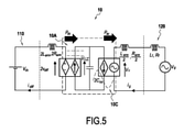
図6に示す本発明の実施形態は、制御モジュール12を含むモジュラマルチレベルコンバータ10に関する。図5は、本発明のコンバータ10の挙動を表す等価回路を単相モデルで示す。図5では、制御モジュールを示していない。単相モデルを使用することは、表記及び図を単純化するのに役立つ。この図では、非限定的に、DCエネルギーをACエネルギーに変換するMMC10を見ることができる。
The embodiment of the present invention shown in FIG. 6 relates to a modular
この例では、コンバータ10は、図の左側部分においてDC電源ネットワーク110に接続されたDC部分10Aを有することが分かる。図の右側部分では、コンバータ10がAC電源ネットワーク120に接続されたAC部分10Cを有することが分かる。図5において、LarmとRarmは、アームにおけるインダクタンス及び抵抗をそれぞれ示し、LfとRfは、位相ラインにおけるインダクタンス及び抵抗をそれぞれ示す。idiffは、DC電源ネットワークを通過する差動電流を示し、vdiffは、コンバータのDC部分の端子間の差動電圧を示す。igは、AC電源ネットワークを通過する電流を示し、Vvは、コンバータのAC部分の端子間の等価AC内部電圧を示す。vgは、AC電源ネットワークの電圧、Vdcは、DC電源ネットワークの電圧を示す。また、DC電源ネットワーク110とコンバータ10との間で交換される電力は、Pdcと書かれており、コンバータ10とAC電源ネットワーク120との間で交換される電力は、Pacと書かれていることが分かる。
In this example, it can be seen that the
図6は、コンバータユニット11及び制御モジュール12を備える本発明のモジュラマルチレベルコンバータ10を示す。制御モジュール12は、制御ループ内にあり、コンバータの上側アーム又は下側アームのサブモジュールSMxijのキャパシタ内に蓄積された内部エネルギーを調整するように構成されている。図6の非限定的な例では、制御モジュール12はまた、コンバータの上アーム又は下アームのキャパシタに蓄えられた内部エネルギーを上限WΣ
Lmaxより小さく、かつ下限WΣ
Lminより大きく制限するのに適している。制御モジュールは、上限WΣ
Lmaxと下限WΣ
Lminとの間に内部エネルギーを保持するように機能し、それによって、コンバータ10を損傷する危険性なしに、コンバータ10の適切な動作を確実にする。
FIG. 6 shows a modular
図6の例から分かるように、制御モジュール12はまた、コンバータの内部エネルギーの下限WΣ
Lmin及び上限WΣ
Lmaxを決定する決定モジュール14を含む。この決定モジュール14は、入力として、AC電源ネットワーク120上で測定される電圧値vg、DC電源ネットワーク110上で測定される電圧値Vdc、有効AC電力設定点P*
ac、無効AC電力設定点Q*
ac、及びDC電力設定点P*
dcを受信する。下限WΣ
Lminと上限WΣ
Lmaxは一定ではなく、電源ネットワークの状態によって異なることがわかる。
As can be seen from the example of FIG. 6, the
好ましくは、非限定的であるが、電圧値vg及びVdcはリアルタイムで測定され、WΣ
LmaxやWΣ
Lminのような値は、リアルタイムでサーボ制御され、常に電源ネットワークの状態に適合される。決定モジュール14の動作については、後に詳述する。
Preferably, but not limited, the voltage values vg and V dc are measured in real time, and values such as W Σ Lmax and W Σ Lmin are servo controlled in real time and are always adapted to the state of the power network. To. The operation of the
図6では、制御モジュール12が補正モジュール16を含むことも分かる。この非限定的な例では、補正モジュール16は、入力として、コンバータ10のアームのキャパシタに蓄積されたエネルギーの内部エネルギー設定点WΣ*を、決定モジュール14によって供給される内部エネルギーの下限WΣ
Lmin及び上限WΣ
Lmaxと共に使用する。補正モジュール16は、補正された内部エネルギー設定点WΣ*´を出力として送出する。
In FIG. 6, it can also be seen that the
補正モジュール16への内部エネルギー設定点WΣ*入力が下限WΣ
Lmin、又は上限WΣ
Lmaxを超えない限り、内部エネルギー設定点WΣ*は変更されない。次いで、補正モジュール16は、入力として受け取る内部エネルギー設定点WΣ*と同一の内部エネルギー設定点WΣ*´を出力として送出する。対照的に、内部エネルギー設定点WΣ*が下限WΣ
Lminより低いか、又は上限WΣ
Lmaxより高い場合、補正モジュール16は、下限より高いか、又は上限より低い補正された内部エネルギー設定点WΣ*´を出力として送出するように、内部エネルギー設定点WΣ*を補正する。
The internal energy setting point W Σ * is not changed unless the internal energy setting point W Σ * input to the
図6の制御モジュール12はまた、コンバータ10の内部エネルギーを調整するためのレギュレータ18を含む。コンバータの内部エネルギーを調整するためのこのレギュレータ18は、補正モジュールによって供給される補正された内部エネルギー設定点WΣ*´から決定されるように、コンバータ10のキャパシタのための電力設定点P*
wを供給する。従って、キャパシタに蓄えられるコンバータの内部エネルギーは、好ましくは同様に好ましくはリアルタイムで補正された内部エネルギー設定点WΣ*´によって、好ましくはリアルタイムで調整される。
The
また、この例では、制御モジュール12は、コンバータとACネットワークとの間の接続点における電力を調整するためのレギュレータ20を含むことが分かる。コンバータとACネットワークとの間の接続点における電力を調整するこのレギュレータ20は、有効AC電力設定点P*
ac及び無効AC電力設定点Q*
acを入力として受信し、AC電流設定点i*
gd及びi*
gqを送出する。
Also, in this example, it can be seen that the
非限定的な方法では、制御モジュール12は、AC電源ネットワーク120のAC電流igを調整するレギュレータ22を含み、レギュレータ22は、入力として、コンバータとACネットワークとの間の接続点における電力を調整するために、レギュレータ20によって供給されるAC電流設定点i*
gd及びi*
gqを受信する。AC電流igを調整するこのレギュレータ22は、MMC10に対して等価AC内部電圧設定点v*
vを出力として供給する。
In a non-limiting manner, the
さらに、図6の例では、決定モジュール14への入力として使用される有効AC電力設定点P*
acも、コンバータ10の内部エネルギーを調整するために、レギュレータ18からの電力設定点P*
wと比較され、加算される。この比較の結果、DC電力設定点P*
dcが、コンバータとDCネットワークとの間の接続点における電力を調整するためのレギュレータ24への入力として供給される。コンバータとDCネットワークとの間の接続点における電力を調整するこのレギュレータ24は、DC電源ネットワークの差動電流idiffを表す差動電流設定点i*
diffを送出する。
Further, in the example of FIG. 6, the effective AC power setting point P * ac used as an input to the
さらに非限定的に、制御モジュール12は、差動電流idiffを調整し、コンバータ10とDC電源ネットワーク110との間の接続点における電力を調整するためにレギュレータ24によって供給される差動電流idiffに関連する差動電流設定点i*
diffを入力として受信するためのレギュレータ26を含む。差動電流idiffを調整するためのレギュレータ26は、出力としてMMC10に差動電圧設定点v*
diffを供給する。
Further, but not limitedly, the
図7は、コンバータ10の内部エネルギーの下限WΣ
Lmin及び上限WΣ
Lmaxを決定するための決定モジュール14の動作を示す。非限定的な方法では、決定モジュール14は、AC電源ネットワーク上で測定された電圧の値vg、DC電源ネットワーク上で測定された電圧の値Vdc、有効AC電力設定点P*
ac、無効AC電力設定点Q*
ac、及びDC電力設定点P*
dcによって構成される入力変数から、ならびにコンバータ10にとって既知であり、特定の状態パラメータのセットから、中間変数を計算するための計算ユニット28を含む。
FIG. 7 shows the operation of the
この例では、状態パラメータは、アームのインダクタンスLarm、位相線のインダクタンスLf及び抵抗Rf、アームのキャパシタのキャパシタンスC、好ましくは同一のキャパシタンスのキャパシタ、サブモジュールに許容可能な最大電圧VsmMax、アームのサブモジュールの数N、及び各サブモジュールのスイッチ素子T1及びT2を構成する絶縁ゲートバイポーラトランジスタの抵抗RIGBTを含む。 In this example, the state parameters are the arm inductance L arm , the phase line inductance L f and resistance R f , the arm capacitor capacitance C, preferably the same capacitance capacitor, the maximum voltage V smMax acceptable for the submodule. , The number N of submodules of the arm, and the resistance R IGBT of the insulated gate bipolar transistor constituting the switch elements T1 and T2 of each submodule.
非限定的に、中間変数は、定常条件下でコンバータの単相モデルにおいてDC電源ネットワークを通って流れる電流を表す等価差動電流変数Idiffと、定常条件下でコンバータのDC部分の端子における定常条件下でのモデルにおける電圧を表す等価差動電圧変数Vdiffと、定常条件下でのコンバータの単相モデルにおける等価AC内部電圧変数Vvと、同様に定常条件下でのコンバータの単相モデルにおけるAC電源ネットワークに流れる電流を表す等価中間電流変数Igとを含む。 Not limited, the intermediate variables are the equivalent differential current variable Idiff , which represents the current flowing through the DC power network in the converter's single-phase model under steady conditions, and the steady at the terminals of the DC portion of the converter under steady conditions. The equivalent differential voltage variable V diff , which represents the voltage in the model under conditions, the equivalent AC internal voltage variable V v in the single-phase model of the converter under steady conditions, and the single-phase model of the converter under steady conditions as well. Includes an equivalent intermediate current variable Ig that represents the current flowing through the AC power network in.
中間変数はまた、角周波数ω、AC電源ネットワークの電圧ベクトルとAC電源ネットワークに流れる電流のベクトルとの間の位相差に対する位相変数θを含む。中間変数は、AC電源ネットワークの電圧ベクトルと等価AC内部電圧ベクトルVvとの間の位相差を表す中間角度変数δも含む。 The intermediate variable also includes the angular frequency ω, the phase variable θ for the phase difference between the voltage vector of the AC power network and the vector of the current flowing through the AC power network. The intermediate variable also includes an intermediate angle variable δ that represents the phase difference between the voltage vector of the AC power network and the equivalent AC internal voltage vector V v .
これらの中間変数に基づいて、決定モジュール14は、構成がコンバータ10にとっては最も好ましくない、アーム内の内部エネルギーが内部エネルギーの下限WΣ
Lminに達する瞬間tmを決定するのに適している。この瞬間tmに、アームに挿入される電圧vmは、そのアーム内のサブモジュールの電圧の合計vcΣに等しい。また、決定モジュール14は、構成がコンバータにとって最も好ましくなく、アーム内の内部エネルギーが内部エネルギーの上限WΣ
Lmaxに達する瞬間trを決定するのに適している。
Based on these intermediate variables, the
決定モジュール14は、コンバータの上側アームのサブモジュールのキャパシタに蓄積された内部エネルギーの振動成分WΣ
ru(t)を決定するのにも適している。本発明の範囲を逸脱することなく、決定モジュール14は、コンバータの下側アームのサブモジュールのキャパシタに蓄積された内部エネルギーの振動成分WΣ
rl(t)を決定するのにも適している。内部エネルギーの振動成分WΣ
ru(t)、瞬間trとtm、及び決定された中間変数から出発して、決定モジュール14は、内部エネルギーの下限WΣ
Lmin及び上限WΣ
Lmaxを決定するのに適している。
The
図8~図13Bは、コンバータのアームのキャパシタに蓄積された内部エネルギーを制御する2つのシミュレーションを示す。これらの図では、より明確にするために、サブモジュールのキャパシタの両端の電圧は別として、電力、エネルギー、及び電圧の大きさは、単位当たりのシステム[p.u.]を使用して与えられ、時間は秒で表される。 8 to 13B show two simulations controlling the internal energy stored in the capacitor of the converter arm. In these figures, for the sake of clarity, apart from the voltage across the capacitors in the submodule, the power, energy, and magnitude of the voltage are the system per unit [p. u. ] Given using, the time is expressed in seconds.
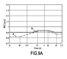
特に、図8~図10Bは、内部エネルギーレベルが下限WΣ Lmin近傍にあるときの2つの系の挙動を明らかにする第1のシミュレーションを示す。図11~図13Bは、内部エネルギーレベルが上限WΣ Lmax付近にある場合の2つの系の挙動を明らかにする第2のシミュレーションを示す。 In particular, FIGS. 8-10B show a first simulation that reveals the behavior of the two systems when the internal energy level is near the lower limit W Σ Lmin . 11 to 13B show a second simulation that reveals the behavior of the two systems when the internal energy level is near the upper limit W Σ Lmax .
第1のシミュレーションでは、図8~図10Bに示すように、2つのシステムの挙動を比較する。図9A及び9Bの曲線によって示される挙動の第1のシステムは、内部エネルギー制御モジュールを含む、本発明のモジュラマルチレベルコンバータからなる。図10A及び図10Bの曲線によって示される挙動の第2のシステムは、内部エネルギー制御モジュールのない先行技術のモジュラマルチレベルコンバータからなる。従って、第2のシステムの内部エネルギーは調整されない。 In the first simulation, the behaviors of the two systems are compared, as shown in FIGS. 8-10B. The first system of behavior shown by the curves of FIGS. 9A and 9B comprises the modular multi-level converter of the present invention, including an internal energy control module. The second system of behavior shown by the curves in FIGS. 10A and 10B consists of a prior art modular multi-level converter without an internal energy control module. Therefore, the internal energy of the second system is not adjusted.
図8は、DC電源ネットワークの電圧Vdcにおける時間の関数としての変化を示し、これはシミュレーションの必要性に対して課される。電圧Vdcは、最初に、瞬間t0から瞬間t1への増加を受け、次いで、電圧Vdcは、瞬間t2から瞬間t3へ減少する。 FIG. 8 shows the change as a function of time in the voltage V dc of the DC power network, which is imposed on the need for simulation. The voltage V dc first undergoes an increase from moment t 0 to moment t 1 , and then the voltage V dc decreases from moment t 2 to moment t 3 .
図9Aは、図8の電圧変化に応答した第1のシステムについて、本発明のコンバータ10のアームのキャパシタに蓄積された内部エネルギーの平均の変化を示し、この図において、曲線aは、時間の関数としての内部エネルギーの下限WΣ
Lminの変化を表す。上記から分かるように、この限界は、制御モジュール12によって、より詳細には決定モジュール14によって決定される。この下限WΣ
Lminは、DC電源ネットワークの電圧Vdcの変動に追従することが分かる。Vdcは、下限WΣ
Lminに著しい影響を与えるパラメータであり、このパラメータを変化させることによって、コンバータ10のアームのキャパシタに蓄積された内部エネルギーの変化を追跡することが容易である。従って、下限WΣ
Lminは、瞬間t0から瞬間t1に増加し、次いで瞬間t2から瞬間t3に減少する。
FIG. 9A shows the change in the average internal energy stored in the capacitor of the arm of the
図9Aの例では、曲線bによって表されるコンバータの内部エネルギーの平均は、初期基準値に維持される。この内部エネルギーレベルが下限WΣ Lminに近づくと、制御モジュールは、このレベルを下限より上に保つように内部エネルギーを調節する。 In the example of FIG. 9A, the average internal energy of the converter represented by the curve b is maintained at the initial reference value. When this internal energy level approaches the lower limit W Σ Lmin , the control module adjusts the internal energy to keep this level above the lower limit.
図9Bは、図8に示したDC電源回路ネットワークの電圧Vdcの変化に対する、この第1のシステムにおける変調指数mの変化を示したものであり、アームに挿入される電圧はDC電源回路ネットワークの電圧Vdcに比例することが知られている。従って、電圧Vdcの増加は、挿入される電圧vmの増加を意味し、それによって変調指数mの増加をもたらす。図9Bの例では、コンバータの内部エネルギーが制御モジュールによって調整されている状態で、変調指数mは、以下の不等式に当てはまるように、1未満に維持される。
![]()
![]()
従って、コンバータの適切な動作が保証される。 Therefore, proper operation of the converter is guaranteed.
図10Aにおいて、図8の電圧変化に応答して、先行技術のコンバータのアームのキャパシタに蓄積された内部エネルギーの平均の、第2のシステムに対する変化が見られる。 In FIG. 10A, in response to the voltage change of FIG. 8, a change in the average internal energy stored in the capacitor of the arm of the prior art converter with respect to the second system is seen.
曲線aは、第1のシステムの制御モジュールによって決定された、内部エネルギーの下限WΣ Lminの変化を示す。曲線b´によってプロットされるように、コンバータの内部エネルギーの平均は、この内部エネルギーのレベルが一定のままであり、瞬間tvに下限WΣ Lminを下回るように調整されないことが分かる。 The curve a shows the change in the lower limit W Σ Lmin of the internal energy determined by the control module of the first system. As plotted by the curve b', it can be seen that the average of the internal energies of the converter remains constant at this level of internal energy and is not adjusted to below the lower bound W Σ Lmin at the moment tv .
図10Bは、第2のシステムの変調指数mの変化を示す。先行技術のコンバータは制御モジュールを有さず、コンバータの内部エネルギーは調整されないので、変調指数mは調整されず、1を超え、瞬間tvから次の不等式がもはや当てはまらない。
![]()
![]()
コンバータの適切な動作はもはや保証されず、コンバータが損傷する危険性がある。 Proper operation of the converter is no longer guaranteed and there is a risk of damage to the converter.
従って、ネットワークの状態に適合された下限WΣ
Lminを決定することに加えて、図9A及び9Bの非限定的なシミュレーション例で使用されるような本発明のコンバータ10の制御モジュール12は、内部エネルギーを下限WΣ
Lminを超えて維持するように働くことが理解され得る。これは、変調指数を1未満に保ち、コンバータが適切に動作することを保証する。
Therefore, in addition to determining the lower bound W Σ Lmin adapted to the state of the network, the
内部エネルギーレベルが上限WΣ Lmaxに近い場合の、コンバータの挙動の第2のシミュレーションの結果を、図11~図13Bを参照して説明する。この第2のシミュレーションでは、2つのシステムの挙動を同様に比較する。再び、図12A及び12Bにおける曲線によって示される挙動の第1のシステムは、内部エネルギー制御モジュールを含む本発明のモジュラマルチレベルコンバータからなる。図13A及び13Bの曲線によって示される挙動の第2のシステムは、内部エネルギー制御モジュールのない先行技術のモジュラマルチレベルコンバータからなる。従って、第2のシステムの内部エネルギーは調整されない。 The results of the second simulation of the behavior of the converter when the internal energy level is close to the upper limit W Σ Lmax will be described with reference to FIGS. 11 to 13B. In this second simulation, the behavior of the two systems is compared in the same way. Again, the first system of behavior shown by the curves in FIGS. 12A and 12B consists of the modular multi-level converter of the invention, including an internal energy control module. The second system of behavior shown by the curves in FIGS. 13A and 13B consists of a prior art modular multi-level converter without an internal energy control module. Therefore, the internal energy of the second system is not adjusted.
図11の曲線cは、一定に保たれる無効AC電力Qacを示し、曲線dは、時間の関数としての有効AC電力Pacを示す。これらの電力は、コンバータとAC電源ネットワークとの間で伝達される電力である。シミュレーションの目的のために、有効AC電力Pacは、最初に瞬間t4から瞬間t5への増加を受け、次いで、電力Pacは、瞬間t6から瞬間t7へ減少する。 The curve c in FIG. 11 shows the invalid AC power Q ac that is kept constant, and the curve d shows the effective AC power P ac as a function of time. These powers are the powers transmitted between the converter and the AC power network. For simulation purposes, the active AC power P ac first undergoes an increase from moment t 4 to moment t 5 , and then the power P ac decreases from moment t 6 to moment t 7 .
図12Aは、図11の電力変化に応答した第1のシステムについて、本発明のコンバータのアームのキャパシタに蓄積された内部エネルギーの平均値の変化を示し、この図において、曲線eは、内部エネルギーの上限WΣ
Lmaxの変化を表す。上述したように、この限界は、制御モジュールによってリアルタイムで決定される。この上限WΣ
Lmaxは、有効AC電力Pacと反対に変化することが分かる。Pacは、上限WΣ
Lmaxに著しい影響を与えるパラメータであり、このパラメータを変化させることによって、コンバータ10のアームのキャパシタに蓄積された内部エネルギーの変化を追跡することが容易である。従って、上限WΣ
Lmaxは、瞬間t4から瞬間t5に減少し、次いで瞬間t6から瞬間t7に増加する。
FIG. 12A shows the change in the mean value of the internal energy stored in the capacitor of the arm of the converter of the present invention for the first system in response to the power change of FIG. 11, in which the curve e is the internal energy. Represents the change in the upper limit W Σ L max of. As mentioned above, this limit is determined in real time by the control module. It can be seen that this upper limit W Σ Lmax changes in the opposite direction to the effective AC power P ac . P ac is a parameter that significantly affects the upper limit W Σ Lmax , and by changing this parameter, it is easy to track the change in the internal energy stored in the capacitor of the arm of the
図12Aの例では、曲線fによって表される、第1のシステムのコンバータの内部エネルギーの平均は、初期基準値に維持される。内部エネルギーのレベルが上限WΣ Lmaxに近づくと、制御モジュールは、内部エネルギーのレベルを上限未満に維持するように内部エネルギーを調整する。 In the example of FIG. 12A, the average of the internal energies of the converter of the first system, represented by the curve f, is maintained at the initial reference value. When the level of internal energy approaches the upper limit W Σ Lmax , the control module adjusts the internal energy to keep the level of internal energy below the upper limit.
図12Bの曲線gは、図11の電力変化に応答した、時間の関数としての第1のシステムのサブモジュールのキャパシタ電圧vcの変化を示す。有効電力Pacの増加、従ってコンバータとAC電源ネットワークとの間の電力交換の増加は、瞬間t4にキャパシタ電圧vcの振動の振幅の増加をもたらす。 The curve g in FIG. 12B shows the change in the capacitor voltage v c of the submodule of the first system as a function of time in response to the power change in FIG. An increase in the active power P ac , and thus an increase in the power exchange between the converter and the AC power network, results in an increase in the amplitude of the vibration of the capacitor voltage v c at the moment t 4 .
サブモジュールの損傷を回避し、コンバータの適切な動作を保証するために、キャパシタ電圧vcは、サブモジュールのスイッチ素子の電圧限界に対応する最大電圧vcMax未満でなければならないことを思い起こすべきである。図12Bの例では、第1のシステムのコンバータの内部エネルギーが制御モジュールによって調整されるので、キャパシタ電圧Vcは、曲線gによって表されるような電圧vcが、曲線hによって表されるようなスイッチ素子の電圧限界vcMaxよりも常に低いままであるように、調整され、ピーク制限される。 It should be remembered that the capacitor voltage v c must be less than the maximum voltage v c Max corresponding to the voltage limit of the switch element of the submodule in order to avoid damage to the submodule and ensure proper operation of the converter. be. In the example of FIG. 12B, since the internal energy of the converter of the first system is adjusted by the control module, the capacitor voltage V c is such that the voltage v c as represented by the curve g is represented by the curve h. It is adjusted and peak limited so that it always remains below the voltage limit v cMax of the switch element.
従って、コンバータの適切な動作が保証され、サブモジュールが損傷する危険はない。 Therefore, proper operation of the converter is guaranteed and there is no risk of damaging the submodule.
図13Aは、図11の電力変化に応答して、制御モジュールを含まない第2のシステムのコンバータのアームのキャパシタに蓄えられた内部エネルギーの変化を示す。曲線eは、第1のシステムの制御モジュールによって決定された、内部エネルギーの上限WΣ Lmaxの変化を示す。 FIG. 13A shows the change in internal energy stored in the capacitor of the arm of the converter of the second system, which does not include the control module, in response to the change in power of FIG. The curve e shows the change in the upper limit W Σ Lmax of the internal energy determined by the control module of the first system.
この図13Aにおいて、曲線fによって表されるコンバータの内部エネルギーのレベルは、内部エネルギーのこのレベルが一定のままであり、瞬間tuに上限WΣ Lmaxを超えて通過するように調整されないことが分かる。 In FIG. 13A, the level of internal energy of the converter represented by the curve f is that this level of internal energy remains constant and is not adjusted to pass above the upper bound W Σ Lmax at the moment tu. I understand.
図13Bの曲線g´は、図11の電力変化に応答した、時間の関数としての第2のシステムのサブモジュールのキャパシタの電圧vcの変化を示す。この例では、第2のシステムのコンバータは内部エネルギー制御モジュールを有していないので、第2のシステムのコンバータの内部エネルギーは調整されない。また、キャパシタ電圧vcは、瞬間tuから曲線hによって表されるように、電圧vcがスイッチ素子の電圧限界vcMaxよりも大きくなるように調整されない。 The curve g'in FIG. 13B shows the change in voltage v c of the capacitor of the submodule of the second system as a function of time in response to the power change in FIG. In this example, the converter of the second system does not have an internal energy control module, so the internal energy of the converter of the second system is not tuned. Also, the capacitor voltage v c is not adjusted so that the voltage v c is greater than the voltage limit v c Max of the switch element, as represented by the curve h from the moment t u .
サブモジュールは損傷を受ける危険があり、従ってコンバータの適切な動作はもはや保証されない。 Submodules are at risk of damage and therefore proper operation of the converter is no longer guaranteed.
従って、ネットワークの状態に適合される内部エネルギーの上限WΣ
Lmaxを決定することに加えて、図12A及び12Bの非限定的なシミュレーション例で使用されるような、本発明のコンバータ10の制御モジュール12は、内部エネルギーを上限WΣ
Lmax未満に維持する働きをすることが理解され得る。これにより、電圧vcはスイッチ素子の電圧限界vcMax以下に保たれる。
Therefore, in addition to determining the upper limit of internal energy W Σ Lmax adapted to the state of the network, the control module of the
Claims (21)
前記コンバータは、DC電源ネットワーク(110)へ接続するためのDC部分(10A)と、AC電源ネットワーク(120)へ接続するためのAC部分(10C)とを備え、
前記コンバータは、複数の脚を備え、
それぞれの前記脚は、上側アーム及び下側アームを備え、
それぞれのアームは、各サブモジュールに特有の制御部材によって個々に制御可能な複数のサブモジュール(SMxij)を備え、
それぞれのサブモジュールは、各サブモジュールの制御部材が「オン」状態にあるときに前記アーム内に直列に接続可能なキャパシタ(CSM)を備え、
前記コンバータは、前記コンバータの上側又は下側アームのサブモジュールのキャパシタ内に蓄積された内部エネルギーを調整するように構成された制御モジュール(12)を含み、
前記制御モジュールは、コンバータの動作電力の設定値と共にモジュールDC電源ネットワーク及びAC電源ネットワークで測定されるパラメータを使用することによって、前記内部エネルギーを上限より小さく及び/又は下限より大きくなるように制限するのに適しており、
前記制御モジュールは、前記DC電源ネットワーク及び前記AC電源ネットワーク上で測定されたパラメータを使用して、前記内部エネルギーの上限及び/又は下限を決定するように構成されており、前記内部エネルギーの上限及び/又は下限は、前記DC電源ネットワーク及び前記AC電源ネットワークの状態に応じて変化することを特徴とするモジュラマルチレベル電圧コンバータ。 A modular multi-level voltage converter (10) that converts AC voltage to DC voltage or vice versa.
The converter includes a DC portion (10A) for connecting to a DC power supply network (110) and an AC portion (10C) for connecting to an AC power supply network (120).
The converter has multiple legs and
Each said leg comprises an upper arm and a lower arm.
Each arm has multiple submodules (SM xij ) that can be individually controlled by control components specific to each submodule.
Each submodule comprises a capacitor ( CSM ) that can be connected in series within said arm when the control member of each submodule is in the "on" state.
The converter comprises a control module (12) configured to regulate the internal energy stored in the capacitors of the submodules of the upper or lower arm of the converter.
The control module limits the internal energy to less than the upper limit and / or greater than the lower limit by using parameters measured in the module DC power network and AC power network along with the converter operating power setting. Suitable for
The control module is configured to determine an upper and / or lower limit of the internal energy using parameters measured on the DC power network and the AC power network, the upper limit of the internal energy and the upper limit of the internal energy. / Or a modular multi-level voltage converter characterized in that the lower limit varies depending on the state of the DC power supply network and the AC power supply network.


前記制御モジュールは、前記AC電源ネットワーク上で測定される前記電圧値vg、前記DC電源ネットワーク上で測定される前記電圧値Vdc、前記有効AC電力設定点P* ac、前記無効AC電力設定点Q* ac及び前記DC電力設定点P* dcの関数として、上側アーム又は下側アームのサブモジュールの前記キャパシタに蓄積される内部エネルギーの前記下限及び前記上限を決定するための決定モジュール(14)を含む、請求項2に記載のコンバータ。 The operating power setting point of the converter includes an effective AC power setting point P * ac, an invalid AC power setting point Q * ac, and a DC power setting point P * dc.
The control module has the voltage value v g measured on the AC power supply network, the voltage value V dc measured on the DC power supply network, the effective AC power setting point P * ac , and the invalid AC power setting. A determination module (14) for determining the lower limit and the upper limit of the internal energy stored in the capacitor of the submodule of the upper arm or the lower arm as a function of the point Q * ac and the DC power setting point P * dc . The converter according to claim 2.
前記コンバータは、DC電源ネットワークへ接続するためのDC部分と、AC電源ネットワークへ接続するためのAC部分とを備え、
前記コンバータは、複数の脚を備え、
それぞれの前記脚は、上側アーム及び下側アームを備え、
それぞれのアームは、各サブモジュールに特有の制御部材によって個々に制御可能な複数のサブモジュールを備え、
それぞれのサブモジュールは、各サブモジュールの制御部材が「オン」状態にあるときに、前記アーム内に直列に接続可能なキャパシタを備え、
前記コンバータは、前記コンバータの上側又は下側アームのサブモジュールのキャパシタに蓄積された内部エネルギーを調整するステップを含み、
前記内部エネルギーは、DC電源ネットワーク及びAC電源ネットワーク上で測定されたパラメータを、コンバータの動作電力の設定値と共に使用することによって、上限より小さく及び/又は下限より大きくなるように制限され、
前記内部エネルギーの上限及び/又は下限が、前記DC電源ネットワーク及び前記AC電源ネットワーク上で測定されたパラメータを使用して決定され、前記DC電源ネットワーク及び前記AC電源ネットワークの状態に応じて変化することを特徴とするモジュラマルチレベル電圧コンバータの制御方法。
A control method for a modular multi-level voltage converter (10) that converts an AC voltage to a DC voltage or vice versa.
The converter includes a DC portion for connecting to a DC power supply network and an AC portion for connecting to an AC power supply network.
The converter has multiple legs and
Each said leg comprises an upper arm and a lower arm.
Each arm has multiple submodules that can be individually controlled by control members specific to each submodule.
Each submodule comprises a capacitor that can be connected in series in the arm when the control member of each submodule is in the "on" state.
The converter comprises adjusting the internal energy stored in the capacitor of the submodule of the upper or lower arm of the converter.
The internal energy is limited to less than the upper limit and / or greater than the lower limit by using the parameters measured on the DC and AC power networks together with the converter operating power settings .
The upper and / or lower limits of the internal energy are determined using the parameters measured on the DC power network and the AC power network and vary depending on the state of the DC power network and the AC power network. A method of controlling a modular multi-level voltage converter that features.
Applications Claiming Priority (3)
| Application Number | Priority Date | Filing Date | Title |
|---|---|---|---|
| FR1656432A FR3053854B1 (en) | 2016-07-05 | 2016-07-05 | MODULE FOR CONTROLLING THE INTERNAL ENERGY OF A CONVERTER |
| FR1656432 | 2016-07-05 | ||
| PCT/FR2017/051803 WO2018007741A1 (en) | 2016-07-05 | 2017-07-03 | Module for controlling the internal energy of a converter |
Publications (3)
| Publication Number | Publication Date |
|---|---|
| JP2019520023A JP2019520023A (en) | 2019-07-11 |
| JP2019520023A5 JP2019520023A5 (en) | 2020-07-27 |
| JP7008043B2 true JP7008043B2 (en) | 2022-01-25 |
Family
ID=57396553
Family Applications (1)
| Application Number | Title | Priority Date | Filing Date |
|---|---|---|---|
| JP2018566832A Active JP7008043B2 (en) | 2016-07-05 | 2017-07-03 | Module for internal energy control of converter |
Country Status (10)
| Country | Link |
|---|---|
| US (1) | US10615714B2 (en) |
| EP (1) | EP3482487B1 (en) |
| JP (1) | JP7008043B2 (en) |
| KR (1) | KR102417718B1 (en) |
| CN (1) | CN109565246B (en) |
| CA (1) | CA3029698A1 (en) |
| FR (1) | FR3053854B1 (en) |
| PL (1) | PL3482487T3 (en) |
| RU (1) | RU2730279C2 (en) |
| WO (1) | WO2018007741A1 (en) |
Families Citing this family (2)
| Publication number | Priority date | Publication date | Assignee | Title |
|---|---|---|---|---|
| EP3614552B1 (en) * | 2018-08-24 | 2021-05-19 | General Electric Technology GmbH | Voltage source converter |
| EP3654517B1 (en) * | 2018-11-19 | 2021-06-02 | Maschinenfabrik Reinhausen GmbH | Operating a modular multilevel converter |
Citations (2)
| Publication number | Priority date | Publication date | Assignee | Title |
|---|---|---|---|---|
| JP2014233168A (en) | 2013-05-30 | 2014-12-11 | 富士電機株式会社 | Modular multilevel converter |
| WO2015178376A1 (en) | 2014-05-21 | 2015-11-26 | 三菱電機株式会社 | Direct-current power transmission power conversion device and direct-current power transmission power conversion method |
Family Cites Families (13)
| Publication number | Priority date | Publication date | Assignee | Title |
|---|---|---|---|---|
| JP3967706B2 (en) * | 2003-10-22 | 2007-08-29 | 三菱電機株式会社 | Power converter |
| CN101911463B (en) * | 2008-01-08 | 2013-09-04 | Abb技术有限公司 | A method for controlling a voltage source converter and a voltage converting apparatus |
| CN102215004B (en) * | 2011-03-16 | 2014-07-30 | 中国电力科学研究院 | Valve current control method based on modular multi-level converter |
| CN102130619B (en) * | 2011-03-21 | 2014-07-02 | 中国电力科学研究院 | Voltage balancing control method for multi-level modular converter |
| CN103503298B (en) * | 2011-04-01 | 2016-08-17 | 西门子公司 | For producing method and the apparatus for carrying out the method for output voltage |
| JP5894777B2 (en) * | 2011-12-07 | 2016-03-30 | 株式会社日立製作所 | Power converter |
| US9252681B2 (en) * | 2013-08-30 | 2016-02-02 | General Electric Company | Power converter with a first string having controllable semiconductor switches and a second string having switching modules |
| DE102013219466A1 (en) * | 2013-09-26 | 2015-03-26 | Siemens Aktiengesellschaft | Multilevelumrichter |
| CN103904658A (en) * | 2014-03-31 | 2014-07-02 | 南方电网科学研究院有限责任公司 | Modular multilevel converter with bridge arm redundancy function and its control method |
| EP2978122A1 (en) * | 2014-07-22 | 2016-01-27 | ABB Technology AG | Model predictive control of a modular multilevel converter |
| CN104917393B (en) * | 2015-06-09 | 2018-02-16 | 合肥科威尔电源系统有限公司 | A kind of photovoltaic energy storage integrated DC converter structure based on MMC technologies |
| CN105245087B (en) * | 2015-10-26 | 2017-11-14 | 南方电网科学研究院有限责任公司 | Classification-Based Capacitor Voltage Equalization Control Method for Modular Multilevel Converter |
| CN105577011B (en) * | 2016-01-18 | 2018-02-02 | 电子科技大学 | A kind of DC capacitor capacity acquiring method of three-level inverter |
-
2016
- 2016-07-05 FR FR1656432A patent/FR3053854B1/en not_active Expired - Fee Related
-
2017
- 2017-07-03 PL PL17745819T patent/PL3482487T3/en unknown
- 2017-07-03 WO PCT/FR2017/051803 patent/WO2018007741A1/en not_active Ceased
- 2017-07-03 CA CA3029698A patent/CA3029698A1/en not_active Abandoned
- 2017-07-03 EP EP17745819.7A patent/EP3482487B1/en active Active
- 2017-07-03 US US16/313,951 patent/US10615714B2/en active Active
- 2017-07-03 RU RU2019102914A patent/RU2730279C2/en active
- 2017-07-03 KR KR1020197003490A patent/KR102417718B1/en not_active Expired - Fee Related
- 2017-07-03 CN CN201780042175.0A patent/CN109565246B/en not_active Expired - Fee Related
- 2017-07-03 JP JP2018566832A patent/JP7008043B2/en active Active
Patent Citations (2)
| Publication number | Priority date | Publication date | Assignee | Title |
|---|---|---|---|---|
| JP2014233168A (en) | 2013-05-30 | 2014-12-11 | 富士電機株式会社 | Modular multilevel converter |
| WO2015178376A1 (en) | 2014-05-21 | 2015-11-26 | 三菱電機株式会社 | Direct-current power transmission power conversion device and direct-current power transmission power conversion method |
Non-Patent Citations (1)
| Title |
|---|
| Jie Guo et al.,"Energy storable VSC-HVDC system based on moduler multilevel converter",International Journal of Electrical Power and Energy Systems,英国,vol. 78,pp. 269-276. |
Also Published As
| Publication number | Publication date |
|---|---|
| US20190190399A1 (en) | 2019-06-20 |
| RU2019102914A3 (en) | 2020-08-05 |
| CN109565246B (en) | 2021-11-12 |
| EP3482487A1 (en) | 2019-05-15 |
| RU2019102914A (en) | 2020-08-05 |
| CA3029698A1 (en) | 2018-01-11 |
| EP3482487B1 (en) | 2022-03-23 |
| PL3482487T3 (en) | 2022-06-27 |
| BR112018077243A2 (en) | 2019-04-02 |
| RU2730279C2 (en) | 2020-08-21 |
| KR102417718B1 (en) | 2022-07-06 |
| CN109565246A (en) | 2019-04-02 |
| FR3053854A1 (en) | 2018-01-12 |
| FR3053854B1 (en) | 2018-08-17 |
| WO2018007741A1 (en) | 2018-01-11 |
| JP2019520023A (en) | 2019-07-11 |
| US10615714B2 (en) | 2020-04-07 |
| KR20190028724A (en) | 2019-03-19 |
Similar Documents
| Publication | Publication Date | Title |
|---|---|---|
| CN107925362B (en) | Virtual capacitor | |
| US9640997B2 (en) | Power system stabilization using distributed inverters | |
| CN105900307B (en) | Control of DC Transmission Lines | |
| EP2474087A1 (en) | A method and apparatus for calculating insertion indeces for a modular multilevel converter | |
| Penthia et al. | Performance of SMES system with non‐linear dynamic evolution control approach for pulsed power load compensation | |
| JP7008043B2 (en) | Module for internal energy control of converter | |
| JP7168645B2 (en) | Converter with a module for managing power in the AC part | |
| CN105981287A (en) | Improvements in or relating to converter control | |
| CN113241753B (en) | An Improved Virtual Generator Control Method for DC Microgrid | |
| Issa et al. | Impedance interaction between islanded parallel voltage source inverters and the distribution network | |
| Fan et al. | IDA‐PB control design for VSC‐HVDC transmission based on PCHD model | |
| CN112039106A (en) | Suppression method of DC voltage fluctuation based on MMC virtual capacitor | |
| EP4360204A1 (en) | State feed-back controller for controlling a power converter | |
| Ganesh et al. | A novel robust STATCOM control scheme for stability enhancement in multimachine power system | |
| CN107171331B (en) | Voltage dynamic compensation method based on inverter equivalent impedance | |
| Gawande et al. | State feedback‐based capacitor voltage equalisation scheme in distribution static compensator for load compensation | |
| CN109906555A (en) | The active electronic of one passive circuit component emulates | |
| Esparza et al. | Optimal design of power electronics converters using the extended harmonic domain | |
| Ramirez et al. | An improved SVPWM control of voltage imbalance in capacitors of a single-phase multilevel inverter | |
| BR112018077243B1 (en) | MODULAR MULTI-LEVEL VOLTAGE CONVERTER AND METHOD FOR CONTROLLING A MODULAR MULTI-LEVEL VOLTAGE CONVERTER | |
| Xiao et al. | Mitigation of Active Power Oscillation in Multi-VSG Grids: An Impedance-Based Perspective | |
| CN107667466A (en) | The improvement of the control of voltage source converter or the improvement related to the control of voltage source converter | |
| Jain et al. | Modeling and Control of STATCOMs |
Legal Events
| Date | Code | Title | Description |
|---|---|---|---|
| A521 | Request for written amendment filed |
Free format text: JAPANESE INTERMEDIATE CODE: A821 Effective date: 20190311 |
|
| RD01 | Notification of change of attorney |
Free format text: JAPANESE INTERMEDIATE CODE: A7426 Effective date: 20190311 |
|
| A521 | Request for written amendment filed |
Free format text: JAPANESE INTERMEDIATE CODE: A523 Effective date: 20200610 |
|
| A621 | Written request for application examination |
Free format text: JAPANESE INTERMEDIATE CODE: A621 Effective date: 20200610 |
|
| A977 | Report on retrieval |
Free format text: JAPANESE INTERMEDIATE CODE: A971007 Effective date: 20210426 |
|
| A131 | Notification of reasons for refusal |
Free format text: JAPANESE INTERMEDIATE CODE: A131 Effective date: 20210527 |
|
| A521 | Request for written amendment filed |
Free format text: JAPANESE INTERMEDIATE CODE: A523 Effective date: 20210812 |
|
| A131 | Notification of reasons for refusal |
Free format text: JAPANESE INTERMEDIATE CODE: A131 Effective date: 20210831 |
|
| A521 | Request for written amendment filed |
Free format text: JAPANESE INTERMEDIATE CODE: A523 Effective date: 20211129 |
|
| TRDD | Decision of grant or rejection written | ||
| A01 | Written decision to grant a patent or to grant a registration (utility model) |
Free format text: JAPANESE INTERMEDIATE CODE: A01 Effective date: 20211214 |
|
| A61 | First payment of annual fees (during grant procedure) |
Free format text: JAPANESE INTERMEDIATE CODE: A61 Effective date: 20220107 |
|
| R150 | Certificate of patent or registration of utility model |
Ref document number: 7008043 Country of ref document: JP Free format text: JAPANESE INTERMEDIATE CODE: R150 |
|
| R250 | Receipt of annual fees |
Free format text: JAPANESE INTERMEDIATE CODE: R250 |