JP7062425B2 - Surface-treated steel sheet and its manufacturing method - Google Patents
Surface-treated steel sheet and its manufacturing method Download PDFInfo
- Publication number
- JP7062425B2 JP7062425B2 JP2017236457A JP2017236457A JP7062425B2 JP 7062425 B2 JP7062425 B2 JP 7062425B2 JP 2017236457 A JP2017236457 A JP 2017236457A JP 2017236457 A JP2017236457 A JP 2017236457A JP 7062425 B2 JP7062425 B2 JP 7062425B2
- Authority
- JP
- Japan
- Prior art keywords
- nickel
- steel sheet
- roughened
- nickel layer
- treated steel
- Prior art date
- Legal status (The legal status is an assumption and is not a legal conclusion. Google has not performed a legal analysis and makes no representation as to the accuracy of the status listed.)
- Active
Links
Images





Landscapes
- Laminated Bodies (AREA)
- Electroplating And Plating Baths Therefor (AREA)
- Electroplating Methods And Accessories (AREA)
- Other Surface Treatments For Metallic Materials (AREA)
Description
本発明は、表面処理鋼板およびその製造方法に関する。 The present invention relates to a surface-treated steel sheet and a method for producing the same.
従来、電池を構成する部材や、電子関連機器を構成する部材として、ニッケルめっき鋼板が用いられている。このようなニッケルめっき鋼板においては、他の部材と接合する場合に、密着性を向上させるという観点で、ニッケルめっき鋼板の表面構造を制御する方法が知られている。 Conventionally, nickel-plated steel sheets have been used as members constituting batteries and members constituting electronic-related devices. In such a nickel-plated steel sheet, a method of controlling the surface structure of the nickel-plated steel sheet is known from the viewpoint of improving the adhesion when joining with other members.
たとえば、特許文献1では、鋼板上に、粒子密度:2~500個/μm2、平均粒径:0.05~0.7μmに制御された微細構造を有するニッケルめっき層を形成してなる表面処理鋼板が開示されている。
For example, in
しかしながら、上記特許文献1に開示されている表面処理鋼板では、表面処理鋼板と接合する部材の種類や、接合方法によっては、他の部材との密着性が不十分である場合があり、密着性のさらなる向上が求められていた。
However, the surface-treated steel sheet disclosed in
本発明の目的は、他の部材との密着性に優れた表面処理鋼板を提供することである。 An object of the present invention is to provide a surface-treated steel sheet having excellent adhesion to other members.
本発明者らは、鋼板の少なくとも一方の面の最表面に、特定の粗化ニッケル層を形成することにより、上記目的を達成することができることを見出し、本発明を完成させるに至った。 The present inventors have found that the above object can be achieved by forming a specific roughened nickel layer on the outermost surface of at least one surface of a steel sheet, and have completed the present invention.
すなわち、本発明によれば、鋼板の少なくとも一方の面に、最表層として粗化ニッケル層を備える表面処理鋼板であって、前記粗化ニッケル層は、最大高さ粗さRzが5μm以上であり、かつ、前記粗化ニッケル層の表面から変位計により測定した場合に、前記変位計の測定範囲内で最も高さが低い位置を高さの基準としたときの、前記最大高さ粗さRz×0.75の高さ位置で測定されるニッケルの占有率SRz0.75が1.0%以上である表面処理鋼板が提供される。 That is, according to the present invention, the surface-treated steel sheet is provided with a roughened nickel layer as the outermost surface layer on at least one surface of the steel sheet, and the roughened nickel layer has a maximum height roughness Rz of 5 μm or more. Moreover, when measured from the surface of the roughened nickel layer by a displacement meter, the maximum height roughness Rz when the position having the lowest height within the measurement range of the displacement meter is used as a reference for the height. Provided is a surface-treated steel sheet having a nickel occupancy S Rz 0.75 measured at a height position of × 0.75 of 1.0% or more.
本発明の表面処理鋼板において、前記粗化ニッケル層は、前記粗化ニッケル層の表面から変位計で測定した場合に、前記変位計の測定範囲内で最も高さが低い位置から、最も高さが高い位置まで、各高さ位置でのニッケルの占有率を測定した際における、測定された占有率から求められる体積(単位は、μm3)が、前記測定範囲の単位面積(単位は、μm2)あたり2.7~25μm3/μm2であることが好ましい。
本発明の表面処理鋼板において、前記粗化ニッケル層は、前記粗化ニッケル層の表面から変位計により測定した場合に、前記変位計の測定範囲内で最も高さが低い位置を高さの基準としたときの、5μmの高さ位置で測定されるニッケルの占有率S5μmが10%以上であることが好ましい。
本発明の表面処理鋼板において前記粗化ニッケル層は、前記最大高さ粗さRz(単位は、μm)に対する、前記粗化ニッケル層中のニッケル量ANi(単位は、g/m2)の比(ANi/Rz)で表される粗化指数CA/Rzが、0.1~4.0であることが好ましい。
In the surface-treated steel plate of the present invention, the roughened nickel layer has the highest height from the lowest position within the measurement range of the displacement meter when measured from the surface of the roughened nickel layer with a displacement meter. The volume (unit: μm 3 ) obtained from the measured occupancy when measuring the occupancy of nickel at each height position up to a high position is the unit area (unit: μm) of the measurement range. 2 ) is preferably 2.7 to 25 μm 3 / μm 2 .
In the surface-treated steel sheet of the present invention, the roughened nickel layer is measured from the surface of the roughened nickel layer by a displacement meter, and the lowest height within the measurement range of the displacement meter is used as a reference for height. It is preferable that the occupancy rate S of nickel measured at a height position of 5 μm is 10% or more.
In the surface-treated steel sheet of the present invention, the roughened nickel layer has a nickel amount A Ni (unit: g / m 2 ) in the roughened nickel layer with respect to the maximum height roughness Rz (unit: μm). The roughness index CA / Rz expressed by the ratio ( A Ni / Rz) is preferably 0.1 to 4.0.
さらに、本発明によれば、上述した表面処理鋼板の製造方法であって、前記鋼板に対して粗化ニッケルめっきを施すことにより、前記鋼板上に、ニッケル粒状物を凝集させた状態で析出させることで、前記粗化ニッケル層を形成する表面処理鋼板の製造方法が提供される。 Further, according to the present invention, in the above-mentioned method for producing a surface-treated steel sheet, the steel sheet is subjected to roughened nickel plating to precipitate nickel granules on the steel sheet in an aggregated state. This provides a method for manufacturing a surface-treated steel sheet that forms the roughened nickel layer.
本発明の表面処理鋼板の製造方法において、前記ニッケル粒状物を凝集させた状態で析出させた後、さらにニッケルめっきを施すことにより前記ニッケル粒状物をニッケル被膜で被覆することで、前記粗化ニッケル層を形成することが好ましい。 In the method for producing a surface-treated steel sheet of the present invention, the nickel granules are precipitated in an aggregated state, and then nickel plating is further applied to coat the nickel granules with a nickel film, whereby the roughened nickel is formed. It is preferable to form a layer.
本発明によれば、鋼板の少なくとも一方の面の最表面に、特定の粗化ニッケル層を形成することにより、他の部材との密着性に優れた表面処理鋼板を提供することができるようになる。 According to the present invention, by forming a specific roughened nickel layer on the outermost surface of at least one surface of a steel sheet, it is possible to provide a surface-treated steel sheet having excellent adhesion to other members. Become.
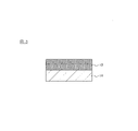
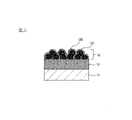
図1は、本実施形態の表面処理鋼板1の構成を示す図である。図1に示すように、本実施形態の表面処理鋼板1は、鋼板11上に、最表層として粗化ニッケル層12が形成されてなる。本実施形態に係る表面処理鋼板1においては、粗化ニッケル層12は、ニッケルめっきによってニッケルが突起状に析出してなる構造を有しており、粗化ニッケル層12中に含まれるニッケル量に対して、粗化ニッケル層12の高さ(厚み)が比較的大きく、嵩高い構造となっている。たとえば、本実施形態の粗化ニッケル層12としては、図2に示すように、破線で示す粗化ニッケル層12の底部から所定の高さ位置にて観察した場合に、多くのニッケルが存在し、その結果、その高さ位置でのニッケルの占有率が高くなるような構造が挙げられる。
FIG. 1 is a diagram showing the configuration of the surface-treated
<鋼板11>
本実施形態の表面処理鋼板1の基板となる鋼板11としては、特に限定されないが、粗化ニッケル層12との密着性に優れるものが好ましく、たとえば、低炭素アルミキルド鋼(炭素量0.01~0.15重量%)、炭素量が0.003重量%以下の極低炭素鋼、または極低炭素鋼にTiやNbなどを添加してなる非時効性極低炭素鋼を用いることができる。
<Steel
The
本実施形態においては、これらの鋼の熱間圧延板を酸洗して表面のスケール(酸化膜)を除去した後、冷間圧延し、次いで圧延油を電解洗浄したもの、あるいは前記電解洗浄後に、焼鈍、調質圧延したものを基板として用いることができる。この場合における、焼鈍は、連続焼鈍あるいは箱型焼鈍のいずれでもよく、特に限定されない。 In the present embodiment, the hot-rolled plates of these steels are pickled to remove surface scale (oxide film), then cold-rolled, and then the rolling oil is electrolytically washed, or after the electrolytic cleaning. , Annealed, tempered and rolled can be used as a substrate. In this case, the annealing may be either continuous annealing or box-type annealing, and is not particularly limited.
<粗化ニッケル層12>
本実施形態の表面処理鋼板の粗化ニッケル層12は、最大高さ粗さRzが5μm以上であり、かつ、粗化ニッケル層12の表面から変位計により測定した場合に、変位計の測定範囲内で最も高さが低い位置を高さの基準としたときの、該最大高さ粗さRz×0.75の高さ位置で測定されるニッケルの占有率SRz0.75が1.0%以上となるように制御されたものである。
<Roughened
The roughened
本実施形態の表面処理鋼板1は、このような粗化ニッケル層12が、鋼板11上に最表層として形成されていることにより、表面処理鋼板1を他の部材と接合する際に、他の部材との密着性に優れたものとすることができるものである。すなわち、粗化ニッケル層12は、最大高さ粗さRzが比較的大きく、かつ、粗化ニッケル層12の表面における所定の高さ位置でのニッケルの占有率が比較的高い構造となっている。これにより、本実施形態の表面処理鋼板1は、最表層を構成する粗化ニッケル層12を、他の部材と良好に接合させることができるようになり、他の部材との密着性に優れたものとなる。
The surface-treated
本実施形態においては、粗化ニッケル層12は、たとえば図3~5に示すような方法で形成することができる。まず、図3に示すように、鋼板11上に、鋼板11と粗化ニッケル層12との密着性をより向上させるという観点より、必要に応じて下地ニッケル層13を形成する。なお、この下地ニッケル層13は形成せずに、鋼板11上に、直接、粗化ニッケル層12を形成するようにしてもよい。次いで、図4に示すように、ニッケルめっきを施すことにより、鋼板11上に、ニッケル粒状物121を凝集させた状態で析出させることで、粗化ニッケル層12を形成する。なお、粗化ニッケル層12は、ニッケル粒状物121のみによって形成されたものであってもよいが、粗化ニッケル層12の剥離をより有効に抑制するという観点より、図5に示すように、ニッケル粒状物121をニッケル被膜122により被覆したものであってもよい。
In the present embodiment, the
これにより、得られる表面処理鋼板1は、図6に示すように、粗化ニッケル層12上に、樹脂等の他の部材14が接合された場合に、粗化ニッケル層12によるアンカー効果によって、表面処理鋼板1と他の部材14との密着性に顕著に優れたものとなる。
As shown in FIG. 6, the surface-treated
粗化ニッケル層12のニッケル量ANiは、60.0g/m2以下であればよいが、45g/m2以下が好ましく、25g/m2以下がより好ましく、更に20g/m2以下がより好ましい。粗化ニッケル層12のニッケル量ANiが多すぎると、粗化ニッケル層12の鋼板11に対する密着性が低下してしまうおそれがある。すなわち、上述した嵩高い構造の粗化ニッケル層12を形成する際には、ニッケル量ANiを多くして粗化ニッケル層12の高さ(厚み)を大きくしすぎてしまうと、粗化ニッケル層が疎になりすぎて密着が保てず脆くなったり、(粗化ニッケル層中の)最表層の方の粗大化に(粗化ニッケル層中の)下層側が耐えきれず粗化ニッケル層が破断したりといったことに起因する構造上の強度の低下が起こり、結果として粗化ニッケル層12が剥離してしまうおそれがある。なお、粗化ニッケル層12のニッケル量ANiの下限は、特に限定されないが、表面処理鋼板1と他の部材との密着性がより向上するという観点より、0.8g/m2以上が好ましく、1.5g/m2以上がより好ましく、3.5g/m2以上がさらに好ましい。なお、粗化ニッケル層12のニッケル量ANiは、下地ニッケル層13が形成されていない場合には、得られた表面処理鋼板1について蛍光X線装置を用いて総ニッケル量を測定することで求めることができ、一方、下地ニッケル層13が形成されている場合には、表面処理鋼板1について蛍光X線装置を用いて総ニッケル量を測定した後、この総ニッケル量から、下地ニッケル層13に相当するニッケル量の分を差し引くことで求めることができる。下地ニッケル層13に相当するニッケル量は、たとえば、得られた表面処理鋼板1を切断し、断面を走査型電子顕微鏡(SEM)により観察することで、下地ニッケル層の厚みを計測し、下地ニッケル層の厚みから換算されるニッケル量を求める方法や、鋼板上に下地ニッケル層13を形成した時点における鋼板上のニッケル量を蛍光X線装置を用いて測定する方法や、鋼板に対してめっきにより下地ニッケル層13を形成する際のクーロン量から算出される電析量から求める方法などが挙げられる。
The nickel amount A Ni of the roughened
また、粗化ニッケル層12の最大高さ粗さRzは、特に限定されないが、5μm以上が好ましく、8μm以上がより好ましく、10μm以上がさらに好ましい。粗化ニッケル層12の最大高さ粗さRzを上記範囲とすることにより、表面処理鋼板1と他の部材との密着性をより向上させることができる。なお、粗化ニッケル層12の最大高さ粗さRzの上限は、特に限定されないが、粗化ニッケル層12の剥離をより有効に抑制することができるという観点より、70μm以下が好ましく、40μm以下がより好ましく、30μm以下がさらに好ましい。
The maximum height roughness Rz of the roughened
さらに、本実施形態の表面処理鋼板1においては、粗化ニッケル層12の算術平均粗さRaが、好ましくは0.75~6.0μm、より好ましくは0.9~3.0μm、さらに好ましくは1.0~2.0μmである。算術平均粗さRaを上記範囲に制御することにより、表面処理鋼板1と他の部材との密着性をより向上させることができるようになる。
Further, in the surface-treated
さらに、本実施形態の表面処理鋼板1においては、粗化ニッケル層12の十点平均粗さRzjisが、5μm以上が好ましく、8μm以上がより好ましく、10μm以上がさらに好ましい。十点平均粗さRzjisを上記範囲に制御することにより、表面処理鋼板1と他の部材との密着性をより向上させることができるようになる。
Further, in the surface-treated
また、本実施形態の表面処理鋼板1においては、粗化ニッケル層12における最大高さ粗さRzと十点平均粗さRzjisとの差分(Rz-Rzjis)が、好ましくは0.05~3.5μm、より好ましくは0.1~3.0μm、特に最大高さ粗さRzが30μm以下の場合、さらに好ましくは0.1~2.0μmである。最大高さ粗さRzと十点平均粗さRzjisとの差分(Rz-Rzjis)が小さいということは、すなわち、より均一に凹凸が形成されているということであり、上記範囲に制御することにより、表面処理鋼板1と他の部材との密着性をより向上させることができるようになる。
Further, in the surface-treated
また、粗化ニッケル層12は、表面から変位計により測定した場合に(さらに具体的には変位計を用いて表面から、鋼板に対し垂直な方向から測定した場合に)、変位計の測定範囲内で最も高さが低い位置を高さの基準としたときの、5μmの高さ位置で測定されるニッケルの占有率(以下、「占有率S5μm」と称する。)が、1%以上であることが好ましく、10%以上であることがより好ましく、20%以上であることがさらに好ましい。占有率S5μmを上記範囲とすることにより、すなわち、凹凸状の粗化ニッケル層12の底部から5μmの高さ位置におけるニッケルの占有率を上記範囲とすることにより(粗化ニッケル層12の表面にてニッケルが突出した部分が適度に存在するように制御することにより)、表面処理鋼板1と他の部材との密着性をより向上させることができる。なお、占有率S5μmの上限は、特に限定されないが、粗化ニッケル層12の剥離をより有効に抑制することができるという観点より、99%以下が好ましく、95%以下がより好ましく、80%以下がさらに好ましい。
Further, the roughened
なお、粗化ニッケル層12における占有率S5μmは、以下の方法により求めることができる。具体的には、図7に示すように、鋼板11上に、下地ニッケル層13を介して粗化ニッケル層12(図7に示す例では、ニッケル粒状物121およびニッケル被膜122)が形成されている表面処理鋼板1を例に、占有率S5μmを求める方法を説明する。
The occupancy rate S of 5 μm in the roughened
まず、レーザー顕微鏡等の変位計を用いて、鉛直方向下向きに、図7に示す粗化ニッケル層12の表面を測定する。この際には、鉛直方向下向きに粗化ニッケル層12の表面を測定しているため、得られる測定データは、図8に示すように、粗化ニッケル層12における水平方向に延在している部分を、鉛直方向下向きに投影したものとなる。具体的には、粗化ニッケル層12を、図8に示すように鉛直方向下向きに投影することで、得られる測定データは、図9に示すような形状を有する投影像となる。そして、このような投影像に基づいて、図10(A)に示すように、変位計の測定範囲内で最も高さが低い位置Pbottomから5μmの高さ位置で測定される投影像の占有率(変位計による測定範囲中における、5μmの高さ位置での投影像の断面積の、測定範囲面積に対する割合)を、ニッケルの占有率S5μmとして求めることができる。なお、図10(B)は、図10(A)に示す粗化ニッケル層12について5μmの高さ位置でのニッケルの断面形状の一例を示すものである。5μmの高さ位置での投影像の断面積は、変位計による測定データを解析することで、図10(B)に示すように5μmの高さ位置でのニッケルの断面形状を得て、得られたニッケルの断面の面積を算出することで求めることができる。
First, the surface of the roughened
本実施形態においては、粗化ニッケル層12における占有率S5μmを制御してもよいが、特に、粗化ニッケル層12の最大高さ粗さRzを予め測定しておき、位置Pbottomを高さの基準としたときの、最大高さ粗さRz×0.75の高さ位置(最大高さ粗さRzの3/4の高さ位置)における投影像の占有率を、占有率SRz0.75として求め、この占有率SRz0.75を、1.0%以上に制御する。なお、占有率SRz0.75は、最大高さ粗さRz×0.75の高さ位置におけるニッケルの断面形状を、上述した図10(B)と同様の方法で得て、得られた断面形状からニッケルの断面積を算出し、算出したニッケルの断面積の測定範囲面積に対する割合を計算することで求めることができる。
In the present embodiment, the occupancy rate S 5 μm in the roughened
粗化ニッケル層12における占有率SRz0.75は、1.0%以上であればよく、1.0~20%が好ましく、1.1~20%がより好ましく、1.2~17%がさらに好ましい。占有率SRz0.75が低すぎると、表面処理鋼板1と他の部材との密着性を向上させる効果が不十分となってしまう。
The occupancy S Rz 0.75 in the roughened
本実施形態の表面処理鋼板1においては、粗化ニッケル層12の最大高さ粗さRz(単位は、μm)に対する、粗化ニッケル層12中のニッケル量ANi(単位は、g/m2)の比(ANi/Rz)で表される粗化指数CA/Rzが、好ましくは0.1~4.0であり、より好ましくは0.3~3.5、さらに好ましくは0.4~1.2である。ANi/Rzで表される粗化指数CA/Rzを上記範囲に制御することにより、粗化ニッケル層12の剥離をより有効に抑制しながら、表面処理鋼板1と他の部材との密着性をより向上させることができる。
In the surface-treated
また、本実施形態の表面処理鋼板1においては、粗化ニッケル層12の表面から変位計で測定した場合に、変位計の測定範囲内で最も高さが低い位置から、最も高さが高い位置まで、各高さ位置でのニッケルの占有率を測定した際における、測定された占有率から求められる体積(粗化ニッケル層12の表面の突起部の体積)を制御することが好ましい。具体的には、図10(A)に示すように、最も高さが低い位置Pbottomから、最も高さが高い位置Ptopまで、所定の間隔で、各高さ位置での投影像の占有率を測定し、得られた占有率に基づいて、投影像の体積Vtotalを算出し、この投影像の体積Vtotalを、粗化ニッケル層12の表面の突起部の体積とみなし、これを制御することが好ましい。
Further, in the surface-treated
たとえば、変位計による測定範囲中における、単位面積(単位は、μm2)あたりの体積Vtotal(単位は、μm3)を、好ましくは2.7~25μm3/μm2、より好ましくは4.0~20μm3/μm2、さらに好ましくは4.0~15μm3/μm2に制御することができる。単位面積あたりの体積Vtotalを上記範囲に制御することにより、粗化ニッケル層12の剥離をより有効に抑制しながら、表面処理鋼板1と他の部材との密着性をより向上させることができるようになる。
For example, the volume V total (unit: μm 3 ) per unit area (unit: μm 2 ) in the measurement range by the displacement meter is preferably 2.7 to 25 μm 3 / μm 2 , more preferably 4. It can be controlled to 0 to 20 μm 3 / μm 2 , more preferably 4.0 to 15 μm 3 / μm 2 . By controlling the volume V total per unit area within the above range, it is possible to more effectively suppress the peeling of the roughened
本実施形態の表面処理鋼板1においては、粗化ニッケル層12は、図3~5に示すように、下地ニッケル層13を介して、鋼板11上に形成されることが好ましい。下地ニッケル層13は、電解めっきまたは無電解めっきのいずれのめっき法を用いて形成することができる。下地ニッケル層13の厚みは、好ましくは0.1μm以上であり、より好ましくは0.3μm、さらに好ましくは0.5μm、特に好ましくは1μmである。下地ニッケル層13の厚みを上記範囲とすることにより、鋼板11と粗化ニッケル層12との密着性がより向上する。上限は特に制限はないが、厚すぎると反りが出やすくなったりコストが高くなったりするため、5μm以下が好ましく、より好ましくは3μmである。なお、下地ニッケル層については、8.9g/m2のめっき量で1μmの厚みが形成されるため、1μmあたり8.9g/m2で相互に換算可能である。
In the surface-treated
また、本実施形態の表面処理鋼板1においては、粗化ニッケル層12は、ニッケル粒状物121上に、ニッケル被膜122が形成されてなるものであることが好ましい。ニッケル被膜122は、電解めっきまたは無電解めっきのいずれのめっき法を用いて形成することができる。ニッケル被膜122のめっき量(付着量)は、好ましくは4.9g/m2以上であり、より好ましくは7.1g/m2であり、さらに好ましくは8.9g/m2である。ニッケル被膜122のめっき量を上記範囲とすることにより、粗化ニッケル層12の剥離をより有効に抑制することができる。ニッケル皮膜122のめっき量が多すぎると、凹凸の凹部が埋まり平坦化され、他の部材との密着性が低下するおそれがあるため、上限は26.7g/m2以下が好ましく、より好ましくは17.8g/m2以下である。
Further, in the surface-treated
本実施形態の表面処理鋼板1は、上述した粗化ニッケル層12を最表層として備えるものであるため、他の部材との密着性に優れるものであり、これにより、他の部材と接合させて用いられる用途、特に、樹脂、正極活物質、負極活物質などの様々な部材との密着性が求められる電池の集電体として好適に用いることができる。
Since the surface-treated
<表面処理鋼板1の製造方法>
次いで、本実施形態の表面処理鋼板1の製造方法について、説明する。
<Manufacturing method of surface-treated
Next, a method for manufacturing the surface-treated
まず、鋼板11を構成するための鋼板を準備する。
First, a steel plate for forming the
鋼板11を構成する鋼板としては、予め、表面のスケール(酸化膜)を除去するために酸洗を行うことが好ましい。酸洗に使用する酸洗としては、特に限定されず、通常用いられている塩酸、硫酸などを用いることができるが、粗化ニッケル層12の最大高さ粗さRzおよびニッケルの占有率を、より適切に制御することができるようになるという観点より、硫酸を用いることが好ましい。
It is preferable that the steel sheet constituting the
次いで、鋼板11上に、電解めっきにより、を施して粗化ニッケル層12を形成する。たとえば、図4に示すように、下記条件でのニッケルめっき(粗化ニッケルめっき)を施すことにより、ニッケル粒状物121を凝集して析出させ、粗化ニッケル層12を形成することができる。
Next, the
粗化ニッケルめっきに用いるニッケルめっき浴としては、特に限定されないが、例えば硫酸ニッケル10~60g/Lのめっき浴を用いることによりニッケル粒状物121を凝集して析出させやすくすることができる。
The nickel plating bath used for roughened nickel plating is not particularly limited, but for example, by using a plating bath of nickel sulfate 10 to 60 g / L,
また、より適切に粗化ニッケル層12を粗化させるという観点より、ニッケルめっき浴にアンモニアを含有させることが好ましい。
Further, from the viewpoint of more appropriately roughening the roughened
ニッケルめっき浴中のアンモニアの濃度は、好ましくは10~60g/L、より好ましくは15~40g/L、さらに好ましくは15~30g/Lである。ニッケルめっき浴中のアンモニアの濃度を上記範囲とすることにより、ニッケルめっき浴のpHを適度に上昇させることができ、これにより、粗化ニッケル層12をより良好に粗化させることができるようになる。なお、ニッケルめっき浴へのアンモニアの添加は、アンモニア水を添加してもよいし、硫酸アンモニウム、塩化アンモニウムなどの塩で添加してもよい。
The concentration of ammonia in the nickel plating bath is preferably 10 to 60 g / L, more preferably 15 to 40 g / L, and even more preferably 15 to 30 g / L. By setting the concentration of ammonia in the nickel plating bath in the above range, the pH of the nickel plating bath can be appropriately raised, whereby the roughened
また、より適切に粗化ニッケル層12を粗化させるという観点より、ニッケルめっき浴にはハロゲンの化合物を含有させてもよい。なお、ハロゲンの化合物は、上述したアンモニアに代えてニッケルめっき浴に添加してもよいが、アンモニアとともにニッケルめっき浴に添加することが好ましい。
Further, from the viewpoint of more appropriately roughening the roughened
ニッケルめっき浴中のハロゲン原子の濃度は、好ましくは10~60g/L、より好ましくは15~40g/L、さらに好ましくは15~30g/Lである。ニッケルめっき浴中のハロゲン原子の濃度を上記範囲とすることにより、粗化ニッケル層12の最大高さ粗さRzおよびニッケルの占有率を、より適切に制御することができるようになる。なお、ニッケルめっき浴に添加するハロゲンの化合物としては、特に限定されないが、たとえば、NaCl、NiCl2、NH4Cl、NH4Br、NH4F等が挙げられ、これらのなかでも、NaCl、NiCl2が好ましく、NaClがより好ましい。
The concentration of halogen atoms in the nickel plating bath is preferably 10 to 60 g / L, more preferably 15 to 40 g / L, and even more preferably 15 to 30 g / L. By setting the concentration of halogen atoms in the nickel plating bath in the above range, the maximum height roughness Rz of the roughened
ニッケルめっき浴のpHは、好ましくは4.0~8.0である。pHが高すぎると浴中のニッケルイオンが水和物になりやすいため、上限はより好ましくは7.5以下、さらに好ましくは7.0以下である。pHが低いと浴抵抗が低くなるのでニッケル粒子が二次粒子を作らず通常の析出形態となりやすいため、粗化ニッケル層を形成しにくくなるため、より好ましくは4.5以上、さらに好ましくは4.8以上、特に好ましくは5.0以上である。ニッケルめっき浴のpHを上記範囲とすることにより、粗化ニッケル層12をより良好に形成することができるようになる。
The pH of the nickel plating bath is preferably 4.0 to 8.0. If the pH is too high, nickel ions in the bath tend to become hydrates, so the upper limit is more preferably 7.5 or less, still more preferably 7.0 or less. When the pH is low, the bath resistance is low, so that the nickel particles do not form secondary particles and tend to have a normal precipitation form, which makes it difficult to form a roughened nickel layer. Therefore, it is more preferably 4.5 or more, still more preferably 4. It is 8.8 or more, particularly preferably 5.0 or more. By setting the pH of the nickel plating bath in the above range, the roughened
粗化ニッケルめっきを行う際の電流密度は、粗化ニッケル層12をより良好に形成することができるという観点より、好ましくは1~100A/dm2である。電流密度が高いと析出がしにくくなるため、特に100cm2以上の広い面積を確保するためには50A/dm2がより好ましく、さらに好ましくは30A/dm2であり、特に好ましくは18A/dm2である。電流密度が低いとニッケル粒子が二次粒子を作らず通常の析出形態となりやすいため、粗化ニッケル層を形成しにくくなるため、より好ましくは5A/dm2以上であり、さらに好ましくは8A/dm2以上であり、特に好ましくは10A/dm2以上である。また、本実施形態においては、粗化ニッケル層12をより適切に粗化することができるという観点より、電流密度は、ニッケルめっき浴のpH、ニッケルめっき浴中のアンモニア濃度、ニッケルめっき浴中のハロゲン原子濃度などに応じて制御することが好ましい。
The current density at the time of performing the roughened nickel plating is preferably 1 to 100 A / dm 2 from the viewpoint that the roughened
たとえば、ニッケルめっき浴のpHが4.5~7.0である場合には、粗化ニッケルめっきを行う際の電流密度は、好ましくは5~30A/dm2、より好ましくは10~30A/dm2、さらに好ましくは10~20A/dm2である。 For example, when the pH of the nickel plating bath is 4.5 to 7.0, the current density at the time of performing roughened nickel plating is preferably 5 to 30 A / dm 2 , more preferably 10 to 30 A / dm. 2 , more preferably 10 to 20 A / dm 2 .
また、ニッケルめっき浴中のアンモニアの濃度が10~60g/Lである場合には、粗化ニッケルめっきを行う際の電流密度は、好ましくは5~30A/dm2、より好ましくは5~20A/dm2、さらに好ましくは10~20A/dm2である。 When the concentration of ammonia in the nickel plating bath is 10 to 60 g / L, the current density at the time of performing roughened nickel plating is preferably 5 to 30 A / dm 2 , more preferably 5 to 20 A /. It is dm 2 , more preferably 10 to 20 A / dm 2 .
さらに、ニッケルめっき浴中のハロゲン原子の濃度が10~60g/Lである場合には、粗化ニッケルめっきを行う際の電流密度は、好ましくは5~30A/dm2、より好ましくは5~20A/dm2、さらに好ましくは10~20A/dm2である。 Further, when the concentration of halogen atoms in the nickel plating bath is 10 to 60 g / L, the current density at the time of performing roughened nickel plating is preferably 5 to 30 A / dm 2 , more preferably 5 to 20 A. / Dm 2 , more preferably 10 to 20 A / dm 2 .
ニッケルめっき浴の浴温は、特に限定されないが、好ましくは30~70℃、より好ましくは30~60℃、さらに好ましくは30~50℃である。ニッケルめっき浴の浴温を上記範囲とすることにより、粗化ニッケル層12をより良好に形成することができるようになる。
The bath temperature of the nickel plating bath is not particularly limited, but is preferably 30 to 70 ° C, more preferably 30 to 60 ° C, and even more preferably 30 to 50 ° C. By setting the bath temperature of the nickel plating bath in the above range, the roughened
本実施形態においては、粗化ニッケルめっきを行っている間に、ニッケルめっき浴を撹拌することが好ましい。ニッケルめっき浴を撹拌することにより、ニッケル粒状物を、凝集させながら、鋼板11上に均一に析出させやすくなり、これにより、粗化ニッケル層12の最大高さ粗さRzおよびニッケルの占有率をより適切に制御することができるようになる。撹拌を行う方法としては、特に限定されないが、バブリング、ポンプ循環等の方法が挙げられ、バブリングが特に好ましい。バブリングの条件としては、ガスの種類は特に限定されないが、汎用性の面よりガスとして空気を用いることが好ましく、また、ガスを供給するタイミングとしては、安定的に撹拌するために連続通気が好ましい。通気量としては、1L/min以上が好ましい。
In the present embodiment, it is preferable to stir the nickel plating bath during the roughened nickel plating. Stirring the nickel plating bath facilitates uniform precipitation of nickel granules on the
なお、粗化ニッケル層12は、上述した粗化ニッケルめっきを施すことによって、図4に示すように、ニッケル粒状物121を凝集して析出させることで形成することができるが、粗化ニッケル層12の剥離(凝集して析出したニッケル粒状物121の脱落)をより有効に抑制するという観点より、図5に示すように、ニッケル粒状物121をニッケル被膜122により被覆することで形成することが好ましい。
The roughened
ニッケル被膜122は、電解めっきまたは無電解めっきのいずれのめっき法を用いて形成してもよいが、電解めっきにより形成することが好ましい。
The
ニッケル被膜122を形成する方法として電解めっき法を用いる場合には、たとえば、ニッケルめっき浴として、硫酸ニッケル200~350g/L、塩化ニッケル20~60g/L、ほう酸10~50g/Lの浴組成のワット浴を用い、pH3.0~5.0、浴温40~70℃、電流密度5~30A/dm2(好ましくは10~20A/dm2)の条件でニッケルめっきを施し、その後、水洗する方法を用いることができる。
When the electrolytic plating method is used as the method for forming the
さらに、本実施形態においては、鋼板11と粗化ニッケル層12との密着性をより向上させるという観点より、鋼板11と粗化ニッケル層12との間に下地ニッケル層13を形成することが好ましい。
Further, in the present embodiment, from the viewpoint of further improving the adhesion between the
下地ニッケル層13は、鋼板11上に粗化ニッケル層12を形成する前に、予め鋼板11にニッケルめっきを施すことにより形成することができる。下地ニッケル層13は、電解めっきまたは無電解めっきのいずれのめっき法を用いて形成してもよいが、電解めっきにより形成することが好ましい。
The
下地ニッケル層13を形成する方法として電解めっき法を用いる場合には、たとえば、ニッケルめっき浴として、硫酸ニッケル200~350g/L、塩化ニッケル20~60g/L、ほう酸10~50g/Lの浴組成のワット浴を用い、pH3.0~5.0、浴温40~70℃、電流密度5~30A/dm2(好ましくは10~20A/dm2)の条件でニッケルめっきを施し、その後、水洗する方法を用いることができる。
When the electrolytic plating method is used as the method for forming the
以上のようにして、本実施形態の表面処理鋼板1を製造することができる。
As described above, the surface-treated
本実施形態の製造方法によれば、上述した特定の条件にて粗化ニッケル層12が形成されるため、得られる表面処理鋼板1は、上述した特定の粗化ニッケル層12を最表層として備えるものとなるため、他の部材との密着性に優れるものであり、これにより、他の部材と接合させて用いられる用途、例えば、樹脂、活物質などの様々な部材との密着性が求められる各種容器、電子機器部材(基板など)、電池部材(外槽、集電体)として好適に用いることができる。
According to the manufacturing method of the present embodiment, the roughened
以下に、実施例を挙げて、本発明についてより具体的に説明するが、本発明は、これら実施例に限定されない。
なお、各特性の評価方法は、以下のとおりである。
Hereinafter, the present invention will be described in more detail with reference to examples, but the present invention is not limited to these examples.
The evaluation method for each characteristic is as follows.
<表面粗度>
表面処理鋼板の粗化ニッケル層が形成された面について、JIS B0601:2013に準拠して、レーザー顕微鏡(オリンパス社製、型番:OLS3500)を用いて、97μm×129μm(縦×横)(測定視野幅129μm、測定面積約12,500μm2(12500±100))の視野をスキャンした後、解析ソフト(ソフト名:LEXT-OLS)を用いて解析モード:粗さ解析の条件にて解析することにより、算術平均粗さRa、最大高さ粗さRz、十点平均粗さRzjisを測定した。さらに、測定結果に基づいて、RzとRzjisとの差分(Rz-Rzjis)を求めた。なお、レーザー顕微鏡により測定する際におけるカットオフ値は、測定視野幅(129μm)の1/3の長さである43μm程度(表示上は43.2)の波長とした。
<Surface roughness>
The surface on which the roughened nickel layer was formed on the surface-treated steel sheet was 97 μm × 129 μm (length × width) (measurement field) using a laser microscope (manufactured by Olympus, model number: OLS3500) in accordance with JIS B0601: 2013. After scanning the field of view with a width of 129 μm and a measurement area of about 12,500 μm 2 (12500 ± 100), analysis is performed using analysis software (software name: LEXT-OLS) under the analysis mode: roughness analysis conditions. , Arithmetic mean roughness Ra, maximum height roughness Rz, and ten-point average roughness Rzjis were measured. Further, the difference between Rz and Rzjis (Rz-Rzjis) was obtained based on the measurement result. The cutoff value when measured with a laser microscope was a wavelength of about 43 μm (43.2 on the display), which is one-third the length of the measured visual field width (129 μm).
<ニッケル量>
本実施例においては下地ニッケル層、粗化ニッケル層、ニッケル被膜を形成したそれぞれの工程後において表面処理鋼板を蛍光X線装置により測定することで、下地ニッケル層、粗化ニッケル層(ニッケル粒状物、ニッケル被膜)におけるニッケル量をそれぞれ求めた。具体的には、下地ニッケル層を形成した場合は、下地ニッケル層を形成した時点で一度蛍光X線装置を用いて下地ニッケル層のニッケル量を求めた。その後、ニッケル粒状物を形成した後に再度蛍光X線装置で総ニッケル量を求め、得られた総ニッケル量と下地ニッケル層のニッケル量の差分をニッケル粒状物のニッケル量とした。なお、粗化ニッケル層において、ニッケル被膜を形成した場合においては、ニッケル被膜形成前の総ニッケル量と形成後の総ニッケル量の差分を求めることで同様にニッケル被膜のニッケル量を得た。ニッケル粒状物およびニッケル被膜の合計のニッケル量を、粗化ニッケル層のニッケル量ANiとして求めた。 また、後述する実施例および比較例では上記の方法でニッケル量の測定を行ったが、ニッケル量の測定はこのような方法に限定されず、以下の方法を用いてもよい。まず、表面処理鋼板を蛍光X線装置により測定することで、表面処理鋼板上に形成された層の総ニッケル量を求め、次いで、下地ニッケル層のニッケル量を、表面処理鋼板を切断し、断面を走査型電子顕微鏡(SEM)により観察することで、下地ニッケル層の厚みを計測して、下地ニッケル層の厚みから換算されるニッケル量を求めることで得ることができる。この方法においては、ニッケル粒状物のニッケル量のみ、およびニッケル被膜のニッケル量のみのニッケル量を求めることは困難であるが、総ニッケル量から、下地ニッケル層のニッケル量を差し引くことで、ニッケル粒状物およびニッケル被膜の合計のニッケル量を、粗化ニッケル層のニッケル量ANiとして求めることが可能である。
<Amount of nickel>
In this embodiment, the surface-treated steel sheet is measured by a fluorescent X-ray apparatus after each step of forming the underlying nickel layer, the roughened nickel layer, and the nickel film, whereby the underlying nickel layer and the roughened nickel layer (nickel granules) are measured. , Nickel film), the amount of nickel in each was determined. Specifically, when the underlying nickel layer was formed, the amount of nickel in the underlying nickel layer was once determined using a fluorescent X-ray apparatus once the underlying nickel layer was formed. Then, after forming the nickel granules, the total nickel amount was obtained again with a fluorescent X-ray apparatus, and the difference between the obtained total nickel amount and the nickel amount of the underlying nickel layer was taken as the nickel amount of the nickel granules. When a nickel film was formed in the roughened nickel layer, the amount of nickel in the nickel film was similarly obtained by obtaining the difference between the total amount of nickel before the formation of the nickel film and the total amount of nickel after the formation. The total amount of nickel in the nickel granules and the nickel film was determined as the nickel amount A Ni in the roughened nickel layer. Further, in the examples and comparative examples described later, the nickel amount was measured by the above method, but the nickel amount measurement is not limited to such a method, and the following method may be used. First, the total amount of nickel in the layer formed on the surface-treated steel sheet is obtained by measuring the surface-treated steel sheet with a fluorescent X-ray device, and then the amount of nickel in the underlying nickel layer is determined by cutting the surface-treated steel sheet and cross-sectioning. Can be obtained by measuring the thickness of the underlying nickel layer and obtaining the amount of nickel converted from the thickness of the underlying nickel layer by observing with a scanning electron microscope (SEM). In this method, it is difficult to obtain the nickel amount of only the nickel amount of the nickel granules and the nickel amount of the nickel film, but by subtracting the nickel amount of the underlying nickel layer from the total nickel amount, the nickel granules The total amount of nickel in the material and the nickel film can be determined as the amount of nickel A Ni in the roughened nickel layer.
<突起部の形状>
表面処理鋼板の粗化ニッケル層について、レーザー顕微鏡(オリンパス社製、型番:OLS3500)を用いて、約12,500μm2の視野をスキャンし、上述した図7~10で示す方法によって、粗化ニッケル層の投影像を得て、得られた投影像に基づいて、粗化ニッケル層の突起部の数、粗化ニッケル層の突起部の占有率、および粗化ニッケル層の突起部の体積を求めた。具体的には、視野をスキャンした後、解析ソフトを用いて、投影像において孤立点除去および傾き補正の処理を行うまでは共通手順とし、突起部の占有率については、投影像における粗化ニッケル層の最も高さが低い位置Pbottomを特定し、位置Pbottomを基準面として、基準面から高さ5μmの高さ位置における投影像(断面像)において、解析モード:粒子解析、測定モード:山、小粒子除去:16画素、穴埋め:16画素、連結数:4の条件にて粗化ニッケル層の投影像を解析し基準面から高さ5μmの高さ位置における断面積を測定し、その断面積に基づいて占有率S5μmを求めた。同様に、位置Pbottomを基準面として、基準面から最大高さ粗さRz×0.75の高さ位置における断面積を測定し、その断面積に基づいて占有率SRz0.75を求めた。また、基準面から高さ5μmの高さ位置において、投影像上で4連結かつ17画素以上である集合体を1つの突起部として特定し、この突起部の数を計測した。一方で、突起部の体積については、投影像における粗化ニッケル層の最も高さが低い位置Pbottomを特定し、位置Pbottomを基準面として、基準面よりも高い部分の投影像の体積を解析モード:体積計測により求めることで得た。また、体積の測定結果に基づいて、体積を測定視野面積(ソフト上では、各実施例および各比較例での測定における測定視野面積の±50μm2の範囲となるように範囲指定した面積)で除算することにより、レーザー顕微鏡による測定視野(測定面積)中における、単位面積(単位は、μm2)あたりの体積Vtotal(単位は、μm3/μm2)を求めた。
<Shape of protrusion>
The roughened nickel layer of the surface-treated steel sheet was scanned with a field of view of about 12,500 μm 2 using a laser microscope (manufactured by Olympus, model number: OLS3500), and the roughened nickel was scanned by the method shown in FIGS. 7 to 10 described above. A projected image of the layer is obtained, and based on the obtained projected image, the number of protrusions of the roughened nickel layer, the occupancy of the protrusions of the roughened nickel layer, and the volume of the protrusions of the roughened nickel layer are obtained. rice field. Specifically, after scanning the visual field, the procedure is the same until the isolated point removal and tilt correction processing are performed on the projected image using analysis software, and the occupancy of the protrusions is the roughened nickel in the projected image. The position P bottom at the lowest height of the layer is specified, and the projection image (cross-sectional image) at a height of 5 μm from the reference plane with the position P bottom as the reference plane, analysis mode: particle analysis, measurement mode: The projected image of the roughened nickel layer was analyzed under the conditions of mountain and small particle removal: 16 pixels, hole filling: 16 pixels, and the number of connections: 4, and the cross-sectional area at a height of 5 μm from the reference plane was measured. The occupancy rate S 5 μm was determined based on the cross-sectional area. Similarly, the cross-sectional area at the height position of the maximum height roughness Rz × 0.75 from the reference plane was measured with the position P bottom as the reference plane, and the occupancy rate S Rz 0.75 was obtained based on the cross-sectional area. .. Further, at a height position of 5 μm from the reference plane, an aggregate having 4 connections and 17 pixels or more on the projected image was specified as one protrusion, and the number of the protrusions was measured. On the other hand, regarding the volume of the protrusion, the position P bottom at which the height of the roughened nickel layer is the lowest in the projected image is specified, and the volume of the projected image higher than the reference plane is set with the position P bottom as the reference plane. Analysis mode: Obtained by volume measurement. In addition, based on the measurement result of the volume, the volume is measured by the measurement field area (in the software, the area specified so as to be within ± 50 μm 2 of the measurement field area in the measurement in each Example and each Comparative Example). By dividing, the volume V total (unit: μm 3 / μm 2 ) per unit area (unit: μm 2 ) in the measurement field (measurement area) with a laser microscope was obtained.
<ポリプロピレン樹脂(PP樹脂)の密着性(Tピール強度)>
粗化ニッケル層を有する表面処理鋼板を切断して、幅15mm、長さ50mmの寸法の試験用原板を2つ作製し、これをTピール試験片とした。そして、2つのTピール試験片について、それぞれ長さ20mmの位置で角度90°となるように折り曲げた。次いで、一方のTピール試験片の折り曲げた外側の面に、長さ方向の端部から、幅15mm、長さ15mmの範囲にポリプロピレン樹脂フィルム(三菱ケミカル社製、商品名「モディック」)を張り付け、ポリプロピレン樹脂フィルムを介して他方のTピール試験片を貼り合せ、温度:190℃、押付時間:5秒、ヒートシール圧:2.0kgf/cm2の条件でヒートシールを行い、2つのTピール試験片をポリプロピレン樹脂フィルムを介して接合した。次いで、接合したTピール試験片に対して、引張試験機にて引張試験を行い、剥離荷重(Tピール強度)の測定を行い、Tピール強度の測定結果に基づいて以下の基準でポリプロピレン樹脂の密着性を評価した。なお、以下の基準においては、基準の数値が高いほど(Tピール強度が高いほど)、樹脂の密着性に優れることを示している。
4:Tピール強度が45N/15mm以上であった。
3:Tピール強度が30N/15mm以上、45N/15mm未満であった。
2:Tピール強度が15N/15mm超、30N/15mm未満であった。
1:Tピール強度が15N/15mm以下であった。
<Adhesion of polypropylene resin (PP resin) (T peel strength)>
A surface-treated steel sheet having a roughened nickel layer was cut to prepare two test original plates having a width of 15 mm and a length of 50 mm, which were used as T-peel test pieces. Then, the two T-peel test pieces were bent at a position of 20 mm in length and at an angle of 90 °. Next, a polypropylene resin film (manufactured by Mitsubishi Chemical Co., Ltd., trade name "Modic") is attached to the bent outer surface of one T-peel test piece in a range of 15 mm in width and 15 mm in length from the end in the length direction. , The other T-peel test piece is bonded via a polypropylene resin film, heat-sealed under the conditions of temperature: 190 ° C., pressing time: 5 seconds, heat seal pressure: 2.0 kgf / cm 2 , and two T-peels. The test pieces were joined via a polypropylene resin film. Next, a tensile test is performed on the joined T-peel test piece with a tensile tester, a peeling load (T-peel strength) is measured, and based on the measurement result of the T-peel strength, the polypropylene resin is prepared according to the following criteria. Adhesion was evaluated. In the following criteria, the higher the reference value (the higher the T-peel strength), the better the adhesion of the resin.
4: The T peel strength was 45 N / 15 mm or more.
3: The T peel strength was 30 N / 15 mm or more and less than 45 N / 15 mm.
2: The T peel strength was more than 15N / 15mm and less than 30N / 15mm.
1: The T peel strength was 15 N / 15 mm or less.
<粗化ニッケル層の密着性(残存率)>
まず、表面処理鋼板の製造途中で下地ニッケル層のみを形成した後に蛍光X線装置を用いて下地ニッケル層のニッケル量Mu(単位は、g/m2)を求めた。次いで、粗化ニッケル層を形成した表面処理鋼板において蛍光X線装置を用いて総ニッケル量Mall_b(単位は、g/m2)を求めた。そして、総ニッケル量Mall_bから下地ニッケル層のニッケル量Muを差し引くことにより、粗化ニッケル層のニッケル量Mr(単位は、g/m2)を求めた。次に、表面処理鋼板の粗化ニッケル層上に、粘着テープ(ニチバン社製、商品名「セロテープ」)を、幅24mm、長さ50mmの範囲となるように貼付した後、貼付した粘着テープを人手により勢いよく剥がす方法で剥離試験を行った。剥離試験の後、再度表面処理鋼板において蛍光X線装置を用いて総ニッケル量Mall_aを求め、試験前の総ニッケル量Mall_bとの差ΔMを算出し、粗化ニッケル層の残存率Pr(単位は%)を、Pr=(Mr-ΔM)/Mr×100の計算式により求めた。そして、求めた粗化ニッケル層の残存率Prに基づいて、以下の基準で粗化ニッケル層の密着性を評価した。なお、以下の基準においては、基準の数値が高いほど(粗化ニッケル層の残存率Prが高いほど)、粗化ニッケル層の密着性に優れることを示している。
4:粗化ニッケル層の残存率Prが90%以上であった。
3:粗化ニッケル層の残存率Prが70%以上、90%未満であった。
2:粗化ニッケル層の残存率Prが30%以上、70%未満であった。
1:粗化ニッケル層の残存率Prが30%未満であった。
<Adhesion (residual rate) of roughened nickel layer>
First, after forming only the underlying nickel layer during the production of the surface-treated steel sheet, the nickel content Mu (unit: g / m 2 ) of the underlying nickel layer was determined using a fluorescent X-ray apparatus. Next, the total nickel amount Mall_b (unit: g / m 2 ) was determined using a fluorescent X-ray apparatus on the surface-treated steel sheet on which the roughened nickel layer was formed. Then, by subtracting the nickel amount Mu of the underlying nickel layer from the total nickel amount Mall_b , the nickel amount Mr (unit: g / m 2 ) of the roughened nickel layer was obtained. Next, an adhesive tape (manufactured by Nichiban Co., Ltd., trade name "Cellotape") was attached onto the roughened nickel layer of the surface-treated steel sheet so as to have a width of 24 mm and a length of 50 mm, and then the attached adhesive tape was applied. A peeling test was conducted by a method of peeling vigorously by hand. After the peeling test, the total nickel amount M all_a was obtained again on the surface-treated steel sheet using a fluorescent X-ray apparatus, the difference ΔM from the total nickel amount M all_b before the test was calculated, and the residual ratio Pr of the roughened nickel layer was calculated . (Unit is%) was calculated by the formula of Pr = (Mr − ΔM ) / Mr × 100. Then, based on the obtained residual ratio Pr of the roughened nickel layer, the adhesion of the roughened nickel layer was evaluated according to the following criteria. In the following criteria, the higher the reference value (the higher the residual rate Pr of the roughened nickel layer), the better the adhesion of the roughened nickel layer.
4: The residual ratio Pr of the roughened nickel layer was 90% or more.
3: The residual ratio Pr of the roughened nickel layer was 70% or more and less than 90%.
2: The residual ratio Pr of the roughened nickel layer was 30% or more and less than 70%.
1: The residual ratio Pr of the roughened nickel layer was less than 30%.
<断面観察>
表面処理鋼板を切断し、断面を走査型電子顕微鏡(SEM)により観察した。
<Cross section observation>
The surface-treated steel sheet was cut and the cross section was observed with a scanning electron microscope (SEM).
《実施例1》
基体として、低炭素アルミキルド鋼の冷間圧延板(厚さ0.25mm)を焼鈍して得られた鋼板11を準備した。
<< Example 1 >>
As a substrate, a
そして、準備した鋼板について、アルカリ電解脱脂、硫酸浸漬の酸洗を行った後、下記条件にて電解めっきを行い、鋼板の両面にそれぞれ厚さ1μmの下地ニッケル層を形成した。
浴組成:硫酸ニッケル250g/L、塩化ニッケル45g/L、ホウ酸30g/L
pH:4.2
浴温:60℃
電流密度:10A/dm2
Then, the prepared steel sheet was subjected to alkaline electrolytic degreasing and pickling by immersion in sulfuric acid, and then electrolytically plated under the following conditions to form a base nickel layer having a thickness of 1 μm on both sides of the steel sheet.
Bath composition: Nickel sulfate 250 g / L, nickel chloride 45 g / L, boric acid 30 g / L
pH: 4.2
Bath temperature: 60 ° C
Current density: 10A / dm 2
次いで、下地ニッケル層を形成した鋼板に対して、下記の浴組成のめっき浴(後述する表1中においては「アンモニア系通常浴」と称する)を用いて、下記条件にて電解めっきを行うことで、鋼板の両面の下地ニッケル層上にそれぞれ粗化ニッケル層を形成することで、表面処理鋼板を得た。なお、この粗化ニッケル層は、図5に示すニッケル粒状物のみからなるものである。そして、得られた表面処理鋼板について、上記方法にしたがって、ニッケル量、表面粗度、突起部の形状、ポリプロピレン樹脂(PP樹脂)の密着性(Tピール強度)、粗化ニッケル層の密着性(残存率)、および断面観察の各評価を行った。また、粗化ニッケル層のニッケル量ANiおよび最大高さ粗さRzに基づいて、粗化指数CA/Rz(ANi/Rz)を求めた。結果を表1および図11(A)に示す。
浴組成:硫酸ニッケル40g/L、硫酸アンモニア20g/L、クエン酸アンモニウム10g/L
pH:7.9
浴温:30℃
電流密度:40A/dm2
Next, the steel sheet on which the underlying nickel layer is formed is electroplated under the following conditions using a plating bath having the following bath composition (referred to as "ammonia-based normal bath" in Table 1 described later). A surface-treated steel sheet was obtained by forming roughened nickel layers on the underlying nickel layers on both sides of the steel sheet. The roughened nickel layer is composed of only the nickel granules shown in FIG. Then, with respect to the obtained surface-treated steel sheet, according to the above method, the amount of nickel, the surface roughness, the shape of the protrusion, the adhesion of the polypropylene resin (PP resin) (T peel strength), and the adhesion of the roughened nickel layer (adhesion of the roughened nickel layer). Residual rate) and cross-sectional observation were evaluated. Further, the roughening index CA / Rz (A Ni / Rz) was determined based on the nickel amount A Ni and the maximum height roughness Rz of the roughened nickel layer. The results are shown in Table 1 and FIG. 11 (A).
Bath composition: Nickel sulfate 40 g / L, Ammonia sulfate 20 g / L, Ammonium ferric citrate 10 g / L
pH: 7.9
Bath temperature: 30 ° C
Current density: 40A / dm 2
《実施例2》
まず、実施例1と同様にして、鋼板の両面にそれぞれ厚さ1μmの下地ニッケル層を形成した。次いで、下地ニッケル層を形成した鋼板に対して、下記の浴組成のめっき浴(表1中においては「アンモニア系低濃度浴」と称する)を用いて、下記条件にて電解めっきを行うことで、鋼板の両面の下地ニッケル層上にそれぞれニッケル粒状物を析出させた。このニッケル粒状物のめっき量は、表1に示すとおりであった。
浴組成:硫酸ニッケル20g/L、硫酸アンモニウム20g/L
pH:6
浴温:30℃
電流密度:10A/dm2
<< Example 2 >>
First, in the same manner as in Example 1, a base nickel layer having a thickness of 1 μm was formed on both sides of the steel sheet. Next, the steel sheet on which the underlying nickel layer was formed was electroplated under the following conditions using a plating bath having the following bath composition (referred to as "ammonia-based low-concentration bath" in Table 1). , Nickel granules were deposited on the underlying nickel layers on both sides of the steel sheet. The plating amount of this nickel granular material is as shown in Table 1.
Bath composition: Nickel sulfate 20 g / L, Ammonium sulfate 20 g / L
pH: 6
Bath temperature: 30 ° C
Current density: 10A / dm 2
続いて、下記条件にてさらに電解めっきを行い、鋼板の両面のニッケル粒状物上にそれぞれニッケル量8.9g/m2のニッケル被膜を形成することで、このニッケル粒状物およびニッケル被膜によって粗化ニッケル層を形成し、表面処理鋼板を得た。なお、ニッケル被膜のめっき量は、表1に示すとおりであった。表1においては、ニッケル粒状物およびニッケル被膜の合計のめっき量を、粗化ニッケル層中におけるニッケル量ANiとした。得られた表面処理鋼板について、実施例1と同様に評価した。結果を表1および図11(B)に示す。
浴組成:硫酸ニッケル250g/L、塩化ニッケル45g/L、ホウ酸30g/L
pH:4.2
浴温:60℃
電流密度:10A/dm2
Subsequently, electrolytic plating is further performed under the following conditions to form a nickel film having a nickel content of 8.9 g / m 2 on the nickel particles on both sides of the steel sheet, and the nickel particles and the nickel film are roughened by the nickel film. A nickel layer was formed to obtain a surface-treated steel sheet. The plating amount of the nickel film was as shown in Table 1. In Table 1, the total plating amount of the nickel granules and the nickel film was defined as the nickel amount A Ni in the roughened nickel layer. The obtained surface-treated steel sheet was evaluated in the same manner as in Example 1. The results are shown in Table 1 and FIG. 11 (B).
Bath composition: Nickel sulfate 250 g / L, nickel chloride 45 g / L, boric acid 30 g / L
pH: 4.2
Bath temperature: 60 ° C
Current density: 10A / dm 2
《実施例3》
ニッケル粒状物のめっき量、およびニッケル被膜のめっき量をそれぞれ表1に示すように変更した以外は、実施例2と同様にして、表面処理鋼板を得て、同様に評価した。結果を表1および図11(C)に示す。
<< Example 3 >>
A surface-treated steel sheet was obtained in the same manner as in Example 2 except that the plating amount of the nickel granules and the plating amount of the nickel film were changed as shown in Table 1, and evaluated in the same manner. The results are shown in Table 1 and FIG. 11 (C).
《実施例4》
粗化ニッケル層(ニッケル粒状物)を、下記の浴組成のめっき浴(表1中においては「ハロゲン添加アンモニア系低濃度浴」と称する)を用いて、下記条件にて電解めっきを行うことで形成し、ニッケル粒状物のめっき量(粗化ニッケル層中のニッケル量ANi)を表1に示すように変更した以外は、実施例1と同様にして、表面処理鋼板を得て、同様に評価した。結果を表1および図11(D)に示す。
浴組成:硫酸ニッケル30g/L、塩化ニッケル20g/L、ホウ酸20g/L、アンモニア水20g/L、塩化ナトリウム50g/L
pH:5
浴温:50℃
電流密度:10A/dm2
<< Example 4 >>
The roughened nickel layer (nickel granules) is electrolytically plated under the following conditions using a plating bath having the following bath composition (referred to as "halogen-added ammonia-based low-concentration bath" in Table 1). A surface-treated steel sheet was obtained in the same manner as in Example 1 except that the amount of nickel particles plated (amount of nickel in the roughened nickel layer A Ni ) was changed as shown in Table 1. evaluated. The results are shown in Table 1 and FIG. 11 (D).
Bath composition: Nickel sulfate 30 g / L, nickel chloride 20 g / L, boric acid 20 g / L, ammonia water 20 g / L, sodium chloride 50 g / L
pH: 5
Bath temperature: 50 ° C
Current density: 10A / dm 2
《実施例5~18》
下地ニッケル層のめっき量、粗化ニッケル層形成のめっき条件、ニッケル被膜の形成有無、粗化ニッケル層中のニッケル量ANi(ニッケル粒状物単独のめっき量、またはニッケル粒状物およびニッケル被膜の合計のめっき量)を表1に示すように変更した以外は、実施例2と同様にして、表面処理鋼板を得て、同様に評価した。結果を表1に示す。なお、断面観察の評価については、実施例5~10,18についてのみ行った。結果を図12(A)、図12(B)、図12(C)、図12(D)、図13(A)、図13(B)および図13(C)に示す。
<< Examples 5 to 18 >>
Plating amount of the underlying nickel layer, plating conditions for forming the roughened nickel layer, presence / absence of nickel film formation, nickel amount in the roughened nickel layer A Ni (plating amount of nickel granules alone, or total of nickel granules and nickel film) The plating amount) was changed as shown in Table 1, and a surface-treated steel plate was obtained in the same manner as in Example 2 and evaluated in the same manner. The results are shown in Table 1. The evaluation of the cross-sectional observation was performed only for Examples 5 to 10 and 18. The results are shown in FIGS. 12 (A), 12 (B), 12 (C), 12 (D), 13 (A), 13 (B) and 13 (C).
《比較例1~5》
粗化ニッケル層形成のめっき条件、ニッケル被膜の形成有無、粗化ニッケル層中のニッケル量ANi(ニッケル粒状物単独のめっき量、またはニッケル粒状物およびニッケル被膜の合計のめっき量)を表1に示すように変更した以外は、実施例2と同様にして、表面処理鋼板を得て、同様に評価した。結果を表1および図13(D)、図14(A)、図14(B)、図14(C)、図14(D)に示す。
<< Comparative Examples 1 to 5 >>
Table 1 shows the plating conditions for forming the roughened nickel layer, the presence or absence of the formation of a nickel film, and the amount of nickel in the roughened nickel layer A Ni (plating amount of nickel granules alone or total plating amount of nickel granules and nickel film). A surface-treated steel plate was obtained in the same manner as in Example 2 except for the changes as shown in the above, and evaluated in the same manner. The results are shown in Table 1, FIG. 13 (D), FIG. 14 (A), FIG. 14 (B), FIG. 14 (C), and FIG. 14 (D).
《比較例6》
下地ニッケル層のみを形成し、粗化ニッケル層およびニッケル被膜を形成しなかった以外は、実施例1と同様にして、表面処理鋼板を得て、同様に評価した。結果を表1に示す。
<< Comparative Example 6 >>
A surface-treated steel sheet was obtained and evaluated in the same manner as in Example 1 except that only the underlying nickel layer was formed and the roughened nickel layer and the nickel film were not formed. The results are shown in Table 1.

表1に示すように、粗化ニッケル層の最大高さ粗さRzが5μm以上であり、かつ、粗化ニッケル層の最も高さが低い位置を高さの基準としたときの、最大高さ粗さRz×0.75の高さ位置で測定されるニッケルの占有率SRz0.75が1.0%以上である表面処理鋼板は、ポリプロピレン樹脂のピール強度が高く、ポリプロピレン樹脂との密着性に優れることが確認された(実施例1~18)。しかも、粗化ニッケル層においてニッケル被膜を形成した実施例2,3,6、9,12,14,16,17の表面処理鋼板は、粗化ニッケル層の密着性にも優れており、ポリプロピレン樹脂(PP樹脂)との密着性、および粗化ニッケル層の密着性が、高度にバランスされたものであった。 As shown in Table 1, the maximum height of the roughened nickel layer is the maximum height when the roughness Rz is 5 μm or more and the position where the height of the roughened nickel layer is the lowest is used as the height reference. A surface-treated steel sheet having a nickel occupancy S Rz 0.75 measured at a height position of roughness Rz × 0.75 of 1.0% or more has a high peel strength of the polypropylene resin and has adhesion to the polypropylene resin. It was confirmed that it was excellent in (Examples 1 to 18). Moreover, the surface-treated steel sheets of Examples 2, 3, 6, 9, 12, 14, 16, and 17 in which the nickel film is formed in the roughened nickel layer are also excellent in the adhesion of the roughened nickel layer, and are polypropylene resins. The adhesion to (PP resin) and the adhesion of the roughened nickel layer were highly balanced.
一方、表1に示すように、ニッケルの占有率SRz0.75が1.0%未満である表面処理鋼板、または粗化ニッケル層が形成されていない表面処理鋼板は、ポリプロピレン樹脂のピール強度が低く、ポリプロピレン樹脂との密着性に劣るものであった(比較例1~6)。 On the other hand, as shown in Table 1, a surface-treated steel sheet having a nickel occupancy S Rz 0.75 of less than 1.0% or a surface-treated steel sheet on which a roughened nickel layer is not formed has a peel strength of polypropylene resin. It was low and had poor adhesion to the polypropylene resin (Comparative Examples 1 to 6).
また、実施例2および比較例6の表面処理鋼板については、上述したポリプロピレン樹脂のTピール強度以外に、他の樹脂を用いた場合のTピール強度の測定も行った。 Further, for the surface-treated steel sheets of Example 2 and Comparative Example 6, in addition to the T-peel strength of the polypropylene resin described above, the T-peel strength when other resins were used was also measured.
まず、アクリル樹脂を用いた場合のTピール強度の測定を行った。具体的には、上述したように表面処理鋼板から2つのTピール試験片を作製し、一方のTピール試験片に対して、アクリル樹脂塗料(リンレイ社製、商品名「PA-2」)を幅15mm、長さ15mmの範囲に塗布し、オーブンにて温度:160℃、時間:5分間の条件で乾燥した後、上述したポリプロピレン樹脂Tピール強度の測定と同様に、ヒートシールを行うことで、アクリル樹脂塗膜を形成した一方のTピール試験片に他方のTピール試験片を接合し、接合したTピール試験片を用いて、Tピール強度を測定した。結果を表2に示す。なお、表2には、上述したポリプロピレン樹脂Tピール強度の測定結果(表1に記載した結果から、単位をN/15mmからkN/mに換算したもの)も記載した。 First, the T-peel strength when an acrylic resin was used was measured. Specifically, as described above, two T-peel test pieces are prepared from the surface-treated steel plate, and an acrylic resin paint (manufactured by Linley Co., Ltd., trade name "PA-2") is applied to one T-peel test piece. It is applied to a range of width 15 mm and length 15 mm, dried in an oven at a temperature of 160 ° C. and a time of 5 minutes, and then heat-sealed in the same manner as the above-mentioned measurement of polypropylene resin T-peel strength. , The other T-peeling test piece was bonded to one T-peeling test piece on which the acrylic resin coating film was formed, and the T-peeling strength was measured using the bonded T-peeling test piece. The results are shown in Table 2. In addition, Table 2 also shows the measurement result of the above-mentioned polypropylene resin T peel strength (the unit is converted from N / 15 mm to kN / m from the result shown in Table 1).
また、エポキシ樹脂を用いた場合のTピール強度の測定も行った。具体的には、一方のTピール試験片に対して、エポキシ樹脂塗料(丸本ストルアス社製、商品名「エポフィックス」)を幅15mm、長さ15mmの範囲に塗布し、他方のTピール試験片をエポキシ樹脂塗膜を介して接合した状態で、40℃にて3日間養生し、接合したTピール試験片を用いて、Tピール強度を測定した。結果を表2に示す。 In addition, the T-peel strength when an epoxy resin was used was also measured. Specifically, an epoxy resin paint (manufactured by Marumoto Struas Co., Ltd., trade name "Epofix") is applied to one T-peel test piece in a range of 15 mm in width and 15 mm in length, and the other T-peel test is performed. The pieces were cured at 40 ° C. for 3 days with the pieces bonded via an epoxy resin coating film, and the T-peel strength was measured using the bonded T-peel test pieces. The results are shown in Table 2.
また、ポリエステルウレタン樹脂を用いた場合のTピール強度の測定も行った。具体的には、一方のTピール試験片に対して、ポリエステルウレタン樹脂塗料(三井化学社製、商品名:タケラックと、商品名:タケネートとの混合樹脂)を幅15mm、長さ15mmの範囲に塗布し、他方のTピール試験片をポリエステルウレタン樹脂塗膜を介して接した状態で、、オーブンにて温度:120℃、時間:30分間の条件で乾燥した後、40℃にて3日間養生し、接合したTピール試験片を用いて、Tピール強度を測定した。結果を表2に示す。 In addition, the T-peel strength when the polyester urethane resin was used was also measured. Specifically, for one T-peel test piece, polyester urethane resin paint (manufactured by Mitsui Kagaku Co., Ltd., trade name: Takelac and trade name: Takenate mixed resin) is applied in the range of width 15 mm and length 15 mm. After coating, the other T-peel test piece is in contact with the polyester urethane resin coating film, dried in an oven at a temperature of 120 ° C. and a time of 30 minutes, and then cured at 40 ° C. for 3 days. Then, the T-peel strength was measured using the bonded T-peel test piece. The results are shown in Table 2.
また、PETフィルムを用いた場合のTピール強度の測定も行った。具体的には、一方のTピール試験片に対して、幅15mm、長さ15mmの範囲に延伸ホモPETフィルム(東レ社製、商品名「ルミラー」)を張り付け、この延伸ホモPETフィルムを介して他方のTピール試験片を貼り合せ、温度:300℃、押付時間:10秒、ヒートシール圧:2.0kgf/cm2の条件でヒートシールを行い、2つのTピール試験片を延伸ホモPETフィルムを介して接合した。そして、接合したTピール試験片を用いて、Tピール強度を測定した。結果を表2に示す。 In addition, the T-peel strength when a PET film was used was also measured. Specifically, a stretched homo-PET film (manufactured by Toray Industries, Inc., trade name "Lumirror") is attached to one T-peel test piece in a range of width 15 mm and length 15 mm, and the stretched homo PET film is passed through the stretched homo PET film. The other T-peel test pieces are bonded together, heat-sealed under the conditions of temperature: 300 ° C., pressing time: 10 seconds, and heat seal pressure: 2.0 kgf / cm 2 , and the two T-peel test pieces are stretched homo PET film. Joined through. Then, the T-peel strength was measured using the joined T-peel test piece. The results are shown in Table 2.

表2に示すように、粗化ニッケル層の最大高さ粗さRzが5μm以上であり、かつ、ニッケルの占有率SRz0.75が1.0%以上である実施例2の表面処理鋼板は、比較例6の表面処理鋼板と比較して、いずれの樹脂に対してもTピール強度が高いという結果となっており、各樹脂との密着性に優れることが確認された。 As shown in Table 2, the surface-treated steel sheet of Example 2 has a maximum height roughness Rz of 5 μm or more and a nickel occupancy S Rz 0.75 of 1.0% or more. As a result, the T-peel strength was higher than that of the surface-treated steel sheet of Comparative Example 6, and it was confirmed that the adhesion to each resin was excellent.
1…表面処理鋼板
11…鋼板
12…粗化ニッケル層
121…ニッケル粒状物
122…ニッケル被膜
13…下地ニッケル層
14…他の部材
1 ... Surface-treated
Claims (5)
前記粗化ニッケル層は、最大高さ粗さRzが5μm以上であり、かつ、前記粗化ニッケル層の表面から変位計により測定した場合に、前記変位計の測定範囲内で最も高さが低い位置を高さの基準としたときの、前記最大高さ粗さRz×0.75の高さ位置での投影像の断面積の、前記測定範囲の面積に対する割合から求められるニッケルの占有率SRz0.75が1.0%以上であり、
前記測定範囲内で最も高さが低い位置から、最も高さが高い位置まで、各高さ位置での投影像の断面積の、前記測定範囲の面積に対する割合から求められるニッケルの占有率を測定した際における、測定された占有率から求められる体積(単位は、μm3)が、前記測定範囲の単位面積(単位は、μm2)あたり2.7~25μm3/μm2であり、
前記測定範囲の面積が12400~12600μm2である表面処理鋼板。 A surface-treated steel sheet having a roughened nickel layer as the outermost layer on at least one surface of the steel sheet.
The roughened nickel layer has a maximum height roughness Rz of 5 μm or more, and is the lowest in the measurement range of the displacement meter when measured from the surface of the roughened nickel layer by a displacement meter. Nickel occupancy rate S obtained from the ratio of the cross-sectional area of the projected image at the height position of the maximum height roughness Rz × 0.75 to the area of the measurement range when the position is used as the reference for the height. Rz0.75 is 1.0% or more,
From the lowest height position to the highest height position in the measurement range, the occupancy rate of nickel obtained from the ratio of the cross-sectional area of the projected image at each height position to the area of the measurement range is measured. The volume (unit: μm 3 ) obtained from the measured occupancy rate is 2.7 to 25 μm 3 / μm 2 per unit area (unit: μm 2 ) in the measurement range.
A surface-treated steel sheet having an area of 12400 to 12600 μm 2 in the measurement range.
前記鋼板に対して粗化ニッケルめっきを施すことにより、前記鋼板上に、ニッケル粒状物を凝集させた状態で析出させることで、前記粗化ニッケル層を形成する表面処理鋼板の製造方法。 The method for manufacturing a surface-treated steel sheet according to claim 1.
A method for producing a surface-treated steel sheet that forms a roughened nickel layer by subjecting the steel sheet to roughened nickel plating and precipitating nickel granules on the steel sheet in an aggregated state.
The surface according to claim 4, wherein the roughened nickel layer is formed by coating the nickel granules with a nickel film by precipitating the nickel granules in an aggregated state and then subjecting the nickel granules to nickel plating. Manufacturing method of treated steel sheet.
Priority Applications (1)
| Application Number | Priority Date | Filing Date | Title |
|---|---|---|---|
| JP2017236457A JP7062425B2 (en) | 2017-12-08 | 2017-12-08 | Surface-treated steel sheet and its manufacturing method |
Applications Claiming Priority (1)
| Application Number | Priority Date | Filing Date | Title |
|---|---|---|---|
| JP2017236457A JP7062425B2 (en) | 2017-12-08 | 2017-12-08 | Surface-treated steel sheet and its manufacturing method |
Publications (2)
| Publication Number | Publication Date |
|---|---|
| JP2019104949A JP2019104949A (en) | 2019-06-27 |
| JP7062425B2 true JP7062425B2 (en) | 2022-05-06 |
Family
ID=67062634
Family Applications (1)
| Application Number | Title | Priority Date | Filing Date |
|---|---|---|---|
| JP2017236457A Active JP7062425B2 (en) | 2017-12-08 | 2017-12-08 | Surface-treated steel sheet and its manufacturing method |
Country Status (1)
| Country | Link |
|---|---|
| JP (1) | JP7062425B2 (en) |
Families Citing this family (7)
| Publication number | Priority date | Publication date | Assignee | Title |
|---|---|---|---|---|
| DE112020003552T5 (en) | 2019-07-26 | 2022-04-07 | Toyo Kohan Co., Ltd. | Roughened nickel plated material and method of making same |
| JP7023418B2 (en) | 2020-01-22 | 2022-02-21 | 東洋鋼鈑株式会社 | Roughened nickel plated plate |
| CN113930810B (en) * | 2020-06-29 | 2024-02-27 | 比亚迪股份有限公司 | Iron-based metal part, metal plastic composite material and preparation method thereof |
| JP7354347B1 (en) * | 2022-05-16 | 2023-10-02 | Jx金属株式会社 | Tab leads for non-aqueous electrolyte batteries |
| JP7354346B1 (en) * | 2022-05-16 | 2023-10-02 | Jx金属株式会社 | Tab leads for non-aqueous electrolyte batteries |
| JP7354348B1 (en) * | 2022-05-16 | 2023-10-02 | Jx金属株式会社 | Tab leads for non-aqueous electrolyte batteries |
| JP7354345B1 (en) | 2022-05-16 | 2023-10-02 | Jx金属株式会社 | Tab leads for non-aqueous electrolyte batteries |
Citations (8)
| Publication number | Priority date | Publication date | Assignee | Title |
|---|---|---|---|---|
| JP2000282290A (en) | 1999-03-30 | 2000-10-10 | Nisshin Steel Co Ltd | MANUFACTURE OF Ni PLATED STAINLESS STEEL SHEET HAVING EXCELLENT GLOSSINESS AND REDUCED CONTACT RESISTANCE |
| JP2005085479A (en) | 2003-09-04 | 2005-03-31 | Nippon Steel Corp | Ni-plated steel sheet for non-aqueous electrolyte battery case and battery case using this steel sheet |
| JP2009235579A (en) | 2009-07-13 | 2009-10-15 | Mitsui High Tec Inc | Lead frame |
| WO2010143374A1 (en) | 2009-06-09 | 2010-12-16 | 東洋鋼鈑株式会社 | Nickel-plated steel sheet and process for producing battery can using the nickel-plated steel sheet |
| WO2011024443A1 (en) | 2009-08-26 | 2011-03-03 | 東洋鋼鈑株式会社 | Ni-plated steel sheet for battery can having excellent pressability |
| WO2011083562A1 (en) | 2010-01-08 | 2011-07-14 | 東洋鋼鈑株式会社 | Ni-plated steel sheet with excellent pressability for battery can |
| JP2017075344A (en) | 2015-10-13 | 2017-04-20 | 新日鐵住金株式会社 | Ni PLATING STEEL FOIL WITH COATED EDGE FACE AND BATTERY CONDUCTIVE MEMBER, AND MANUFACTURING METHOD OF Ni PLATING STEEL FOIL |
| JP2017136839A (en) | 2016-01-29 | 2017-08-10 | 三井化学株式会社 | Metal / resin composite structure, method for producing metal / resin composite structure, nickel-plated steel member, and method for producing nickel-plated steel member |
-
2017
- 2017-12-08 JP JP2017236457A patent/JP7062425B2/en active Active
Patent Citations (8)
| Publication number | Priority date | Publication date | Assignee | Title |
|---|---|---|---|---|
| JP2000282290A (en) | 1999-03-30 | 2000-10-10 | Nisshin Steel Co Ltd | MANUFACTURE OF Ni PLATED STAINLESS STEEL SHEET HAVING EXCELLENT GLOSSINESS AND REDUCED CONTACT RESISTANCE |
| JP2005085479A (en) | 2003-09-04 | 2005-03-31 | Nippon Steel Corp | Ni-plated steel sheet for non-aqueous electrolyte battery case and battery case using this steel sheet |
| WO2010143374A1 (en) | 2009-06-09 | 2010-12-16 | 東洋鋼鈑株式会社 | Nickel-plated steel sheet and process for producing battery can using the nickel-plated steel sheet |
| JP2009235579A (en) | 2009-07-13 | 2009-10-15 | Mitsui High Tec Inc | Lead frame |
| WO2011024443A1 (en) | 2009-08-26 | 2011-03-03 | 東洋鋼鈑株式会社 | Ni-plated steel sheet for battery can having excellent pressability |
| WO2011083562A1 (en) | 2010-01-08 | 2011-07-14 | 東洋鋼鈑株式会社 | Ni-plated steel sheet with excellent pressability for battery can |
| JP2017075344A (en) | 2015-10-13 | 2017-04-20 | 新日鐵住金株式会社 | Ni PLATING STEEL FOIL WITH COATED EDGE FACE AND BATTERY CONDUCTIVE MEMBER, AND MANUFACTURING METHOD OF Ni PLATING STEEL FOIL |
| JP2017136839A (en) | 2016-01-29 | 2017-08-10 | 三井化学株式会社 | Metal / resin composite structure, method for producing metal / resin composite structure, nickel-plated steel member, and method for producing nickel-plated steel member |
Also Published As
| Publication number | Publication date |
|---|---|
| JP2019104949A (en) | 2019-06-27 |
Similar Documents
| Publication | Publication Date | Title |
|---|---|---|
| JP7710492B2 (en) | Roughened Nickel Plated Sheet | |
| JP2019104949A (en) | Surface treated steel sheet and manufacturing method therefor | |
| CN114127341B (en) | Roughened nickel-plated material and method for producing the same | |
| CN114008250B (en) | Roughened plate | |
| CN101652503A (en) | Plated steel sheet for can and process for producing the same | |
| JP7062424B2 (en) | Surface-treated steel sheet and its manufacturing method | |
| JP5338163B2 (en) | Method for producing tin-plated steel sheet | |
| JP5338162B2 (en) | Method for producing tin-plated steel sheet | |
| TWI747724B (en) | Roughened nickel plated | |
| CN107407000B (en) | Method for producing surface-treated steel sheet for battery container and surface-treated steel sheet for battery container | |
| CN102084032B (en) | Tin-plated steel plate and process for producing the same | |
| JP5626416B2 (en) | Tinned steel sheet | |
| CN120476229A (en) | Nickel-plated metal materials | |
| JP5626417B2 (en) | Tinned steel sheet |
Legal Events
| Date | Code | Title | Description |
|---|---|---|---|
| A621 | Written request for application examination |
Free format text: JAPANESE INTERMEDIATE CODE: A621 Effective date: 20201204 |
|
| A131 | Notification of reasons for refusal |
Free format text: JAPANESE INTERMEDIATE CODE: A131 Effective date: 20210824 |
|
| A521 | Request for written amendment filed |
Free format text: JAPANESE INTERMEDIATE CODE: A523 Effective date: 20211021 |
|
| A131 | Notification of reasons for refusal |
Free format text: JAPANESE INTERMEDIATE CODE: A131 Effective date: 20220125 |
|
| A521 | Request for written amendment filed |
Free format text: JAPANESE INTERMEDIATE CODE: A523 Effective date: 20220307 |
|
| TRDD | Decision of grant or rejection written | ||
| A01 | Written decision to grant a patent or to grant a registration (utility model) |
Free format text: JAPANESE INTERMEDIATE CODE: A01 Effective date: 20220412 |
|
| A61 | First payment of annual fees (during grant procedure) |
Free format text: JAPANESE INTERMEDIATE CODE: A61 Effective date: 20220420 |
|
| R150 | Certificate of patent or registration of utility model |
Ref document number: 7062425 Country of ref document: JP Free format text: JAPANESE INTERMEDIATE CODE: R150 |
|
| R250 | Receipt of annual fees |
Free format text: JAPANESE INTERMEDIATE CODE: R250 |
|
| R250 | Receipt of annual fees |
Free format text: JAPANESE INTERMEDIATE CODE: R250 |