JP7065723B2 - Water treatment system, its operation method, and protection device - Google Patents
Water treatment system, its operation method, and protection device Download PDFInfo
- Publication number
- JP7065723B2 JP7065723B2 JP2018144181A JP2018144181A JP7065723B2 JP 7065723 B2 JP7065723 B2 JP 7065723B2 JP 2018144181 A JP2018144181 A JP 2018144181A JP 2018144181 A JP2018144181 A JP 2018144181A JP 7065723 B2 JP7065723 B2 JP 7065723B2
- Authority
- JP
- Japan
- Prior art keywords
- water
- treatment system
- reverse osmosis
- filler
- activated carbon
- Prior art date
- Legal status (The legal status is an assumption and is not a legal conclusion. Google has not performed a legal analysis and makes no representation as to the accuracy of the status listed.)
- Active
Links
Images




Landscapes
- Treatment Of Water By Oxidation Or Reduction (AREA)
- Water Treatment By Electricity Or Magnetism (AREA)
- Water Treatment By Sorption (AREA)
- Separation Using Semi-Permeable Membranes (AREA)
- Degasification And Air Bubble Elimination (AREA)
Description
本発明は、逆浸透膜を有する逆浸透装置(RO((Reverse Osmosis)装置)と電気式脱イオン水製造装置(EDI(Electro Deionization)装置)とを備える水処理システムと、その運転方法と、水処理システムで用いる保護装置とに関する。 The present invention comprises a water treatment system including a reverse osmosis device (RO ((Reverse Osmosis) device)) having a reverse osmosis membrane and an electric deionized water production device (EDI (Electro Deionization) device), an operation method thereof, and a method thereof. It relates to a protective device used in a water treatment system.
被処理水から純水などを得るために用いられる水処理システムでは、殺菌や洗浄用途で酸化剤が多く使用されている。酸化剤としては、塩素系酸化剤や臭素系酸化剤、オゾン、過酸化水素などが用いられる。その一方で、水処理システムを構成する各種の機器の中には、酸化剤への耐性が低く、酸化剤の流入によって致命的なダメージを受けてしまうものもある。そこで、酸化剤への耐性が低い機器に対しては、予め酸化剤を除去した水を供給するか、機器に与える影響が比較的低い酸化剤を使用する必要がある。酸化剤を除去する方法としては、通常、還元剤を添加する方法や活性炭カートリッジに通水して酸化剤を除去する方法などが行なわれている。しかしながら、水処理システムが設けられる現場ごとに水質の性状や水温に応じて必要となる還元剤量や活性炭量が異なるため、適切な還元剤の注入量や活性炭カートリッジの交換時期を事前に予測することが難しい。 In a water treatment system used to obtain pure water or the like from water to be treated, a large amount of an oxidizing agent is used for sterilization and cleaning purposes. As the oxidizing agent, a chlorine-based oxidizing agent, a bromine-based oxidizing agent, ozone, hydrogen peroxide and the like are used. On the other hand, some of the various devices that make up a water treatment system have low resistance to oxidants and are fatally damaged by the inflow of oxidants. Therefore, for devices with low resistance to oxidants, it is necessary to supply water from which the oxidants have been removed in advance, or to use oxidants that have a relatively low effect on the devices. As a method for removing the oxidizing agent, a method of adding a reducing agent, a method of passing water through an activated carbon cartridge, and a method of removing the oxidizing agent are usually performed. However, since the amount of reducing agent and the amount of activated carbon required differ depending on the water quality and water temperature at each site where the water treatment system is installed, the appropriate amount of reducing agent to be injected and the time to replace the activated carbon cartridge are predicted in advance. It's difficult.
酸化剤に対する耐性が低い装置の具体例としては、ポリアミド系の逆浸透膜を有する逆浸透装置、イオン交換樹脂を備える装置一般、電気式脱イオン水製造装置(EDI装置)、脱気膜を有する膜脱気装置などが挙げられる。 Specific examples of devices having low resistance to oxidizing agents include reverse osmosis devices having a polyamide-based reverse osmosis membrane, general devices equipped with an ion exchange resin, electric deionized water production devices (EDI devices), and degassing membranes. Membrane degassing device and the like can be mentioned.
近年、逆浸透膜やろ過膜などの分離膜でのスライム発生の防止を目的として、酸化剤を間欠的に注入する方法や、分離膜の劣化を比較的抑えられる酸化剤を常時注入する方法が採用されるケースも増えてきている。例えば特許文献1は、遊離塩素による被処理水の殺菌後、アンモニアを添加してクロラミンを生成させ、クロラミンを含む被処理水を分離膜に接触させることにより、分離膜におけるスライムの発生を抑制することを開示している。特許文献2は、被処理水中にクロラミンT、ジクロラミンTなどの結合塩素化合物を添加することを開示している。クロラミン、クロラミンT、ジクロラミンTなどの結合塩素化合物は遊離塩素に比べて殺菌力が小さいが、微生物の増殖抑制効果を十分有し、酸化力も小さいため、分離膜の劣化を抑えつつスライムの発生を防止することができる。 In recent years, for the purpose of preventing slime generation in separation membranes such as reverse osmosis membranes and filtration membranes, a method of intermittently injecting an oxidant and a method of constantly injecting an oxidant that can relatively suppress deterioration of the separation membrane have been used. The number of cases adopted is increasing. For example, Patent Document 1 suppresses the generation of slime in the separation membrane by sterilizing the water to be treated with free chlorine, adding ammonia to generate chloramine, and bringing the water to be treated containing chloramine into contact with the separation membrane. It discloses that. Patent Document 2 discloses that a bound chlorine compound such as chloramine T or dichloramine T is added to the water to be treated. Bound chlorine compounds such as chloramine, chloramine T, and dichloramine T have a smaller bactericidal activity than free chlorine, but they have a sufficient effect of suppressing the growth of microorganisms and have a small oxidizing ability, so that slime generation is generated while suppressing deterioration of the separation film. Can be prevented.
特許文献3は、塩素系酸化剤とスルファミン酸化合物とからなるスライム防止剤、あるいは、塩素系酸化物とスルファミン酸化合物との結合塩素化合物からなるスライム防止剤を用いることにより、pHが変動しても遊離塩素濃度が変動しなくなり、分離膜の劣化などを抑えつつ安定した微生物の殺菌・増殖抑制効果を得ることができることを開示している。特許文献4は、分離膜におけるスライム発生を抑制する方法であって、分離膜に供給される水に臭素系酸化剤とスルファミン酸化合物とを存在させること、あるいは臭素化合物と塩素系酸化剤との反応物と、スルファミン酸化合物と、を存在させることを開示している。さらに特許文献5は、1-ブロモ-3-クロロ-5,5-ジメチルヒダントイン(BCDMH)のようなヒダントイン系の酸化剤やイソシアヌル酸系の酸化剤を逆浸透膜用の殺菌剤として使用することを開示している。
In Patent Document 3, the pH fluctuates by using a slime inhibitor composed of a chlorine-based oxidizing agent and a sulfamic acid compound, or a slime inhibitor composed of a combined chlorine compound of a chlorine-based oxide and a sulfamic acid compound. However, it is disclosed that the free chlorine concentration does not fluctuate, and a stable bactericidal / growth suppressing effect of microorganisms can be obtained while suppressing deterioration of the separation membrane. Patent Document 4 is a method for suppressing slime generation in a separation membrane, in which a bromine-based oxidant and a sulfamic acid compound are present in water supplied to the separation membrane, or a bromine compound and a chlorine-based oxidant are used. It discloses the presence of a reactant and a sulfamic acid compound. Further,
このように逆浸透膜の劣化を防ぎつつ逆浸透膜におけるスライム発生を抑制するために、逆浸透膜への影響が少ない酸化剤を加えた被処理水が逆浸透膜に供給される。逆浸透膜は水における不純物を分離、除去する機能を有する膜であるが、逆浸透膜では被処理水中の酸化剤を完全には除去することはできず、一定の割合の酸化剤が逆浸透膜を通過(リーク)してしまう。酸化剤がリークする理由は、純水製造用途において広く用いられているスパイラル型逆浸透膜モジュールの構造上の問題(膜面の接着不良や、Oリングのずれによる水漏れなど)と、荷電反発を利用しているという逆浸透膜での除去機構と酸化剤自体の形態特性とによるものである。塩素系の酸化剤について考えると、pHに依存して遊離塩素の形態に変化することで、荷電反発による逆浸透膜での排除作用を受けずに透過側にリークしやすくなってしまう。 In order to prevent the deterioration of the reverse osmosis membrane and suppress the generation of slime in the reverse osmosis membrane, water to be treated to which an oxidizing agent having a small effect on the reverse osmosis membrane is added is supplied to the reverse osmosis membrane. The reverse osmosis membrane is a membrane that has the function of separating and removing impurities in water, but the reverse osmosis membrane cannot completely remove the oxidant in the water to be treated, and a certain proportion of the oxidant is reverse osmosis. It passes through (leaks) the membrane. The reasons for the leakage of the oxidizer are structural problems of the spiral reverse osmosis membrane module widely used in pure water production applications (poor adhesion of the membrane surface, water leakage due to displacement of the O-ring, etc.) and charge repulsion. This is due to the removal mechanism of the reverse osmosis membrane and the morphological characteristics of the oxidant itself. Considering a chlorine-based oxidant, it changes to the form of free chlorine depending on pH, so that it easily leaks to the permeation side without being eliminated by the reverse osmosis membrane due to charge repulsion.
ところで、純水や超純水などを製造する場合には、逆浸透膜の後段に、例えば、イオン交換樹脂装置やEDI装置、脱気膜などが配置されるが、逆浸透膜の後段に配置されるこれらの装置や膜は、いずれも酸化剤に対する耐性が小さい装置や膜である。装置や膜の製造事業者は、これらの装置や膜に供給される水における酸化剤の許容濃度を定めている。遊離塩素について製造事業者が設定した一般的な許容濃度は、イオン交換樹脂装置の場合で0.05mg/L以下とするものから0.5mg/L以下とするものがあり、EDI装置の場合、遊離塩素を検出しないとするものから0.02mg/L以下とするものがある。脱気膜については、気相側の条件によって異なっており、気相側が空気である場合には、遊離塩素を検出しないとするものから0.1mg/L以下とするものがあり、気相側を窒素とする場合と減圧(真空引き)とする場合には0.5mg/L以下とするものがある。酸化剤に対する耐性が低い装置や膜の中でもEDI装置は特に耐性が低いと言え、次いで、脱気膜の耐性が低い。 By the way, in the case of producing pure water or ultrapure water, for example, an ion exchange resin device, an EDI device, a degassing membrane, etc. are arranged after the reverse osmosis membrane, but they are arranged after the reverse osmosis membrane. All of these devices and membranes are devices and membranes having low resistance to oxidizing agents. Manufacturers of equipment and membranes set permissible concentrations of oxidants in the water supplied to these equipment and membranes. The general permissible concentration set by the manufacturer for free chlorine varies from 0.05 mg / L or less in the case of ion exchange resin equipment to 0.5 mg / L or less, and in the case of EDI equipment. Some do not detect free chlorine, while others do not detect free chlorine at 0.02 mg / L or less. The degassing membrane differs depending on the conditions on the gas phase side. When the gas phase side is air, there are some that do not detect free chlorine and some that do not detect free chlorine, and some have a gas phase side of 0.1 mg / L or less. When nitrogen is used and when the pressure is reduced (evacuated), the pressure is 0.5 mg / L or less. Among the devices and membranes having low resistance to oxidants, EDI devices can be said to have particularly low resistance, followed by degassing membranes.
なお、EDI装置は、イオン交換樹脂の再生を別途に行うことなく脱イオン水を製造できる装置であり、カチオン(陽イオン)のみを透過させるカチオン交換膜とアニオン(陰イオン)のみを透過させるアニオン交換膜との間にイオン交換樹脂などからなるイオン交換体(アニオン交換体及び/またはカチオン交換体)を充填して脱塩室を構成し、カチオン交換膜及びアニオン交換膜の外側に濃縮室を配置し、脱塩室とその両側の濃縮室とからなるものを基本構成としてこれを陽極と陰極との間に配置したものである。EDI装置を運転する際には、陽極と陰極との間に電圧を印加しつつ、脱塩室に被処理水を通水する。EDI装置の構成の一例が特許文献6に開示されている。 The EDI device is a device that can produce deionized water without separately regenerating the ion exchange resin, and is a cation exchange film that allows only cations (cations) to permeate and anions that allow only anions (anions) to permeate. An ion exchanger (anion exchanger and / or cation exchanger) made of an ion exchange resin or the like is filled between the exchange membrane to form a desalting chamber, and a concentration chamber is provided outside the cation exchange membrane and the anion exchange membrane. The basic configuration is composed of a desalting chamber and a concentration chamber on both sides thereof, and this is arranged between the anode and the cathode. When operating the EDI device, water to be treated is passed through the desalination chamber while applying a voltage between the anode and the cathode. An example of the configuration of the EDI device is disclosed in Patent Document 6.
電気式脱イオン水製造装置は酸化剤に対する耐性が特に低く、そのため、電気式脱イオン水製造装置の前段に逆浸透膜を配置した場合、逆浸透膜におけるスライム発生を防止するために添加される酸化剤が逆浸透膜をリークしたときに、微量とはいえ酸化剤が電気式脱イオン水製造装置に到達し、電気式脱イオン水製造装置内のイオン交換樹脂やイオン交換膜を劣化させるおそれがある。 The electric deionized water production equipment has a particularly low resistance to oxidizing agents, and therefore, when a reverse osmosis membrane is placed in front of the electric deionized water production equipment, it is added to prevent slime generation in the reverse osmosis membrane. When the oxidant leaks the reverse osmosis membrane, the oxidant may reach the electric deionized water production equipment, albeit in a trace amount, and deteriorate the ion exchange resin and the ion exchange membrane in the electric deionized water production equipment. There is.
本発明の目的は、電気式脱イオン水製造装置への酸化剤の流入を防ぐことができ、電気式脱イオン水製造装置を酸化剤から確実に保護することができる水処理システムと、その運転方法と、そこで用いられる保護装置とを提供することにある。 An object of the present invention is a water treatment system capable of preventing the inflow of an oxidant into an electric deionized water production device and reliably protecting the electric deionized water production device from the oxidant, and its operation. The purpose is to provide a method and a protective device used therein.
本発明の水処理システムは、逆浸透膜と電気式脱イオン水製造装置とを含む水処理システムにおいて、逆浸透膜を透過した透過水が供給されて透過水中の酸化剤を除去する保護装置を有し、保護装置は、透過水が供給される充填材として繊維状活性炭を備え、保護装置を通過した透過水が電気式脱イオン水製造装置に供給されることを特徴とする。 The water treatment system of the present invention is a water treatment system including a reverse osmosis membrane and an electric deionized water production apparatus, which is a protective device to which permeated water permeated through the reverse osmosis membrane is supplied to remove an oxidizing agent in the permeated water. The protective device is provided with fibrous activated charcoal as a filler to which the permeated water is supplied, and the permeated water that has passed through the protective device is supplied to the electric deionized water production device.
あるいは本発明の水処理システムは、逆浸透膜と電気式脱イオン水製造装置とを含む水処理システムにおいて、逆浸透膜を透過した透過水が供給されて透過水中の酸化剤を除去する保護装置を有し、保護装置は、透過水が供給される充填材として粒状活性炭を備え、さらに粒状活性炭の後段に設けられた限外ろ過膜または精密ろ過膜を備え、保護装置を通過した透過水が電気式脱イオン水製造装置に供給されることを特徴とする。 Alternatively, the water treatment system of the present invention is a water treatment system including a reverse osmosis membrane and an electric deionized water production apparatus, in which permeated water permeated through the reverse osmosis membrane is supplied to remove an oxidizing agent in the permeated water. The protective device is provided with granular activated charcoal as a filler to which permeated water is supplied, and further provided with an extraneous filtration membrane or a precision filter membrane provided after the granular activated charcoal, so that the permeated water that has passed through the protective device can be collected. It is characterized by being supplied to an electric deionized water producing apparatus.
本発明の水処理システムの運転方法は、逆浸透膜と電気式脱イオン水製造装置とを備える水処理システムの運転方法であって、水中の酸化剤を除去する充填材として繊維状活性炭を有する保護装置に、逆浸透膜を透過した透過水を通水し、保護装置を通過した透過水を電気式脱イオン水製造装置に供給する。 The operation method of the water treatment system of the present invention is an operation method of a water treatment system including a reverse osmosis membrane and an electric deionized water production apparatus, and has fibrous activated charcoal as a filler for removing an oxidizing agent in water. The permeated water that has passed through the reverse osmosis membrane is passed through the protective device, and the permeated water that has passed through the protective device is supplied to the electric deionized water production device.
あるいは本発明の水処理システムの運転方法は、逆浸透膜と電気式脱イオン水製造装置とを備える水処理システムの運転方法であって、水中の酸化剤を除去する充填材として粒状活性炭と、粒状活性炭の後段に設けられた限外ろ過膜または精密ろ過膜とを有する保護装置に、逆浸透膜を透過した透過水を通水し、保護装置を通過した透過水を電気式脱イオン水製造装置に供給する。 Alternatively, the method of operating the water treatment system of the present invention is a method of operating a water treatment system including a reverse osmosis membrane and an electric deionized water production apparatus, and uses granular activated charcoal as a filler for removing an oxidizing agent in water. Permeated water that has passed through the reverse osmosis membrane is passed through a protective device that has an extraneous filter membrane or a precision filter membrane that is provided after the granular activated charcoal, and the permeated water that has passed through the protective device is manufactured as electric deionized water. Supply to the device.
本発明の保護装置は、電気式脱イオン水製造装置の前段に取り外し可能に設けられる保護装置であって、供給される水中の酸化剤を除去する充填材と、充填材を格納するカートリッジ式の容器とを有し、充填材は繊維状活性炭であり、充填材に通水するときの空間速度が500h-1以上2000h-1以下であり、充填剤を通過した水を電気式脱イオン水製造装置に供給するように構成されている。 The protective device of the present invention is a removable protective device provided in front of the electric deionized water production device, and is of a filler type for removing the oxidant in the supplied water and a cartridge type for storing the filler. It has a container, the filler is fibrous activated carbon, the space speed when passing water through the filler is 500h -1 or more and 2000h -1 or less, and the water that has passed through the filler is produced as electric deionized water. It is configured to supply the device.
あるいは本発明の保護装置は、電気式脱イオン水製造装置の前段に取り外し可能に設けられる保護装置であって、供給される水中の酸化剤を除去する充填材と、充填材を格納するカートリッジ式の容器と、充填材の後段に配置された限外ろ過膜または精密ろ過膜であるろ過膜と、を有し、充填材は粒状活性炭であり、充填材に通水するときの空間速度が500h-1以上2000h-1以下であり、ろ過膜を透過した水を電気式脱イオン水製造装置に供給するように構成されている。 Alternatively, the protection device of the present invention is a removable protection device provided in front of the electric deionized water production device, and is a packing material for removing the oxidizing agent in the supplied water and a cartridge type for storing the packing material. It has an ultrafiltration membrane or a microfiltration membrane which is a microfiltration membrane arranged after the filler, and the filler is granular activated charcoal, and the space velocity when water is passed through the filler is 500 h. It is -1 or more and 2000h -1 or less, and is configured to supply water that has passed through the filtration membrane to the electric deionized water production apparatus.
本発明によれば、充填材として繊維状活性炭を有する保護装置、あるいは、充填材として粒状活性炭を有し粒状活性炭の後段に限外ろ過膜または精密ろ過膜が配置された保護装置を用い、保護装置を通過した水が電気式脱イオン水製造装置に供給されるようにすることにより、電気式脱イオン水製造装置への酸化剤の流入を防ぐことができ、電気式脱イオン水製造装置を酸化剤から確実に保護することができるようになる。 According to the present invention, a protective device having fibrous activated carbon as a filler or a protective device having granular activated carbon as a filler and having an ultrafiltration membrane or a microfiltration membrane arranged after the granular activated carbon is used for protection. By allowing the water that has passed through the device to be supplied to the electric deionized water production device, it is possible to prevent the inflow of the oxidizing agent into the electric deionized water production device, and the electric deionized water production device can be used. It will be possible to reliably protect from oxidants.
次に、本発明の好ましい実施の形態について、図面を参照して説明する。本発明の実施の形態について説明する前に、まず、本発明をなすために本発明者らが行なった検討結果について説明する。 Next, a preferred embodiment of the present invention will be described with reference to the drawings. Before explaining the embodiment of the present invention, first, the results of studies conducted by the present inventors to make the present invention will be described.
上述したように水処理システムを構成する装置や膜の中で、電気式脱イオン水製造装置(EDI装置)は、とりわけ酸化剤への耐性が低く、同じくイオン交換樹脂を使用するイオン交換樹脂装置などに比べても酸化剤への耐性が低い。これは、本発明者らの検討によれば、EDI装置においては通電あるいは電圧印加による作用が加わるために、酸化剤による劣化がより促進される傾向があるためと考えられる。実際の装置を運用した実績においても、EDI装置においては通電の有無によってイオン交換樹脂の劣化度合いに差が生じることが確認された。 As described above, among the devices and membranes constituting the water treatment system, the electric deionized water production device (EDI device) has particularly low resistance to oxidizing agents, and is an ion exchange resin device that also uses an ion exchange resin. The resistance to the oxidizing agent is low compared to the above. According to the study by the present inventors, it is considered that the EDI apparatus tends to be more deteriorated by the oxidizing agent due to the action of energization or voltage application. In the actual operation of the device, it was confirmed that the degree of deterioration of the ion exchange resin differs depending on the presence or absence of energization in the EDI device.
したがって逆浸透膜を透過した透過水がEDI装置に供給される水処理システムにおいて、逆浸透膜とその後段に位置する装置との間に逆浸透膜をリークしてきた微量の酸化剤を除去する保護装置を設けることで、より安定して長期間にわたって水処理システムを運用することが可能になると考えられる。酸化剤の除去装置としては、活性炭を充填したものが広く利用可能である。 Therefore, in a water treatment system in which permeated water that has permeated the reverse osmosis membrane is supplied to the EDI device, protection that removes a small amount of oxidizing agent that has leaked the reverse osmosis membrane between the reverse osmosis membrane and the device located in the subsequent stage. By installing the equipment, it will be possible to operate the water treatment system more stably for a long period of time. As a device for removing the oxidant, a device filled with activated carbon can be widely used.
活性炭は、その形状により粉末活性炭、粒状活性炭及び繊維状活性炭に分類されるが、水処理分野では、粒状活性炭が用いられるケースが多い。粒状活性炭は、粒径が150μm以上の活性炭であり、粒径が150μm未満の粉末活性炭とは区別される。粒状活性炭の原料は、椰子(ヤシ)殻や木材(木質)などの植物系と、石炭、石油(ピッチ)などの鉱物系に大別される。また粒状活性炭の形状は、破砕状、球状、円柱状(ペレット状)に大別される。 Activated carbon is classified into powdered activated carbon, granular activated carbon and fibrous activated carbon according to its shape, but in the water treatment field, granular activated carbon is often used. The granular activated carbon is an activated carbon having a particle size of 150 μm or more, and is distinguished from powdered activated carbon having a particle size of less than 150 μm. The raw materials for granular activated carbon are roughly classified into plant-based materials such as palm husks and wood (wood), and mineral-based materials such as coal and petroleum (pitch). The shape of granular activated carbon is roughly classified into crushed, spherical, and columnar (pellet-shaped).
そこで本発明者らは、粒状活性炭を充填した保護装置を用意し、逆浸透膜を透過した透過水をこの保護装置に通水し、保護装置から排出される透過水をEDI装置に供給して脱イオン水の製造を行った。その結果、粒状活性炭を充填した保護装置をEDI装置の前段に設けると、時間の経過に伴ってEDI装置の処理水質の低下が進行することと、EDI装置の運転電圧が低下していくことが確認された。そして、時間の経過に伴ってこのように性能が低下したEDI装置を解体して内部の状況を確認したところ、EDI装置内部の粒状のイオン交換樹脂の表面に黒色の物質が付着している状態が確認された。図1は、黒色の物質が付着したイオン交換樹脂を示す光学顕微鏡写真である。そしてイオン交換樹脂の表面に付着した黒色物質を分離して蛍光X線にて分析したところ、黒色物質の主成分が炭素であることが判明した。これより、この黒色物質は、前段に設けられた保護装置内の粒状活性炭がリークして生成した炭素微粒子であると判断した。 Therefore, the present inventors prepare a protective device filled with granular activated carbon, allow the permeated water that has permeated the reverse osmosis membrane to pass through the protective device, and supply the permeated water discharged from the protective device to the EDI device. Deionized water was produced. As a result, if a protective device filled with granular activated carbon is provided in front of the EDI device, the quality of the treated water of the EDI device may deteriorate with the passage of time, and the operating voltage of the EDI device may decrease. confirmed. Then, when the EDI device whose performance deteriorated with the passage of time was disassembled and the internal condition was checked, a black substance was attached to the surface of the granular ion exchange resin inside the EDI device. Was confirmed. FIG. 1 is an optical micrograph showing an ion exchange resin to which a black substance is attached. Then, when the black substance adhering to the surface of the ion exchange resin was separated and analyzed by fluorescent X-ray, it was found that the main component of the black substance was carbon. From this, it was determined that this black substance was carbon fine particles generated by leakage of the granular activated carbon in the protective device provided in the previous stage.
EDI装置では、直流電圧を印加してイオン交換樹脂を電気的に再生しながら脱イオン水の製造を行うが、活性炭から流出した炭素微粒子がイオン交換樹脂の表面に付着すると、炭素はそれ自体が電気の良導体であることから、電圧印加によって生じる電流は、炭素微粒子の部分を優先的に流れてしまうと考えられる。その結果、イオン交換樹脂の電気的な再生が良好に行われなくなり、処理水質の低下を引き起こすことが考えられる。運転電圧の低下も、良導体である炭素微粒子の蓄積の結果であると考えられる。よって、酸化剤を除去するために前段に粒状微粒子を配置したときのこのような水質低下などの現象は、通電によりイオン交換樹脂を再生しながら脱イオン水の製造を行うEDI装置に特有の現象であると判断できる。 In the EDI device, deionized water is produced while electrically regenerating the ion exchange resin by applying a DC voltage, but when the carbon fine particles flowing out of the activated carbon adhere to the surface of the ion exchange resin, the carbon itself becomes Since it is a good conductor of electricity, it is considered that the current generated by applying a voltage preferentially flows through the carbon fine particles. As a result, it is considered that the electrical regeneration of the ion exchange resin is not performed well, which causes deterioration of the treated water quality. The decrease in operating voltage is also considered to be the result of the accumulation of carbon fine particles, which are good conductors. Therefore, such a phenomenon such as deterioration of water quality when granular fine particles are arranged in the previous stage in order to remove the oxidant is a phenomenon peculiar to an EDI device that produces deionized water while regenerating an ion exchange resin by energization. It can be judged that.
そこで本発明者らは、活性炭を充填した保護装置であって、後段に配置されたEDI装置に炭素微粒子を蓄積させない保護装置を検討し、本発明を完成させた。 Therefore, the present inventors have studied a protective device filled with activated carbon and which does not accumulate carbon fine particles in the EDI device arranged in the subsequent stage, and completed the present invention.
図2は、本発明の実施の一形態の水処理システムであって、本発明に基づく運転方法が適用される水処理システムを示している。図示される水処理システムは、EDI装置10と、逆浸透膜を備える逆浸透装置20とを有し、逆浸透膜を透過した透過水がEDI装置10に供給されるように構成されている。逆浸透装置20の前段には、逆浸透装置20に被処理水を供給するポンプ15が設けられている。逆浸透装置20に供給される被処理水は、逆浸透膜におけるスライムの発生などを防止するために、例えば塩素系酸化剤あるいは臭素系酸化剤などの酸化剤が含まれていてもよい。逆浸透膜が酸化剤によって劣化することを防ぐために、酸化剤は、例えば、特許文献3に記載されるような、塩素系酸化剤とスルファミン酸化合物とを有するもの、あるいは特許文献4に記載されるような、臭素系酸化剤とスルファミン酸化合物とを有するものが好ましい。
FIG. 2 shows a water treatment system according to an embodiment of the present invention, to which an operation method based on the present invention is applied. The illustrated water treatment system has an
逆浸透装置20に供給される被処理水に酸化剤が含まれているとして、酸化剤の大部分は逆浸透膜によって阻止されるが、一部は逆浸透膜を通過し、逆浸透膜からの透過水に含まれることになる。逆浸透膜を通過した酸化剤がEDI装置10に到達しないように、図2に示す水処理システムでは、酸化剤を除去する充填材を有する保護装置30が逆浸透装置20とEDI装置10との間に設けられている。逆浸透装置20内の逆浸透膜を透過した透過水が保護装置30内の充填材に供給され、保護装置30を通過した透過水がEDI装置10に供給される。保護装置30はEDI装置10の前段に取り外し可能に設けられている。また充填材は、その交換を容易とするように充填材カートリッジ31に充填され、保護装置30に供給された透過水は充填材カートリッジ31内を通過するようになっている。例えば一定時間の使用後に、充填材は充填材カートリッジ31ごと交換される。
Assuming that the water to be treated contained in the
上述したように、充填材として粒状活性炭を用いた場合には、炭素微粒子が発生してEDI装置内に蓄積して処理水質の低下などをもたらす。そこで図2に示す水処理システムでは、保護装置30内に設けられる充填材として繊維状活性炭を用い、繊維状活性炭を充填材カートリッジ31に充填している。繊維状活性炭とは、JIS(日本工業規格) K1477:2007に規定されるように、気体中又は水溶液中の有機物などに対し高い吸着能力をもった多孔質繊維状の活性炭のことであり、活性炭繊維、又は活性炭素繊維(activated carbon fiber)ともいう。例えば、レーヨン、アクリル繊維、フェノール樹脂又はピッチを原料とした繊維を炭化し、更に高温で水蒸気、二酸化炭素などと反応(賦活)して得られるものである。
As described above, when granular activated carbon is used as the filler, carbon fine particles are generated and accumulated in the EDI apparatus, resulting in deterioration of the treated water quality and the like. Therefore, in the water treatment system shown in FIG. 2, fibrous activated carbon is used as the filler provided in the
繊維状活性炭は、繊維状の形態であるため、シート状あるいは紙状、織物状、不織布状、フェルト状などの多様な形状に加工することができる。また繊維状活性炭は、クリーン性能が高く、微粉のリークは極めて少ない。繊維状活性炭を使用することにより、炭素微粒子が発生してEDI装置10内に蓄積することが防がれ、これにより、経時に伴うEDI装置10からの処理水の水質低下も防止される。仮に繊維状活性炭から活性炭が流出してEDI装置10に流入したとしてもその活性炭の形状は繊維状であるので、流入した活性炭がEDI装置10内でイオン交換樹脂の表面を覆うように付着することはなく、前述したようなEDI装置に特有の性能低下も進行しないと考えられる。
Since the fibrous activated carbon has a fibrous form, it can be processed into various shapes such as a sheet shape, a paper shape, a woven fabric shape, a non-woven fabric shape, and a felt shape. In addition, fibrous activated carbon has high clean performance and very little leakage of fine powder. By using the fibrous activated carbon, it is possible to prevent carbon fine particles from being generated and accumulated in the
繊維状活性炭は、粒状活性炭よりも比表面積が大きいため、より速い流速で通水しても接触面積が大きくとれるために除去性能を高く保つことができ、その分、充填材の量を小さくし保護装置30のサイズを小さくすることができる。保護装置30を小型化できることも、酸化剤を除去する充填材として繊維状活性炭を使用することの利点である。本発明に基づく保護装置30は、あくまで、EDI装置10を保護するための装置であって既設のEDI装置10に対して後付けで設置することも想定される装置であるので、より小型でコンパクトであることが強く望まれる。加えて、保護装置30の入口での酸化剤濃度は逆浸透膜をリークしたものであることから極めて低い濃度であることが想定される。よって、本実施形態において保護装置30での通水速度は、活性炭を使用する通常の装置よりも十分に大きいものとするように設計する。具体的には、充填材の容積をV[L]とし充填材における水の流量をQ[L/h]としたときにQ/Vで表される空間速度SV(Space Velocity)について、500h-1以上2000h-1以下とすることが好ましい。
Since fibrous activated carbon has a larger specific surface area than granular activated carbon, a large contact area can be obtained even when water is passed at a higher flow velocity, so that removal performance can be maintained high, and the amount of filler is reduced accordingly. The size of the
図3は、本発明の別の実施形態の水処理システムを示している。水処理システム内のEDI装置10に炭素微粒子が流入することを防ぐためには、炭素微粒子の発生源とEDI装置10との間にろ過膜を設けることも考えられる。図3に示す水処理システムは、図2に示す水処理システムと同様のものであるが、保護装置30の構成において異なっている。図3に示す水処理システムでは、保護装置30として、粒状活性炭を充填材として充填した充填材カートリッジ32と充填材カートリッジ32の後段に配置されたろ過膜33とからなるものを使用している。充填材カートリッジ32は、図2に示す水処理システムでの充填材カートリッジ31と同様に、取り外し及び交換が容易であるように構成されている。
FIG. 3 shows a water treatment system according to another embodiment of the present invention. In order to prevent carbon fine particles from flowing into the
図1に示した顕微鏡写真から分かるように、粒状活性炭からその後段に流出する炭素微粒子は、小さいもので粒径が1μm程度である。粒径が1μm程度の微粒子を阻止する必要があるので、ろ過膜33としては、細孔径が小さい精密ろ過膜あるいは限外ろ過膜を使用する必要がある。図3に示す水処理システムは、ろ過膜33を設けたことにより、図2に示す繊維状活性炭を用いる水処理システムに比べて通水差圧が大きくなり、またコストも幾分上昇する。
As can be seen from the micrograph shown in FIG. 1, the carbon fine particles flowing out from the granular activated carbon to the subsequent stage are small and have a particle size of about 1 μm. Since it is necessary to block fine particles having a particle size of about 1 μm, it is necessary to use a microfiltration membrane or an ultrafiltration membrane having a small pore diameter as the
本発明に基づく水処理システムは、EDI装置10、逆浸透装置20及び保護装置30以外の構成要素を含んでいてもよい。上述したように酸化剤に対する耐性が小さい膜あるいは装置として、脱気膜を有する脱気装置すなわち膜脱気装置が挙げられる。図4に示す水処理システムは、図2に示す水処理システムに対して膜脱気装置35を追加したものである。脱気膜は、逆浸透膜をリークしてきた程度の微量の酸化剤によっても劣化するおそれがあるので、膜脱気装置35は、保護装置30とEDI装置10との間に配置されている。保護装置30によって酸化剤が除去された水が膜脱気装置35に供給されて膜脱気処理の対象とされ、膜脱気処理が行われた水がEDI装置10に供給される。
The water treatment system based on the present invention may include components other than the
以上説明した各実施形態の水処理システムは、連続運転によって連続的にEDI装置10から処理水(すなわち脱イオン水)を排出するものであってもよいし、断続的に運転されるものであってもよい。水処理システムを断続的に運転するときには、連続的に運転する場合に比べ、運転停止中に進行する逆浸透膜における濃縮側から透過側への拡散現象により、再起動時において逆浸透装置20からの酸化剤のリーク量が大きくなると考えられるが、各実施形態の水処理システムでは、逆浸透膜を透過した透過水中の酸化剤を除去する保護装置30が設けられているので、断続運転の場合においてもEDI装置10が酸化剤によって劣化することを防ぐことができる。
The water treatment system of each of the above-described embodiments may be one in which the treated water (that is, deionized water) is continuously discharged from the
次に、実施例よって本発明をさらに詳しく説明する。まず、以下の実施例1~3において使用した電気式脱イオン水製造装置(EDI装置)の構成を説明する。図5は実施例1~3で使用したEDI装置の構成を示している。このEDI装置は、陽極61が設けられた陽極室71と陰極62が設けられた陰極室75の間に、陽極室71の側から、濃縮室72、第1小脱塩室76、第2小脱塩室77及び濃縮室74を配置したものであり、第1小脱塩室76、第2小脱塩室77及び濃縮室74は、この順で反復して配置されている。陽極室71にはカチオン交換樹脂(CER)が充填され、濃縮室72,74、第1小脱塩室76及び陰極室75にはアニオン交換樹脂(AER)が充填されている。第2小脱塩室77には、流入側からカチオン交換樹脂、アニオン交換樹脂の順でこれらのイオン交換樹脂が複床で設けられている。
Next, the present invention will be described in more detail with reference to Examples. First, the configuration of the electric deionized water production apparatus (EDI apparatus) used in the following Examples 1 to 3 will be described. FIG. 5 shows the configuration of the EDI apparatus used in Examples 1 to 3. In this EDI device, between the
陽極室71と濃縮室72はカチオン交換膜(CEM)81を介して隣接し、濃縮室72と第1小脱塩室76はアニオン交換膜(AEM)82を介して隣接し、第1小脱塩室76と第2小脱塩室77は、アニオン交換膜である中間イオン交換膜(IIEM)86を介して隣接し、第2小脱塩室77と濃縮室74はカチオン交換膜83を介して隣接し、濃縮室74と陰極室75はアニオン交換膜84を介して隣接する。第1小脱塩室76から第2小脱塩室77に流れるように被処理水は第1小脱塩室76に供給される。陽極室71、陰極室75及び濃縮室72,74にも、図において「供給水」と記載されるように、水が供給されている。図示されるEDI装置の動作原理は一般的なEDI装置の動作原理と変わるところはないが、被処理水中のイオンは、第1小脱塩室76及び第2小脱塩室77中のイオン交換樹脂によって捕捉され、第2小脱塩室77から処理水すなわち脱イオン水が流出する。これと同時に、陽極61と陰極62の間に印加された直流電圧により、イオン交換膜とイオン交換体の界面、あるいはイオン交換体相互の界面において水の解離反応が進行して水素イオンと水酸化物イオンが発生し、この水素イオン及び水酸化物イオンによって第1小脱塩室76及び第2小脱塩室77中のイオン交換樹脂は再生される。アニオン交換樹脂の再生により放出されたアニオンはアニオン交換膜82を介して濃縮室72に移動し、濃縮水として装置外に排出される。同様にカチオン交換樹脂の再生により放出されたカチオンはカチオン交換膜83を介して濃縮室74に移動し、濃縮水として排出される。なお、陽極室71及び陰極室75からは電極水が排出される。
The
[実施例1]
粒状活性炭と繊維状活性炭をそれぞれEDI装置の前段に設置した場合のEDI装置への影響を確認した。図6に示すように、同じ構成で2台のEDI装置を製作し、この2台のEDI装置を並列に配置して導電率が3.5~3.8μS/cmである逆浸透膜透過水を各EDI装置における被処理水として供給した。一方のEDI装置を系列1とし、他方のEDI装置を系列2とする。この状態で18時間運転し、両方のEDI装置の性能が同程度であることを確認した。
[Example 1]
The effect on the EDI device when the granular activated carbon and the fibrous activated carbon were installed in front of the EDI device was confirmed. As shown in FIG. 6, two EDI devices are manufactured with the same configuration, and the two EDI devices are arranged in parallel to have a reverse osmosis membrane permeated water having a conductivity of 3.5 to 3.8 μS / cm. Was supplied as water to be treated in each EDI device. One EDI device is referred to as series 1, and the other EDI device is referred to as series 2. It was operated for 18 hours in this state, and it was confirmed that the performances of both EDI devices were similar.
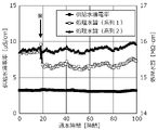
運転開始から18時間が経過した時点で、系列1のEDI装置の前段には粒状活性炭を充填した充填カラムを設置し、系列2のEDI装置の前段には繊維状活性炭を充填した充填カラムを設置し、各EDI装置における処理水質と運転電圧の変化とを調べた。粒状活性炭としてはフタムラ化学株式会社製の粒状活性炭CWを使用し、繊維状活性炭としてはオルガノ株式会社製の繊維状活性炭フィルターFAC-2を使用した。各活性炭に対する通水量は、空間速度SVで500h-1とした。結果を図7及び図8に示す。図7において、処理水質は処理水の抵抗率で示している。また図7には、供給水の導電率の計測結果も示している。図8は、運転開始時の運転電圧を1とする相対値によって運転電圧の変化を示している。図7及び図8において「※」印を付した矢印は、その時点で充填カラムを挿入したことを示している。 When 18 hours have passed from the start of operation, a packed column filled with granular activated carbon is installed in front of the EDI device of series 1, and a packed column filled with fibrous activated carbon is installed in front of the EDI device of series 2. Then, the changes in treated water quality and operating voltage in each EDI device were investigated. As the granular activated carbon, the granular activated carbon CW manufactured by Futamura Chemical Co., Ltd. was used, and as the fibrous activated carbon, the fibrous activated carbon filter FAC-2 manufactured by Organo Corporation was used. The amount of water flowing through each activated carbon was set to 500 h -1 at the space velocity SV. The results are shown in FIGS. 7 and 8. In FIG. 7, the treated water quality is shown by the resistivity of the treated water. FIG. 7 also shows the measurement results of the conductivity of the supplied water. FIG. 8 shows a change in the operating voltage according to a relative value with the operating voltage at the start of operation as 1. The arrows marked with “*” in FIGS. 7 and 8 indicate that the filling column was inserted at that time.
酸化剤を除去する充填材として粒状活性炭を採用した系列1では、充填カラムの設置後、即座に処理水質が低下したが、繊維状活性炭を使用した系列2に関してはそのような傾向は確認されなかった。また、運転電圧に関し、粒状活性炭を使用する系列1の方が、繊維状活性炭を使用する系列2に比べ、徐々に電圧が低下することが分かる。 In Series 1 where granular activated carbon was used as the filler for removing the oxidant, the quality of the treated water deteriorated immediately after the filling column was installed, but such a tendency was not confirmed for Series 2 using fibrous activated carbon. rice field. Further, regarding the operating voltage, it can be seen that the voltage of the series 1 using the granular activated carbon gradually decreases as compared with the series 2 using the fibrous activated carbon.
[実施例2]
粒状活性炭と繊維状活性炭について、高流速で通水したときの遊離塩素除去性能を比較した。粒状活性炭及び繊維状活性炭をそれぞれカラムに充填し、空間速度SVを1000h-1として相模原市の水道水を通水し、通水開始から所定の時間が経過した時点においてカラムの入口と出口での遊離塩素濃度を測定し、カラムにおいてどれだけの遊離塩素が除去されたかを求めて遊離塩素除去率を算出した。実験時において、使用した水道水の遊離塩素濃度は0.6~0.7mg/Lであった。また粒状活性炭及び繊維状活性炭としては、実施例1で使用したものと同一規格のものを使用した。結果を表1に示す。
[Example 2]
We compared the free chlorine removal performance of granular activated carbon and fibrous activated carbon when water was passed at a high flow velocity. The column is filled with granular activated charcoal and fibrous activated charcoal, respectively, and tap water of Sagamihara City is passed through at a space velocity SV of 1000 h -1 , and when a predetermined time has passed from the start of water passing, the column inlet and outlet. The free chlorine concentration was measured, and the free chlorine removal rate was calculated by determining how much free chlorine was removed in the column. At the time of the experiment, the free chlorine concentration of the tap water used was 0.6 to 0.7 mg / L. As the granular activated carbon and the fibrous activated carbon, those having the same specifications as those used in Example 1 were used. The results are shown in Table 1.

表1より、繊維状活性炭の方が粒状活性炭よりも遊離塩素の除去率が高かった。また、経時による遊離塩素除去率の低下は、繊維状活性炭の方が小さかった。 From Table 1, the fibrous activated carbon had a higher removal rate of free chlorine than the granular activated carbon. In addition, the decrease in the free chlorine removal rate with time was smaller in the fibrous activated carbon.
[実施例3]
遊離塩素を含む被処理水が与えられたときの保護装置の有無によるEDI装置の損傷の程度の違いを調べた。図9に示すように、2段逆浸透膜透過水に次亜塩素酸ナトリウム水溶液を添加して遊離塩素濃度が0.05mg/L程度の模擬水を生成し、この模擬水を同一構成の2台のEDI装置に並列に通水する構成とした。このとき、一方のEDI装置の前段には、繊維状活性炭を充填した保護装置を設け、繊維状活性炭を通過した模擬水がEDI装置に供給されるようにした。繊維状活性炭における通水の空間速度SVを1540h-1とした。そして各EDI装置において、通水量を一定として通水差圧を測定した。保護装置として、オルガノ株式会社製の繊維状活性炭フィルターFAC-2を使用した。
[Example 3]
The difference in the degree of damage to the EDI device depending on the presence or absence of a protective device when water to be treated containing free chlorine was given was investigated. As shown in FIG. 9, a sodium hypochlorite aqueous solution is added to the two-stage reverse osmosis membrane permeated water to generate simulated water having a free chlorine concentration of about 0.05 mg / L, and the simulated water has the same configuration as 2 The configuration was such that water was passed in parallel to the EDI device. At this time, a protective device filled with fibrous activated carbon was provided in front of one of the EDI devices so that simulated water that had passed through the fibrous activated carbon was supplied to the EDI device. The space velocity SV of water flow in the fibrous activated carbon was set to 1540 h -1 . Then, in each EDI device, the water flow differential pressure was measured with the water flow amount constant. As a protective device, a fibrous activated carbon filter FAC-2 manufactured by Organo Corporation was used.
その結果、運転開始から200時間を経過した時点で、保護装置を設けていない方のEDI装置における通水差圧が、前段に保護装置を設けたEDI装置の通水差圧よりも約1.4倍高くなった。 As a result, when 200 hours have passed from the start of operation, the water flow differential pressure in the EDI device without the protective device is about 1. It's four times higher.
さらに運転開始から700時間が経過した時点で運転を停止し、保護装置を設けていない方のEDI装置を解体し、内部の状況を確認したところ、第1小脱塩室76(図5参照)への被処理水流入部においてイオン交換樹脂が膨潤し、流路を閉塞している状態が確認できた。これは、低濃度とはいえ酸化剤が流入するとともに電流が通電していたことで強い酸化作用が働き、イオン交換樹脂が酸化劣化を引き起こしたためと考えられる。一般的に、イオン交換樹脂が酸化劣化を引き起こすと、イオン交換樹脂の樹脂マトリクスの架橋構造が損傷を受け、膨潤することが知られている。 Furthermore, when 700 hours had passed from the start of operation, the operation was stopped, the EDI device without the protective device was disassembled, and the internal condition was checked. As a result, the first small desalination chamber 76 (see FIG. 5). It was confirmed that the ion exchange resin swelled in the inflow portion of the water to be treated and blocked the flow path. It is considered that this is because the ion exchange resin caused oxidative deterioration due to the strong oxidative action due to the inflow of the oxidant and the energization of the electric current even though the concentration was low. It is generally known that when an ion exchange resin causes oxidative deterioration, the crosslinked structure of the resin matrix of the ion exchange resin is damaged and swells.
10 電気式脱イオン水製造装置(EDI装置)
15 ポンプ
20 逆浸透装置
30 保護装置
31 充填材カートリッジ(繊維状活性炭)
32 充填材カートリッジ(粒状活性炭)
33 ろ過膜
35 膜脱気装置
10 Electric deionized water production equipment (EDI equipment)
15
32 Filler cartridge (granular activated carbon)
33
Claims (9)
前記逆浸透膜を透過した透過水が供給されて前記透過水中の酸化剤を除去する保護装置を有し、
前記保護装置は、前記透過水が供給される充填材として繊維状活性炭を備え、
前記保護装置を通過した透過水が前記電気式脱イオン水製造装置に供給されることを特徴とする、水処理システム。 In a water treatment system including a reverse osmosis membrane and an electric deionized water production device
It has a protective device to which the permeated water that has permeated the reverse osmosis membrane is supplied and removes the oxidizing agent in the permeated water.
The protective device includes fibrous activated carbon as a filler to which the permeated water is supplied.
A water treatment system characterized in that permeated water that has passed through the protective device is supplied to the electric deionized water production device.
水中の酸化剤を除去する充填材として繊維状活性炭を有する保護装置に、前記逆浸透膜を透過した透過水を通水し、
前記保護装置を通過した透過水を前記電気式脱イオン水製造装置に供給する、水処理システムの運転方法。 It is an operation method of a water treatment system equipped with a reverse osmosis membrane and an electric deionized water production device.
Permeate water that has permeated the reverse osmosis membrane is passed through a protective device that has fibrous activated carbon as a filler that removes the oxidant in the water.
A method for operating a water treatment system in which permeated water that has passed through the protective device is supplied to the electric deionized water production device.
供給される水中の酸化剤を除去する充填材と、
前記充填材を格納するカートリッジ式の容器とを有し、
前記充填材は繊維状活性炭であり、
前記充填材に通水するときの空間速度が500h-1以上2000h-1以下であり、前記充填剤を通過した水を前記電気式脱イオン水製造装置に供給するように構成されている保護装置。 It is a protective device that is detachably provided in the rear stage of the reverse osmosis membrane and in the front stage of the electric deionized water production device so that the permeated water from the reverse osmosis membrane flows in .
A filler that removes the oxidizer in the supplied water,
It has a cartridge type container for storing the filler and has.
The filler is fibrous activated carbon and is
A protective device having a space velocity of 500 h -1 or more and 2000 h -1 or less when water is passed through the filler, and is configured to supply water that has passed through the filler to the electric deionized water producing apparatus. ..
Priority Applications (1)
| Application Number | Priority Date | Filing Date | Title |
|---|---|---|---|
| JP2018144181A JP7065723B2 (en) | 2018-07-31 | 2018-07-31 | Water treatment system, its operation method, and protection device |
Applications Claiming Priority (1)
| Application Number | Priority Date | Filing Date | Title |
|---|---|---|---|
| JP2018144181A JP7065723B2 (en) | 2018-07-31 | 2018-07-31 | Water treatment system, its operation method, and protection device |
Publications (2)
| Publication Number | Publication Date |
|---|---|
| JP2020018970A JP2020018970A (en) | 2020-02-06 |
| JP7065723B2 true JP7065723B2 (en) | 2022-05-12 |
Family
ID=69587809
Family Applications (1)
| Application Number | Title | Priority Date | Filing Date |
|---|---|---|---|
| JP2018144181A Active JP7065723B2 (en) | 2018-07-31 | 2018-07-31 | Water treatment system, its operation method, and protection device |
Country Status (1)
| Country | Link |
|---|---|
| JP (1) | JP7065723B2 (en) |
Families Citing this family (3)
| Publication number | Priority date | Publication date | Assignee | Title |
|---|---|---|---|---|
| US20230149857A1 (en) * | 2020-05-06 | 2023-05-18 | Evoqua Water Technologies Llc | Improved chlorine tolerance of continuous electrodeionization modules |
| JP7731691B2 (en) * | 2021-04-20 | 2025-09-01 | オルガノ株式会社 | Water treatment method and water treatment device |
| JP7605694B2 (en) * | 2021-05-27 | 2024-12-24 | オルガノ株式会社 | Water treatment method and water treatment device |
Citations (8)
| Publication number | Priority date | Publication date | Assignee | Title |
|---|---|---|---|---|
| JP2001129543A (en) | 1999-11-05 | 2001-05-15 | Nippon Rensui Co Ltd | Pure water production equipment |
| JP2003245659A (en) | 2002-02-25 | 2003-09-02 | Nomura Micro Sci Co Ltd | Wastewater treatment method and apparatus |
| US20050263457A1 (en) | 2004-05-27 | 2005-12-01 | Wilkins Frederick C | Water treatment system and process |
| JP2006212518A (en) | 2005-02-02 | 2006-08-17 | Kurita Water Ind Ltd | Pure water production equipment |
| JP2011088104A (en) | 2009-10-26 | 2011-05-06 | Japan Organo Co Ltd | System and method for treating water |
| JP2012210593A (en) | 2011-03-31 | 2012-11-01 | Kurita Water Ind Ltd | Ultrapure water producing system and ultrapure water producing method |
| JP2013000725A (en) | 2011-06-21 | 2013-01-07 | Nomura Micro Sci Co Ltd | Method of operating water purification system, and the water purification system |
| JP2018122274A (en) | 2017-02-03 | 2018-08-09 | オルガノ株式会社 | Water treatment system, operation method thereof and protection device |
-
2018
- 2018-07-31 JP JP2018144181A patent/JP7065723B2/en active Active
Patent Citations (9)
| Publication number | Priority date | Publication date | Assignee | Title |
|---|---|---|---|---|
| JP2001129543A (en) | 1999-11-05 | 2001-05-15 | Nippon Rensui Co Ltd | Pure water production equipment |
| JP2003245659A (en) | 2002-02-25 | 2003-09-02 | Nomura Micro Sci Co Ltd | Wastewater treatment method and apparatus |
| US20050263457A1 (en) | 2004-05-27 | 2005-12-01 | Wilkins Frederick C | Water treatment system and process |
| JP2008500170A (en) | 2004-05-27 | 2008-01-10 | シ−メンス ウォーター テクノロジーズ ホールディング コープ | Water treatment system and process |
| JP2006212518A (en) | 2005-02-02 | 2006-08-17 | Kurita Water Ind Ltd | Pure water production equipment |
| JP2011088104A (en) | 2009-10-26 | 2011-05-06 | Japan Organo Co Ltd | System and method for treating water |
| JP2012210593A (en) | 2011-03-31 | 2012-11-01 | Kurita Water Ind Ltd | Ultrapure water producing system and ultrapure water producing method |
| JP2013000725A (en) | 2011-06-21 | 2013-01-07 | Nomura Micro Sci Co Ltd | Method of operating water purification system, and the water purification system |
| JP2018122274A (en) | 2017-02-03 | 2018-08-09 | オルガノ株式会社 | Water treatment system, operation method thereof and protection device |
Also Published As
| Publication number | Publication date |
|---|---|
| JP2020018970A (en) | 2020-02-06 |
Similar Documents
| Publication | Publication Date | Title |
|---|---|---|
| JP3826690B2 (en) | Electrodeionization device and pure water production device | |
| JP5733351B2 (en) | Method and apparatus for treating boron-containing water | |
| JP5617231B2 (en) | Method and apparatus for purifying ion exchange resin | |
| JP2008518758A (en) | Concentration recycle loop with filtration module | |
| JP2002512883A (en) | Apparatus and method for removing strong oxidants from liquids | |
| TW201726557A (en) | Ultrapure water production apparatus and method for operating thereof that can efficiently remove boron and rapidly prevent leakage thereof | |
| JP7065723B2 (en) | Water treatment system, its operation method, and protection device | |
| WO2013109789A1 (en) | Water purification system | |
| JP7246399B2 (en) | Pure water production system and pure water production method | |
| WO2022190608A1 (en) | Method and apparatus for treating water | |
| JP5193984B2 (en) | Water treatment system and water treatment method | |
| JP6228471B2 (en) | To-be-treated water processing apparatus, pure water production apparatus and to-be-treated water processing method | |
| WO2021235107A1 (en) | Boron removal device and boron removal method, and pure water production device and pure water production method | |
| JP5729062B2 (en) | Water treatment method and water treatment system | |
| CN102510837A (en) | Water processing device | |
| JP6916625B2 (en) | Water treatment system and its operation method and protective device | |
| JP2018001072A (en) | Cleaning method of electric demineralizer | |
| JP2012196634A (en) | Method and system for treatment of water | |
| JP5285135B2 (en) | Water treatment system and water treatment method | |
| JP2010036173A (en) | Water treatment system and water treatment method | |
| JP2001276821A (en) | Method of preventing clogging of reverse osmosis membrane device and reverse osmosis membrane device | |
| JP5640825B2 (en) | Water treatment method and water treatment system | |
| CN115697916A (en) | Improved Chlorine Tolerance for Continuous Electrodeionization Modules | |
| JP6561448B2 (en) | Method and apparatus for electrodeionization treatment of vanadium-containing water | |
| CN116322947B (en) | Ultrapure water production system and ultrapure water production method |
Legal Events
| Date | Code | Title | Description |
|---|---|---|---|
| A621 | Written request for application examination |
Free format text: JAPANESE INTERMEDIATE CODE: A621 Effective date: 20210305 |
|
| A977 | Report on retrieval |
Free format text: JAPANESE INTERMEDIATE CODE: A971007 Effective date: 20211104 |
|
| A131 | Notification of reasons for refusal |
Free format text: JAPANESE INTERMEDIATE CODE: A131 Effective date: 20211116 |
|
| A521 | Request for written amendment filed |
Free format text: JAPANESE INTERMEDIATE CODE: A523 Effective date: 20211215 |
|
| TRDD | Decision of grant or rejection written | ||
| A01 | Written decision to grant a patent or to grant a registration (utility model) |
Free format text: JAPANESE INTERMEDIATE CODE: A01 Effective date: 20220419 |
|
| A61 | First payment of annual fees (during grant procedure) |
Free format text: JAPANESE INTERMEDIATE CODE: A61 Effective date: 20220426 |
|
| R150 | Certificate of patent or registration of utility model |
Ref document number: 7065723 Country of ref document: JP Free format text: JAPANESE INTERMEDIATE CODE: R150 |
|
| R250 | Receipt of annual fees |
Free format text: JAPANESE INTERMEDIATE CODE: R250 |
|
| R250 | Receipt of annual fees |
Free format text: JAPANESE INTERMEDIATE CODE: R250 |