JP7069909B2 - 液体吐出ヘッドおよび液体吐出装置 - Google Patents
液体吐出ヘッドおよび液体吐出装置 Download PDFInfo
- Publication number
- JP7069909B2 JP7069909B2 JP2018053278A JP2018053278A JP7069909B2 JP 7069909 B2 JP7069909 B2 JP 7069909B2 JP 2018053278 A JP2018053278 A JP 2018053278A JP 2018053278 A JP2018053278 A JP 2018053278A JP 7069909 B2 JP7069909 B2 JP 7069909B2
- Authority
- JP
- Japan
- Prior art keywords
- flow path
- circulation
- circulation flow
- connection terminal
- liquid discharge
- Prior art date
- Legal status (The legal status is an assumption and is not a legal conclusion. Google has not performed a legal analysis and makes no representation as to the accuracy of the status listed.)
- Active
Links
- 239000007788 liquid Substances 0.000 title claims description 171
- 230000004308 accommodation Effects 0.000 claims description 18
- 238000012546 transfer Methods 0.000 claims description 15
- 239000000126 substance Substances 0.000 claims description 9
- 230000008859 change Effects 0.000 claims description 6
- 238000007599 discharging Methods 0.000 claims description 2
- 238000004891 communication Methods 0.000 description 135
- 239000000976 ink Substances 0.000 description 105
- 239000000758 substrate Substances 0.000 description 73
- 239000010410 layer Substances 0.000 description 52
- 230000001681 protective effect Effects 0.000 description 29
- 239000011347 resin Substances 0.000 description 23
- 229920005989 resin Polymers 0.000 description 23
- 230000007246 mechanism Effects 0.000 description 21
- 239000000463 material Substances 0.000 description 19
- 238000004519 manufacturing process Methods 0.000 description 13
- 239000012790 adhesive layer Substances 0.000 description 10
- 238000001816 cooling Methods 0.000 description 9
- 238000000034 method Methods 0.000 description 9
- 239000000853 adhesive Substances 0.000 description 7
- 230000001070 adhesive effect Effects 0.000 description 7
- 238000012545 processing Methods 0.000 description 7
- 229910004298 SiO 2 Inorganic materials 0.000 description 6
- 238000005304 joining Methods 0.000 description 6
- 239000004065 semiconductor Substances 0.000 description 6
- XUIMIQQOPSSXEZ-UHFFFAOYSA-N Silicon Chemical compound [Si] XUIMIQQOPSSXEZ-UHFFFAOYSA-N 0.000 description 5
- 238000009434 installation Methods 0.000 description 5
- 239000002184 metal Substances 0.000 description 5
- 238000003825 pressing Methods 0.000 description 5
- 238000007639 printing Methods 0.000 description 5
- 229910052710 silicon Inorganic materials 0.000 description 5
- 239000010703 silicon Substances 0.000 description 5
- 238000010586 diagram Methods 0.000 description 4
- 230000000149 penetrating effect Effects 0.000 description 4
- 238000004040 coloring Methods 0.000 description 3
- 239000013078 crystal Substances 0.000 description 3
- 239000012530 fluid Substances 0.000 description 3
- 238000010438 heat treatment Methods 0.000 description 3
- 239000003921 oil Substances 0.000 description 3
- 239000000243 solution Substances 0.000 description 3
- 239000006096 absorbing agent Substances 0.000 description 2
- 239000004020 conductor Substances 0.000 description 2
- 238000001312 dry etching Methods 0.000 description 2
- 230000000694 effects Effects 0.000 description 2
- 238000005401 electroluminescence Methods 0.000 description 2
- 230000020169 heat generation Effects 0.000 description 2
- 238000010030 laminating Methods 0.000 description 2
- 230000004048 modification Effects 0.000 description 2
- 238000012986 modification Methods 0.000 description 2
- 238000005192 partition Methods 0.000 description 2
- 239000000049 pigment Substances 0.000 description 2
- 238000000638 solvent extraction Methods 0.000 description 2
- 230000008719 thickening Effects 0.000 description 2
- 230000032258 transport Effects 0.000 description 2
- 230000007723 transport mechanism Effects 0.000 description 2
- 238000001039 wet etching Methods 0.000 description 2
- 239000012298 atmosphere Substances 0.000 description 1
- 230000015572 biosynthetic process Effects 0.000 description 1
- 239000003795 chemical substances by application Substances 0.000 description 1
- 239000004744 fabric Substances 0.000 description 1
- 238000001746 injection moulding Methods 0.000 description 1
- 238000007641 inkjet printing Methods 0.000 description 1
- 239000004973 liquid crystal related substance Substances 0.000 description 1
- 230000008569 process Effects 0.000 description 1
- 238000011084 recovery Methods 0.000 description 1
- 230000003252 repetitive effect Effects 0.000 description 1
- 238000007789 sealing Methods 0.000 description 1
- 238000009751 slip forming Methods 0.000 description 1
- 229910001220 stainless steel Inorganic materials 0.000 description 1
- 239000010935 stainless steel Substances 0.000 description 1
- 238000003860 storage Methods 0.000 description 1
Images


Classifications
-
- B—PERFORMING OPERATIONS; TRANSPORTING
- B41—PRINTING; LINING MACHINES; TYPEWRITERS; STAMPS
- B41J—TYPEWRITERS; SELECTIVE PRINTING MECHANISMS, i.e. MECHANISMS PRINTING OTHERWISE THAN FROM A FORME; CORRECTION OF TYPOGRAPHICAL ERRORS
- B41J2/00—Typewriters or selective printing mechanisms characterised by the printing or marking process for which they are designed
- B41J2/005—Typewriters or selective printing mechanisms characterised by the printing or marking process for which they are designed characterised by bringing liquid or particles selectively into contact with a printing material
- B41J2/01—Ink jet
- B41J2/135—Nozzles
- B41J2/14—Structure thereof only for on-demand ink jet heads
- B41J2/14201—Structure of print heads with piezoelectric elements
- B41J2/14233—Structure of print heads with piezoelectric elements of film type, deformed by bending and disposed on a diaphragm
-
- B—PERFORMING OPERATIONS; TRANSPORTING
- B41—PRINTING; LINING MACHINES; TYPEWRITERS; STAMPS
- B41J—TYPEWRITERS; SELECTIVE PRINTING MECHANISMS, i.e. MECHANISMS PRINTING OTHERWISE THAN FROM A FORME; CORRECTION OF TYPOGRAPHICAL ERRORS
- B41J2/00—Typewriters or selective printing mechanisms characterised by the printing or marking process for which they are designed
- B41J2/005—Typewriters or selective printing mechanisms characterised by the printing or marking process for which they are designed characterised by bringing liquid or particles selectively into contact with a printing material
- B41J2/01—Ink jet
- B41J2/135—Nozzles
- B41J2/14—Structure thereof only for on-demand ink jet heads
- B41J2/14201—Structure of print heads with piezoelectric elements
-
- B—PERFORMING OPERATIONS; TRANSPORTING
- B41—PRINTING; LINING MACHINES; TYPEWRITERS; STAMPS
- B41J—TYPEWRITERS; SELECTIVE PRINTING MECHANISMS, i.e. MECHANISMS PRINTING OTHERWISE THAN FROM A FORME; CORRECTION OF TYPOGRAPHICAL ERRORS
- B41J2/00—Typewriters or selective printing mechanisms characterised by the printing or marking process for which they are designed
- B41J2/005—Typewriters or selective printing mechanisms characterised by the printing or marking process for which they are designed characterised by bringing liquid or particles selectively into contact with a printing material
- B41J2/01—Ink jet
- B41J2/135—Nozzles
- B41J2/14—Structure thereof only for on-demand ink jet heads
- B41J2002/14362—Assembling elements of heads
-
- B—PERFORMING OPERATIONS; TRANSPORTING
- B41—PRINTING; LINING MACHINES; TYPEWRITERS; STAMPS
- B41J—TYPEWRITERS; SELECTIVE PRINTING MECHANISMS, i.e. MECHANISMS PRINTING OTHERWISE THAN FROM A FORME; CORRECTION OF TYPOGRAPHICAL ERRORS
- B41J2/00—Typewriters or selective printing mechanisms characterised by the printing or marking process for which they are designed
- B41J2/005—Typewriters or selective printing mechanisms characterised by the printing or marking process for which they are designed characterised by bringing liquid or particles selectively into contact with a printing material
- B41J2/01—Ink jet
- B41J2/135—Nozzles
- B41J2/14—Structure thereof only for on-demand ink jet heads
- B41J2002/14411—Groove in the nozzle plate
-
- B—PERFORMING OPERATIONS; TRANSPORTING
- B41—PRINTING; LINING MACHINES; TYPEWRITERS; STAMPS
- B41J—TYPEWRITERS; SELECTIVE PRINTING MECHANISMS, i.e. MECHANISMS PRINTING OTHERWISE THAN FROM A FORME; CORRECTION OF TYPOGRAPHICAL ERRORS
- B41J2/00—Typewriters or selective printing mechanisms characterised by the printing or marking process for which they are designed
- B41J2/005—Typewriters or selective printing mechanisms characterised by the printing or marking process for which they are designed characterised by bringing liquid or particles selectively into contact with a printing material
- B41J2/01—Ink jet
- B41J2/135—Nozzles
- B41J2/14—Structure thereof only for on-demand ink jet heads
- B41J2002/14419—Manifold
-
- B—PERFORMING OPERATIONS; TRANSPORTING
- B41—PRINTING; LINING MACHINES; TYPEWRITERS; STAMPS
- B41J—TYPEWRITERS; SELECTIVE PRINTING MECHANISMS, i.e. MECHANISMS PRINTING OTHERWISE THAN FROM A FORME; CORRECTION OF TYPOGRAPHICAL ERRORS
- B41J2/00—Typewriters or selective printing mechanisms characterised by the printing or marking process for which they are designed
- B41J2/005—Typewriters or selective printing mechanisms characterised by the printing or marking process for which they are designed characterised by bringing liquid or particles selectively into contact with a printing material
- B41J2/01—Ink jet
- B41J2/135—Nozzles
- B41J2/14—Structure thereof only for on-demand ink jet heads
- B41J2002/14491—Electrical connection
-
- B—PERFORMING OPERATIONS; TRANSPORTING
- B41—PRINTING; LINING MACHINES; TYPEWRITERS; STAMPS
- B41J—TYPEWRITERS; SELECTIVE PRINTING MECHANISMS, i.e. MECHANISMS PRINTING OTHERWISE THAN FROM A FORME; CORRECTION OF TYPOGRAPHICAL ERRORS
- B41J2202/00—Embodiments of or processes related to ink-jet or thermal heads
- B41J2202/01—Embodiments of or processes related to ink-jet heads
- B41J2202/11—Embodiments of or processes related to ink-jet heads characterised by specific geometrical characteristics
-
- B—PERFORMING OPERATIONS; TRANSPORTING
- B41—PRINTING; LINING MACHINES; TYPEWRITERS; STAMPS
- B41J—TYPEWRITERS; SELECTIVE PRINTING MECHANISMS, i.e. MECHANISMS PRINTING OTHERWISE THAN FROM A FORME; CORRECTION OF TYPOGRAPHICAL ERRORS
- B41J2202/00—Embodiments of or processes related to ink-jet or thermal heads
- B41J2202/01—Embodiments of or processes related to ink-jet heads
- B41J2202/12—Embodiments of or processes related to ink-jet heads with ink circulating through the whole print head
Landscapes
- Particle Formation And Scattering Control In Inkjet Printers (AREA)
- Ink Jet (AREA)
Description
図1は、本発明の第1実施形態に係る液体吐出装置100の部分的な構成図である。第1実施形態の液体吐出装置100は、液体の例示であるインクを印刷用紙等の媒体12に吐出するインクジェット方式の印刷装置である。媒体12は、典型的には印刷用紙であるが、樹脂フィルムまたは布帛等の任意の材質の印刷対象を媒体12とすることもできる。図1に示す液体吐出装置100は、制御ユニット20と搬送機構22と移動機構24と液体吐出ヘッド26とを具備する。液体吐出装置100にはインクを貯留する液体容器14が装着される。
図2は、液体吐出ヘッド26の分解斜視図であり、図3は、液体吐出ヘッド26をY方向に垂直なIII-III断面で切断した場合の断面図である。図4は、圧電素子44の断面図である。図2および図3に示すように、本実施形態の液体吐出ヘッド26は、第1ノズル列L1の各ノズルN(第1ノズルの例示)に関連する要素と第2ノズル列L2の各ノズルN(第2ノズルの例示)に関連する要素とが仮想面Oを挟んで面対称に配置された構造である。すなわち、液体吐出ヘッド26のうち仮想面Oを挟んでX方向の正側の部分(以下「第1部分」という)P1とX方向の負側の部分(以下「第2部分」という)P2とで構造は実質的に共通する。第1ノズル列L1の複数のノズルNは第1部分P1に形成され、第2ノズル列L2の複数のノズルNは第2部分P2に形成される。仮想面Oは、第1部分P1と第2部分P2との境界面に相当する。
次に、本実施形態の循環経路の構成について説明する。図5は、循環経路に着目した液体吐出ヘッド26の構成図である。図5に示すように、循環液室Sは、第1ノズル列L1および第2ノズル列L2に沿って複数のノズルNにわたり連続する。具体的には、第1ノズル列L1のノズルNと第2ノズル列L2のノズルNとの間に循環液室Sが形成される。したがって、図2および図3に示すように、循環液室Sは、第1部分P1の連通路63と第2部分P2の連通路63との間に位置する。このように、第1実施形態の第1流路部材30は、第1部分P1における圧力室C(第1圧力室)および連通路63(第1連通路)と、第2部分P2における圧力室C(第2圧力室)および連通路63(第2連通路)と、第1部分P1の連通路63と第2部分P2の連通路63との間に位置する循環液室Sとが形成された構造体である。本実施形態の第1流路部材30は、循環液室Sと各連通路63との間を仕切る壁状の部分である隔壁部69を含む。
図3に示す配線基板45は、第1流路部材30に積層される保護基板46および駆動IC47によって構成される。本実施形態の配線基板45は、保護基板46に駆動IC47を設置し、駆動IC47と圧電素子44との間の配線を保護基板46に設ける場合を例示する。保護基板46は、複数の圧電素子44を保護するための板状部材である。本実施形態の保護基板46は、振動部42の表面Fcに設置される。なお、保護基板46は、圧力室基板34の表面に設置されるようにしてもよい。第2流路部材48のうちZ方向の正側の表面にはY方向に延在する溝状の凹部484が形成され、圧力室基板34と振動部42と配線基板45とはその凹部484の内側に収容される。平面視で凹部484が第1領域Aに重なるように第1流路部材30と第2流路部材48とが積層されることで、凹部484のZ方向の負側の開口は第1流路部材30で閉じられる。凹部484は大気開放されていてもよい。こうして本実施形態の凹部484は、配線基板45を収容するための収容空間Gとして機能する。このように、収容空間Gは、第1流路部材30と第2流路部材48との間に、平面視で第1領域Aに重なるように形成される。
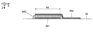
ここで、圧電素子44を駆動するための液体吐出ヘッド26の配線構造について説明する。図7および図8は、本実施形態の圧電素子44を駆動するための配線構造についての説明図である。図7は、振動部42および圧電素子44をZ方向(上方)から見た平面図である。図8は、保護基板46をZ方向(上方)から見た平面図である。本実施形態では、第1圧電素子と第2圧電素子を備える。図7において仮想面Oから見てX方向の一方側(例えば第1部分P1側)に配列される複数の圧電素子44が第1圧電素子に相当し、仮想面Oから見てX方向の他方側(例えば第2部分P2側)に配列される複数の圧電素子44が第2圧電素子に相当する。
本発明の第2実施形態について説明する。以下に例示する各形態において作用や機能が第1実施形態と同様である要素については、第1実施形態の説明で使用した符号を流用して各々の詳細な説明を適宜に省略する。図10は、第2実施形態に係る液体吐出ヘッド26の構成を示す断面図であり、図3に対応する。図11および図12は、第2実施形態の圧電素子44を駆動するための配線構造についての説明図である。図11は、振動部42および圧電素子44をZ方向(上方)から見た平面図であり、図7に対応する。図12は、保護基板46をZ方向(上方)から見た平面図であり、図8に対応する。
本発明の第3実施形態について説明する。第1実施形態および第2実施形態では、保護基板46と駆動IC47を別体にして積層することで配線基板45を構成する場合を例示した。第3実施形態では、保護基板46と駆動IC47とを一体で配線基板45を構成する場合を例示する。
以上に例示した態様および実施形態は多様に変形され得る。具体的な変形の態様を以下に例示する。以下の例示や上述の態様から任意に選択された2以上の態様は、相互に矛盾しない範囲で適宜に併合され得る。
Claims (11)
- 液体を吐出するノズルに連通する圧力室が形成される第1流路部材と、
第1方向に互いに重なるように前記第1流路部材に積層される第2流路部材と、
前記圧力室に圧力変化を発生させる駆動素子に電気的に接続される接続端子が配置される配線基板と、
前記圧力室に液体を流入する第1循環流路と、
前記圧力室から液体を流出する第2循環流路と、を具備し、
前記第1流路部材の表面は、前記配線基板を介して前記第2流路部材に積層される第1領域と、前記配線基板を介さずに前記第2流路部材に積層される第2領域とを含み、
前記第2流路部材の表面は、前記第1領域と前記第2領域とに重なるように前記第1流路部材の表面に接合され、
前記第1循環流路と前記第2循環流路のそれぞれは、前記第2領域において前記第1流路部材に形成される流路と前記第2流路部材に形成される流路とが連通して形成され、
前記第1方向からみたときに前記第2循環流路と前記配線基板が重なる幅は、前記第1方向からみたときに前記第1循環流路と前記配線基板が重なる幅よりも大きい
液体吐出ヘッド。 - 前記第1方向に交差する第2方向において、前記第1循環流路と前記第2循環流路との間に前記配線基板が配置される
請求項1に記載の液体吐出ヘッド。 - 前記圧力室は、前記第1方向および前記第2方向に交差する第3方向に複数配置され、
前記第3方向において、前記第1循環流路と前記第2循環流路とが前記複数の圧力室にわたって連続し、
前記第2方向において、前記第1循環流路と前記第2循環流路との間に前記複数の圧力室のそれぞれが配置される
請求項2に記載の液体吐出ヘッド。 - 前記第1循環流路および前記第2循環流路はそれぞれ、前記第1方向に延びる第1流路と、前記第2方向に延びる第2流路とを備え、
前記第1循環流路の第2流路または前記第2循環流路の第2流路は、前記第1方向から見て前記接続端子に重なる
請求項3に記載の液体吐出ヘッド。 - 前記駆動素子は、前記圧力室のそれぞれに対応して配置され、
前記接続端子は、前記駆動素子のそれぞれに共通の電位が印加される第1接続端子と、前記駆動素子のそれぞれに個別の電位が印加される第2接続端子と、を含み、
前記第2方向において、前記第1接続端子よりも前記第2接続端子の方が、前記第1循環流路よりも前記第2循環流路に近い位置にある
請求項2または請求項3に記載の液体吐出ヘッド。 - 前記第2循環流路は、前記第1方向に延びる第1流路と、前記第2方向に延びる第2流路とを備え、
前記第2流路は、前記第1方向から見て前記第2接続端子に重なる
請求項5に記載の液体吐出ヘッド。 - 前記第1流路部材と前記第2流路部材との間には、平面視で前記第1領域に重なるように収容空間が形成され、
前記配線基板は、前記収容空間に設置され、
前記収容空間内において前記配線基板と前記第2循環流路側の壁面との間には、伝熱物質が介在する
請求項5または請求項6に記載の液体吐出ヘッド。 - 前記第1流路部材には、前記圧力室のぞれぞれと前記第1循環流路を接続する第1個別流路と、前記圧力室のぞれぞれと前記第2循環流路を接続する第2個別流路とが形成され、
前記第1方向から見て、前記第1接続端子は前記第1循環流路よりも前記第1個別流路に近く、
前記第1方向から見て、前記第2接続端子は前記第2循環流路よりも前記第2個別流路に近い
請求項5から請求項7の何れかに記載の液体吐出ヘッド。 - 前記第1接続端子には、前記第1方向から見て前記第1流路部材のうち前記第1個別流路間の領域に重なる前記第1接続端子が含まれ、
前記第2接続端子には、前記第1方向から見て前記第1流路部材のうち前記第2個別流路間の領域に重なる前記第2接続端子が含まれる
請求項8に記載の液体吐出ヘッド。 - 前記第2流路部材には、前記循環流路のうち、前記圧力室へ液体を供給するための流路と、前記圧力室から液体を流出するための流路とが設けられる
請求項1から請求項9の何れかに記載の液体吐出ヘッド。 - 請求項1から請求項10の何れかに記載の液体吐出ヘッドを備える
液体吐出装置。
Priority Applications (2)
| Application Number | Priority Date | Filing Date | Title |
|---|---|---|---|
| JP2018053278A JP7069909B2 (ja) | 2018-03-20 | 2018-03-20 | 液体吐出ヘッドおよび液体吐出装置 |
| US16/358,548 US10894408B2 (en) | 2018-03-20 | 2019-03-19 | Liquid discharging head and liquid discharging apparatus |
Applications Claiming Priority (1)
| Application Number | Priority Date | Filing Date | Title |
|---|---|---|---|
| JP2018053278A JP7069909B2 (ja) | 2018-03-20 | 2018-03-20 | 液体吐出ヘッドおよび液体吐出装置 |
Publications (2)
| Publication Number | Publication Date |
|---|---|
| JP2019162833A JP2019162833A (ja) | 2019-09-26 |
| JP7069909B2 true JP7069909B2 (ja) | 2022-05-18 |
Family
ID=67983422
Family Applications (1)
| Application Number | Title | Priority Date | Filing Date |
|---|---|---|---|
| JP2018053278A Active JP7069909B2 (ja) | 2018-03-20 | 2018-03-20 | 液体吐出ヘッドおよび液体吐出装置 |
Country Status (2)
| Country | Link |
|---|---|
| US (1) | US10894408B2 (ja) |
| JP (1) | JP7069909B2 (ja) |
Families Citing this family (11)
| Publication number | Priority date | Publication date | Assignee | Title |
|---|---|---|---|---|
| JP7322563B2 (ja) * | 2019-07-17 | 2023-08-08 | セイコーエプソン株式会社 | 液体噴射ヘッド及びその製造方法並びに液体噴射システム |
| JP7404812B2 (ja) * | 2019-11-26 | 2023-12-26 | ブラザー工業株式会社 | 液体噴射ヘッド |
| JP7404811B2 (ja) * | 2019-11-26 | 2023-12-26 | ブラザー工業株式会社 | 液体噴射ヘッド |
| JP7434854B2 (ja) * | 2019-12-03 | 2024-02-21 | セイコーエプソン株式会社 | 液体噴射ヘッドおよび液体噴射システム |
| JP7439482B2 (ja) * | 2019-12-03 | 2024-02-28 | セイコーエプソン株式会社 | 液体噴射ヘッドおよび液体噴射システム |
| JP7392534B2 (ja) * | 2020-03-18 | 2023-12-06 | 株式会社リコー | 液体吐出ヘッド、液体吐出ユニット及び液体を吐出する装置 |
| JP7512721B2 (ja) * | 2020-07-07 | 2024-07-09 | コニカミノルタ株式会社 | インクジェットヘッドの製造方法、インクジェットヘッド及びインクジェット記録装置 |
| US12391052B2 (en) | 2023-02-16 | 2025-08-19 | Ricoh Company, Ltd. | Passive mixer in jetting channels of a printhead |
| US12291032B2 (en) * | 2023-02-16 | 2025-05-06 | Ricoh Company, Ltd. | Flow-through printhead |
| US12533882B2 (en) | 2023-02-16 | 2026-01-27 | Ricoh Company, Ltd. | Fluid mixers in jetting channels of a printhead |
| US12358301B2 (en) | 2023-02-16 | 2025-07-15 | Ricoh Company Ltd. | Active mixer in jetting channels of a printhead |
Citations (11)
| Publication number | Priority date | Publication date | Assignee | Title |
|---|---|---|---|---|
| JP2012061704A (ja) | 2010-09-15 | 2012-03-29 | Ricoh Co Ltd | 液滴吐出ヘッド、ヘッドカートリッジ、画像形成装置、及びマイクロポンプ |
| JP2012061717A (ja) | 2010-09-16 | 2012-03-29 | Ricoh Co Ltd | 液滴吐出ヘッド及びインクジェット記録装置 |
| US20120167823A1 (en) | 2010-12-29 | 2012-07-05 | Gardner Deane A | Electrode configurations for piezoelectric actuators |
| JP2015134507A (ja) | 2015-05-08 | 2015-07-27 | セイコーエプソン株式会社 | 液体噴射ヘッド及び液体噴射装置 |
| JP2016049675A (ja) | 2014-08-29 | 2016-04-11 | キヤノン株式会社 | 液体吐出ヘッドとその製造方法 |
| JP2016147429A (ja) | 2015-02-12 | 2016-08-18 | 株式会社東芝 | インクジェットヘッド |
| JP2016159514A (ja) | 2015-03-02 | 2016-09-05 | 富士フイルム株式会社 | 液体吐出装置、及び液体吐出ヘッドの異物排出方法 |
| JP2017056664A (ja) | 2015-09-18 | 2017-03-23 | コニカミノルタ株式会社 | インクジェットヘッド、インクジェット記録装置及びインクジェットヘッドの製造方法 |
| US20170225457A1 (en) | 2016-02-10 | 2017-08-10 | Seiko Epson Corporation | Liquid ejecting head and liquid ejecting apparatus |
| JP2017140821A (ja) | 2016-02-10 | 2017-08-17 | セイコーエプソン株式会社 | 液体噴射ヘッドおよび液体噴射装置 |
| JP2017196786A (ja) | 2016-04-27 | 2017-11-02 | セイコーエプソン株式会社 | Memsデバイス、液体噴射ヘッド、及び、液体噴射装置 |
Family Cites Families (9)
| Publication number | Priority date | Publication date | Assignee | Title |
|---|---|---|---|---|
| JP2007118309A (ja) * | 2005-10-26 | 2007-05-17 | Fujifilm Corp | インクジェット記録ヘッド及びこれを備えた画像形成装置 |
| JP2008149594A (ja) | 2006-12-19 | 2008-07-03 | Toshiba Tec Corp | インクジェット記録装置 |
| JP4855992B2 (ja) | 2007-03-30 | 2012-01-18 | 富士フイルム株式会社 | 液体循環装置、画像形成装置、及び液体循環方法 |
| JP2011131533A (ja) | 2009-12-25 | 2011-07-07 | Sii Printek Inc | 液体噴射ヘッド及び液体噴射装置 |
| JP5364084B2 (ja) | 2010-03-16 | 2013-12-11 | パナソニック株式会社 | インクジェット装置 |
| JP5750753B2 (ja) | 2011-01-11 | 2015-07-22 | セイコーエプソン株式会社 | 液体噴射ヘッド及び液体噴射装置 |
| JP5764601B2 (ja) | 2013-03-27 | 2015-08-19 | 富士フイルム株式会社 | 液体吐出ヘッド及び液体吐出装置 |
| JP2015066864A (ja) | 2013-09-30 | 2015-04-13 | 京セラ株式会社 | 液体吐出ヘッドおよびそれを用いた記録装置 |
| JP5863910B1 (ja) | 2014-08-29 | 2016-02-17 | キヤノン株式会社 | 素子基板の製造方法 |
-
2018
- 2018-03-20 JP JP2018053278A patent/JP7069909B2/ja active Active
-
2019
- 2019-03-19 US US16/358,548 patent/US10894408B2/en active Active
Patent Citations (11)
| Publication number | Priority date | Publication date | Assignee | Title |
|---|---|---|---|---|
| JP2012061704A (ja) | 2010-09-15 | 2012-03-29 | Ricoh Co Ltd | 液滴吐出ヘッド、ヘッドカートリッジ、画像形成装置、及びマイクロポンプ |
| JP2012061717A (ja) | 2010-09-16 | 2012-03-29 | Ricoh Co Ltd | 液滴吐出ヘッド及びインクジェット記録装置 |
| US20120167823A1 (en) | 2010-12-29 | 2012-07-05 | Gardner Deane A | Electrode configurations for piezoelectric actuators |
| JP2016049675A (ja) | 2014-08-29 | 2016-04-11 | キヤノン株式会社 | 液体吐出ヘッドとその製造方法 |
| JP2016147429A (ja) | 2015-02-12 | 2016-08-18 | 株式会社東芝 | インクジェットヘッド |
| JP2016159514A (ja) | 2015-03-02 | 2016-09-05 | 富士フイルム株式会社 | 液体吐出装置、及び液体吐出ヘッドの異物排出方法 |
| JP2015134507A (ja) | 2015-05-08 | 2015-07-27 | セイコーエプソン株式会社 | 液体噴射ヘッド及び液体噴射装置 |
| JP2017056664A (ja) | 2015-09-18 | 2017-03-23 | コニカミノルタ株式会社 | インクジェットヘッド、インクジェット記録装置及びインクジェットヘッドの製造方法 |
| US20170225457A1 (en) | 2016-02-10 | 2017-08-10 | Seiko Epson Corporation | Liquid ejecting head and liquid ejecting apparatus |
| JP2017140821A (ja) | 2016-02-10 | 2017-08-17 | セイコーエプソン株式会社 | 液体噴射ヘッドおよび液体噴射装置 |
| JP2017196786A (ja) | 2016-04-27 | 2017-11-02 | セイコーエプソン株式会社 | Memsデバイス、液体噴射ヘッド、及び、液体噴射装置 |
Also Published As
| Publication number | Publication date |
|---|---|
| JP2019162833A (ja) | 2019-09-26 |
| US10894408B2 (en) | 2021-01-19 |
| US20190291429A1 (en) | 2019-09-26 |
Similar Documents
| Publication | Publication Date | Title |
|---|---|---|
| JP7069909B2 (ja) | 液体吐出ヘッドおよび液体吐出装置 | |
| JP6969139B2 (ja) | 液体噴射ヘッドおよび液体噴射装置 | |
| JP7230980B2 (ja) | 液体吐出ヘッドおよび液体吐出装置 | |
| EP3213922B1 (en) | Liquid ejecting head and liquid ejecting apparatus | |
| US10507648B2 (en) | Liquid ejecting head and liquid ejecting apparatus | |
| CN110654116B (zh) | 液体喷出头、液体喷出装置以及液体喷出头的制造方法 | |
| US10513115B2 (en) | Liquid ejecting head and liquid ejecting apparatus | |
| JP2017140821A (ja) | 液体噴射ヘッドおよび液体噴射装置 | |
| JP7102777B2 (ja) | 液体吐出ヘッドおよび液体吐出装置 | |
| JP6992595B2 (ja) | 液体吐出ヘッドおよび液体吐出装置 | |
| JP2020001306A (ja) | 液体吐出ヘッドおよび液体吐出装置 | |
| JP2018039174A (ja) | 圧力発生デバイスの製造方法 | |
| WO2018116833A1 (ja) | 液体噴射ヘッドおよび液体噴射装置 | |
| JP7047398B2 (ja) | 液体吐出ヘッドおよび液体吐出装置 | |
| US10449765B2 (en) | Liquid ejecting head and liquid ejecting apparatus |
Legal Events
| Date | Code | Title | Description |
|---|---|---|---|
| A621 | Written request for application examination |
Free format text: JAPANESE INTERMEDIATE CODE: A621 Effective date: 20210204 |
|
| A977 | Report on retrieval |
Free format text: JAPANESE INTERMEDIATE CODE: A971007 Effective date: 20211215 |
|
| A131 | Notification of reasons for refusal |
Free format text: JAPANESE INTERMEDIATE CODE: A131 Effective date: 20220104 |
|
| A521 | Request for written amendment filed |
Free format text: JAPANESE INTERMEDIATE CODE: A523 Effective date: 20220304 |
|
| TRDD | Decision of grant or rejection written | ||
| A01 | Written decision to grant a patent or to grant a registration (utility model) |
Free format text: JAPANESE INTERMEDIATE CODE: A01 Effective date: 20220405 |
|
| A61 | First payment of annual fees (during grant procedure) |
Free format text: JAPANESE INTERMEDIATE CODE: A61 Effective date: 20220418 |
|
| R150 | Certificate of patent or registration of utility model |
Ref document number: 7069909 Country of ref document: JP Free format text: JAPANESE INTERMEDIATE CODE: R150 |